Article

Acceleration-Aware Path Planning with Waypoints

Institute of Computer Graphics, Johannes Kepler University Linz, 4040 Linz, Austria
*
Author to whom correspondence should be addressed.
Drones 2021, 5(4), 143; https://doi.org/10.3390/drones5040143
Submission received: 29 October 2021 / Revised: 23 November 2021 / Accepted: 26 November 2021 / Published: 27 November 2021
(This article belongs to the Special Issue Feature Papers of Drones)

Abstract

:
In this article we demonstrate that acceleration and deceleration of direction-turning drones at waypoints have a significant influence to path planning which is important to be considered for time-critical applications, such as drone-supported search and rescue. We present a new path planning approach that takes acceleration and deceleration into account. It follows a local gradient ascend strategy which locally minimizes turns while maximizing search probability accumulation. Our approach outperforms classic coverage-based path planning algorithms, such as spiral- and grid-search, as well as potential field methods that consider search probability distributions. We apply this method in the context of autonomous search and rescue drones and in combination with a novel synthetic aperture imaging technique, called Airborne Optical Sectioning (AOS), which removes occlusion of vegetation and forest in real-time.

1. Introduction

Autonomous UAVs are becoming more and more adept at handling complex tasks and are thus used in various civil and commercial applications [1]. However, autonomous and adaptive path planning still poses serious challenges due to numerous constraints, such as limited energy, speed, and payload. An additional constraint in search and rescue scenarios can be considered of locating the target as fast as possible. This type of problem is well studied in literature and is termed as a minimum time search problem (MTS) [2,3,4,5,6,7,8,9,10,11,12,13,14]. The most prominent objective in these approaches is to optimize the expected time of target detection [3,4,5,6]; however, other alternative approaches involve optimizing the probability of target detection [7,8,9,15], minimizing its counterpart, i.e., probability of non-detection [10,11] or maximizing the information gain [12,13,16]. Various sub-optimal and heuristics-based algorithms such as gradient-based approaches [7,10,11,12,15], cross-entropy optimization [2,5], Bayesian optimization algorithms [4], ant colony optimization [6], or genetic algorithms [3] have been proposed to address the NP-hard complex problem [13]. These approaches can also be differentiated based on the considered UAV dynamics models, where they either do not consider velocity at all [2,4,5,6,7,8,9,15], or only consider simple linear velocity models [3,10,11] but not acceleration or deceleration.
In addition to efficient path planning, effective imaging is also essential for wilderness search and rescue operations. Large depth of field of conventional cameras (resultant of having a narrow aperture) often project sharply the entire occlusion volumes (such as forests) into the images captured. Objects of interest (people in search and rescue scenario) at a particular distance often remain occluded by the occluders (such as forests). Airborne optical sectioning (AOS) is a wide synthetic-aperture aerial imaging technique that applies camera drones for the real-time removal of occlusion caused by vegetation, such as forests [15,17,18,19,20,21,22,23,24,25]. It has been demonstrated as a capable and effective tool in various applications (such as archaeology [17], wildlife observation [21], and search and rescue [15,24]). AOS’ efficiency concerning the occlusion density, occluder sizes, number of integrated samples, and size of the synthetic aperture has been explained by employing a randomly distributed statistical model [19,25]. By computationally integrating individual images captured over a large scan area (possibly hundreds to thousands of square meters) with narrow aperture camera optics, AOS generates integral images of an extremely shallow depth of field below an occluding volume (cf. Figure 1b). These images enable optical slicing through dense occlusion (caused by leaves, branches, and bushes) and reveal focused targets in each slice (such as artefacts, objects, wildlife, or persons) which would remain occluded for regular cameras (cf. Figure 1c). A fully autonomous and classification-driven UAV (cf. Figure 1a) has been developed and deployed for carrying out wilderness search and rescue operations [15]. The system presented in [15] comprises of two essential and independent modules (AOS based imaging and classification module and an adaptive path planning module). Thermal images are acquired in a 1D sampling pattern and integrated for achieving an occlusion free view of the ground/target. A pre-trained deep learning network achieves an average precision of 86% for detecting person in integral images. In [24] we have already demonstrated how classification of partially occluded persons in forests using aerial thermal images is significantly more effective when AOS is used to integrate single images before classification rather than combined classification results of single images. However, certain environmental conditions (warm background temperature, precipitation, fog, etc.) can affect the performance of the thermal imaging system and thus limiting the efficiency of AOS.
In our previous work [15], a potential-field [14] based adaptive path planning was applied that was driven by confidences from a deep-learning person classifier collected during the flight. The probability map used by the path-planning algorithm was continuously updated with classification confidence values of potential findings. However, acceleration and deceleration were also not considered, which makes path-planning highly unrealistic in practice—especially for rotor-based drone systems that navigate through waypoints. In this work, we focus on achieving a linear velocity over the scanned region while considering the UAV’s acceleration and deceleration to plan its trajectories. Achieving constant velocity over the scanned region is essential for uniform sampling in AOS [15]. We also propose a gradient-based approach that maximizes the probability of target detection with the above mentioned limitations. This proposed path planning algorithm can directly replace our old potential-field based method while utilizing the other aspects of AOS (e.g., integral imaging, person classification) for target detection as it is described in [15]. Our trajectory planning, which takes a dynamic UAV model with acceleration and deceleration into account, is described in Section 2.1 whereas Section 2.2 describes our proposed algorithm to maximize the probability of target detection. Section 3 presents simulation results for various representative probability distributions, and in Section 4 we discuss limitations of our approach and the potential of future UAV models and flight controllers with more dynamic maneuver capabilities for path planning.

2. Materials and Methods

Most commercial drones (especially rotor-based drones) only support piecewise linear waypoint flights and are still not able to fly continuously at a high uniform speed. They need to stop, or slow down (due to limitations of maneuvering and tracking speed capability), before changing directions. Not considering the changes in acceleration and deceleration leads to an unrealistic path planning, as illustrated in Section 2.1. In Section 2.2, we present a new path planning approach that considers acceleration/deceleration and outperforms our previous potential field based method used in [15], as well as classic coverage-based path planning algorithms (i.e., spiral search or grid search).

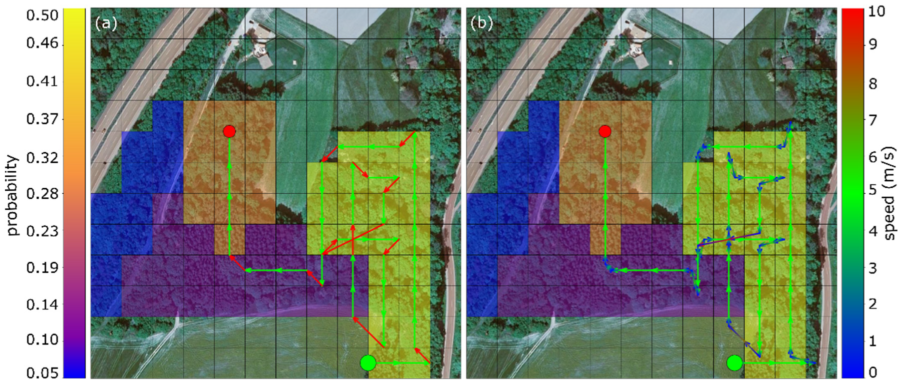
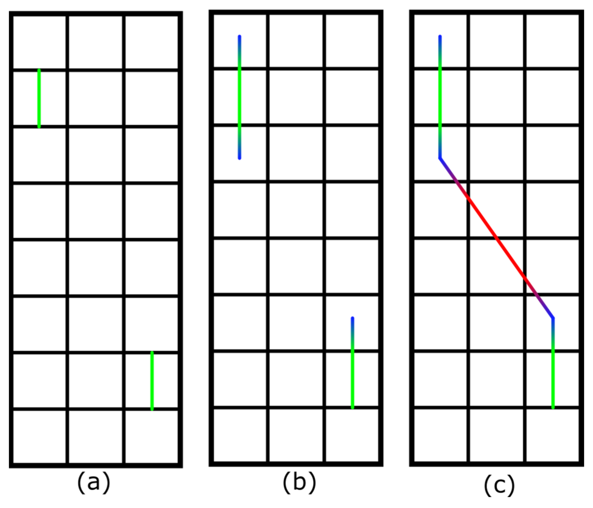
2.1. Acceleration-Driven Trajectory Planning

As in [15], we want to assume the search region to be discretized into a uniform grid of 30 m × 30 m cells, and that cells are sampled horizontally, vertically, or diagonally at constant velocity to ensure full coverage of the cell within the drones’ field-of-view and uniform sampling. Similar to our work in [15], we utilize calibrated cameras and GPS information to project the digital elevation model of the terrain within each cell. The drone samples multiple single images while crossing each cell and combines them to AOS integral images. Flight speed within a cell must be constant to ensure uniform sampling for AOS, since the person classifier used (YOLOv4-tiny network architecture [26]) was trained with uniformly sampled image data. A non-uniform sampling which differs from the training data would significantly reduce classification rate. Person classification is carried out for each integral image. Each cell is associated with the probability of a person being found within it (cf. Figure 2). The probability maps are initially defined by the rescue team (a uniform probability map is assumed in its absence), and is adapted during flight based on confidence scores of the person classifier. The quality of the initial probability map accounts for how much area has to be scanned until the person is potentially found. In the worst case, the whole area has to be covered. A discussion on adaptive sampling and person classification is out of the scope of this article, and is independent of the presented path-planning approach. The interested reader is referred to [15] for more details. Thus far, constant flight speeds were assumed for the entire path through search area, which does not hold in practice because of finitely fast accelerations and decelerations at the turning waypoints.
Our new trajectory planner ensures that each scanned cell is crossed exactly with the desired and constant scanning speed (see Figure 3a). This, however, introduces additional linear trajectories (for acceleration and deceleration shown in Figure 3b) at both ends (entrance and exit) of the scanned cell. Before entering it, the drone must be decelerated to the desired scan speed and after leaving it the drone can be accelerated again to the drone’s maximum velocity (to progress quicker to the next scan cell, see Figure 3c). We utilize a kinematics based linear motion model to generate these piecewise linear path segments. The distance between the entrance and exit edges of the scanned cell and the auxiliary waypoints at which deceleration starts and acceleration is finished are computed as follows: d = ( v 2 2 v 1 2 ) / ( 2 a ) , where v 1 , v 2 are the velocities before and after acceleration/deceleration, and a the rate of acceleration/deceleration (positive/negative).
Note, that if neighboring cells are scanned in the same flight direction, the drone is not accelerated or decelerated, but continues at constant scan speed. Thus, the auxiliary deceleration and acceleration trajectories are only needed to bridge distances between non-neighboring cells fast, or if flight direction must be changed. They are flown at the maximum speed that the drone supports without overshooting into the scan cell too fast.
Figure 2 illustrates, for the same probability map as used in [15], the difference in potential-field-based adaptive path-planning when acceleration/deceleration is ignored (Figure 2a), as it was the case in [15], and when it is considered (Figure 2b). With our drone prototype (a 4.5 kg MikroKopter OktoXL 6S12, measured average acceleration/deceleration of 1.4 m/s2, a scan speed of 5 m/s, and a maximum flight speed of 10 m/s) and for a 6.3 ha search area, a flight path of 1291 m and a total of 225 s flight time was determined until the target person is found for constant flying speed (i.e., ignoring acceleration/deceleration). In practice, however, this does not hold because the acceleration/deceleration trajectories are ignored. Considering them as explained above results in a 1489 m long flight path and in a flight time of 380 s instead (an increase in required flight time by a factor of 1.7).
We conclude that for waypoint-based path-planning acceleration driven trajectory planning leads to more realistic results and in more accurate estimates of drones’ limited energy and flight time. However, it should be noted that the drones´ energy consumption does not only depend on flight time and acceleration/deceleration but also on many other varying factors like wind, type of drone, gross weight, etc. Our trajectory computes an ideal path without considering these unpredictable outside forces like wind, etc. The flight controllers available on commercial rotor based drones are capable to correct any drifts that are caused by such forces.
When only minimizing flight time or flight distance while ignoring local detection probabilities but considering acceleration/deceleration, classic coverage-based path planning algorithms (i.e., spiral search or grid search) are fastest in traversing the entire search region fully. This is primarily due to a minimum number of direction changes caused by these search techniques, which also minimizes acceleration/deceleration trajectories (see also examples in Appendix A). However, classification probabilities cannot be ignored if the overall goal is to find a person as fast and as reliable as possible. Therefore, we utilize the integral (area) under the sequentially accumulated probability ( p ( t ) ) curve w.r.t time (APT) for evaluating the efficiency of different path planning algorithms in Section 3. The upper limit of the integral is set by the path traversal time of the fastest algorithm (tmin).
APT = t m i n p ( t ) d t .
The following section presents a new path-planning approach that considers acceleration/deceleration, and that outperforms not only our previous potential-field based method, but also spiral search and grid search for AOS-supported search and rescue applications.

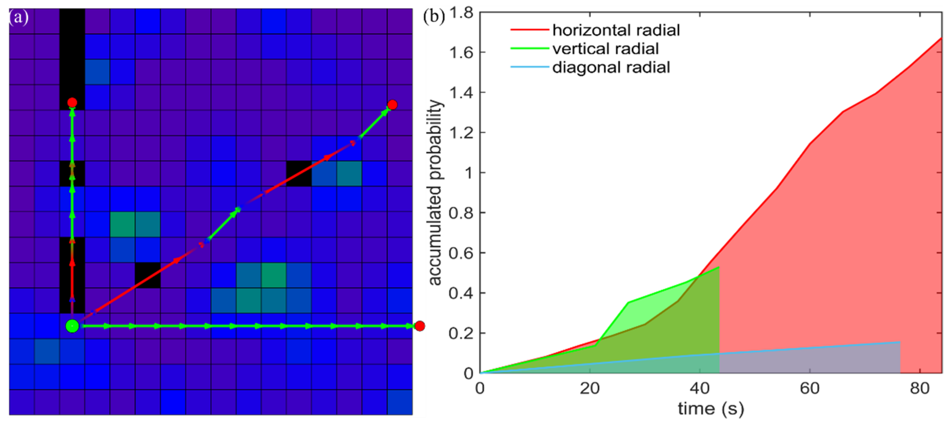
2.2. Radial Gradient Accent (RGA)

Observing the need to minimize turns while utilizing an acceleration driven trajectory planner, we propose a new gradient-based method to maximize the probability of target detection while minimizing flight time by reducing turns (cf. Figure 4).
To decide for the next cell to be scanned from the drone’s current position, a unique set of directions (called radials) is determined in such a way that each radial will have a unique direction and that all radials (originating all from the current cell’s center) together will cross the centers of all unvisited cells. Each unvisited cell is then assigned to its corresponding radial if its center is crossed by it. How many radials exist depends on the resolution of the grid and the number of remaining unvisited cells. For each radial (i.e., the cells assigned to it), we now compute the required trajectories and resulting flight time, as explained in Section 2.1, and select the radial with the highest gradient of accumulated probability w.r.t time (APT). Note, that the APT is similar to the unnormalized cumulative distribution function and the area under this function is the inverse of the Expected Time (ET) of target detection as explained in [2]. The first unvisited cell along this radial is sampled next. Then we iteratively repeat the above process to decide for the next cells to be scanned until all cells are visited or the target is found (i.e., classification with high confidence confirmed by the rescue team, as in [15]).
Overall, this approach follows a local APT gradient ascend strategy with the assumption that after the last cell was scanned, the best local choice for the next scan direction is the one which contributes the highest APT gradient because it maximizes probability accumulation while reducing turns (and with that, flight time). Note that, as explained in Section 2.1, unvisited cell segments are scanned at constant scan speed, but are approached at maximum flight speed. This requires deceleration and acceleration before and after scanning.

3. Results

In this section, we evaluate our Radial Gradient Accent (RGA) method by comparing it against grid search and spiral search which, as fastest coverage-based path planning algorithms, set the speed bars for full grid coverage but do not consider probabilities; and the potential field algorithm in [15] (extended to acceleration/deceleration, as discussed in Section 2.1 and shown in Figure 2a). We apply the probability maps shown in Figure 5 as representative examples for various scenarios during search and rescue operations conducted in the field. Note, however, that the behavior of a lost person depends on many factors (including psychology, physiology, age, gender, etc.) and is not considered here while generating the representative probability maps. For evaluation, only simulations have been carried out to compare the different path planning algorithms under identical conditions. An exact comparison in the field would not be possible, since our online-path planning depends on classification scores which vary with many factors, such as local occlusion, lighting, and wind. Thus, carrying out two search flights under exactly identical conditions is not possible.
Figure 6 and Figure 7 illustrate the performance of the potential field algorithm and our Radial Gradient Accent approach without and with considering acceleration/deceleration on the scattered-smooth probability map (Figure 5b). Results for the other probability maps can be found in Appendix A. Appendix B shows the results of our algorithm for a uniform probability map (assumed in cases where the initial probability map is unreliable or unavailable). The resulting path is more or less uniform spiral like depending on the initial starting position.
Comparing the results in Figure 6 and Figure 7 reveals visually already that RGA requires much less turns (i.e., accelerations/decelerations) and samples more uniformly than the potential field algorithm. A quantitative comparison for all probability maps shown in Figure 5 is presented in Figure 8.
The APT plots in Figure 8 show that although spiral- and grid search always cover the full search region fastest (planned trajectories are presented in Appendix A), they do not maximize detection reliability over time. The latter corresponds to the integral of the accumulated probability w.r.t time plots up to the shortest possible full coverage time. Table 1 presents a quantitative summary.
From the results presented in Figure 8 and Table 1 it can be seen that our RGA approach always outperforms spiral- and grid-search, as well as potential field in all cases as its APT score (which is the accumulated probability w.r.t time integral) is significantly higher (28%, 50%, 11% respectively). Note, that APT combines accumulated detection probability over search time.

4. Discussion and Conclusions

This article demonstrates that considering acceleration and deceleration matters for realistic path planning—especially when drones are applied, where velocity is by far not linear over the flight path. Acceleration and deceleration for waypoint sampling has a significant share of total flight time. Taking this into account is important especially for time-critical applications, such as search and rescue. Furthermore, we presented a new path planning approach, Radial Gradient Accent (RGA), which considers acceleration/deceleration. It follows a local gradient ascend strategy that locally minimizes turns while maximizing probability accumulation. In case of the 16 × 16 search grid resolutions that were chosen for our evaluations, RGA requires about 2.36 ms on a laptop equipped with Intel(R) Core(TM) i5-8250U CPU @ 1.60GHz and 8GB of RAM. Considering all radials per iteration, however, might be computationally too intensive for higher resolution grids and lower-performance on-board processors. Furthermore, many of the radials intersect only one cell at its center. Achieving a better radial coverage by considering also cells in the vicinity of the radials might lead to performance improvements. RGA is a greedy choice approach that strongly depends on the quality of local decisions. More efficient heuristics than the max. APT gradient might achieve better overall results (i.e., higher APT scores). Our algorithm could also be adapted and applied to drone swarms for conducting faster search and rescue operations. Additional constraints, such as collision and obstacle avoidance also needs to be considered. All of this has to be explored in the future. Currently, we require uniform sampling in AOS as we apply a uniformly distributed occlusion model to represent forest [19]. However, considering more complex, non-uniform occlusion model (e.g., if sparse and densely occluded regions can be measured during flight) will benefit from non-uniform sampling. This will be investigated in future.
The problem of acceleration and deceleration is caused mainly because today’s flight controllers used in commercial drones follow waypoints in a piecewise linear fashion. Sharper turns at waypoints require major acceleration and deceleration—especially for rotor-based drones. The influence of acceleration and deceleration can be significantly reduced if future flight controllers (especially in combination with agile wing-based drones and fast tracking) allow polynomial instead of piece-wise linear flight paths. Figure 9 illustrates this effect for the assumption that the drone is physically able to fly continuously at constant velocity (without acceleration/deceleration). Instead of flying from waypoint to waypoint, we simulate continuous heading changes (at differential time steps of 1 s) towards the highest probability gradient (at +/−20 deg limits for smooth heading changes at realistic velocities). As shown in Figure 9 for the scattered-smooth probability map, a constant-velocity-based path-planning (continuous gradient) clearly outperforms (in APT integral and sampling uniformity) an acceleration-aware path-planning, such as RGA, that is applied for classical waypoint navigation which requires acceleration and deceleration. Thus, improvements in aerodynamics and flight-control open entirely new doors for efficient UAV-supported search and rescue missions.

Author Contributions

Conceptualization, O.B. and R.O.; methodology, R.O.; software, R.O.; validation, R.O., O.B., and I.K.; formal analysis, R.O.; investigation, R.O.; resources, R.O.; data curation, R.O.; writing—original draft preparation, R.O., O.B., and I.K.; writing—review and editing, R.O., O.B., and I.K.; visualization, R.O.; supervision, O.B.; project administration, O.B.; funding acquisition, O.B. All authors have read and agreed to the published version of the manuscript.

Funding

This research was funded by the Austrian Science Fund (FWF) under grant number P 32185-NBL, and by the State of Upper Austria and the Austrian Federal Ministry of Education, Sci-ence and Research via the LIT–Linz Institute of Technology under grant number LIT-2019-8-SEE-114.

Institutional Review Board Statement

Not applicable.

Informed Consent Statement

Not applicable.

Data Availability Statement

The data and code for acceleration-aware waypoint based path planning approach along with the proposed trajectory planner is available on GitHub: https://github.com/JKU-ICG/AOS/ last accessed on 27 November 2021.

Conflicts of Interest

The authors declare no conflict of interest.

Appendix A

Planned trajectories with (a) and without (b) acceleration/deceleration and overage maps (c) for all probability maps and methods (Table 1). Examples are shown in Figure 6 and Figure 7. Drones 05 00143 i0a1 Drones 05 00143 i0a2 Drones 05 00143 i0a3 Drones 05 00143 i0a4 Drones 05 00143 i0a5 Drones 05 00143 i0a6

Appendix B

Planned trajectories with (a) and without (b) acceleration/deceleration and coverage maps (c) for a uniform probability map and methods (Table 1). Drones 05 00143 i0a7

References

  1. Shakhatreh, H.; Sawalmeh, A.H.; Al-Fuqaha, A.; Dou, Z.; Almaita, E.; Khalil, I.; Othman, N.S.; Khreishah, A.; Guizani, M. Unmanned Aerial Vehicles (UAVs): A Survey on Civil Applications and Key Research Challenges. IEEE Access 2019, 7, 48572–48634. [Google Scholar] [CrossRef]
  2. Lanillos, P.; Besada-Portas, E.; Pajares, G.; Ruz, J.J. Minimum time search for lost targets using cross entropy optimization. In Proceedings of the 2012 IEEE/RSJ International Conference on Intelligent Robots and Systems, Vilamoura, Portugal, 7–12 October 2012; pp. 602–609. [Google Scholar] [CrossRef]
  3. Pérez-Carabaza, S.; Besada-Portas, E.; Lopez-Orozco, J.A.; Pajares, G. Minimum Time Search in Real-World Scenarios Using Multiple UAVs with Onboard Orientable Cameras. J. Sens. 2019, 2019, 7673859. [Google Scholar] [CrossRef]
  4. Lanillos, P.; Yañez-Zuluaga, J.; Ruz, J.J.; Besada-Portas, E. A Bayesian approach for constrained multi-agent minimum time search in uncertain dynamic domains. In Proceedings of the 2013 15th Genetic and Evolutionary Computation Conference, GECCO 2013, Amsterdam, The Netherlands, 6–10 July 2013; pp. 391–398. [Google Scholar]
  5. Lanillos, P.; Besada-Portas, E.; Lopez-Orozco, J.A.; De la Cruz, J.M. Minimum Time Search in Uncertain Dynamic Domains with Complex Sensorial Platforms. Sensors 2014, 14, 14131–14179. [Google Scholar] [CrossRef] [PubMed] [Green Version]
  6. Perez-Carabaza, S.; Bermudez-Ortega, J.; Besada-Portas, E.; Lopez-Orozco, J.A.; De La Cruz, J.M. A Multi-UAV minimum time search planner based on ACOR. In Proceedings of the 2017 Genetic and Evolutionary Computation Conference, GECCO 2017, Berlin, Germany, 15–19 July 2017; pp. 35–42. [Google Scholar]
  7. Tisdale, J.; Kim, Z.W.; Hedrick, J.K. Autonomous UAV path planning and estimation: An online path planning framework for cooperative search and localization. IEEE Robot. Autom. Mag. 2009, 16, 35–42. [Google Scholar] [CrossRef]
  8. Wong, E.M.; Bourgault, F.; Furukawa, T. Multi-vehicle Bayesian search for multiple lost targets. In Proceedings of the 2005 IEEE International Conference on Robotics and Automation, Barcelona, Spain, 18–22 April 2005; pp. 3169–3174. [Google Scholar]
  9. Bourgault, F.; Furukawa, T.; Durrant-Whyte, H. Optimal search for a lost target in a bayesian world in Field and Service Robotics. In Proceedings of the Recent Advances in Research and Applications, Lake Yamanaka, Japan, 14–16 July 2003; pp. 209–222. [Google Scholar]
  10. Gan, S.K.; Sukkarieh, S. Multi-UAV target search using explicit decentralized gradient-based negotiation. In Proceedings of the IEEE International Conference on Robotics and Automation, Shanghai, China, 9–13 May 2011; pp. 751–756. [Google Scholar]
  11. Lanillos, P.; Gan, S.K.; Besada-Portas, E.; Pajares, G.; Sukkarieh, S. Multi-UAV target search using decentralized gradient-based negotiation with expected observation. Inf. Sci. 2014, 282, 92–110. [Google Scholar] [CrossRef]
  12. Hu, J.; Xie, L.; Xu, J.; Xu, Z. Multi-agent cooperative target search. Sensors 2014, 14, 9408–9428. [Google Scholar] [CrossRef] [Green Version]
  13. Trummel, K.E.; Weisinger, J.R. The complexity of the optimal searcher path problem. Oper. Res. 1986, 34, 324–327. [Google Scholar] [CrossRef] [Green Version]
  14. Juan, V.S.; Santos, M.; Andújar, J.M. Intelligent UAV map generation and discrete path planning for search and rescue operations. Complexity 2018, 2018, 6879419. [Google Scholar] [CrossRef] [Green Version]
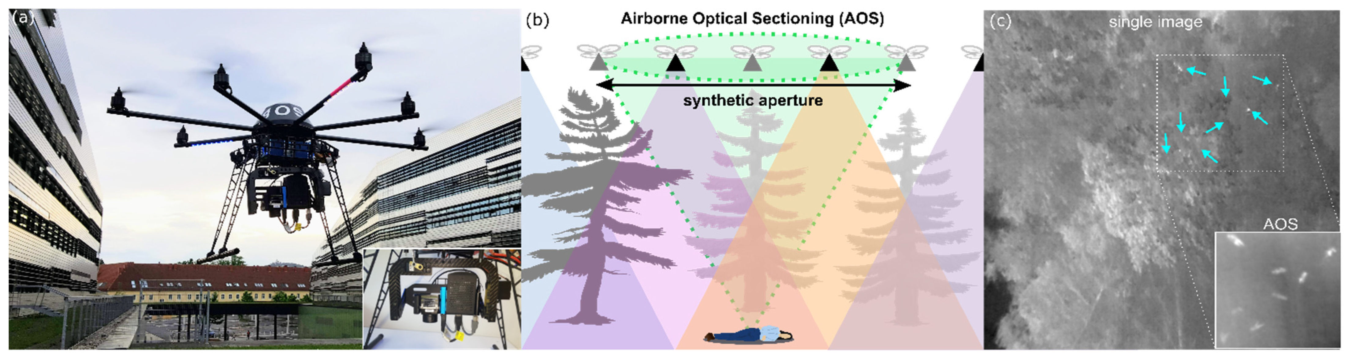
  15. Schedl, D.C.; Kurmi, I.; Bimber, O. An autonomous drone for search and rescue in forests using airborne optical sectioning. Sci. Robot. 2021, 6, eabg1188. [Google Scholar] [CrossRef] [PubMed]
  16. Meera, A.A.; Popović, M.; Millane, A.; Siegwart, R. Obstacle-aware Adaptive Informative Path Planning for UAV-based Target Search. In Proceedings of the 2019 International Conference on Robotics and Automation (ICRA), Montreal, QC, Canada, 20–24 May 2019; pp. 718–724. [Google Scholar] [CrossRef] [Green Version]
  17. Kurmi, I.; Schedl, D.C.; Bimber, O. Airborne optical sectioning. J. Imaging 2018, 4, 102. [Google Scholar] [CrossRef] [Green Version]
  18. Bimber, O.; Kurmi, I.; Schedl, D.C. Synthetic aperture imaging with drones. IEEE Comput. Graph. Appl. 2019, 39, 8–15. [Google Scholar] [CrossRef] [PubMed]
  19. Kurmi, I.; Schedl, D.C.; Bimber, O. A statistical view on synthetic aperture imaging for occlusion removal. IEEE Sensors J. 2019, 19, 9374–9383. [Google Scholar] [CrossRef] [Green Version]
  20. Kurmi, I.; Schedl, D.C.; Bimber, O. Thermal airborne optical sectioning. Remote Sens. 2019, 11, 1668. [Google Scholar] [CrossRef] [Green Version]
  21. Schedl, D.C.; Kurmi, I.; Bimber, O. Airborne optical sectioning for nesting observation. Sci. Rep. 2020, 10, 7254. [Google Scholar] [CrossRef] [PubMed]
  22. Kurmi, I.; Schedl, D.C.; Bimber, O. Fast Automatic Visibility Optimization for Thermal Synthetic Aperture Visualization. IEEE Geosci. Remote Sens. Lett. 2021, 18, 836–840. [Google Scholar] [CrossRef]
  23. Kurmi, I.; Schedl, D.C.; Bimber, O. Pose Error Reduction for Focus Enhancement in Thermal Synthetic Aperture Visualization. IEEE Geosci. Remote. Sens. Lett. 2021. to be published. [Google Scholar] [CrossRef]
  24. Schedl, D.C.; Kurmi, I.; Bimber, O. Search and rescue with airborne optical sectioning. Nat. Mach. Intell. 2020, 2, 783–790. [Google Scholar] [CrossRef]
  25. Kurmi, I.; Schedl, D.C.; Bimber, O. Combined person classification with airborne optical sectioning. arXiv 2021, arXiv:2106.10077. [Google Scholar]
  26. Bochkovskiy, A.; Wang, C.Y.; Liao, H.Y.M. YOLOv4: Optimal Speed and Accuracy of Object Detection. 2020. Unpublished work. Available online: https://arxiv.org/abs/2004.10934 (accessed on 15 November 2021).
Figure 1. Airborne Optical Sectioning (AOS). (a) An autonomous drone [15] was developed and deployed for search and rescue with its payload (thermal camera, Raspberry Pi, Intel Neural Compute Stick, LTE hat) shown in the inset. (b) Wide synthetic aperture imaging principle with AOS for search and rescue purposes. Single images captured through a large scan are computationally integrated (registered to the ground surface and averaged) to remove occlusion [15,17,18,19,20,21,22,23,24,25]. (c) Occlusion removal result with AOS: thermal signature of occluded people in single images is quite similar to that of trees. With AOS, we achieve an unoccluded view (integral image) of the people in real-time. A pre-trained deep learning classifier automatically detects them with >90% average precision [15,24].
Drones 05 00143 g001
Figure 2. Probability map of a practical search and rescue scenario considered in [15]. The potential field algorithm is used for path planning, as explained in [15]. (a) Ignoring acceleration/deceleration leads to an unrealistically short flight path and time of 1291 m and 225 s. (b) Considering acceleration/deceleration increases path-length and flight-time to 1489 m and 380 s, respectively. Start point (green circle), person found (red circle), detection probabilities (colors of cells), drone speed (colors of path segments). The axillary acceleration/deceleration trajectories are the segments that gradually change colors in (b). Each cell is 30 m × 30 m. The search area covers 6.3 ha.
Drones 05 00143 g002
Figure 3. Trajectory planner ensuring constant velocity for scanning over the desired scan cell ((a), here top left cell is visited first followed by the bottom right cell). Additional acceleration/deceleration path segments generated on both sides of the scan cells (b). Direct line segment in-between scan cells are flown with maximum flight speed (c). Colors indicate velocity (blue to red = slow to fast).
Drones 05 00143 g003
Figure 4. Radial Gradient Accent: (a) Three sample radials for a probability map and (b) their corresponding APT plots. Cell colors in (a) indicate probabilities (as in Figure 2). Black cells are previously visited cells. Green dot and red dots indicate current cell and end points of radials. Colors of trajectories indicate flight speed (as in Figure 2): scan speed (green line segments), max. flight speed (red line segments), acceleration/deceleration (blue line segments). Only cells with the centers located on the corresponding radial are considered for scanning. In this example, the horizontal radial is chosen next as it has the highest APT gradient (b).
Drones 05 00143 g004
Figure 5. Representative probability maps resembling real-life search and rescue scenarios used for evaluation. (a) Multiple scattered locations where the target could be found (scattered). (b) Scattered, but with smooth probability transitions (scattered-smooth). (c) Exponentially (Gaussian) decreasing probabilities from a certain center location (exponential). (d) Multiple connected regions (multiple-patches). (e,f) large and small single connected region (large-patch and small-patch).
Drones 05 00143 g005
Figure 6. Potential Field. (a) Planned trajectory including scan legs without considering acceleration/deceleration. (b) Planned trajectory considering acceleration/deceleration. (c) Coverage map showing how many images of a certain region have been sampled. The starting point is indicated with the green dot.
Drones 05 00143 g006
Figure 7. Radial Gradient Accent. (a) Planned trajectory including scan legs without considering acceleration/deceleration. (b) Planned trajectory considering acceleration/deceleration. (c) Coverage map showing how many images of a certain region have been sampled. The starting point is indicated with the green dot.
Drones 05 00143 g007
Figure 8. Accumulated probability w.r.t time (APT) plots for different probability maps. (a) scattered, (b) scattered-smooth, (c) exponential, (d) multiple-patches, (e) large-patch, (f) small-patch. The filled areas indicate the integrals up to the shortest full coverage time.
Drones 05 00143 g008
Figure 9. Constant-velocity assumption. (a) Planned trajectory with constant velocity and smooth heading changes. (b) Coverage map showing how many images of a certain region have been sampled. (c) Accumulated probability w.r.t time (APT) plots for acceleration-driven path planning (RGA) and constant-velocity-based path-planning (continuous gradient). The starting point is indicated with the green dot.
Drones 05 00143 g009
Table 1. Quantitative comparison (total flight time and distance, APT score) between considered path planning methods and probability maps. While spiral search covers the full search region fastest without considering probabilities, RGA outperforms all other methods in APT score (integral of the accumulated probability w.r.t time). Note that, depending on the chosen starting point, grid and spiral search lead to slightly different results, and grid search might even be faster than spiral search. However, both methods always result in a much lower APT score than RGA since probabilities are not considered.
Probability MapMethodTime (s)Distance (m)APT Score
scatteredgrid2355.989945.4628,523.70
spiral2144.089518.9632,121.20
potential field3612.7617,030.3639,247.74
RGA3026.4414,433.3142,834.65
scattered-smoothgrid2355.989945.4626,463.08
spiral2144.089518.9628,934.02
potential field3704.7816,799.9328,814.11
RGA2644.9612,483.6934,513.97
exponentialgrid2355.989945.4662,702.47
spiral2144.089518.9677,296.31
potential field3173.2915,238.7384,015.36
RGA2614.8812,766.0891,526.18
multiple-patchesgrid2355.989945.4626,909.31
spiral2144.089518.9632,415.52
potential field2678.4812,225.3344,628.51
RGA2551.1811,624.6447,666.90
large-patchgrid2355.989945.4650,121.14
spiral2144.089518.9657,197.52
potential field3546.0416,542.4162,949.78
RGA2852.5113,679.1870,344.42
small-patchgrid2355.989945.4624,251.82
spiral2144.089518.9629,707.75
potential field3158.8614,456.4234,517.50
RGA2691.6112,677.9738,068.94
Publisher’s Note: MDPI stays neutral with regard to jurisdictional claims in published maps and institutional affiliations.

