Article

Using Ground-Based Passive Reflectors for Improving UAV Landing

Moscow Aviation Institute, Volokolamskoe Shosse 4, 125993 Moscow, Russia
*
Author to whom correspondence should be addressed.
Drones 2021, 5(4), 137; https://doi.org/10.3390/drones5040137
Submission received: 2 October 2021 / Revised: 30 October 2021 / Accepted: 13 November 2021 / Published: 19 November 2021
(This article belongs to the Special Issue Conceptual Design, Modeling, and Control Strategies of Drones)

Abstract

:
The article reviews the problem of landing on hard-to-reach and poorly developed territories, especially in the case of unmanned aerial vehicles. Various landing systems and approaches are analyzed, and their key advantages and disadvantages are summarized; afterwards, an approach with passive reflectors is considered. A formal definition is provided for the main factors relative to the accuracy analysis, and a model is presented. The way to improve the landing procedure, while simultaneously meeting various practical constraints, is analyzed; the results of numerical simulation are presented, followed by the detailed conclusion describing still remaining challenges and subjects for further research.

1. Introduction

The accidents analysis in military and civil aviation conducted by the International Civil Aviation Organization (ICAO) shows that about 70% of them occur during landing. Such a high level of accidents is due to the complexity of controlling the aircraft during landing [1], information and psychological overloads of the pilot (operator) controlling the landing procedure [2], and the need to simultaneously comply with a large number of restrictions [3].
The complexity of controlling the landing, and landing with a further ground roll, is predetermined by a fairly significant change in the aerodynamic properties of the aircraft during the landing process [4], due to the influence of the earth, the influence of the wind, and the very short time available for making a decision about entering the second circle that is re-landing [5,6].
The influence of all these features is especially enhanced using unmanned aerial vehicles (UAVs), whose landing is carried out either without human participation in an automatic mode [7], or in manual and semi- automatic modes, with the participation of a human operator of the control point, who often remote a long distance away from the landing site [8].
The combination of all the above features determined the need to strengthen the automation of the landing process, and the development of special automatic landing systems [9,10]. These solutions mainly took place along the way of creating ground-based radio landing equipment, based on the course–glide–landing control systems by radio beam [11] (radio zones). In such systems, the reference landing trajectory in the height (glide path) and in the horizontal plane (along the course) is created by the equisignal directions (zones), respectively, of the glide path and course beacons located near the runway [12]. The advantage of such systems is the simplicity of the information landing equipment onboard the aircraft, which should only determine the deviation of the aircraft from the reference trajectory in the vertical and horizontal planes.
The disadvantages of ground landing facilities of this type are: the inability to automate landing until landing with a further ground roll, due to the distorting influence of the earth on the equi-signal directions; a long deployment time at a new location; the high cost of the system; the presence of a large number of maintenance personnel [13].
When landing on hard-to-reach and poorly developed territories, the problem of using sufficiently flat areas of the earth’s surface, highway sections, etc., as airfields, is extremely urgent in the absence of stationary and mobile radio and lighting landing facilities [14,15]. The rapid creation of such temporary airfields also makes sense near the sites of natural disasters (earthquakes, tsunamis, volcanic eruptions, hurricanes, etc.), performing tasks to assess and eliminate their consequences.
These features determine the need to develop simplified autonomous onboard landing systems that will ensure the landing of aircraft on radio-equipped airfields, without requiring a lot of additional preparatory work [16,17]. This problem can be solved in several ways [18,19]; however, to use any of them, at least the following conditions must be met:
  • Landing must be carried out without the pilot (operator) performing additional operations to control the aircraft [20,21];
  • The algorithms for the operation of the automatic control system (ACS) for landing must remain standard (the same as using course–glide systems);
  • The landing information support should be carried out by existing sensors [22];
  • The developed algorithms of the automatic landing system should ensure its interface with other onboard systems, without their significant modification, including radar [23];
  • The UAV control point display system should provide control of the entire landing process [24,25,26], including the landing and ground roll on the runway (RWY), during the instrument flight meteorological conditions, taking into account the fulfillment of all landing restrictions;
  • Using an operator, the system must provide the possibility of landing in manual and director modes and in the absence of an operator, in an automatic mode;
  • The system should not interfere with the landing of the aircraft using ground-based radio landing equipment during their operation, and should ensure further autonomous landing and mileage [27].
The system should have high mobility and provide deployment (folding) for a very short time (compared to ground-based radio and lighting equipment) in any area of the surface suitable for landing, as well as be very economical, not requiring large material and human costs. It should be mentioned that the constantly improving indicators of the air-borne computer system [28] and information sensors allow us to solve the problem of creating such a simplified version of the automatic landing system [29].
Section 2 describes the possible ways to implement an autonomous landing [30] on an airfield that is not equipped with radio engineering, based on the use of an onboard radar in the Earth survey mode, with processing signals coming from corner reflectors or responder beacons located in a special way near the runway.
The more developed options of UAV landing supporting systems can be based on onboard imaging systems. Such systems may function in different ranges of electromagnetic waves, leading to varying technical solutions, yet sharing a similar theoretical framework. The system exploiting the millimeter wave radar, which provides a spatial resolution of 2.5 m, is given in [31]. A good example of the onboard imaging system based on an infrared camera is presented in [32], where infrared lamps are assumed to be placed in particular points within a runway, while the onboard receiving camera is equipped with a color filter, making it sensitive to the near-infrared radiation. Both above-mentioned systems require a significant computational recourse to perform the data processing onboard. Alternatively, theses [33] describes the low-cost prototype of an optic system based on a monocular video camera onboard a slowly moving quadrotor. However, the main processing in that system is performed on a ground-based computer to where the video stream is transferred.
The systems based on deep image recognition can be considered as a viable modern alternative to assisting the navigation system of the UAV during its landing. A practical realization of such a system is proposed in [34] and described in greater details in [35]. That system includes the network consisting of optic stereo cameras placed on pan-tilt units and the specialized data-processing workstation performing all required computation. The system supports flexible configurability and demonstrates high performance in many final approach scenarios. However, it requires the developed on-ground facilities, having to be deployed prior and properly maintained during its life cycle. This can turn out to be rather costly in regions with a harsh climate, especially during cold seasons, as well as for airfields deployed in areas distant from settlements or naturally occurring inhabitants.
The rest of the paper is organized as follows: Section 2 provides the general description of the UAV landing alongside with navigation systems engaged in the implementation. The main algorithm and its accuracy estimation are described in Section 3. The results are presented in Section 4; then, they are discussed in Section 5. The paper ends with the Section 6.

2. Navigation Systems for UAV Landing

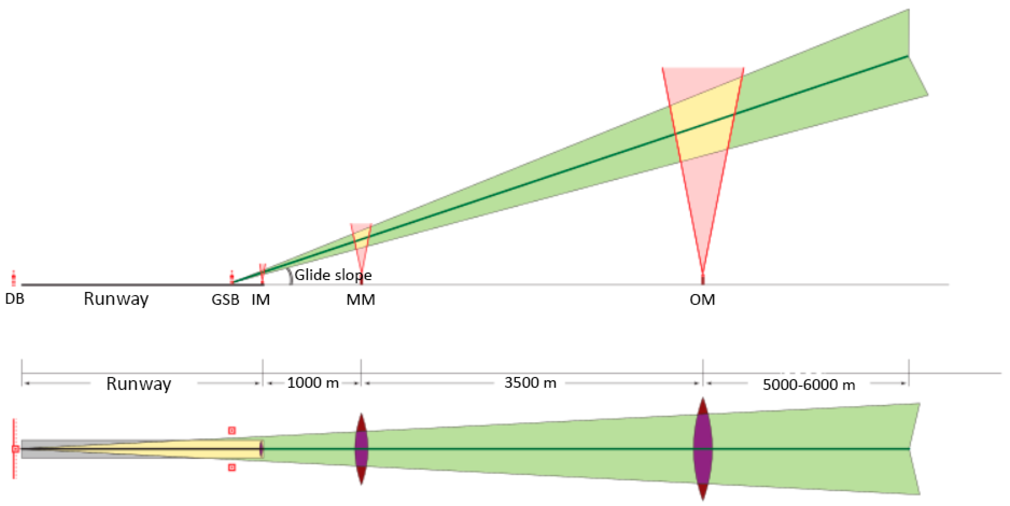
2.1. Instrumental Landing System (ILS)

An ILS [36,37] consists of two main parts: the ground part, that sends the signal, and the airborne part, that receives and processes it. The ground equipment (see Figure 1) includes the following: a directional beacon (DB), glide slope beacon (GSB), inner marker (IM), middle marker (MM), and the outer marker (OM). The aircraft equipment is a set of two radio receivers with directional aerial antennae (the directional one and the glide path one). The directional and glide slope beacons are installed next to the runway: the directional beacon—near the opposite end of the runway along the centerline; the glide slope beacon—on the side of the runway abeam the landing point from the runway threshold.
Flight director systems (that determine the aircraft location relative to the glide path and display it) are sensitive to the signals from the ILS, that are distorted by the various objects in the vicinity, such as houses, hangars, and nearby planes and cars, which can produce significant interference [27]. Ground slopes, hills, and other terrain unevenness, can also reflect the signal and, thus, interfere with the readings. All of these factors show the limits of the ILS’s reliability. For the ILS to function normally [38], additional regulations related to plane movement on the ground have to be implemented.
There exist some factors pertaining to the glide path selection and aircraft descent that limit the utility of the ILS [39,40]. The main limitation is the absence of the optimal glide path for each specific aircraft, which necessitates sticking to a single glide path, with the vertical 3-degree approach slope. Besides that, the location of the glide path beacon and its relatively high frequency make it impossible to factor in the angles of deviation during the final approach phase corresponding with the inner glide path beacon area (in this area, the antenna array radiation pattern is yet to be formed). That is why a radio altimeter is commonly used for landing instead.

2.2. Microwave Landing System (MLS)

The microwave landing system [41,42] was created as a replacement for the ILS, but, as of today, its use in civil aviation is limited only to London’s Heathrow Airport [43]. MLS [44] was developed with the aim of mitigating the interference from the airport-adjacent objects by switching to super-high-frequency (SHF, 3–30 GHz) waves, and by using narrow-width radiation patterns. Additionally, technical advances of the past years made it possible to switch to phased antenna arrays.
At the core of MLS are two angle-measuring beacons [45] (see Figure 2), the first calculates the angle of approach relative to the runway, and the second calculates the angle of the landing aircraft. The operating frequency range for this system is around 5.05 GHz, which allows to use narrow radiation patterns, while keeping their dimensions relatively small. The azimuth transmitter one manages the aircraft course control and transmits information about the system status to the aircraft. The radiation pattern of such stations is, horizontally, a 2-degree fan beam (for a greater accuracy, the angle can be narrowed to 1 degree), while vertically, the fan beam is dozens of degrees wide. The azimuth transmitter two manages the aircraft that is taking off or has missed the approach. This installation is similar to the directional beacon and its functions may be changed when the approach angles are changed. The angle-measuring station 1 (AMS-1) emits the radiation pattern in the form of a vertical 1.5-degree fan beam. Vertically, its range is limited to the visibility range of the azimuth transmitter one. The glide slope angle is selected by the pilot and ranges from 0.9 to 15 degrees. The angle-measuring station 2 (AMS-2) pinpoints the flare moment and handles the aircraft until the touchdown [46].
The disadvantages of that system include its high cost and a great amount of effort for its deployment, especially when there is no required infrastructure to support it.

2.3. Satellite Landing System (SLS)

Approaches relying on satellite navigation are a type of area navigation, meaning navigation that allows an aircraft to choose any course within a network of navigation beacons, within the range of onboard equipment or within a combination of the two [47].
The equipment used in satellite landing systems can be divided into three categories (see Figure 3):
  • Space equipment, that consists of the GPS and GLONASS satellite networks.
  • Ground equipment, a supplementary Ground-Based Augmentation System (GBAS), which enables the differential mode.
  • Airborne equipment, which includes the GNSS (Global Navigation Satellite System) receiver that picks up information from the satellites and local augmentation stations.
It is important to notice that Category 3 is mandatory, while Category 2 is used for improving the accuracy of the system. However, this equipment may be absent if its deployment does not happen to be possible due to any reasons, either technical or funding. The GBAS add-on includes a local augmentation station and a receiver for GPS and GLONASS signals that is placed at the precisely measured (centimeter accuracy) coordinates. Navigation signals emitted by the GNSS are received and processed by the local augmentation stations. After that, the differential corrections, system integrity data, and other service messages are transmitted via a VHF band into the onboard GNSS. With that stated, SLSs do have some serious disadvantages:
  • They are sensitive to weather interference.
  • The antennae might become shadowed by the aircraft structures during maneuvers.
  • The SLS is sensitive to jamming that could limit its effectiveness.
  • The accuracy the SLS provides is insufficient for precision landings.
  • The SLS is incapable of providing accurate measurements of the aircraft altitude.
The precision of the GNSS space equipment fluctuates over time, and the system is prone to occasional lapses in monitoring, that might occur, for instance, when the onboard receivers are switching to different navigation stations. The fact is that the satellites orbiting the Earth and the occasional GNSS errors lead to errors in target location, whose values might change every several hours. Additionally, the precision level of the SLS (95%) fluctuates depending on the constellation geometry. The augmentation stations help rectify most of these errors, but the augmentation stations of today do not meet the criteria for the first ICAO category in accuracy and, more importantly, integrity. Namely, the SLS-x00 augmentation stations by Honeywell meet the requirements for Special Category 1, which has relaxed access to the vertical channel compared to the ICAO Category 1.

3. Algorithm Synthesis

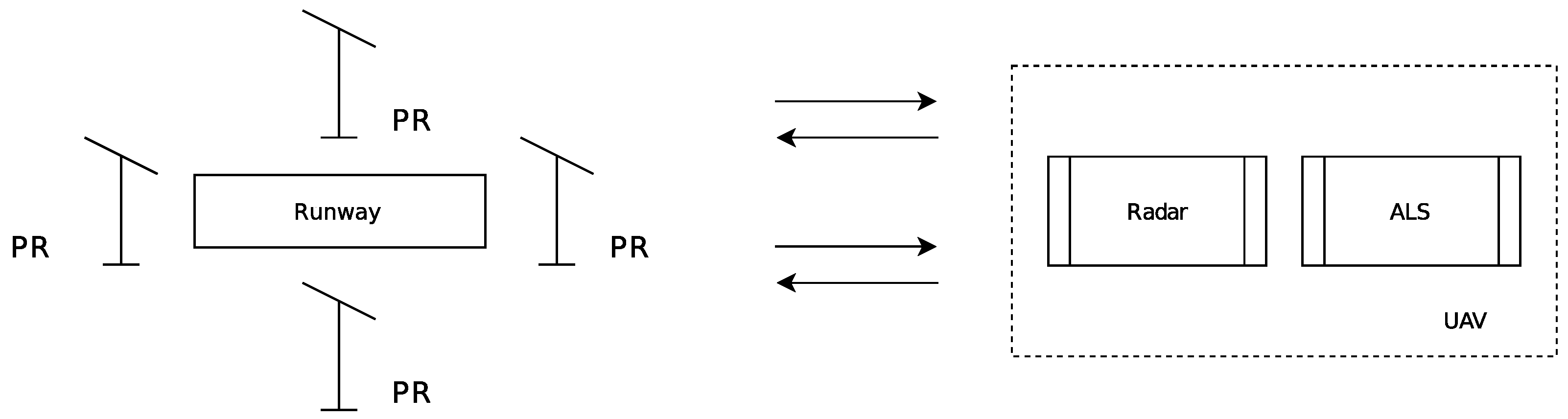
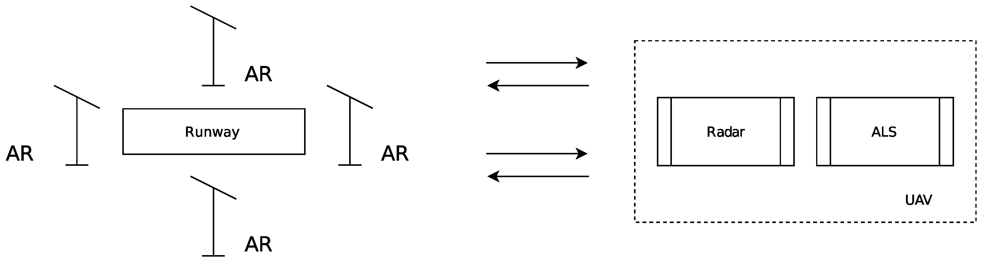
3.1. Concept Description of Using a Radar to Ensure the Aircraft’s Landing

In an autonomous landing system using an onboard radar [48,49], the reference trajectory and its angular deviations can be calculated based on processing signals reflected from special reflectors [50] (passive repeaters). In the most general form, the possible corner placement relative to the runway is shown in Figure 4.
The reference trajectory in the horizontal plane can be formed by signals reflected from corner reflectors placed along the runway axis at some distance from its ends. The current deviations from the runway axis can be calculated from the aircraft position relative to the angles placed at a certain distance from the runway axis. In the absence of guidance errors, the distances from the aircraft to the corners placed on the side of the runway should be equal.
Depending on the number of used reflectors and their locations, a large number of landing options can be implemented. It should be mentioned that, with an increase in the number of used reflectors due to averaging the measurement results, the methodological and fluctuation components of the measurement error can be reduced. At the same time, with an increase in the number of used reflectors, both the time for their installation and the time for preparing the landing place for receiving UAVs increase.
In general, the mutual location of the aircraft and the characteristic points on the runway centerline during the guidance process on which the landing and further mileage are carried out can be implemented in various ways. Using signals reflected from reflectors with known coordinates, the location of the UAV can be determined on the basis of measuring the range to them (time-difference of arrival (TDOA) method) or on the basis of simultaneous measurements of the range to the corner reflectors and onboard bearings (angle of arrival (AOA) method). If the UAV position is estimated with a rather high accuracy using Doppler-inertial or inertial-satellite systems, then the knowledge of the exact coordinates of the reflector corners would not be required any longer.
The choice of a specific method for determining the relative position of the UAV during its landing can be carried out during the simulation. A preliminary analysis has shown that the most acceptable are TDOA and AOA options, for determining the UAV location, using the course method of generating control signals with four corner reflectors. These methods for estimating the UAV location can also be implemented using active repeaters instead of corner reflectors that re-emit and amplify the input signal as shown in Figure 5. This approach allows reducing the required energy potential of the onboard radar during landing, but it requires the creation of power supply networks in the runway area.
Let us further consider the issue of determining the UAV location in the process of it moving down and landing, using ground-based corner reflectors and a UAV radar.

3.2. Principal Solution of the Navigation Problem in Onboard Radar

The location finding method for the UAV during its landing is based on a range measurement location finding of an active user of the navigating system. Let us discuss in more details the two-step algorithm of the location finding for the UAV during its landing with the initial situation shown in Figure 6. A UAV, carrying an airborne radar, has a velocity vector V H and the true height H, according to the autonomous navigation system, approaches the airport area. The reflectors placed on the ground are marked with numbers 1–4. Reflectors one and three are located on the rolling axis of the landing path and reflectors two and three are located on the orthogonal axis drawn through point O, that is the intended point of the UAV touchdown.
The first step of the procedure includes the emission of the probing signals; the receiving of its reflection from the previously positioned reflectors; the calculation of the distances to each reflector, denoted as R 1 , R 2 , R 3 , and R 4 . The vector of the distance measurements obtained as the output of the first step is the input data vector for the second step. The mathematical model of the input data vector can be described in the form of:
y R n , k = R n ( x k , y k , z k ) + ε R n , k
where R n , k is the distance between the radar antenna and the n-th reflector at the observation moment; x k , y k , and z k are the true current coordinates; ε R n , k is the error in measuring the distance R n , k . In the Cartesian coordinate system, with the origin point located at the intended UAV touchdown point on the landing path, the distance between the airborne radar and the n-th reflector can be described as:
y R n , k = ( X n x k ) 2 + ( Y n y k ) 2 + ( Z n z k ) 2 .
where X n , Y n and Z n are the coordinates of the n-th reflector.
The vector of the current relative coordinates of the UAV at the k-th time step is estimated as the solution of the system of nonlinear equations; these equations are the equations of the spheres with reflectors in the centers and the radii equal to the distances to the airborne radar. The linearization procedure is invoked to simplify the system with a priory estimation taken from another system such as an autonomous UAV navigation system. After the appropriate linearization [51] is conducted, the presented system takes the form of:
x ^ k = x ˜ k + H ˜ T H ˜ 1 H ˜ T Δ y R , k ,
where x ^ k is the aircraft coordinate vector estimation at the k-th moment of time, x ˜ k is the prior estimation at the k-th step, H ˜ is the cosine matrix, and Δ y R , k is the vector of the estimation errors.
Figure 7 shows a UAV in the k-th moment of time having the coordinates ( x k , y k ) in a rectangular coordinate system defined by the orthogonal axes X and Y on a plane formed by the UAV’s coordinates and the n-th corner reflectors (CR) C R n . The X-axis was oriented along the runway and all the corner reflectors were located symmetrically.
The cosine matrix H ˜ has the same number of rows as the number of the reflectors and the same number of columns as the number of the estimated coordinates:
H ˜ x ^ k = cos α 1 , k cos β 1 , k cos γ 1 , k cos α 2 , k cos β 2 , k cos γ 2 , k cos α 3 , k cos β 3 , k cos γ 3 , k cos α 4 , k cos β 4 , k cos γ 4 , k .
Each element of the matrix is the cosine of the angle formed by the tangent line to the circle and the appropriate axis of the reference system. The values of the elements of the cosine matrix were determined by the coordinates of the reflectors and the current coordinates of the UAV:
(5) cos α n , k = X n x ^ k R n , k (6) cos β n , k = Y n y ^ k R n , k (7) cos γ n , k = Z n z ^ k R n , k
The cosine matrix H ˜ X ˜ k can also be presented in the form of partial derivatives of the position lines (circles) by the appropriate coordinates:
H ˜ x ^ k = R 1 ( x ^ k ) x R 1 ( x ^ k ) y R 1 ( x ^ k ) z R 2 ( x ^ k ) x R 2 ( x ^ k ) y R 2 ( x ^ k ) z R 3 ( x ^ k ) x R 3 ( x ^ k ) y R 3 ( x ^ k ) z R 4 ( x ^ k ) x R 4 ( x ^ k ) y R 4 ( x ^ k ) z .
There are two main factors that determine the errors of the positioning in TDOA and AOA systems. The first one is the error measuring the distance between the airborne radar and the reflectors ε R n , k . The second is the geometric dilution of precision (GDOP) that represents the expected precision loss in the positioning systems, given the special factors of the mutual disposition of the reflectors and the radar. The value of the GDOP can be estimated [52,53] based on the cosine matrix using:
G D O P k = t r H ˜ T H ˜ 1 1 2
where tr[⁎] stands for the matrix trace. The potentially achievable minimum for the standard deviation of the error n, the estimation of the distance between the reflector and the radar are determined by the spectral width Δ f C K of the probing pulse and the signal-to-noise [54] ratio Q:
ε R = c 2 Δ f C K Q
The real values of the range measurement precision were determined by the properties of the ground, resulting in a multi-ray signal propagation and, therefore, the noise in the correlator output signal, hardware errors, etc.

4. Results

Consider the described landing system’s effectiveness on a specific example of landing an aircraft-type UAV along a trajectory, which the horizontal and vertical sections shown in Figure 8 and the course difference defined as the difference in the y-coordinate (see Figure 3) between the intended touchdown point of the UAV and its position at the k-th observation moment. The trajectory initial height was 35 m, the range to the touch point was 500 m, and the push down angle was 5 degrees. The dots show the reflectors placed for landing UAVs using the radar. Figure 9 shows the runway plan and the reflectors’ locations, indicating the distances between them. The intended touchdown point was the intersection of the runway longitudinal axis and the segment connecting the side reflectors. The model of the landing trajectory and runway were indicative and could be refined for UAV-specific types and landing conditions.
The study of the UAV’s positioning errors occurring along its trajectory is a problem whose analytical solution in closed-formed is extremely difficult. Therefore, we proposed using the simulation of the UAV equipped with an onboard radar during its final approach in the vicinity of the runway. A sequence of coherent radio pulses with a duration of 50 ns was used as a probing signal.
Figure 10 shows the UAV’s push-down trajectory and the marks obtained determining its coordinates by solving Equation (3) for successive moments of time and illustrates errors in the vertical plane (top) and in the horizontal (bottom). As can be seen from the above figures, the errors in the horizontal plane were quite small, and the UAV’s estimated location did not differ from its actual position by more than 1 m. The worst situation was in the vertical plane, where the error values could be up to three meters, an unsatisfactory result. The latter was explained by the large value of the geometric factor (9), connecting the location determination errors with the errors of the distance primary measurements to the reflectors. The geometric factor, in turn, depended on the base of the positional navigation system, that is, on the distance between its reflectors.
Figure 11 shows the total error dependence in determining the UAV’s location in the time from the beginning of the approach to the landing trajectory. Dotted lines represent the raw value of the absolute error and the solid lines account for the Savitzky–Golay filter [55,56] application (open-loop filter of order three). Data were obtained as a result of the numerical simulation for both the default case and the case with one reflector in a higher position. A single simulation was performed and a single realization of the noise vector was generated. That dataset was then processed by the two systems with different reflector heights representing the two presented cases. Thus, no ensemble averaging was employed. The dependency of the location determination error shown in Figure 11 allowed to conclude that, as the UAV approached the calculated landing point, the error values decreased and reached a value of one meter. If such a value was quite acceptable for errors in the planned plane, then, for errors in the vertical plane, such values would not allow a soft landing on the runway.
To reduce vertical errors, one would further consider the reflector height influence located on the edge of the runway opposite to the landing point on the accuracy of estimating the UAV coordinates’ vertical component. Figure 12 and Figure 13 with Figure 11 (black lines) show similar dependencies to Figure 10 with Figure 11 (blue lines) for the height of the above-mentioned reflector of 5 m.
A comparison of the dependencies, shown in Figure 11, allowed to draw the following conclusions: Firstly, an increase in the height of the most distant reflector had little effect on the error’s magnitude in determining the UAV’s location during its push down. The difference in error values was about 10% and, at the final stage, this did not allow to obtain a sufficiently high accuracy of estimating the UAV’s true height. Secondly, at the push-down final stage, after the ninth second, there was a sharp spike in the values of location determination errors, which was unacceptable.

5. Discussion

The results obtained in the course of mathematical modeling made it possible to evaluate the main accuracy operation characteristics of the UAV’s onboard radar during its landing.
The use of angle reflectors placed on the runway plane allowed only an inaccurate landing approach, that is, an approach without an estimate of the true UAV height. To overcome this disadvantage, the following approaches can be used: First, install a low-altitude radio altimeter on the UAV with a measurement range from 0 to 150 m, which allows to specify the true UAV height at the final stage of push down. Secondly, to increase the accuracy of estimating the UAV coordinates, it is advisable, given the sufficiently high level of the one-time measurements dispersion of the current coordinates, to use filtering algorithms for estimating the current location, for example, based on the Kalman filters or α β filters. In addition, information about the required trajectory of the UAV push down during landing can be introduced into the model of these filter’s functions. The third approach is to increase the accuracy of determining the UAV’s location by expanding the band of the probing signal to several tens of megahertz, which would further reduce the errors of primary distance measurements to the reflectors. Furthermore, implementing such a landing method in the coherent mode of UAV radar operation, it is possible to introduce procedures for evaluating the components of the UAV velocity vector into the signal processing algorithms with the further use of the obtained estimations in filtering algorithms for smoothing the estimates of primary systems. To reduce the fluctuation primary measurement components by analogy with satellite radio navigation systems, tracking loops for the delay for the signals of each reflector can be implemented. Given the increase in multipath interference as the height of the UAV’s push down, there is a need for the use of additional algorithms for processing input radio signals and primary distance measurements.

6. Conclusions

The conducted studies of the problem solving the effectiveness of a UAV landing using ground-based reflectors, and its onboard radar, allowed to draw the following main conclusions:
  • Dissimilar to the modern aircraft landing systems, this system did not require the presence of radio engineering devices and a developed infrastructure in the runway area, that makes such systems especially relevant when it is necessary to deploy them quickly, or operate UAVs in poorly developed territories;
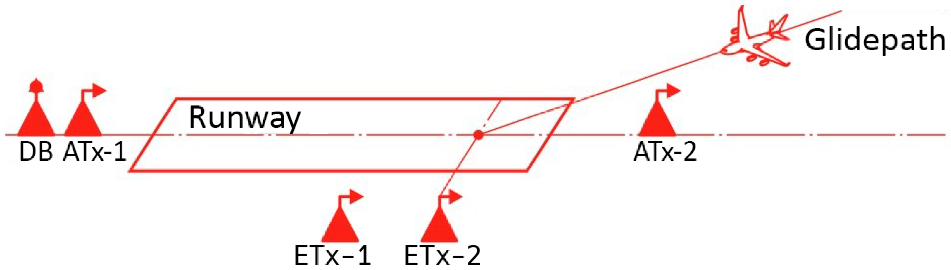
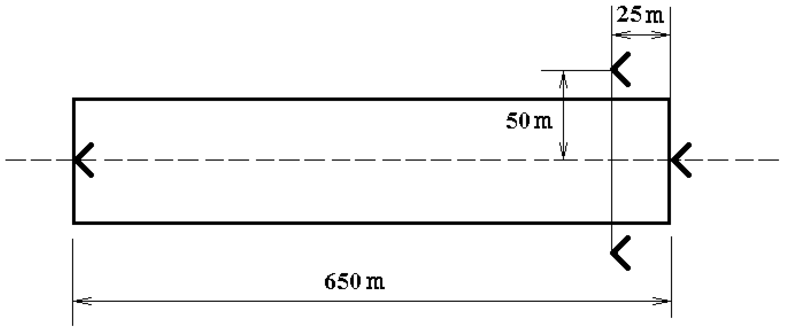
  • The reflectors’ locations in the runway area should be carried out taking into account the estimated landing point and the UAV’s approach trajectory;
  • To ensure errors in estimating the UAV’s location in the horizontal plane, it was enough to provide a base on the side reflectors of about 50 m;
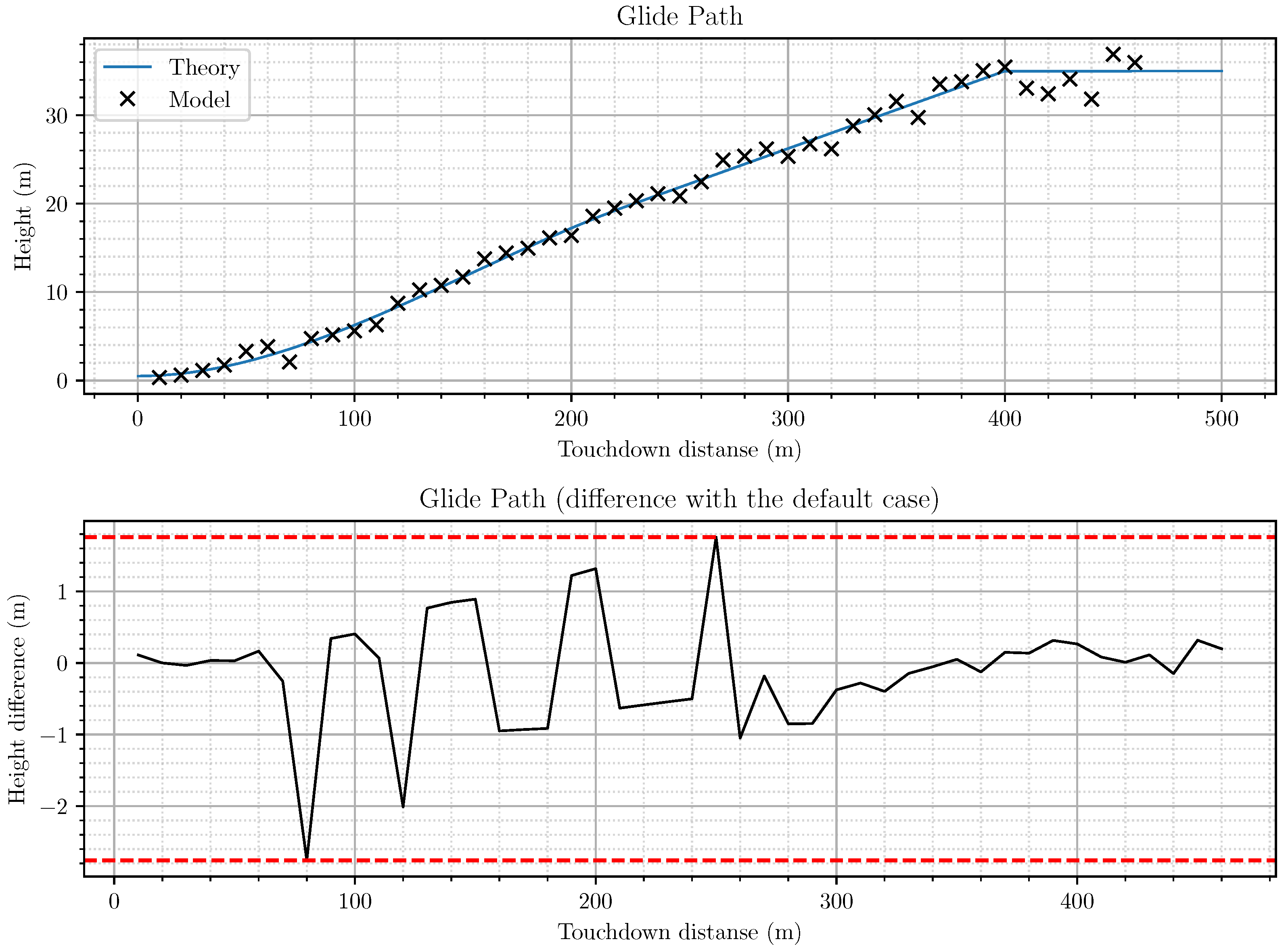
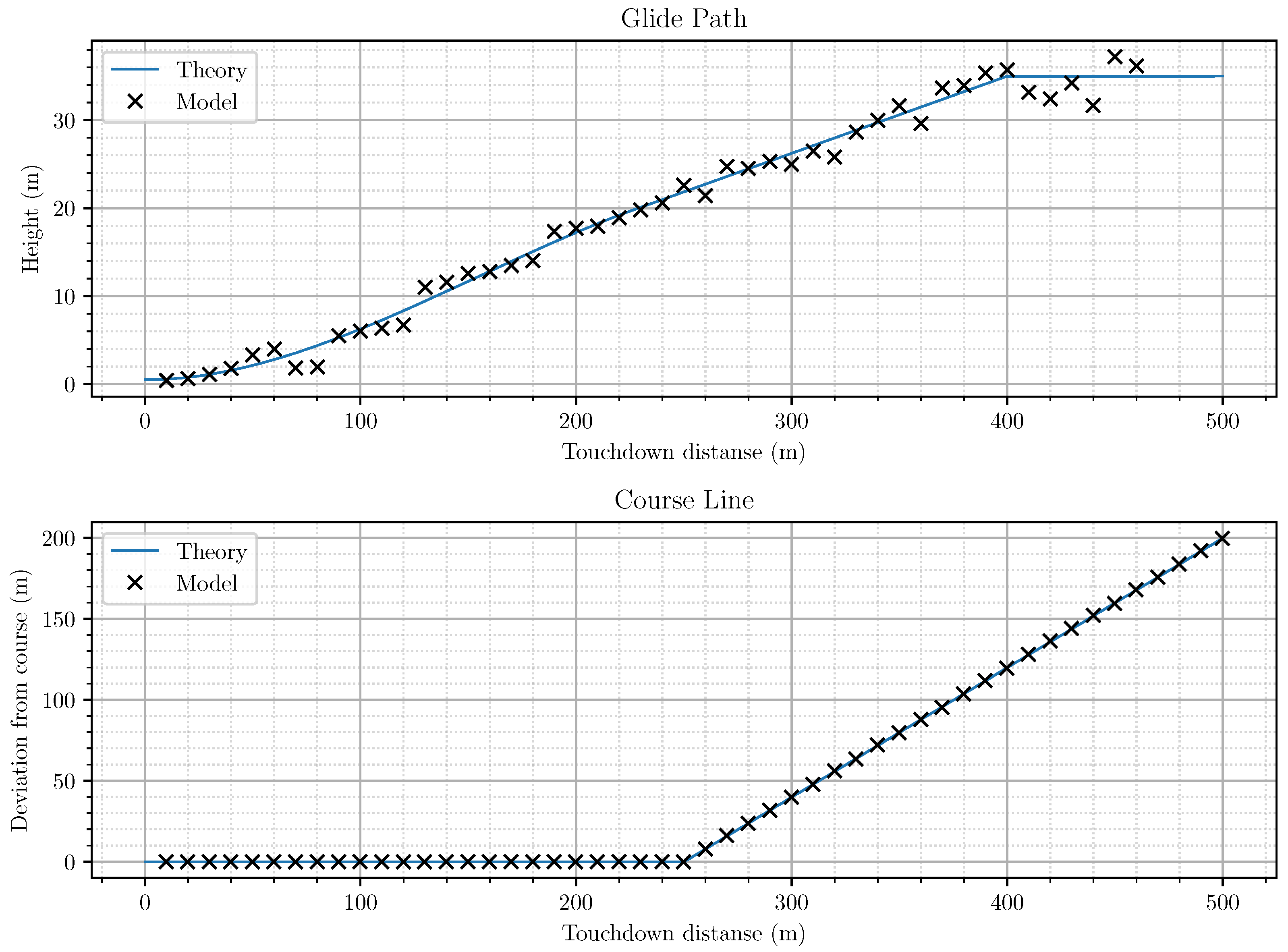
  • All reflectors’ locations in the runway plane did not allow to accurately estimate the UAV’s true height, which was especially critical at the final stage of the UAV’s landing;
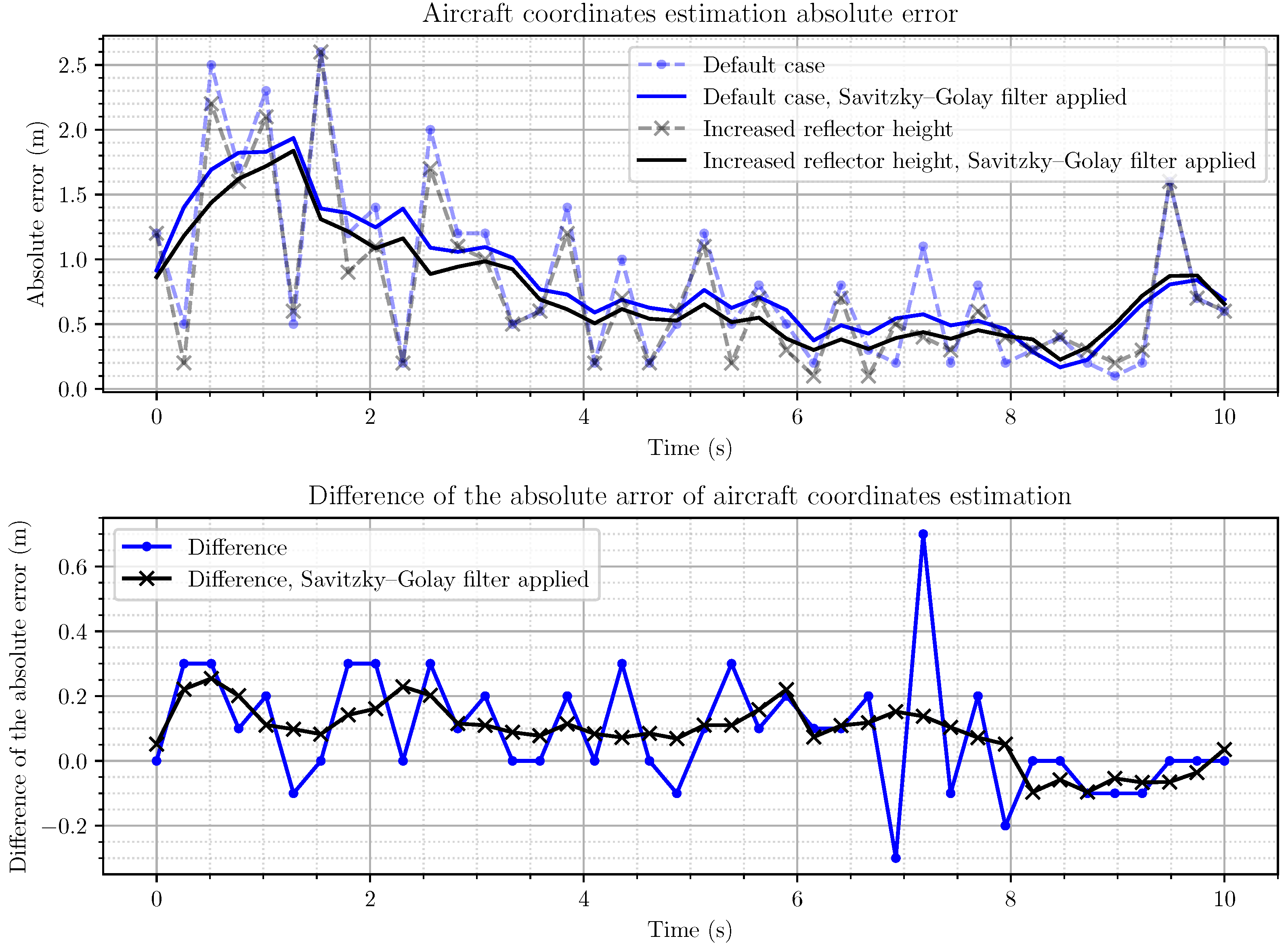
  • Lifting one of the reflectors to a height of up to 20 m did not allow to obtain a significant gain in errors in determining the location and height of the UAV;
  • In order to improve the accuracy of the UAV’s height estimation, it was necessary to use additional algorithms for processing received radio signals and the results of primary measurements.

Author Contributions

Conceptualization, D.Y. and B.T.; methodology, D.Y. and B.T.; software, D.Y. and E.E.; validation, T.S. and E.E.; formal analysis, D.Y. and B.T.; investigation, T.S. and E.E.; resources, E.E.; data curation, D.Y. and E.E.; writing—original draft preparation, D.Y. and E.E.; writing—review and editing, D.Y., T.S., E.E. and B.T.; visualization, E.E.; supervision, D.Y. and B.T.; project administration, T.S.; funding acquisition, D.Y. All authors have read and agreed to the published version of the manuscript.

Funding

This research was funded by the state assignment of the Ministry of Science and Higher Education of the Russian Federation, project no. FSFF-2020-0015.

Institutional Review Board Statement

Not applicable.

Informed Consent Statement

Not applicable.

Data Availability Statement

Not applicable.

Conflicts of Interest

The authors declare no conflict of interest.

References

  1. Hughes, N.H. The influence at ATC considerations on the accuracy required from a future landing guidance system. Tech. Memo. Avion. 1971, 79. [Google Scholar]
  2. Sachs, G. Perspective Predictor/Flight—Path Display with Minimum Pilot Compensation. J. Guid. Control. Dyn. 2000, 23, 420–429. [Google Scholar] [CrossRef]
  3. Hirst, M. The Air Transport System; Woodhead Publishing: Reading, MA, USA, 2008. [Google Scholar]
  4. Salih, A.A.A.A.; Zhahir, A.; Ariff, O.K. Comparative Study on Aircraft Landing Instruments: Accuracies and Limitations. Appl. Mech. Mater. 2012, 225, 549. [Google Scholar] [CrossRef]
  5. Schroer, R. Navigation and landing—A century of powered flight 1903–2003. IEEE Aerosp. Electron. Syst. Mag. 2003, 18, 27–36. [Google Scholar] [CrossRef]
  6. de Haag, M.U. Terrain Referenced Integrity Monitor for an Unmanned Aircraft Systems Precision Approach. In Proceedings of the AIAA/IEEE 39th Digital Avionics Systems Conference (DASC), San Antonio, TX, USA, 11–15 October 2020; pp. 1–10. [Google Scholar] [CrossRef]
  7. Ho, H.W.; Chu, Q. Automatic Landing System of a Quadrotor UAV Using Visual Servoing. In Proceedings of the 2nd CEAS Specialist Conference on Guidance, Navigation and Control, Delft, The Netherlands, 10–12 April 2013; pp. 1264–1273. [Google Scholar]
  8. Bloise, N. A Survey of Unmanned Aircraft System Technologies to enable Safe Operations in Urban Areas. In Proceedings of the 2019 International Conference on Unmanned Aircraft Systems (ICUAS), Atlanta, GA, USA, 11–14 June 2019; pp. 433–442. [Google Scholar] [CrossRef]
  9. Gray, R.; Maybeck, P. An integrated GPS/INS/baro and radar altimeter system for aircraft precision approach landings. In Proceedings of the IEEE 1995 National Aerospace and Electronics Conference, NAECON 1995, Dayton, OH, USA, 22–26 May 1995; Volume 1, pp. 161–168. [Google Scholar] [CrossRef] [Green Version]
  10. Ko, P.Y.; Enge, P.; Powell, J. Continuity improvements via inertial augmentation of GPS-based landing system. In Proceedings of the Position Location and Navigation Symposium—PLANS ’96, Atlanta, GA, USA, 22–25 April 1996; pp. 153–160. [Google Scholar] [CrossRef]
  11. Wang, H.; Diao, M.; Gao, L. Low Probability of Intercept Radar Waveform Recognition Based on Dictionary Leaming. In Proceedings of the 2018 10th International Conference on Wireless Communications and Signal Processing (WCSP), Hangzhou, China, 18–20 October 2018; pp. 1–6. [Google Scholar] [CrossRef]
  12. Hall, T.; Soares, M. Analysis of localizer and glide slope Flight Technical Error. In Proceedings of the IEEE/AIAA 27th Digital Avionics Systems Conference, St. Paul, MN, USA, 9 December 2008; pp. 2–9. [Google Scholar] [CrossRef] [Green Version]
  13. Kayton, M.; Fried, W.R. Landing guidance. In Avionics Navigation Systems, 2nd ed.; John Wiley & Sons: Hoboken, NJ, USA, 1997; pp. 597–641. [Google Scholar]
  14. Korn, B.; Doehler, H. Passive landing aids for precision EVS approach and landing. Digit. Avion. Syst. Conf. 2003, 2, 1–8. [Google Scholar] [CrossRef]
  15. Loss, K.; Nicosia, J.; Taylor, G. Autonomous precision approach and landing system APALS. In Proceedings of the IEEE National Telesystems Conference—NTC ’94, San Diego, CA, USA, 26–28 May 1994; pp. 195–198. [Google Scholar] [CrossRef]
  16. Borst, C.; Mulder, M.; Paassen, M.V.; Mulder, J. Path-oriented control/display augmentation for perspective flight-path displays. J. Guid. Control. Dyn. 2006, 29, 780–791. [Google Scholar] [CrossRef]
  17. Hess, R.A. Unified theory for aircraft handling qualities and adverse aircraft pilot coupling. J. Guid. Dyn. 1997, 20, 1141–1148. [Google Scholar] [CrossRef]
  18. Ma, J.; Huang, G.; Zuo, W.; Wu, X.; Gao, J. Robust radar waveform recognition algorithm based on random projections and sparse classification. IET Radar Sonar Navig. 2014, 8, 290–296. [Google Scholar] [CrossRef]
  19. Ming, Z.; Lutao, L.; Ming, D. LPI Radar Waveform Recognition Based on Time-Frequency Distribution. Sensors 2016, 16, 1682–1701. [Google Scholar]
  20. Roberge, V.; Tarbouchi, M.; Labonte, G. Comparison of Parallel Genetic Algorithm and Particle Swarm Optimization for Real-Time UAV Path Planning. Ind. Inform. IEEE Trans. 2013, 9, 132–141. [Google Scholar] [CrossRef]
  21. Shevgunov, T. Using artificial neural networks for time difference of arrival target localization based on reduced discrete cosine transform. Period. Tche Quim. 2019, 16, 530–540. [Google Scholar] [CrossRef]
  22. Shevgunov, T.; Vavilova, Z.; Guschina, O.; Efimov, E. Heuristic Global Optimization Algorithm for Estimating a Radio Source Location by a Passive Radar System. TEM J. 2020, 9, 427–433. [Google Scholar] [CrossRef]
  23. Liu, G.; Gu, H.; Su, W.; Sun, H. The analysis and design of modern Low Probability of Intercept radar. In Proceedings of the 2001 CIE International Conference on Radar Proceedings (Cat No.01TH8559), Beijing, China, 15–18 October 2001; pp. 120–124. [Google Scholar] [CrossRef]
  24. Chen, H.; Wang, X.; Li, Y. A Survey of Autonomous Control for UAV. In Proceedings of the 2009 International Conference on Artificial Intelligence and Computational Intelligence, Shanghai, China, 7–8 November 2009; pp. 267–271. [Google Scholar] [CrossRef]
  25. Dougherty, J.; Lee, D.; Lee, T. Laser-based guidance of a quadrotor uav for precise landing on an inclined surface. In Proceedings of the 2014 American Control Conference, Portland, OR, USA, 4–6 June 2014; pp. 1210–1215. [Google Scholar] [CrossRef]
  26. Kaloshin, G.A. Scientific fundamentals of laser aids for low visibility approach landing of aircraft. Technical Digest. CLEO/Pacific Rim 2001. In Proceedings of the 4th Pacific Rim Conference on Lasers and Electro-Optics (Cat. No.01TH8557), Chiba, Japan, 15–19 July 2001. [Google Scholar] [CrossRef]
  27. Schleher, D. Low probability of intercept radar. In Proceedings of the IEEE 1985 International Radar Conference, Arlington, VA, USA, 6–9 May 1985; pp. 346–349. [Google Scholar]
  28. Shevgunov, T.; Dubrovin, A.; Nikishov, V. Next-Generation Landing System Based on Combined Passive Radar. In Proceedings of the XXXI General Assembly of the International Union of Radio Science (URSI GASS 2014), Beijing, China, 16–23 August 2014. [Google Scholar] [CrossRef]
  29. Salih, A.A.A.A.; Ariff, O.K.; Zhahir, A.; Ahmad, M.T. Modeling and simulation of a high accurate aircraft ground-based positioning and landing system. In Proceedings of the Space Science and Communication (IconSpace) 2013 IEEE International Conference on, Melaka, Malaysia, 1–3 July 2013; pp. 324–330. [Google Scholar] [CrossRef]
  30. Anderson, E.; Fannin, T.; Nelson, B. Levels of Aviation Autonomy. In Proceedings of the 2018 IEEE/AIAA 37th Digital Avionics Systems Conference (DASC), London, UK, 23–27 September 2018; pp. 1–8. [Google Scholar] [CrossRef]
  31. Brooker, G.; Carter, T. A Millimetre Wave Radar Sensor for Autonomous Navigation and Landing. In Proceedings of the Australian Conference on Robotics and Automation, Melbourne, Australia, 30 August–1 September 2000; pp. 59–64. [Google Scholar]
  32. Gui, Y.; Guo, P.; Zhang, H.; Lei, Z.; Zhou, X.; Du, J.; Yu, Q. Airborne Vision-Based Navigation Method for UAV Accuracy Landing Using Infrared Lamps. J. Intell. Robot. Syst. 2013, 72, 197–218. [Google Scholar] [CrossRef]
  33. Mercado-Ravell, D.A. Autonomous Navigation and Teleoperation of Unmanned Aerial Vehicles Using Monocular Vision. Ph.D. Thesis, Université de Technologie de Compiègne, Guanajuato, Mexico, 2015. [Google Scholar]
  34. Kong, W.; Zhou, D.; Zhang, Y.; Zhang, D.; Wang, X.; Zhao, B.; Yan, C.; Shen, L.; Zhang, J. A ground-based optical system for autonomous landing of a fixed wing UAV. In Proceedings of the 2014 IEEE/RSJ International Conference on Intelligent Robots and Systems, Chicago, IL, USA, 14–18 September 2014; pp. 4797–4804. [Google Scholar] [CrossRef]
  35. Kong, W.; Hu, T.; Zhang, D.; Shen, L.; Zhang, J. Localization Framework for Real-Time UAV Autonomous Landing: An On-Ground Deployed Visual Approach. Sensors 2017, 17, 1437. [Google Scholar] [CrossRef] [Green Version]
  36. Jackson, W.E. Status of instrument landing systems. Proc. IRE 1938, 26, 681–699. [Google Scholar] [CrossRef]
  37. Kramar, E. Instrument landing systems. Interavia 1972, 27, 246. [Google Scholar]
  38. Poritzky, S. Seeking a new precision approach and landing system—A test of maturity. In Proceedings of the American Institute of Aeronautics and Astronautics, 2nd Aircraft Design and Operations Meeting, Los Angeles, CA, USA, 20–22 July 1970. [Google Scholar]
  39. Barbieri, G.G.M.; Claudio, E.D.D.; Parisi, R. Sensor arrays for improved instrumental landing systems. In Proceedings of the 2000 IEEE Sensor Array and Multichannel Signal Processing Workshop, SAM 2000 (Cat. No.00EX410), Cambridge, MA, USA, 17 March 2000; pp. 530–534. [Google Scholar] [CrossRef]
  40. Sanders, L.; Fritch, V. Instrument Landing Systems. IEEE Trans. Commun. 1973, 21, 435–454. [Google Scholar] [CrossRef]
  41. Viret, C. Microwave aircraft digital guidance equipment—Description of the system. In Proceedings of the Electronics and Civil International Conference, Paris, France, 26–30 June 1972; pp. 987–1002. [Google Scholar]
  42. Lanman, M.H. An Investigation of Microwave Landing System Signal Requirements for Conventionally Equipped Civilian Aircraft; Transportation Systems Center: Cambridge, MA, USA, 1971. [Google Scholar]
  43. Cherry, G.W.; MacKinnon, D.; Dewolf, B. Increasing airport capacity and terminal area safety by means of the scanning beam instrument landing system. Trans. Instrum. Soc. Am. 1971, 10, 67–82. [Google Scholar]
  44. Hughes, N.H.; Watling, K.; Harlow, R.A.; Smith, M.E. A Study of the Interface between Air Traffic Control and the Microwave Landing System; Federal Aviation Administration, Systems Research and Development Service: Washington, DC, USA, 1972. [Google Scholar]
  45. Khatun, M.; Mehrpouyan, H.; Matolak, D.; Guvenc, I. Millimeter wave systems for airports and short-range aviation communications: A survey of the current channel models at mmWave frequencies. In Proceedings of the 2017 IEEE/AIAA 36th Digital Avionics Systems Conference (DASC), St. Petersburg, FL, USA, 17–21 September 2017; pp. 1–8. [Google Scholar] [CrossRef] [Green Version]
  46. Dubrovin, A.; Nikishov, V.; Shevgunov, T. Combined AOA/TDOA Passive Radar for Airport Landing System. In Proceedings of the Tyrrhenian International Workshop on Digital Communication: Enhanced Surveillance of Aircraft and Vehicles (ESAV-2014), Rome, Italy, 15–16 September 2014; pp. 87–92. [Google Scholar] [CrossRef]
  47. Johnson, W.A.; McRuer, D.T. Development of a Category II Approach System Model; National Aeronautics and Space Administration: Washington, DC, USA, 1969. [Google Scholar]
  48. Efimov, E.; Shevgunov, T.; Valaytite, A.; Sadovskaya, E. Artificial Neural Network Based Signal Processing for Perspective Onboard Systems. In Proceedings of the 29th Congress of International Council of the Aeronautical Sciences (ICAS-2014), St. Petersburg, Russia, 7–12 September 2014. [Google Scholar]
  49. Efimov, E.; Shevgunov, T. Radar Target Identification Based on Feature Extraction Performed with RBF Artificial Neural Networks. In Proceedings of the XXXI General Assembly of the International Union of Radio Science (URSI GASS 2014), Beijing, China, 16–23 August 2014. [Google Scholar] [CrossRef]
  50. Vladimir, L.O. A Tactical Aircraft Landing Aid. IEEE Trans. Aerosp. Electron. Syst. 1966, 2, 679–684. [Google Scholar] [CrossRef]
  51. Zekavat, R.; Buehrer, R.M. Handbook of Position Location: Theory, Practice, and Advances; Wiley-IEEE Press: Reading, MA, USA, 2019. [Google Scholar]
  52. Guochang, X. GPS. Theory, Algorithms and Application; Springer: Berlin/Heidelberg, Germany, 2003. [Google Scholar]
  53. Parkinson, B.; Spilker, J. Global Positioning System: Theory and Application; AIAA. Inc.: Reston, VA, USA, 1996; Volume 1. [Google Scholar]
  54. Artyushenko, V.; Volovach, V.; Vasilevich, I. Estimation of the Effect of Multiplicative Noise on Signal Detection against the background of Additive Noise. In Proceedings of the 2020 Moscow Workshop on Electronic and Networking Technologies (MWENT), Moscow, Russia, 9–11 June 2020; pp. 1–6. [Google Scholar] [CrossRef]
  55. Schafer, R.W. What Is a Savitzky-Golay Filter? [Lecture Notes]. IEEE Signal Process. Mag. 2011, 28, 111–117. [Google Scholar] [CrossRef]
  56. Candan, Ç.; Inan, H. A unified framework for derivation and implementation of Savitzky–Golay filters. Signal Process. 2014, 104, 203–211. [Google Scholar] [CrossRef]
Figure 1. Glide-path-forming principle in ILS with the schematic positions.
Drones 05 00137 g001
Figure 2. The contents and the disposition of the elements in MLS with directional beacon (DB), azimuthal station transmitter (ATx), and elevation station transmitter (ETx).
Drones 05 00137 g002
Figure 3. The principle of the position determination in SLS.
Drones 05 00137 g003
Figure 4. Landing system structure using the aircraft’s onboard radar.
Drones 05 00137 g004
Figure 5. The system with active reflectors (repeaters).
Drones 05 00137 g005
Figure 6. The principle of the estimation of the coordinated steps during the aircraft landing.
Drones 05 00137 g006
Figure 7. Disposition of the corner reflectors and the UAV.
Drones 05 00137 g007
Figure 8. Gliding line model.
Drones 05 00137 g008
Figure 9. Landing system reflector location.
Drones 05 00137 g009
Figure 10. Mark deviations from the calculated trajectory in the vertical plane (top) horizontal plane (bottom).
Drones 05 00137 g010
Figure 11. Dependency of the absolute error of the aircraft coordinates estimation on time.
Drones 05 00137 g011
Figure 12. Marks deviations from the calculated trajectory in the vertical plane.
Drones 05 00137 g012
Figure 13. Marks deviations from the calculated trajectory in the horizontal plane.
Drones 05 00137 g013
Publisher’s Note: MDPI stays neutral with regard to jurisdictional claims in published maps and institutional affiliations.

