Article

A Monocular Vision Obstacle Avoidance Method Applied to Indoor Tracking Robot

1
Centre for Chemicals Application Technology, China Agricultural University, Beijing 100193, China
2
College of Agricultural Unmanned System, China Agricultural University, Beijing 100193, China
3
College of Science, China Agricultural University, Beijing 100193, China
4
College of Engineering, China Agricultural University, Beijing 100193, China
5
School of Instrument Science and Engineering, Southeast University, Nanjing 210096, China
*
Author to whom correspondence should be addressed.
Drones 2021, 5(4), 105; https://doi.org/10.3390/drones5040105
Submission received: 26 August 2021 / Revised: 17 September 2021 / Accepted: 22 September 2021 / Published: 26 September 2021
(This article belongs to the Special Issue Conceptual Design, Modeling, and Control Strategies of Drones)

Abstract

:
The overall safety of a building can be effectively evaluated through regular inspection of the indoor walls by unmanned ground vehicles (UGVs). However, when the UGV performs line patrol inspections according to the specified path, it is easy to be affected by obstacles. This paper presents an obstacle avoidance strategy for unmanned ground vehicles in indoor environments. The proposed method is based on monocular vision. Through the obtained environmental information in front of the unmanned vehicle, the obstacle orientation is determined, and the moving direction and speed of the mobile robot are determined based on the neural network output and confidence. This paper also innovatively adopts the method of collecting indoor environment images based on camera array and realizes the automatic classification of data sets by arranging cameras with different directions and focal lengths. In the training of a transfer neural network, aiming at the problem that it is difficult to set the learning rate factor of the new layer, the improved bat algorithm is used to find the optimal learning rate factor on a small sample data set. The simulation results show that the accuracy can reach 94.84%. Single-frame evaluation and continuous obstacle avoidance evaluation are used to verify the effectiveness of the obstacle avoidance algorithm. The experimental results show that an unmanned wheeled robot with a bionic transfer-convolution neural network as the control command output can realize autonomous obstacle avoidance in complex indoor scenes.

1. Introduction

Unmanned ground vehicles (UGVs) are often used in the field of unmanned operation, especially in repetitive and single-factory environments [1,2]. Unmanned ground vehicles have also been gradually applied to the indoor environment. In particular, the tracking security unmanned vehicles in indoor public places are widely used [3]. In recent years, the application of unmanned tracking vehicles in building wall monitoring has also been proposed [4]. As shown in Figure 1, the unmanned vehicle regularly inspects the building wall through the sensor according to the specified track and uses the sensor information to evaluate the building safety. However, in the complex indoor environment, unmanned vehicles often encounter obstacles not indicated in the built-in map during operation. How to sense obstacles in time and avoid obstacles is a hot issue in the research of indoor tracking unmanned vehicles. Indoor obstacle avoidance research focuses on perception and control decision-making. Firstly, the local environment is obtained by the sensor and the obstacles are identified, then the obstacle avoidance decision is given by the decision system, and finally, the unmanned vehicle is controlled to complete the obstacle avoidance process.
In the research of the obstacle perception of ground unmanned vehicles, vision sensors, lidar sensors, and millimeter wave radar sensors are usually used to obtain obstacle information. Rajashekaraiah et al. (2017) [5] used a laser rangefinder to obtain obstacle data and constructed a PTEM (probabilistic thread exposure map), which obtained obstacle information through lidar and updated PTEM in real time to guide unmanned vehicles to avoid obstacles. Similarly, using the radar sensor, Yang et al. (2017) [6] proposed the sensor lidar to detect the obstacles in the front path. Based on the lidar data, combined with the vehicle position, obstacle position, vehicle operation capability, and global environmental restrictions, the optimized path was generated, and the path was updated in real time through the detection data. Bhave et al. (2019) [7] applied the laser rangefinder to an unmanned ground vehicle (‘the rover’). The test showed that the unmanned vehicle can detect obstacles in front and navigate back to the base. This unmanned vehicle has been applied to aid intelligence, surveillance, and rehabilitation missions in adult environments. Khan et al. (2017) [8] proposed a disparity image method based on the vision method. This method inferred the relationship between obstacles and robot path through vision and judged the contour and position of obstacles based on projection information. The author’s experiments showed that under the action of visual perception, the robot could detect obstacles of any size and shape within 80–200 cm. Levkovits-Scherer et al. (2019) [9] used the visual perception method for obstacle avoidance tasks, but the application object was UAV. The front environment information of UAV was obtained through monocular vision, and the image was transmitted to the ground control station. The ground control station had a built-in convolution neural network algorithm to extract obstacle information, and then transmitted the flight control command to the UAV to realize real-time obstacle avoidance. Similarly, using visual perception to avoid obstacles, Yu et al. (2020) [10] proposed an autonomous obstacle avoidance scheme based on the fusion of millimeter wave radar and monocular camera, and through extended Kalman filter (EKF) data fusion to build exact and real 3D coordinates of the obstacles. Eppenberger et al. (2020) [11] also used noise point cloud data generated by stereo cameras to divide obstacles into static and dynamic. The moving speed of dynamic obstacles was estimated and a two-dimensional moving grid for obstacle avoidance was generated. The author evaluated them in indoor and outdoor environments, respectively. Finally, the accuracy of dynamic obstacles was 85.3% and that of static obstacles was 96.9%.
In the research of obstacle decision-making and control of unmanned ground vehicles, many path optimization algorithms and intelligent control methods have been adopted. Lv et al. (2021) [12] proposed a fuzzy neural network objective avoidance algorithm based on multi-sensor information fusion and verified the superiority and reliability of the algorithm through simulation and real platform experiments. Hu et al. (2020) [13] divided obstacles into dynamic and static. For static obstacles, the optimal path was generated online by an optimal path reconfiguration based on direct collocation method. For dynamic obstacles, receding horizon control was used for real-time path optimization. The continuous time model predictive control algorithm and the disturbance estimation based on extended state observer were designed. Finally, the simulation experiment was carried out on CarSim platform. Mohamed et al. (2018) [14] proposed an artificial potential field (APF) method combined with optimal control theory for path planning. This method generated a collision-free path when obstacles existed. Based on the artificial potential field method, Chen et al. (2021) [15] proposed an improved artificial potential field for obstacle avoidance of unmanned vehicles in urban environment and solved the problem of autonomous obstacle avoidance in complex urban environment by establishing the models of gravitational potential field, repetitive potential field, and comprehensive potential field. Singla et al. (2019) [16] proposed a UAV obstacle avoidance method based on reinforcement learning. By using recurrent neural networks with temporary attention, UAVs could avoid obstacles in real time when only equipped with a monocular camera.
In this paper, based on the above research on the perception and decision control of unmanned ground vehicles, an end-to-end obstacle avoidance method for unmanned ground vehicles is proposed. The front data of unmanned vehicle are obtained by the monocular vision method, and it is well-applied in the field of intelligent perception based on deep learning [17,18,19] to realize the perception and discrimination of obstacle orientation. The obstacle avoidance strategy is designed based on the output confidence of the neural network to realize the autonomous obstacle avoidance of ground unmanned vehicles in indoor environments. At the same time, aiming at the training of a transfer neural network, this paper innovatively puts forward the bionic optimization method, which realizes the automatic adjustment of neural network learning rate by combining the bionic optimization strategy with transfer training. The main contributions of this work are:
(1) A bat optimization algorithm with an improved time factor is proposed. It improves the search ability of the algorithm in the early iteration stage and the mining ability in the late iteration stage.
(2) The improved bat algorithm is used to optimize the learning rate parameters of the transfer layer. The output of neural network with higher accuracy under the condition of small samples is realized.
The rest of the paper is organized as follow. Section 2 introduces the automatic acquisition of training samples. In Section 3, the improved bat algorithm is used to optimize the neural network. In Section 4, the neural network training and experiments in different scenes are carried out. Section 5 concludes the paper.

2. Materials and Methods Training Set and Test Set Acquisition

Training the transfer convolutional neural network is a kind of supervised learning. Training the neural network requires a large number of annotated images, and manual classification takes time and effort. In this paper, the camera array is arranged in the front, right-front, and left-front of the wheeled robot for image collection. By manually controlling the wheeled robot to move through complex office areas, images from each camera will be automatically classified to avoid manual marking. The images collected by the left-front camera are all obstacles on the left side of the field of vision. The wheeled robot needs to turn right. The images collected by the middle camera are wide vision in front, and the robot needs to walk straight. The image collected by the camera on the right front is the obstacle on the right side of the field of vision, and the wheeled robot needs to turn left.

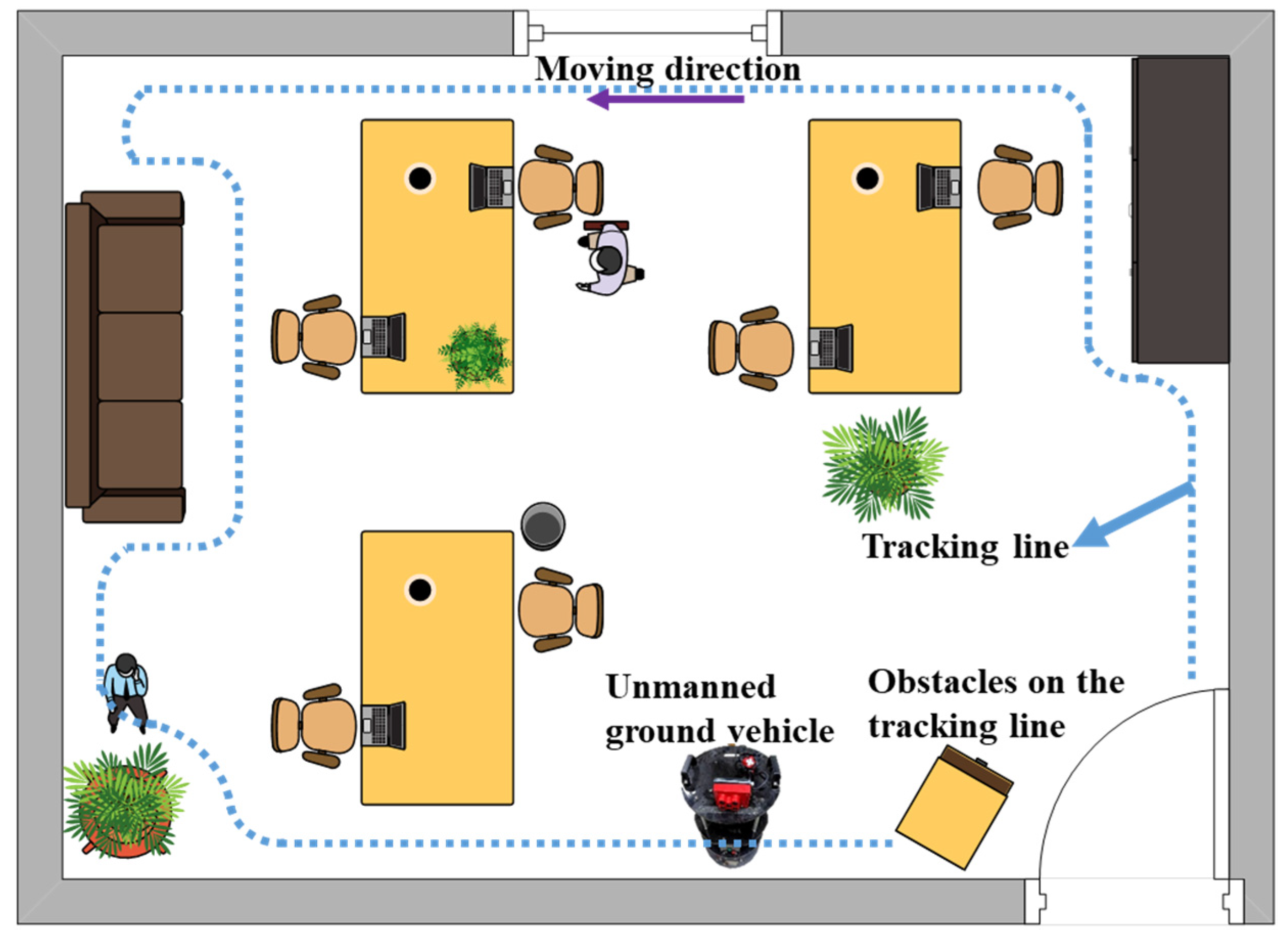
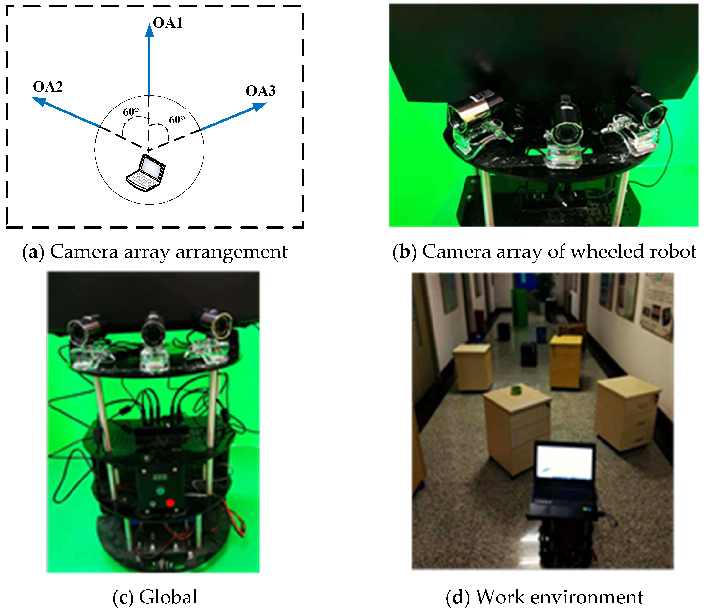
2.1. Video Stream Acquisition

The external AONI camera of the notebook was used for image acquisition. Camera parameters are shown in Table 1.
The arrangement of cameras is shown in Figure 2a,b. OA represents the optical axis of the camera. The three cameras are at an angle of 60° to each other. By manually controlling the wheeled robot through a complex environment, the three cameras separately store the captured video. In the process of progress, the video captured by camera 1 is a straight-through video, the video captured by camera 2 is a video that needs to be turned right (the obstacle is located to the left of the field of view), and the video captured by camera 3 is a left-turn video (the obstacle is located to the right of the field of view). Figure 2c,d shows the image environment acquired by the wheeled robot.
Videos are collected through 4 groups of different experiments, and the duration of videos is 45 min.

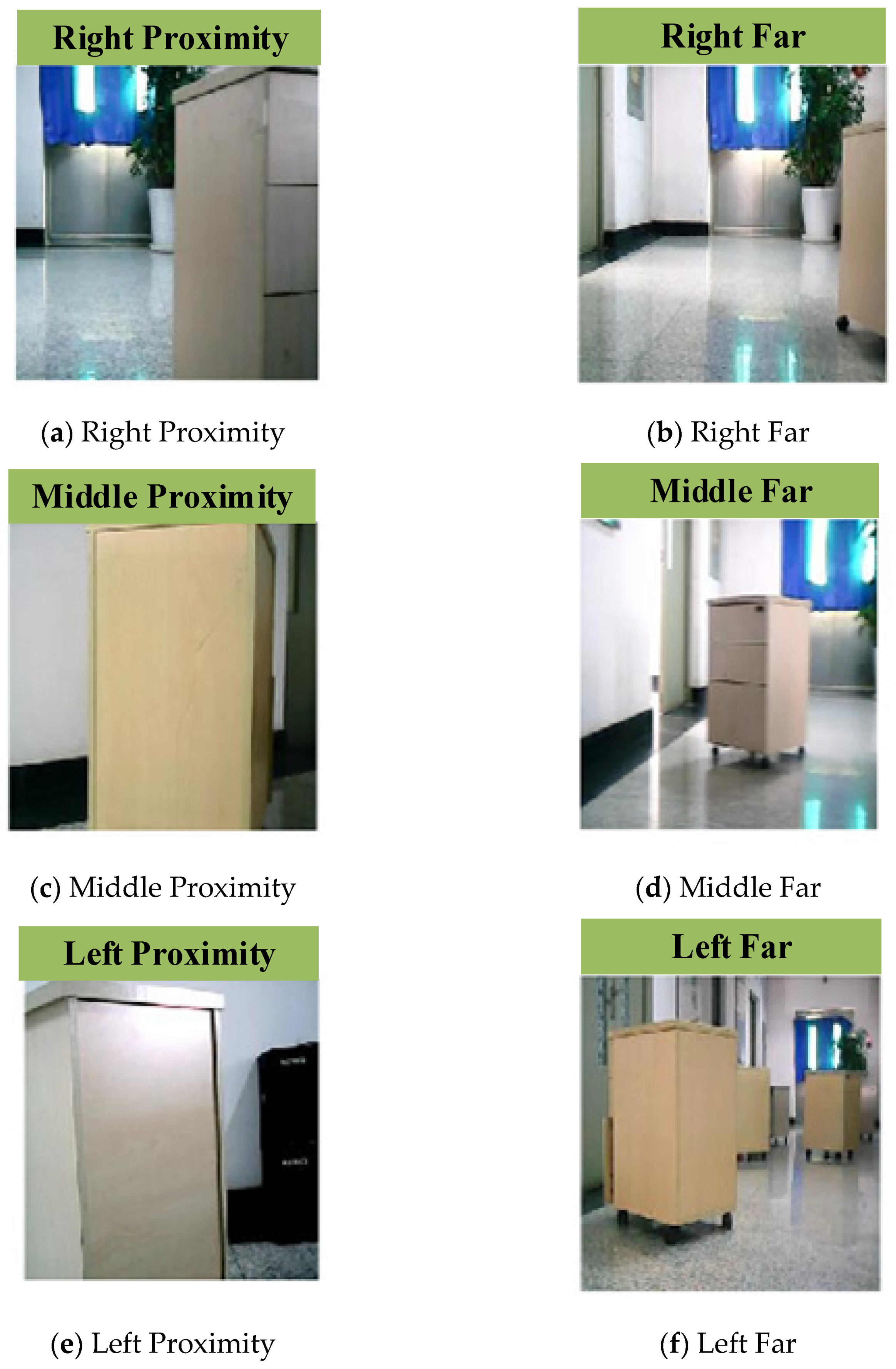
2.2. Data Set Acquisition

The collected video is processed by Matlab, and an image is taken every 20 frames. Since the input of the neural network is 227 × 227, the image needs to be cut to that size. There will be fuzzy pictures in video obtained from each camera, and it is necessary to manually select and remove the fuzzy pictures. The types of collected images are shown in Figure 3, and the number of samples and labels are shown in Table 2.

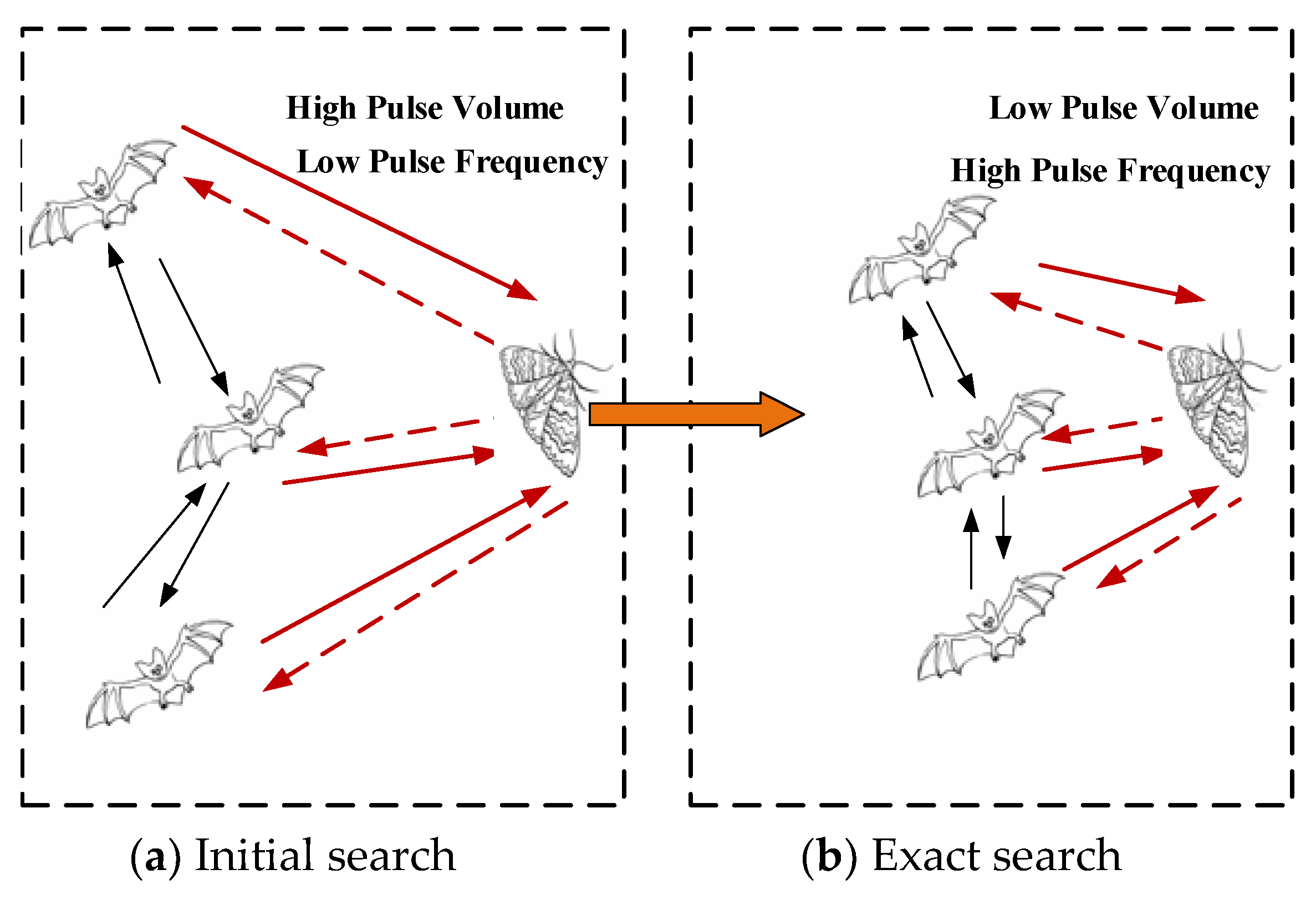
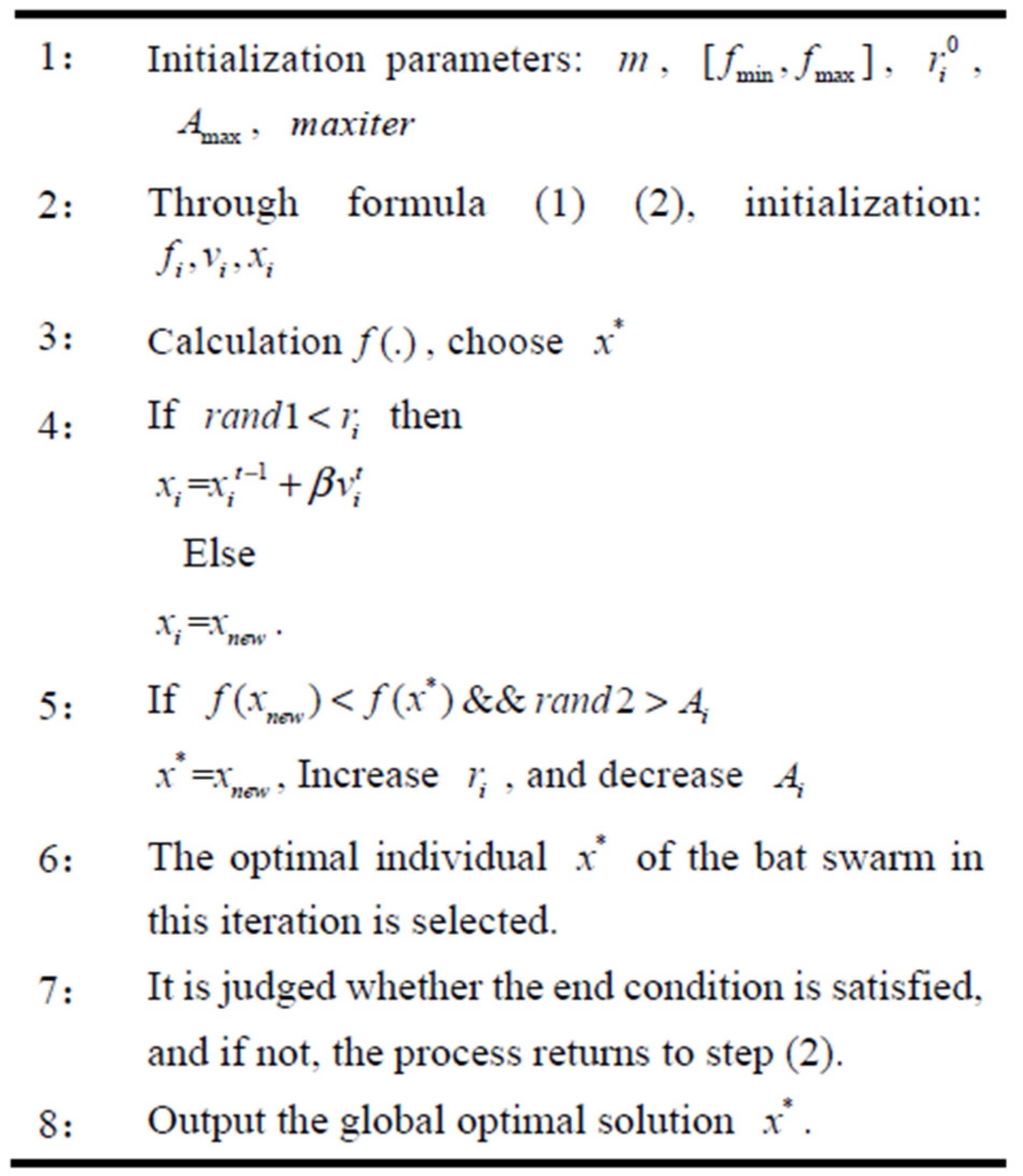
3. Bionic Optimization Neural Network

This paper uses Alexnet-based transfer learning to modify the Alexnet network to accommodate new classification tasks. Alexnet was proposed by Alex in 2012. The Alexnet used in this paper has received training for a total of 1 million images in 1000 categories, including keyboards, pencils, and many animals. Through the training of massive pictures, the first few layers of Alexnet can extract rich features in pictures. When using the first layers and adding new layers of Alexnet to adapt to the output of wheeled robot control direction, it is necessary to fine-tune the transfer-layer and quickly adjust the new layer in the process of training the neural network. Therefore, for the learning rate factor setting of the network layer, the new layers need to set a large learning rate factor parameter, and the transfer layers need to set a small learning rate factor parameter. In the process of training the transfer neural network using the Matlab framework, the Matlab defaults to 1 for the new layers’ weight and bias of learning rate factor. This causes the neural network to train slowly, not to converge quickly, or to fall into local optimum. If the manual adjustment parameters set an excessive learning factor, this causes the loss function to oscillate back and forth at the optimal position during the neural network training and may skip the global optimization. The bionic optimization algorithm is used to optimize the weights and bias learning rate factor parameters in the newly added layer of the transfer neural network. The optimization idea is to obtain the optimal learning rate factor parameter combination by training optimization on the small sample training set, and then applying it to the large sample training set to train the neural network.
The bat algorithm (BA) was proposed by X.S. Yang, a Cambridge scholar, in 2010 to simulate the behaviour of bat echolocation in food exploration [20]. In the process of searching for food, bats first use large pulse sound and low pulse frequency to perform large-scale searches because the strong pulse sound helps to spread ultrasound over a longer distance. When approaching food, low pulse sound and high pulse frequency are used, because high pulse frequency helps to accurately grasp the position of prey. The process of finding food in bats is shown in Figure 4.
In this paper, a time factor improvement method is proposed for the shortcomings of the initial bat algorithm with a small search range in the early stage and insufficient mining ability in the later stage. By adding time factor perturbation to the position update equation instead of the implied time factor with constant 1, the overall search ability of the algorithm is improved. The time factor disturbance Formula (3) and the improved position update Formula (4) are as follows:
(1) The pulse frequency of a bat individual while exploring a target:
f i = f min + ( f max + f min ) × r a n d
where f i is the pulse frequency of the first i individual to explore the target, f min and f max are the upper and lower limits of the pulse frequency, and r a n d is a random number between 0 and 1.
(2) The velocity of individual bats in searching for targets:
v i t = v i t 1 + ( x i t 1 x ) × f i
Among them, v i t and v i t 1 are the flight velocities of the first i individual at time t and time t 1 , respectively. x i t 1 is the position of the bat individual i at time t 1 . x is the current optimal position.
(3) The update of the bats’ positions:
β = 1 + sin ( π 2 π t 2 t max )
x i t = x i t 1 + β v i t
where t is the current number of iterations and t max is the maximum number of iterations.
(4) The update of the pulse frequency and volume of the bat individual when searching for prey:
r i t + 1 = r i 0 ( 1 e γ t )
A i t + 1 = α A i t
where r i 0 is the maximum pulse frequency, γ is an increase parameter of the pulse frequency and is a constant greater than zero, A i t is the pulse volume of the individual i at time t , and α is the pulse volume reduction parameter which is a constant from 0 to 1.
Figure 5 shows the iterative process of bat algorithm. The parameters of the newly added full connection layer weights and the bias learning rate factor are, respectively, set by using bat algorithm, and the parameters of the bat algorithm are set as shown in Table 3.
In the experiment, the improved bat algorithm and the unimproved bat algorithm are compared. Each experimental iteration is 20 times, and each algorithm has two groups of experiments. The accuracy of the neural network trained by the learning rate factor obtained by each optimization iteration is used as a fitness function. The idea of optimization in this paper is to optimize on the small sample training set, and then extend the optimized learning rate parameters to the large sample neural network training. Five different samples are used in the training process. A total of 55 training sets and 20 test sets are selected. The training times of the neural network are 10. The process of bionic optimization is shown in Figure 6. As can be seen from Figure 6, in the early stage of iteration, the convergence speed of the improved bat algorithm is faster than that of the unimproved bat algorithm, and it is in a fast convergence state. This is mainly because the improved time factor can search the optimal solution in a large range in the early stage of search. In the later stage of iteration, the fitness value of the improved bat algorithm is smaller than that of the unimproved bat algorithm, and it also has advantages in convergence speed. It is further proved that the improved time factor can greatly improve the ability of mining the global optimal value in the later stage of search. Therefore, the improved bat algorithm has more advantages than the unimproved bat algorithm in global optimal solution search.
As can be seen from Figure 6a,b, the fitness function has converged at about 15 iterations in two experiments, and the solution is globally optimal. Table 4 is the best opinion from the two experiments. In order to improve the training efficiency, the learning rate parameters take the rounded integers of the average of two experiments.

4. Neural Network Training and Experiments

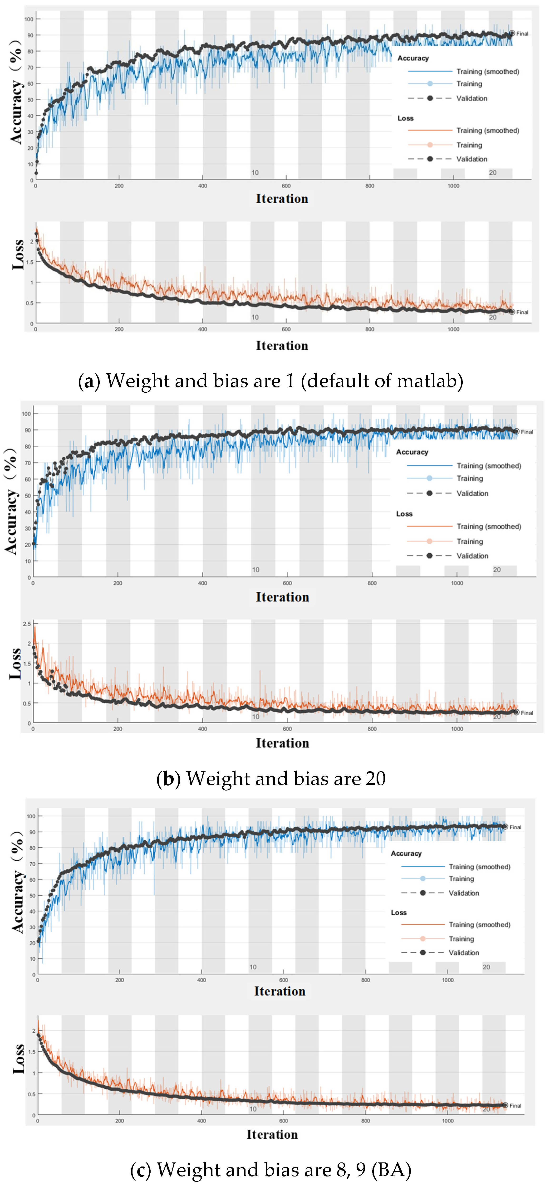
4.1. Neural Network Training

The transfer learning neural network can realize small samples and achieve high accuracy output with fewer iterations. The neural network is trained on the Matlab 2018(a) framework with dual 1080 ti GPUs and dual E5-2620 v4 dual-core CPUs with 64 GB of memory. The first 7 layers of the transfer Alexnet network are used, followed by a fully connected layer, a softmax layer, and a classification layer to construct a 10-layer deep convolutional neural network. The parameters of the fully connected layer weight and the bias learning rate factor in the newly added layer are set to 8 and 9, respectively, according to the results of the improved bat algorithm. Mini-batch gradient descent (MBGD) is used in the training process. The number of input pictures is 30 and the number of iterations is 1140. The neural network training process is shown in Figure 7.
Figure 7 shows the bat algorithm optimization learning rate factor, the default learning rate factor, and the artificially set learning rate factor optimization iterative process. The upper half of the graph is the accuracy curve, and the lower half is the loss function curve. The default learning rate factor of Matlab is 1, the manual setting is 20, and the learning rate factor is optimized to be 8,9. From the accuracy curve and the loss function convergence curve, the network training convergence with the default learning rate factor of 1 is significantly slower than the other two networks. It starts to converge in about 700 iterations, resulting in low computational efficiency and waste of computing resources. When the learning rate factor is 20, the network convergence starts to be flat at 400 times, and the bat algorithm optimization is about 500 times. From the final training accuracy curve, it can be seen that the accuracy of the default 1 and manual setting 20 is less than 90%. The accuracy of the bat algorithm optimization neural network is far more than 90%. In summary, although the convergence speed of bat algorithm is slightly slower than that of manual settings, the accuracy of bat algorithm is higher, and it avoids falling into local optimum in the process of network training.
For further comparison, HOG + SVM is used for comparison experiments. In this paper, HOG + SVM is used to train and test the dataset in Table 2. Table 5 lists the accuracy of various methods.
It can be seen from Table 5 that the highest accuracy is the neural network optimized by the bat algorithm, which can reach 94.84%. The HOG+SVM method has the lowest accuracy rate of only 75.11%. The manual setting and the default value are not much different and are all below 90%.

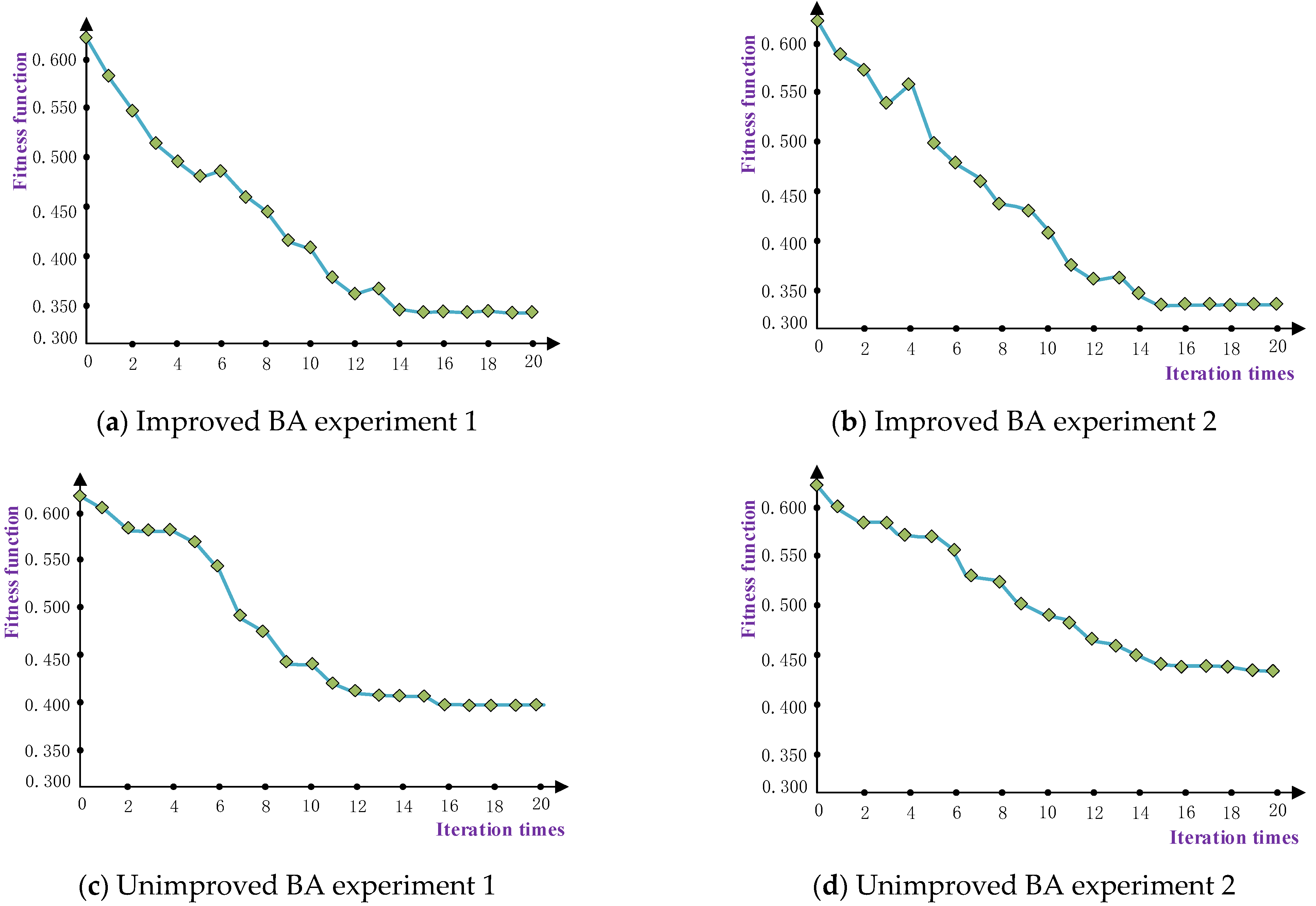
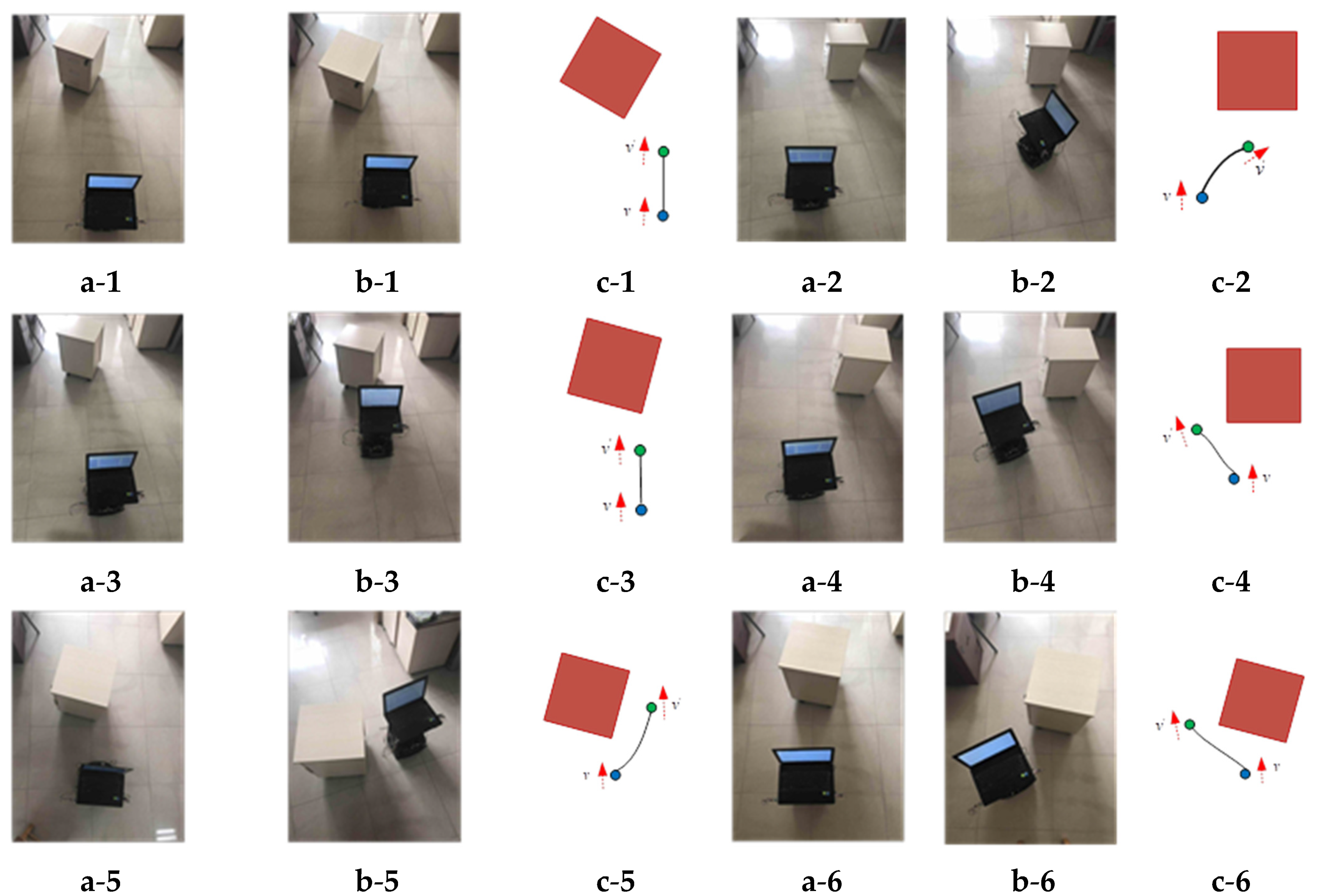
4.2. Experiments and Discussion

In order to verify the effectiveness of obstacle avoidance algorithm, this paper designs the experimental platform of wheeled robot as shown in Figure 8. The platform uses MATLAB to communicate with the motor drive board through serial port. Matlab sends the control instructions to two motor drive boards, and the motor drive board drives the DC motor to realize the obstacle bypass. In this paper, single frame evaluation and continuous obstacle avoidance evaluation are carried out. The improved bat optimized neural network trained by the workstation is transplanted to the notebook. The notebook is equipped with a single 2.40 GHz i7-4700mq CPU, no GPU, and 12 GB memory. The processing time of a frame of image by the neural network is about 60 ms.
In the experiment, the single frame image obtained by the wheeled robot is transported to the neural network for judgment. The detection environment is the environment where the training set is obtained. Figure 9 shows the output results of some single frame images by the neural network. The bottom of the picture is the label of the picture, and the green background above is the network output.
As shown in Figure 9, the neural network can extract the single frame image information obtained by the wheeled robot camera and output the near and far direction of the obstacles with an accuracy rate of 100%. In the case of good evaluation of a single frame image, continuous obstacle avoidance experiments are carried out in this paper. According to the distance and orientation of obstacles by the neural network, the motion rules are designed as shown in Table 6. In the process of wheeled robot rotation, the first rotation angle of wheeled robot is 60° and the forward speed is 0.5 m/s.
In this experiment, obstacles are located in different directions of wheeled robot. In order to verify the generalization of neural network, the detection environment is a new scene (not included in the training set). As shown in Figure 10, a is the state before obstacle avoidance, b is the state after obstacle avoidance, the blue point in c is the starting point, the green point in c is the ending point, the black curve in c represents the robot’s motion track, and the red block in c is the current obstacle.
In the continuous static obstacle avoidance experiment, six scenes are selected; the results are shown in Figure 10. In experiment 1, the obstacle is located far to the left of the wheeled robot, and the robot should walk straight. The path conforms to the obstacle avoidance rules. In experiment 2, the obstacle is located in the right far distance. According to the correct rules, the robot should go straight, but the robot turns right. Although there is no collision, it does not conform to the movement rules. Experiments 3, 4, 5, and 6 show that the obstacles are located in the middle and far, right near, left near and middle near, respectively. The robot successfully avoids the obstacles, enters the wide area, and obtains the wall crack image and the building damage information. Compared with laser ranging obstacle avoidance and ultrasonic ranging obstacle avoidance [21,22,23], the method proposed in this paper has the advantages of low sensor price and low cost of obstacle avoidance system. However, due to the limitation that the optical sensor needs to work in a bright environment, the method proposed in this paper can only work in an indoor environment with good lighting conditions. Through the acquired image information, the remote health monitoring of building can be realized. Figure 11 shows the schematic diagram of a ground robot equipped with a multispectral camera, and the detection of wall cracks is realized by carrying Rededge.

5. Conclusions

This paper proposes an optimized transfer-CNN method based on improved bat algorithm. The image of the front of the wheeled robot is input into the neural network through the camera, and the neural network outputs ‘Left Proximity’, ‘Left Far’, ‘Middle Proximity’, ‘Middle Far’, ‘Right Proximity’, and ‘Right Far’. For the problem that supervised learning needs a large amount of labeled data, automatic image classification and far and near framing are achieved by using camera stacking. The accuracy of the neural network test set by the improved bat algorithm reached 94.84%. In the six groups of continuous obstacle avoidance experiments, only one group violates the rules of obstacle avoidance, but there is no collision, so it can achieve better obstacle avoidance. Through the optimization transfer-CNN, the unmanned vehicle equipped with the visual crack detection camera is used to realize the automatic evaluation of the building structure safety. At this stage, the method proposed in this paper is only for static obstacles, but there are often dynamic obstacles such as moving humans in the indoor environment. Therefore, the perception and obstacle avoidance of dynamic obstacles is also the next research direction of indoor monocular ground vehicle.

Author Contributions

Conceptualization, S.W.; methodology, S.W.; software, S.W.; data curation, Y.C.; writing—original draft preparation, S.W.; writing—review and editing, S.W., P.Q. and W.Z.; visualization, L.W.; supervision, X.H.; project administration, L.W. and X.H.; funding acquisition, L.W. and X.H. All authors have read and agreed to the published version of the manuscript.

Funding

This research was funded by Youth Science Fund Project of National Natural Science Foundation of China, grant number 31801783; Professor workstation of intelligent plant protection machinery and precision pesticide application technology, grant number 202005511011020.

Institutional Review Board Statement

Not applicable.

Informed Consent Statement

Not applicable.

Data Availability Statement

Not applicable.

Acknowledgments

We would like to thank Jian Chen, Zichao Zhang, Xuzan Liu, Kai Zhang, Peng Qi, and Wei Zhang for their helpful work on their preliminary basic work.

Conflicts of Interest

The authors declare no conflict of interest.

References

  1. Szrek, J.; Zimroz, R.; Wodecki, J.; Michalak, A.; Góralczyk, M.; Worsa-Kozak, M. Application of the Infrared Thermography and Unmanned Ground Vehicle for Rescue Action Support in Underground Mine—The AMICOS Project. Remote Sens. 2020, 13, 69. [Google Scholar] [CrossRef]
  2. Liu, Q.; Li, Z.; Yuan, S.; Zhu, Y.; Li, X. Review on Vehicle Detection Technology for Unmanned Ground Vehicles. Sensors 2021, 21, 1354. [Google Scholar] [CrossRef] [PubMed]
  3. Castaman, N.; Tosello, E.; Antonello, M.; Bagarello, N.; Gandin, S.; Carraro, M.; Munaro, M.; Bortoletto, R.; Ghidoni, S.; Menegatti, E.; et al. RUR53: An unmanned ground vehicle for navigation, recognition, and manipulation. Adv. Robot. 2021, 35, 1–18. [Google Scholar] [CrossRef]
  4. Wang, S.; Zhang, Z.; Cao, Y.; Liu, X.; Zhang, K.; Chen, J. An Obstacle Avoidance Method for Indoor Flaw Detection Unmanned Robot Based on Transfer Neural Network. Earth Space 2021, 2021, 484–493. [Google Scholar]
  5. Rajashekaraiah, G.; Sevil, H.E.; Dogan, A. PTEM based moving obstacle detection and avoidance for an unmanned ground vehicle. In Proceedings of the Dynamic Systems and Control Conference. Am. Soc. Mech. Eng. 2017, 58288, V002T21A009. [Google Scholar]
  6. Yang, W.; Ankit, G.; Rahul, S.; Heydari, M.; Desai, A.; Yang, H. Obstacle Avoidance Strategy and Implementation for Unmanned Ground Vehicle Using LIDAR. SAE Int. J. Commer. Veh. 2017, 10, 50–56. [Google Scholar]
  7. Bhave, U.; Showalter, G.D.; Anderson, D.J.; Roucco, C.; Hensley, A.C.; Lewin, G.C. Automating the Operation of a 3D-Printed Unmanned Ground Vehicle in Indoor Environments. In Proceedings of the 2019 Systems and Information Engineering Design Symposium (SIEDS), Charlottesville, VA, USA, 26 April 2019; IEEE: Piscataway, NJ, USA, 2019; pp. 1–6. [Google Scholar]
  8. Khan, M.; Hassan, S.; Ahmed, S.I.; Iqbal, J. Stereovision-based real-time obstacle detection scheme for unmanned ground vehicle with steering wheel drive mechanism. In Proceedings of the 2017 International Conference on Communication, Computing and Digital Systems (C-CODE), Islamabad, Pakistan, 8–9 March 2017; IEEE: Piscataway, NJ, USA, 2017; pp. 380–385. [Google Scholar]
  9. Levkovits-Scherer, D.S.; Cruz-Vega, I.; Martinez-Carranza, J. Real-time monocular vision-based UAV obstacle detection and collision avoidance in GPS-denied outdoor environments using CNN MobileNet-SSD. In Proceedings of the Mexican International Conference on Artificial Intelligence, Xalapa, Mexico, 27 October–2 November 2019; Springer: Cham, Switzerland, 2019; pp. 613–621. [Google Scholar]
  10. Yu, H.; Zhang, F.; Huang, P.; Wang, C.; Yuanhao, L. Autonomous Obstacle Avoidance for UAV based on Fusion of Radar and Monocular Camera. In Proceedings of the 2020 IEEE/RSJ International Conference on Intelligent Robots and Systems (IROS), Las Vegas, NV, USA, 24 October–24 January 2021; IEEE: Piscataway, NJ, USA, 2020; pp. 5954–5961. [Google Scholar]
  11. Eppenberger, T.; Cesari, G.; Dymczyk, M.; Siegwart, R.; Dube, R. Leveraging stereo-camera data for real-time dynamic obstacle detection and tracking. In Proceedings of the 2020 IEEE/RSJ International Conference on Intelligent Robots and Systems (IROS), Las Vegas, NV, USA, 24 October–24 January 2021; IEEE: Piscataway, NJ, USA, 2020; pp. 10528–10535. [Google Scholar]
  12. Lv, J.; Qu, C.; Du, S.; Zhao, X.; Yin, P.; Zhao, N.; Qu, S. Research on obstacle avoidance algorithm for unmanned ground vehicle based on multi-sensor information fusion. Math. Biosci. Eng. MBE 2021, 18, 1022–1039. [Google Scholar] [CrossRef] [PubMed]
  13. Hu, C.; Zhao, L.; Cao, L.; Tjan, P.; Wang, N. Steering control based on model predictive control for obstacle avoidance of unmanned ground vehicle. Meas. Control 2020, 53, 501–518. [Google Scholar] [CrossRef] [Green Version]
  14. Mohamed, A.; Ren, J.; Sharaf, A.M.; EI-Gindy, M. Optimal path planning for unmanned ground vehicles using potential field method and optimal control method. Int. J. Veh. Perform. 2018, 4, 1–14. [Google Scholar] [CrossRef]
  15. Chen, Y.; Bai, G.; Zhan, Y.; Hu, X.; Liu, J. Path Planning and Obstacle Avoiding of the USV Based on Improved ACO-APF Hybrid Algorithm with Adaptive Early-Warning. IEEE Access 2021, 9, 40728–40742. [Google Scholar] [CrossRef]
  16. Singla, A.; Padakandla, S.; Bhatnagar, S. Memory-Based Deep Reinforcement Learning for Obstacle Avoidance in UAV with Limited Environment Knowledge. IEEE Trans. Intell. Transp. Syst. 2021, 22, 107–118. [Google Scholar] [CrossRef]
  17. Wang, S.; Han, Y.; Chen, J.; Pan, Y.; Cao, Y.; Meng, H. A transfer-learning-based feature classification algorithm for UAV imagery in crop risk management. Desalination Water Treat. 2020, 181, 330–337. [Google Scholar] [CrossRef]
  18. Papakonstantinou, A.; Batsaris, M.; Spondylidis, S.; Topouzelis, K. A Citizen Science Unmanned Aerial System Data Acquisition Protocol and Deep Learning Techniques for the Automatic Detection and Mapping of Marine Litter Concentrations in the Coastal Zone. Drones 2021, 5, 6. [Google Scholar] [CrossRef]
  19. Meena, S.D.; Agilandeeswari, L. Smart Animal Detection and Counting Framework for Monitoring Livestock in an Autonomous Unmanned Ground Vehicle Using Restricted Supervised Learning and Image Fusion. Neural Process. Lett. 2021, 53, 1253–1285. [Google Scholar] [CrossRef]
  20. Yang, X.S. A New Metaheuristic Bat-Inspired Algorithm. Comput. Knowl. Technol. 2010, 284, 65–74. [Google Scholar]
  21. Trieu, H.T.; Nguyen, H.T.; Willey, K. Shared control strategies for obstacle avoidance tasks in an intelligent wheelchair. In Proceedings of the 2008 30th Annual International Conference of the IEEE Engineering in Medicine and Biology Society, Vancouver, BC, Canada, 20–24 August 2008; IEEE: Piscataway, NJ, USA, 2008; pp. 4254–4257. [Google Scholar]
  22. Wang, C.; Savkin, A.V.; Clout, R.; Nguyen, H.T. An intelligent robotic hospital bed for safe transportation of critical neurosurgery patients along crowded hospital corridors. IEEE Trans. Neural Syst. Rehabil. Eng. 2014, 23, 744–754. [Google Scholar] [CrossRef] [PubMed]
  23. Ruíz-Serrano, A.; Reyes-Fernández, M.C.; Posada-Gómez, R.; Martínez-Sibaja, A.; Aguilar-Lasserre, A.A. Obstacle avoidance embedded system for a smart wheelchair with a multimodal navigation interface. In Proceedings of the 2014 11th International Conference on Electrical Engineering, Computing Science and Automatic Control (CCE), Ciudad del Carmen, Mexico, 29 September–3 October 2014; IEEE: Piscataway, NJ, USA, 2014; pp. 1–6. [Google Scholar]
Figure 1. Schematic diagram of working scene and problems of wheeled robot.
Drones 05 00105 g001
Figure 2. Wheeled robot video acquisition.
Drones 05 00105 g002
Figure 3. Pictures of each category.
Drones 05 00105 g003
Figure 4. An iterative process for bats looking for food.
Drones 05 00105 g004
Figure 5. BA iterative process.
Drones 05 00105 g005
Figure 6. BA optimization process.
Drones 05 00105 g006
Figure 7. Training process of neural networks.
Drones 05 00105 g007
Figure 8. Experiment platform.
Drones 05 00105 g008
Figure 9. The results of single frame.
Drones 05 00105 g009
Figure 10. The results of continuous obstacle avoidance.
Drones 05 00105 g010
Figure 11. The Monitoring of wall cracks.
Drones 05 00105 g011
Table 1. Camera parameter.
ModelPixelResolution
AONI-ANC1.3 million640 × 480
Table 2. Data set and label.
SubjectLeft ProximityLeft FarMiddle ProximityMiddle FarRight ProximityRight Far
Train313418166561369407
Test6383331127481
Lable100000010000001000000100000010000001
Table 3. BA parameters setting.
Subject m a x i t e r m f min f max   r i 0   A max  
Parameter2030−110.850.1
Table 4. Optimization results of improved BA.
SubjectImproved BA Algorithm
WeightlearnRateFactorBiasLearnratefacto
Experiment 110.23547.6387
Experiment 26.33349.4124
Average89
Table 5. Optimization results.
SubjectDefaultManual SettingBAHOG+SVM
Accuracy88.12%89.01%94.84%75.11%
Table 6. The design of movement rules.
The Output of Neural NetworkRight ProximityLeft ProximityMiddle ProximityRight FarLeft FarMiddle Far
Movement rulesTurn leftTurn rightTurn leftGo straightGo straightGo straight
Publisher’s Note: MDPI stays neutral with regard to jurisdictional claims in published maps and institutional affiliations.

