
Precision Landing for Low-Maintenance Remote Operations with UAVs

 , , ,
, , ,  , , and
Abstract
:1. Introduction
1.1. UAV Monitoring Platforms
1.2. Algorithms for UAV Precision Landing
1.3. Proposed Work
2. Materials and Methods
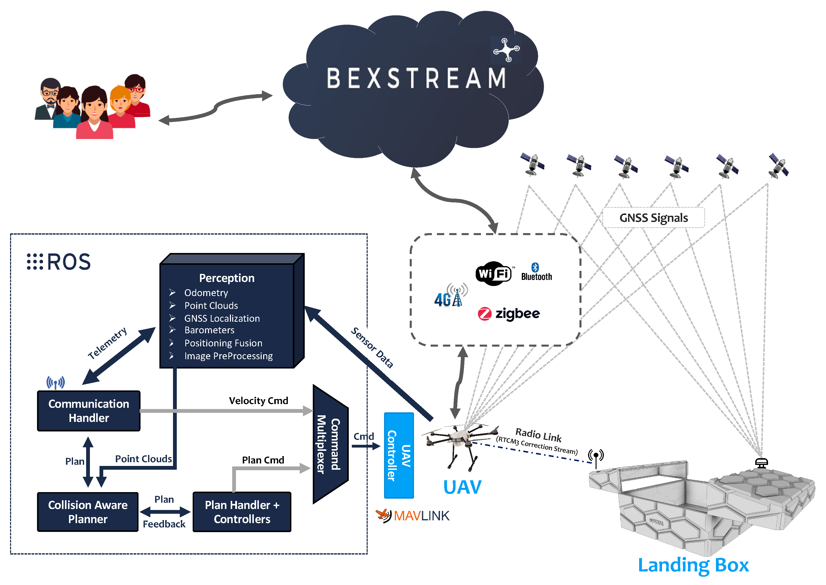
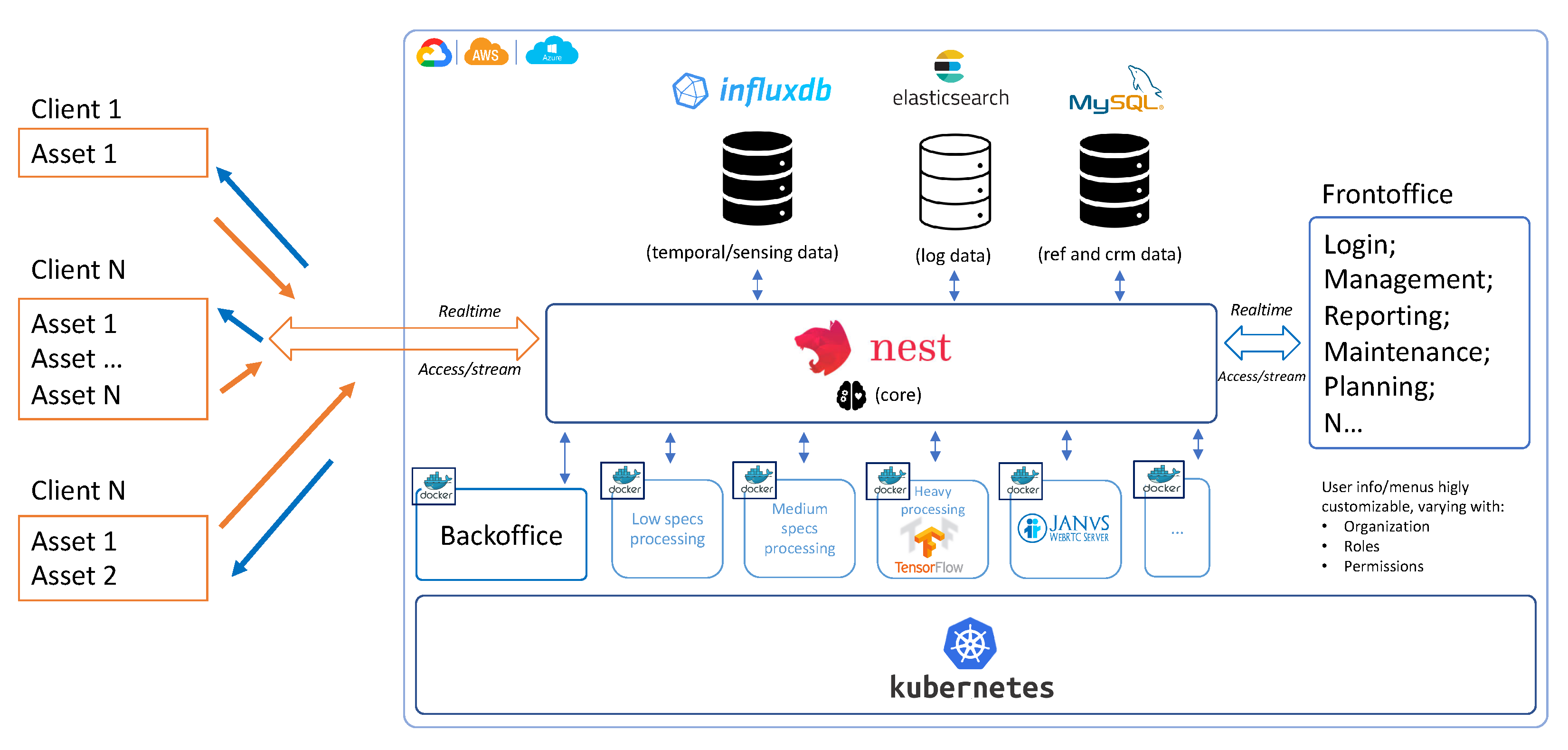
2.1. Architecture
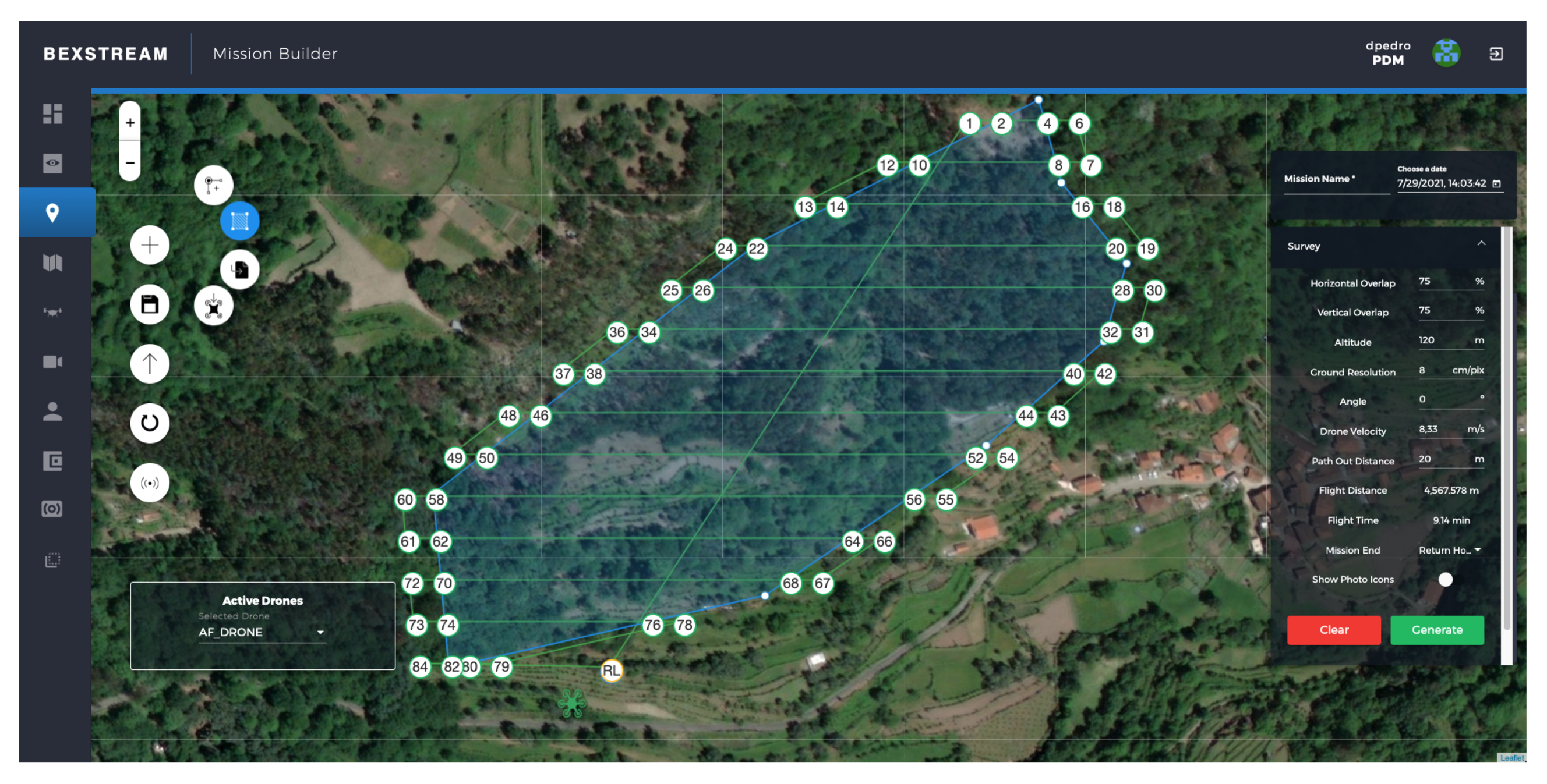
2.2. beXStream Platform
2.2.1. Backend
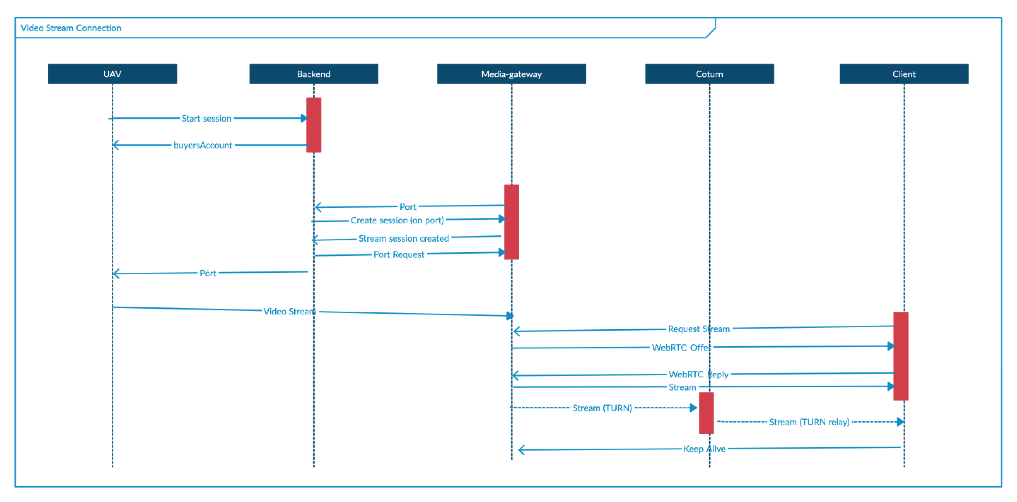
2.2.2. Media Gateway
2.2.3. Frontend
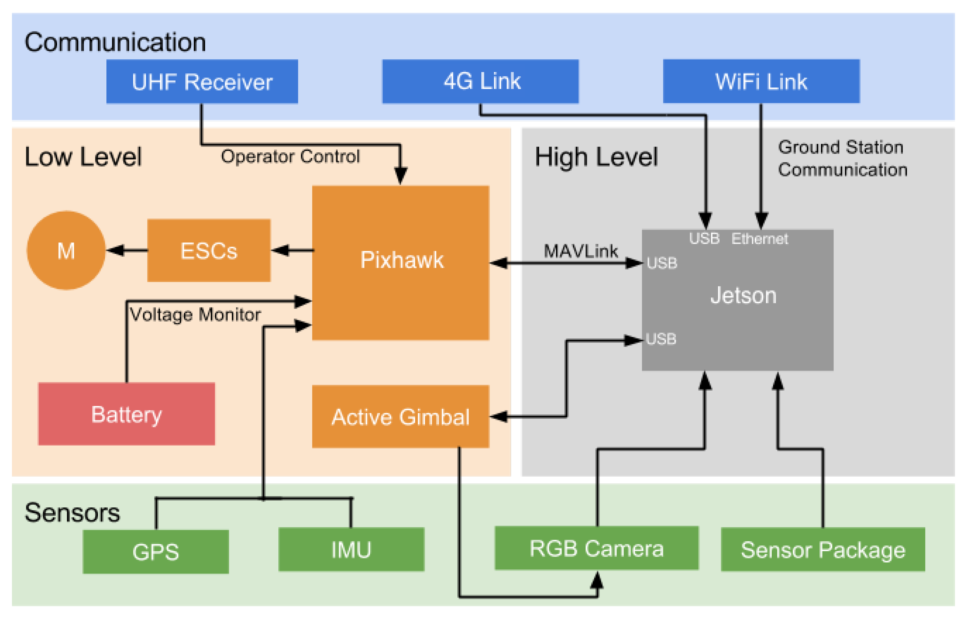
2.3. HEIFU UAV
- Cube Orange autopilot (running Ardupilot): used to control low-level operation and is responsible for ensuring a stable flight throughout the whole mission, following the pre-defined path from takeoff to landing. This hardware contains an Inertial Measurement Unit (IMU) and features a GNSS connection to provide the UAV’s position and orientation. Furthermore, the Cube connects to the Jetson Nano embedded system via a MAVlink protocol; through the Ultra High Frequency (UHF) receiver, HEIFU can be piloted by a Radio Frequency (RF) controller.
- RTK Positioning: based on a u-blox ZED F9P RTK [75] receiver, it can achieve much better accuracy than conventional positioning since it counts on a base station capable of delivering RTK differential correction information. For this purpose, the RTK base station can be either a portable solution, like the beRTK [76] or simply using the ALPHA Landing Base, providing a control accuracy in the range of 10 cm. The positioning accuracy is paramount in core applications of the HEIFU portfolio (like precision farming [77]).
- Jetson Nano: used to control the high-level operation. It receives data from the distance sensor (depth cameras), the Red Green Blue (RGB) camera, and communicates with external devices via a WiFi link.
- WiFi/Mobile Network Communications: the HEIFU counts on a native 4G modem. If available, WiFi communications can also be used. HEIFU also features Bluetooth and is prepared to carry a 5G modem to benefit from the higher bandwidth.
- An RGB camera on a gimbal stabilizer.
2.4. ALPHA Landing Base
- Solar Panels and respective Maximum Power Point Tracker (MPPT) for battery charging and self-powering;
- Power-grid connection;
- Smart Charging System, which decides which power source to use and if the internal batteries require charging;
- Internet connection (via WiFi or ethernet);
- Weather Station: to estimate the wind speed and detect the precipitation levels;
- Weight scale on the landing area. It helps the user quickly estimate the UAV payload and allows the landing area to detect if the drone has landed and estimated the maximum mission time for a specific payload and battery status;
- GNSS positioning and RTK Corrections;
- Landing Base with multiple trackable patterns;
- Mission scheduling.
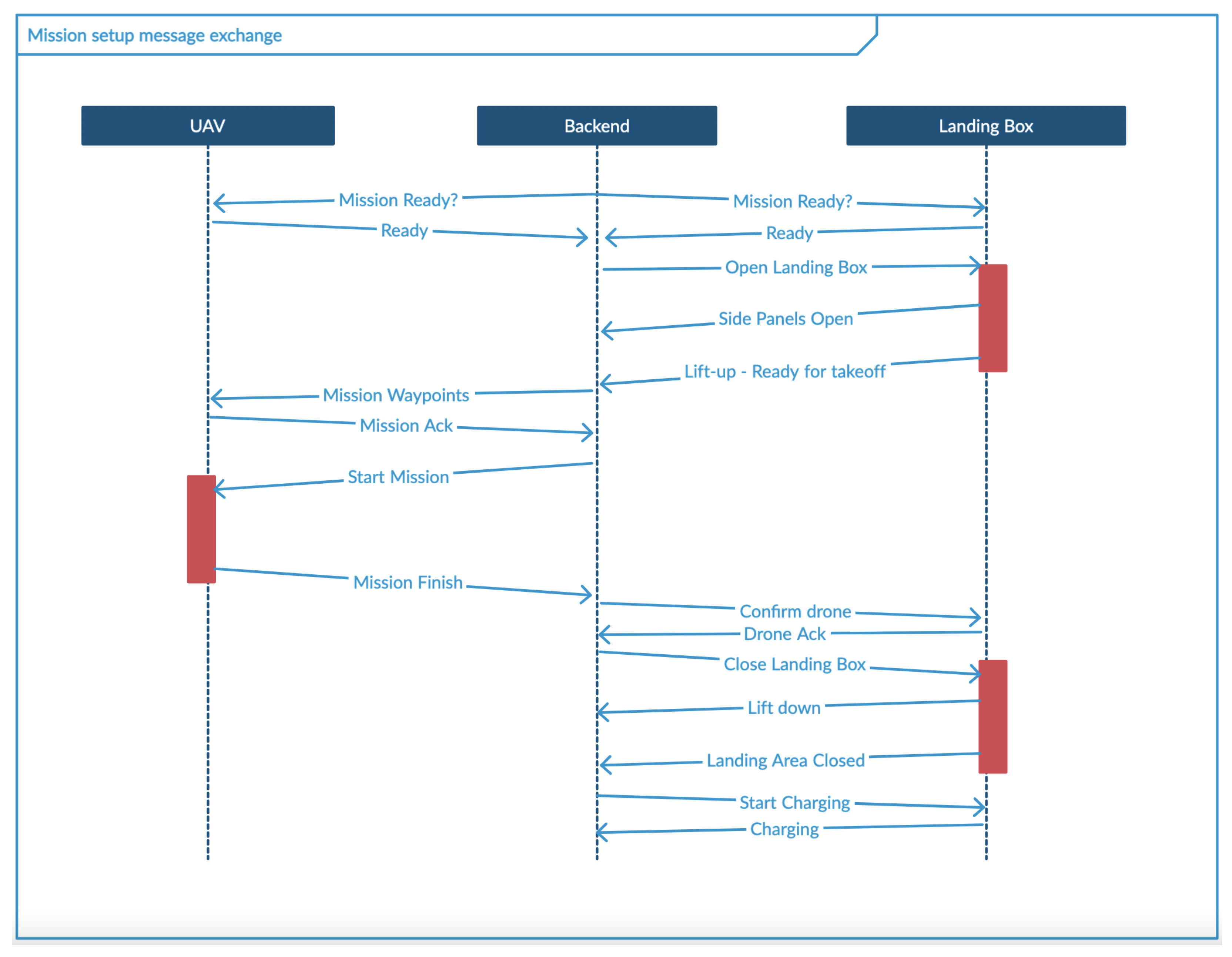
- An availability check for the landing area and UAV to perform a mission. On this point, the UAV should check if it has enough battery (defined by a battery charge threshold), and the landing area should check the weather conditions.
- Open the landing area. This is done in two steps:
- Open side panels.
- Lift the ground platform.
- Send a mission to UAV.
- Perform mission.
- Landing procedure.
- Confirm UAV successful landing.
- Close the landing area. This is done in two steps:
- (a)
- Lower the ground platform.
- (b)
- Close side panels.
- Start charging UAV’s batteries.
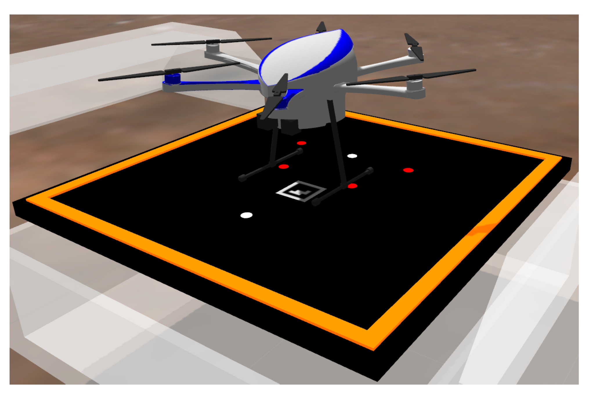
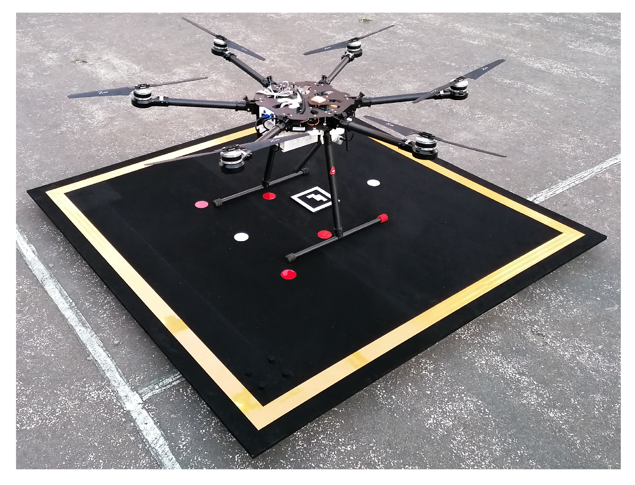
2.5. Computer Vision Positioning System
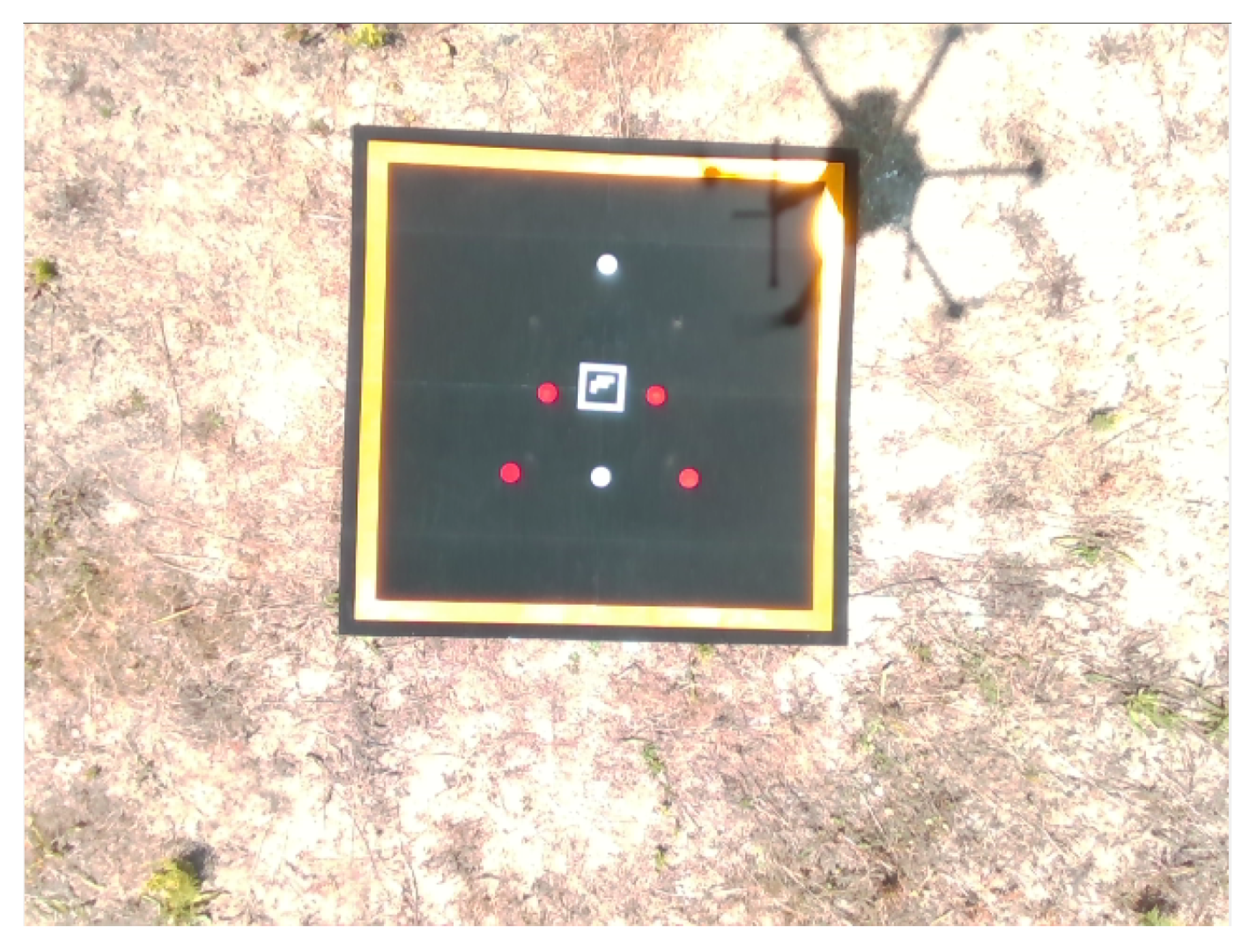
- A visual pattern created using reflective material drawn on the landing pad surface;
- A bottom facing camera on UAV capturing images at 30 Frames Per Second (FPS).
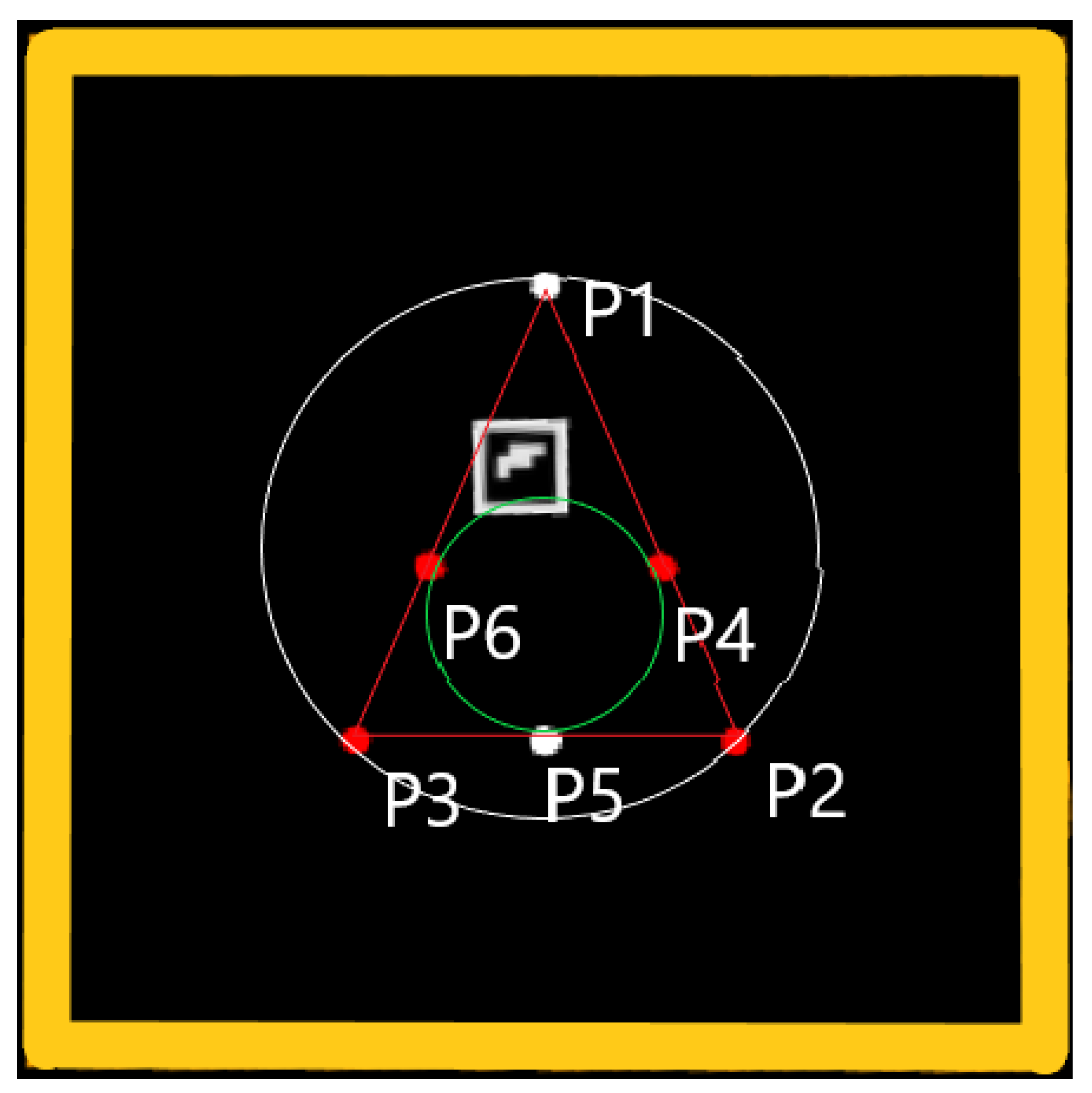
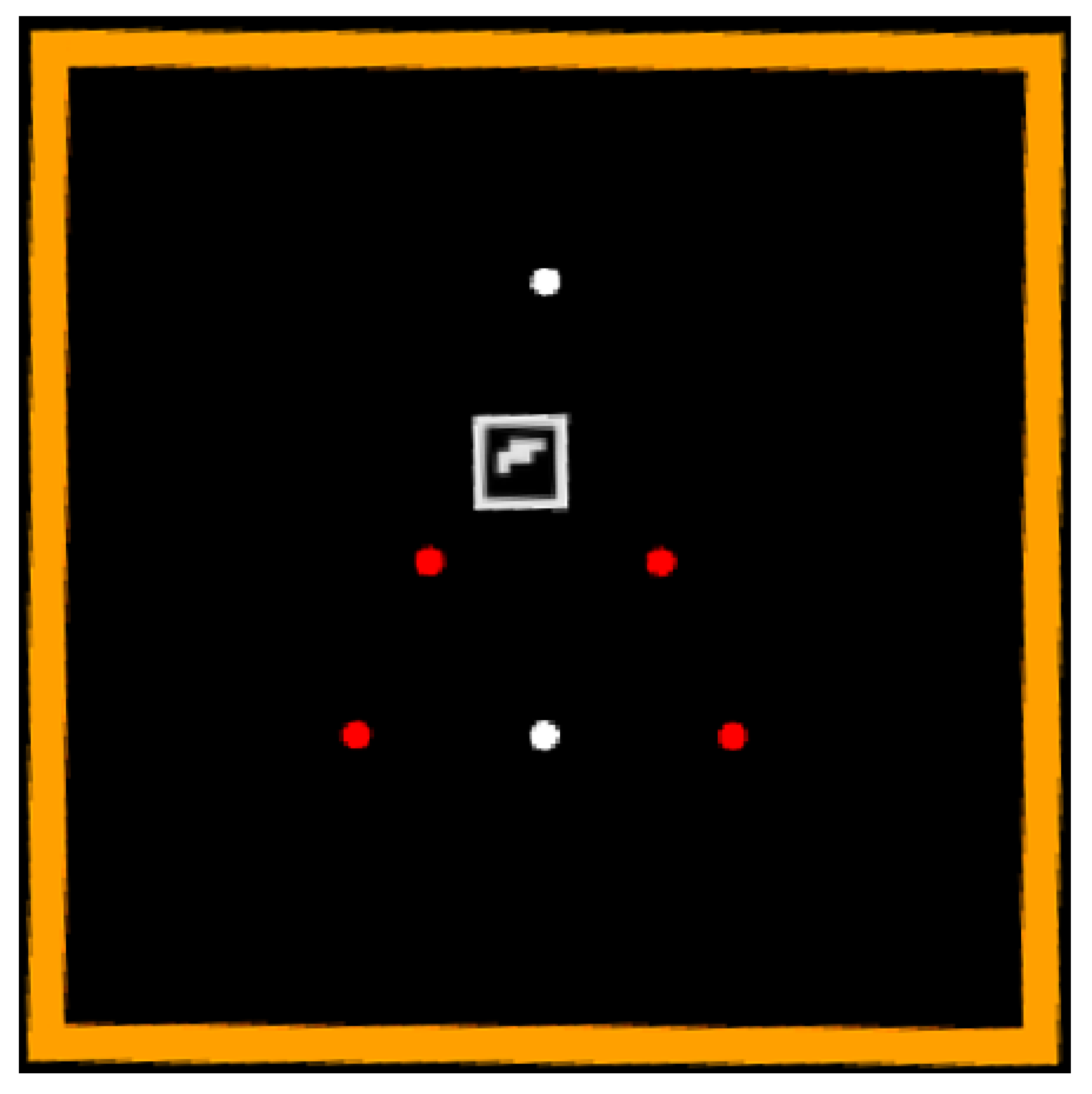
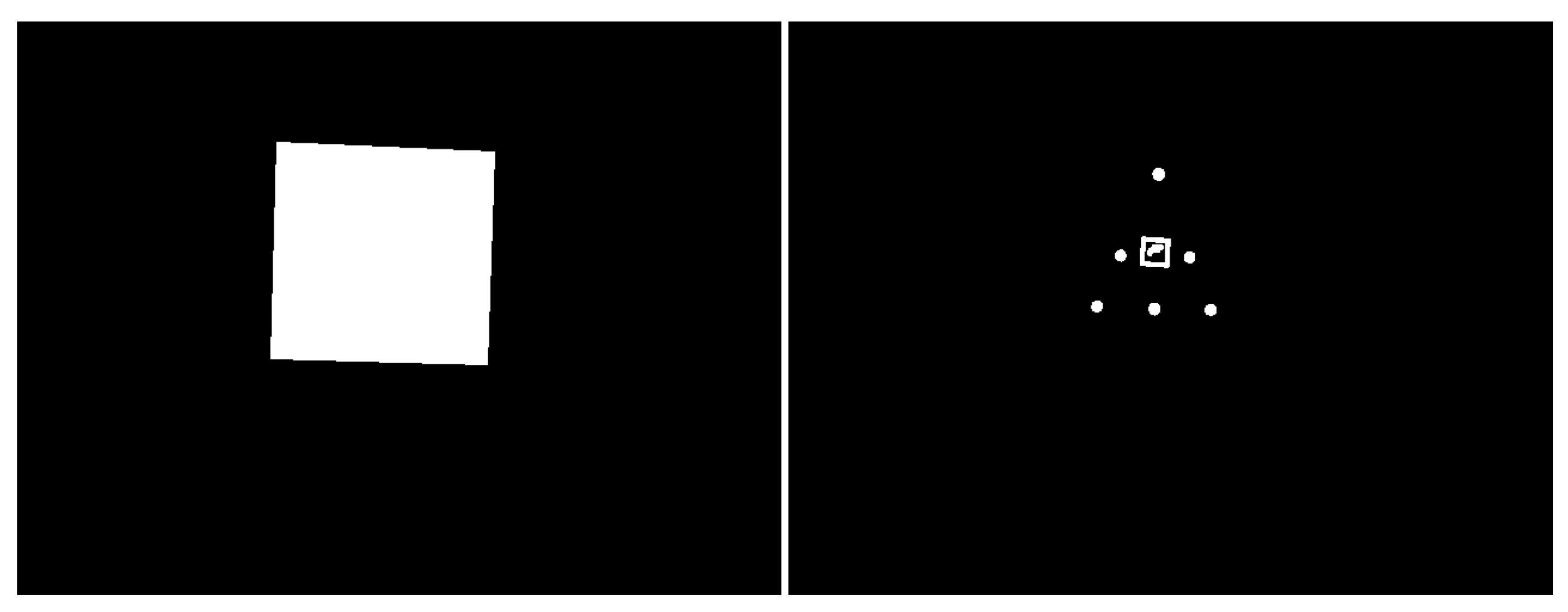
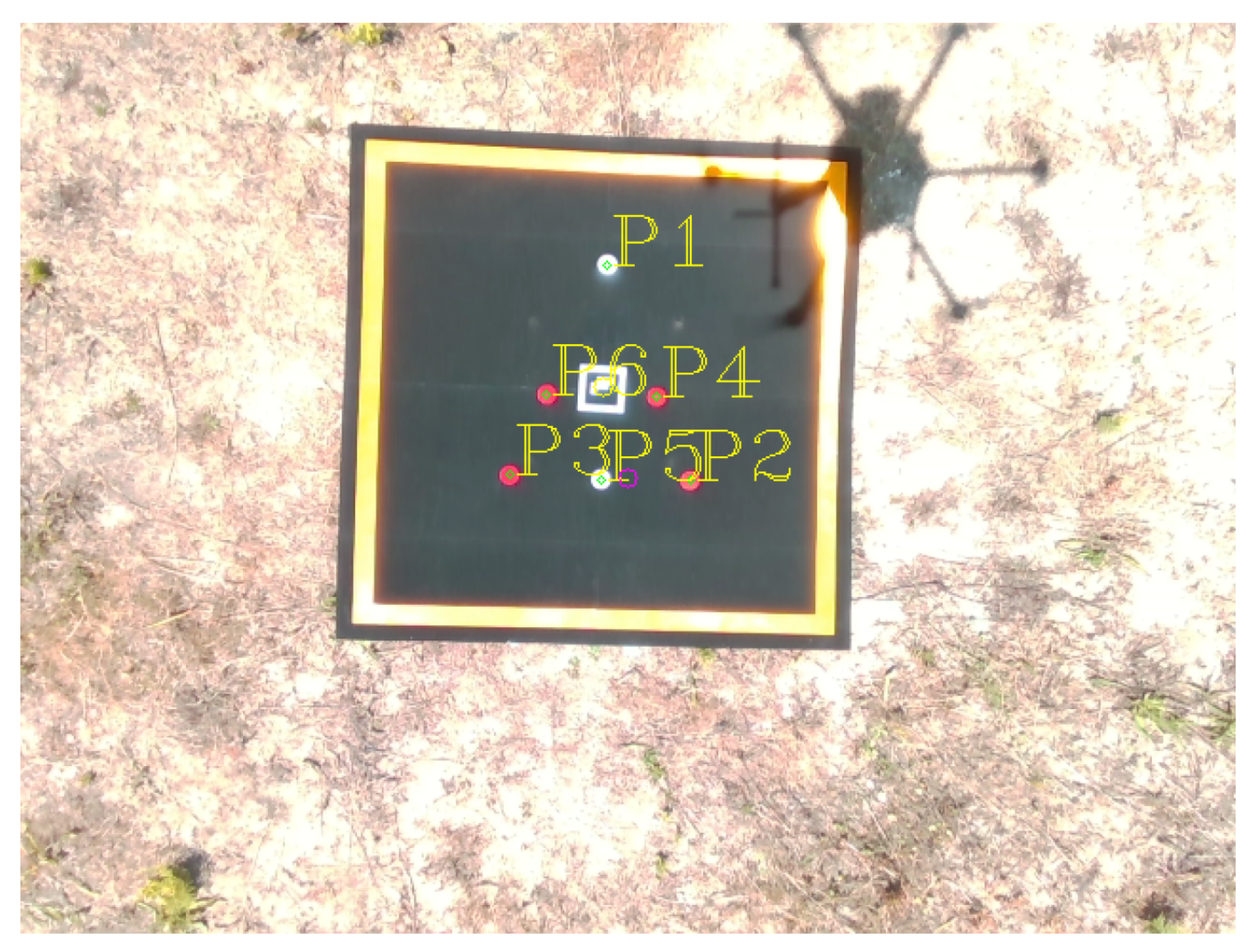
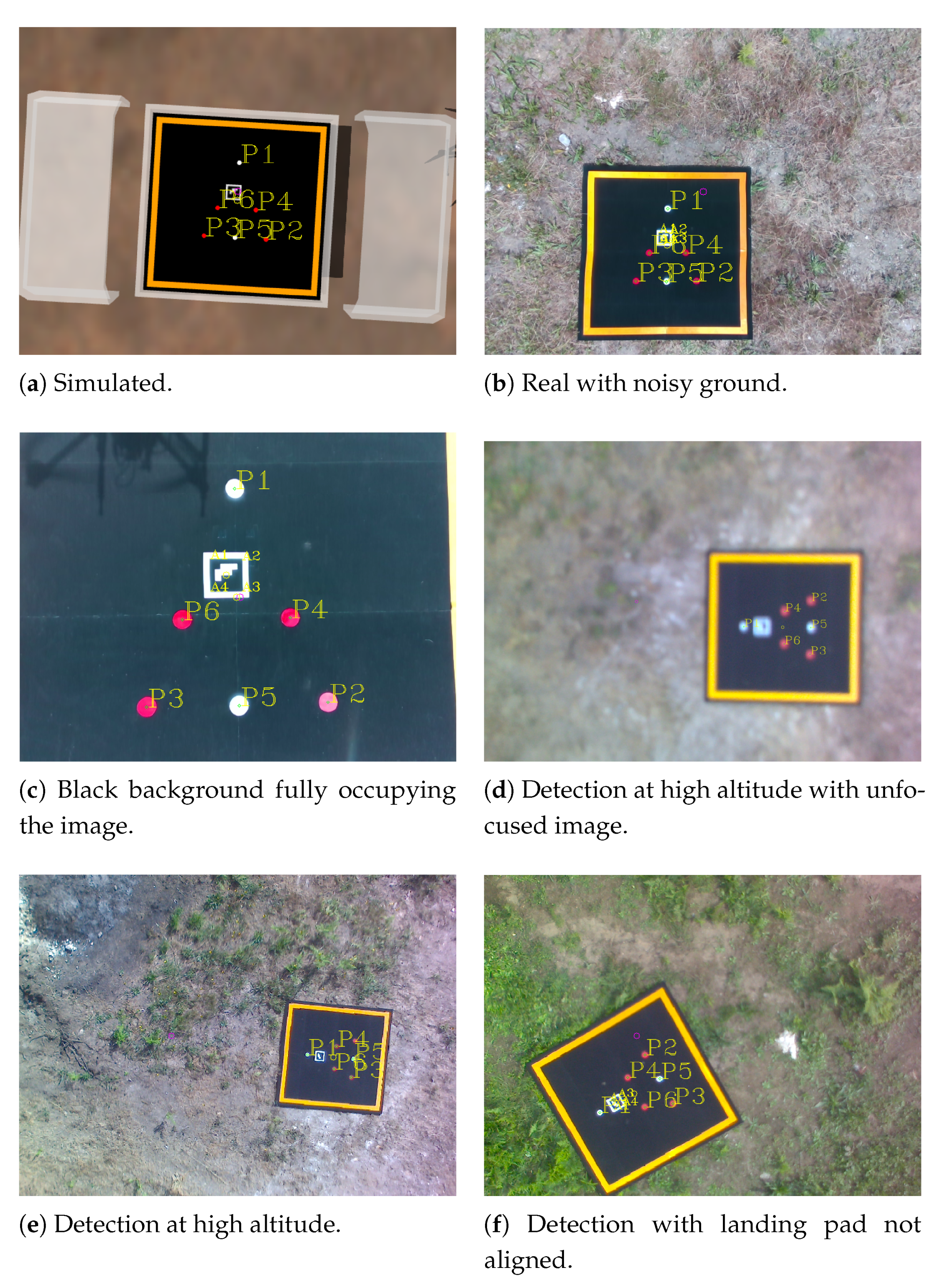
2.5.1. Visual Marker Description
- Masking frame—Its primary purpose is to mask the image by using only the area of the image where the marker is, reducing false positives and processing time.
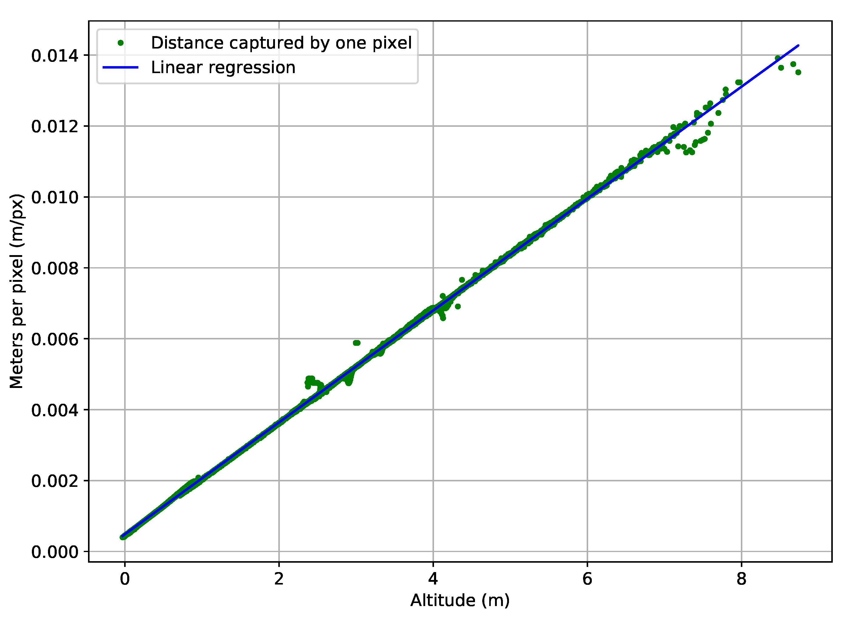
- Custom pattern defined by six points—The marker has a dimension that allows detection during the first step of the landing maneuver, even when the UAV is at an altitude of 5 m.
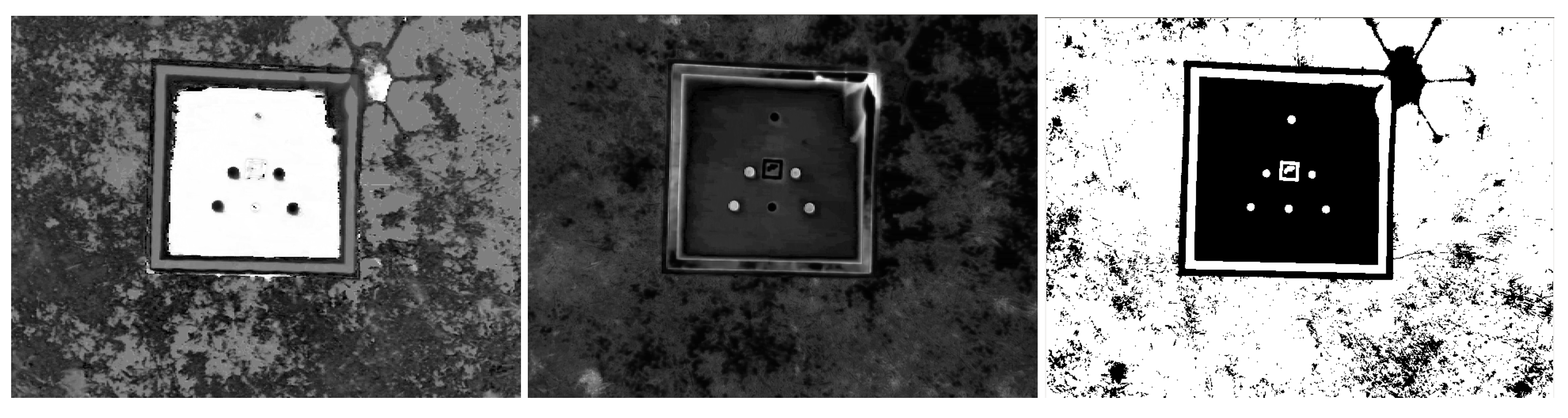
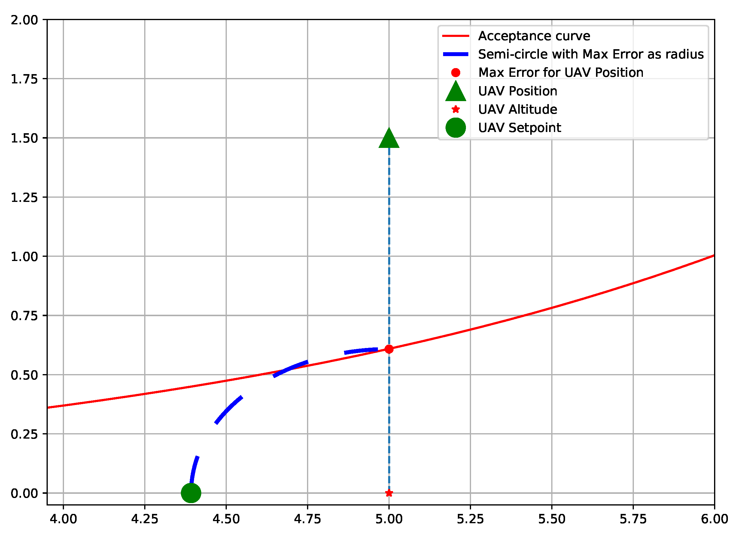
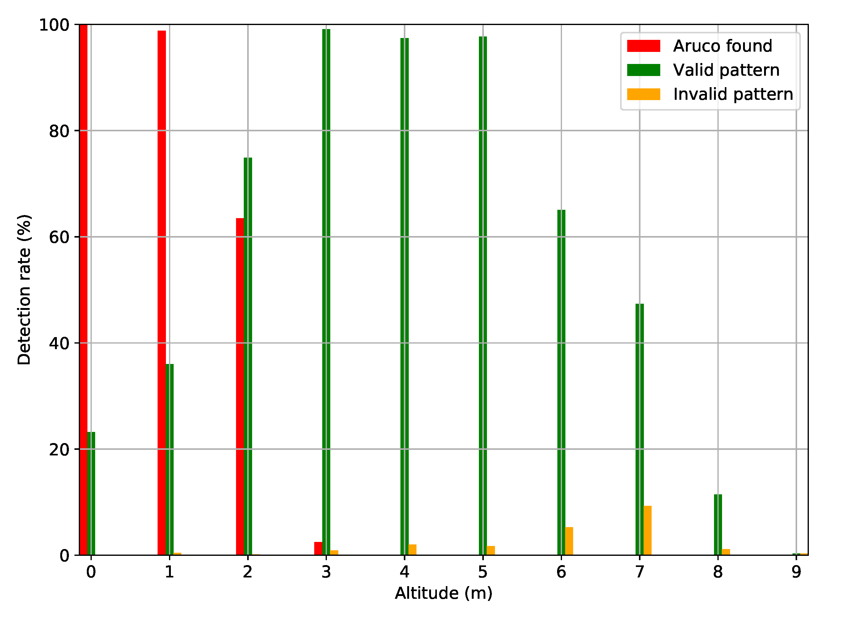
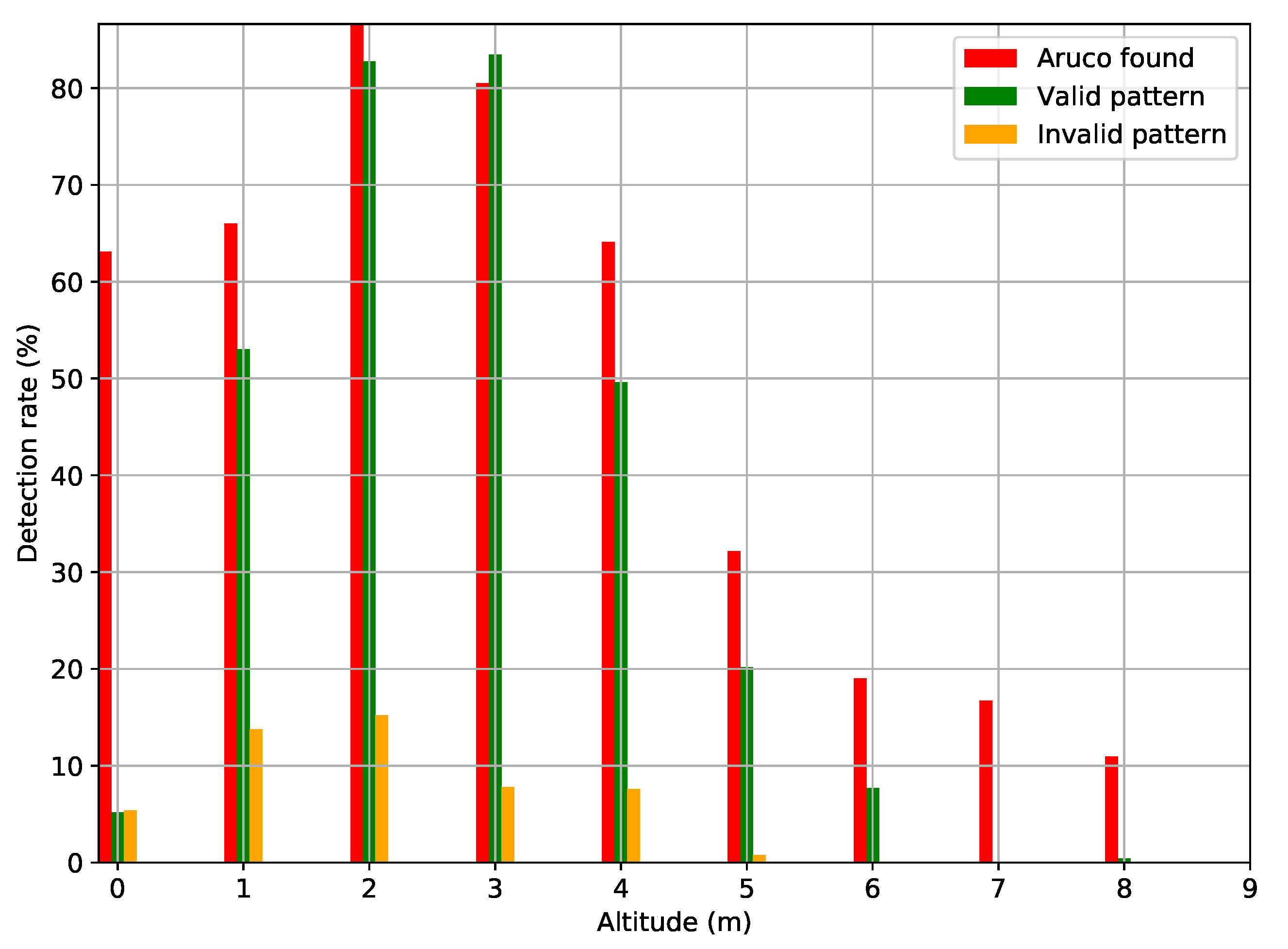
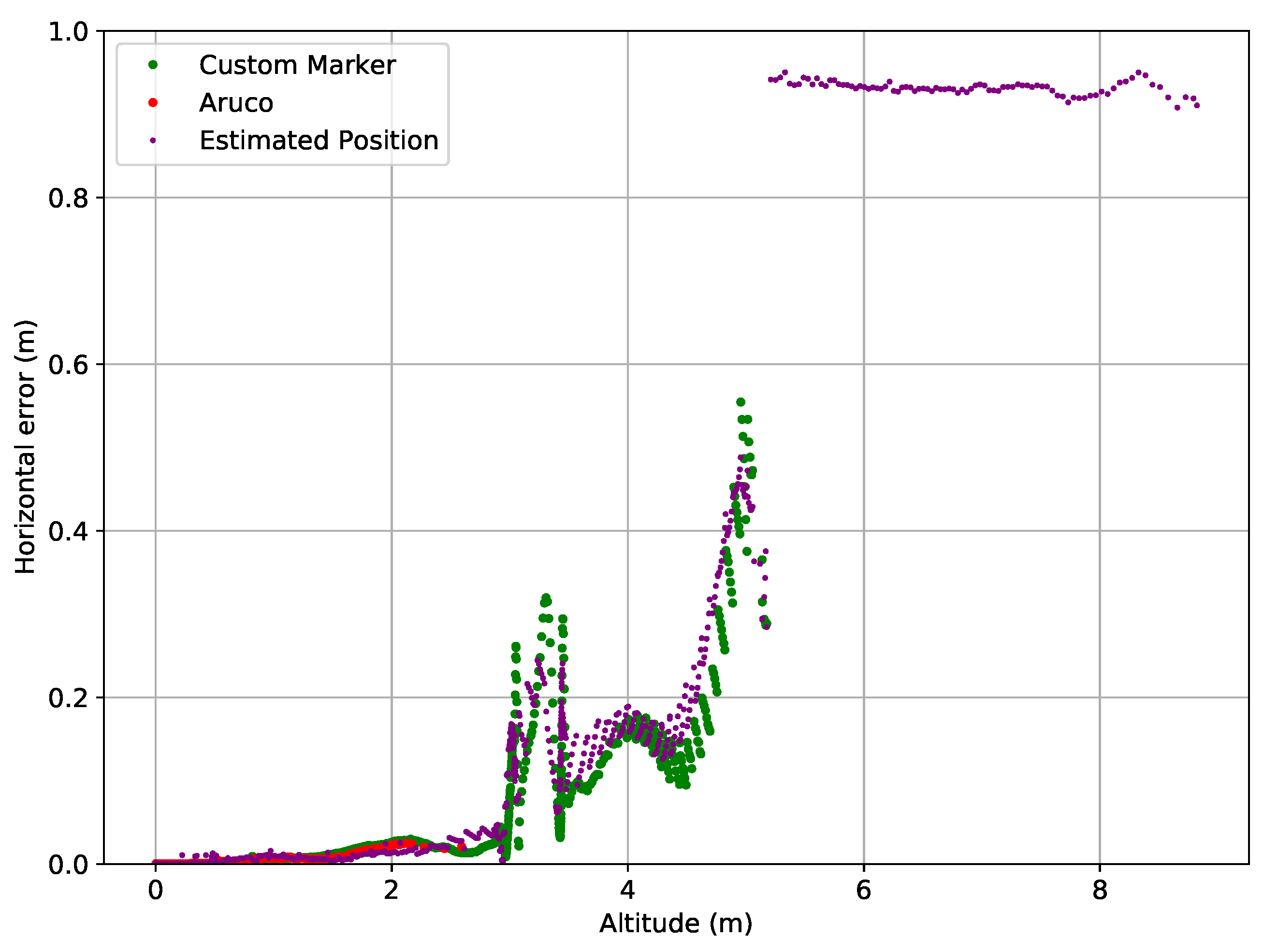
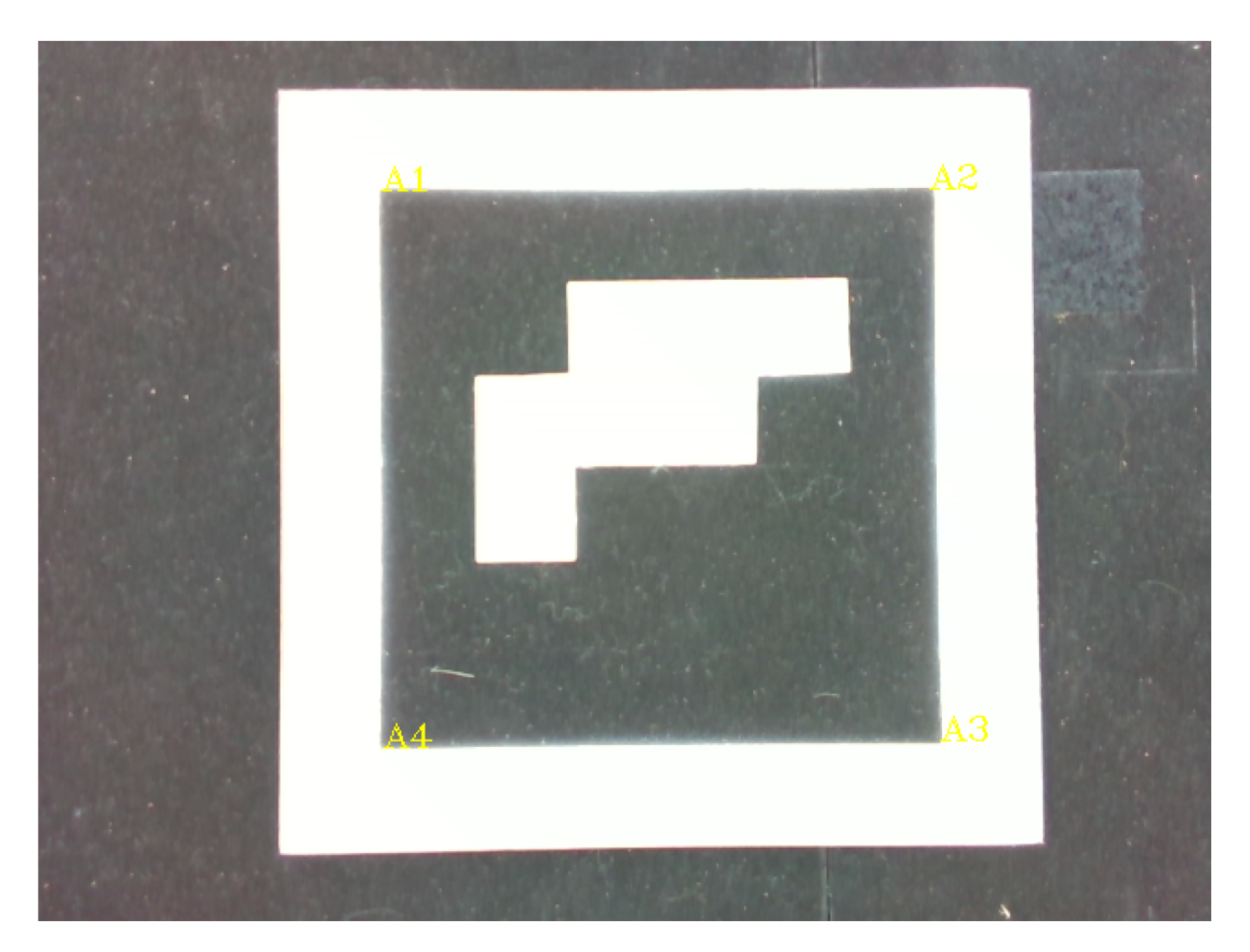
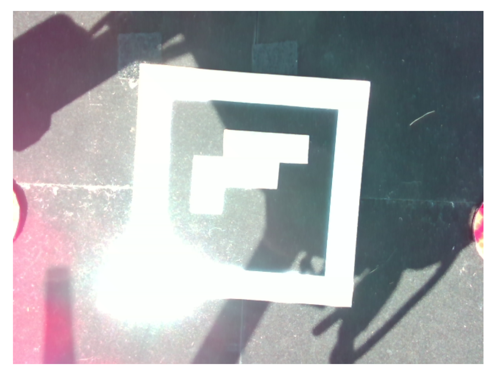
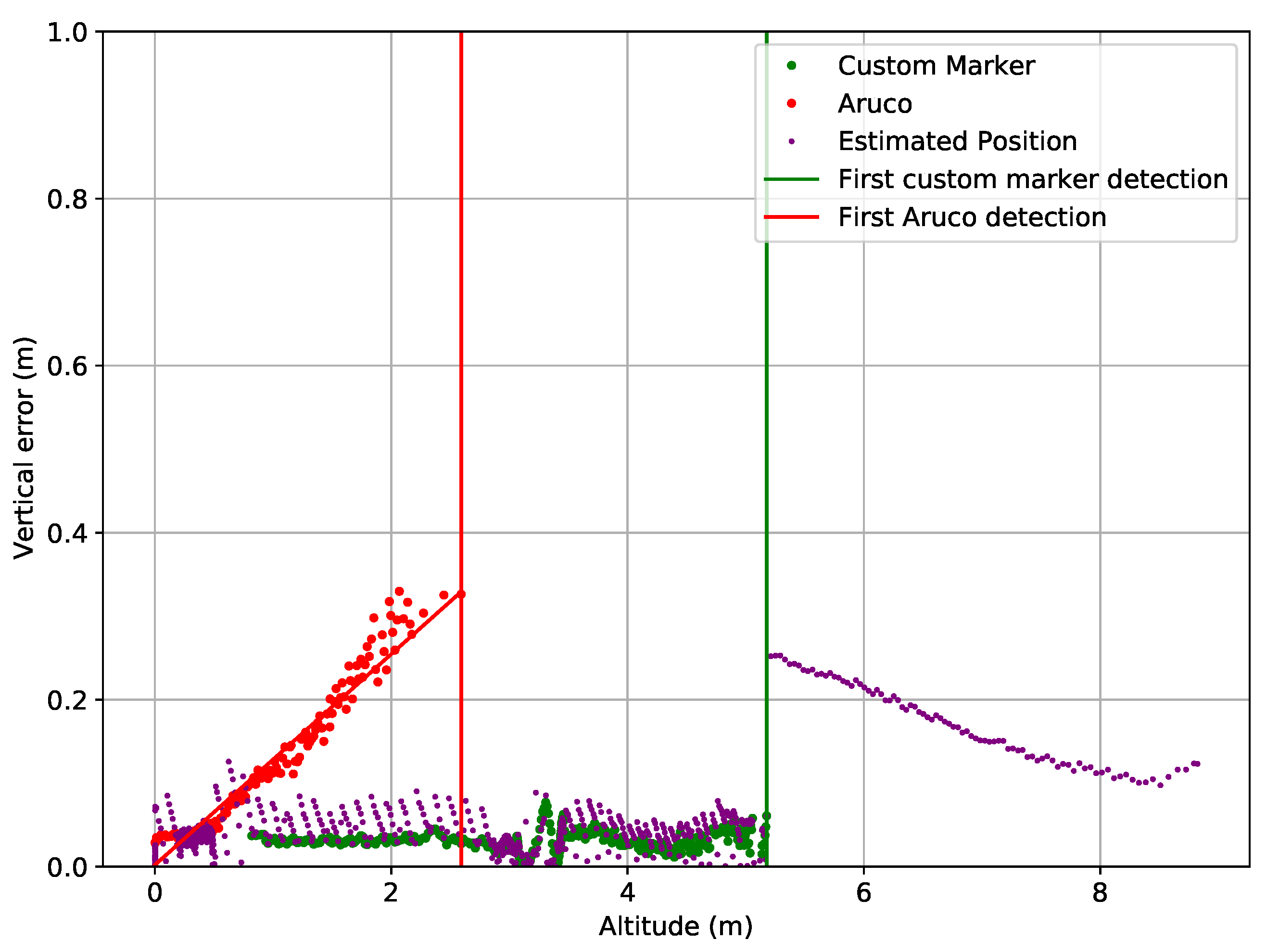
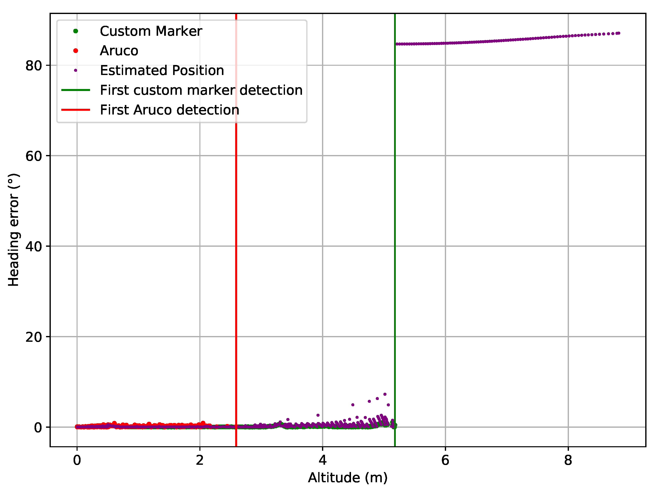
- Initially, at an altitude of approximately five meters, the masking frame and the custom pattern are the only detected elements due to the altitude. Additionally, since the Aruco is not a circle, it is rejected by the custom pattern algorithm.
- At mid-distance (less than two meters), the masking frame is not seen, but since the pattern has a black background, the pattern occupies all the image, so there is no need for it. At this distance, the Aruco can be detected alongside the custom pattern, both providing position through vision.
- In a final phase, at an altitude smaller than 50 cm, only the Aruco is seen on the image until the end of the maneuver, when the UAV finally lands.
- P1, P2, and P3 are the vertices of the triangle that is inside of a circle centered on the middle of the landing pad;
- P4, P5, and P6 are the points where a circle intersects the previous triangle.
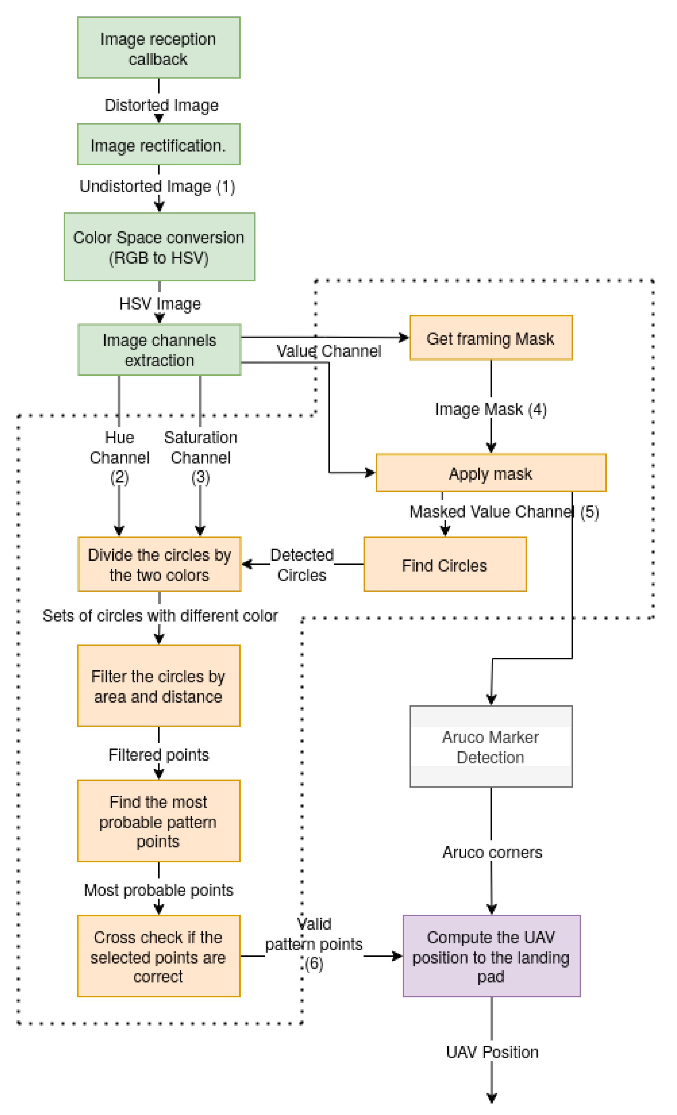
2.5.2. Image Processing
- Image preparation at green—the lens distortion is removed to assess the angular and linear relations of the pattern points. The image is converted to the Hue Saturation Value (HSV) colorspace for more invariance to color thresholding;
- Area of interest detection and custom pattern identification in yellow;
- Aruco marker detection in gray;
- UAV pose computation using the pattern position on the image plane.
2.6. Control and Trajectory
3. Application Environments
3.1. Simulation
3.2. Real World
4. Results
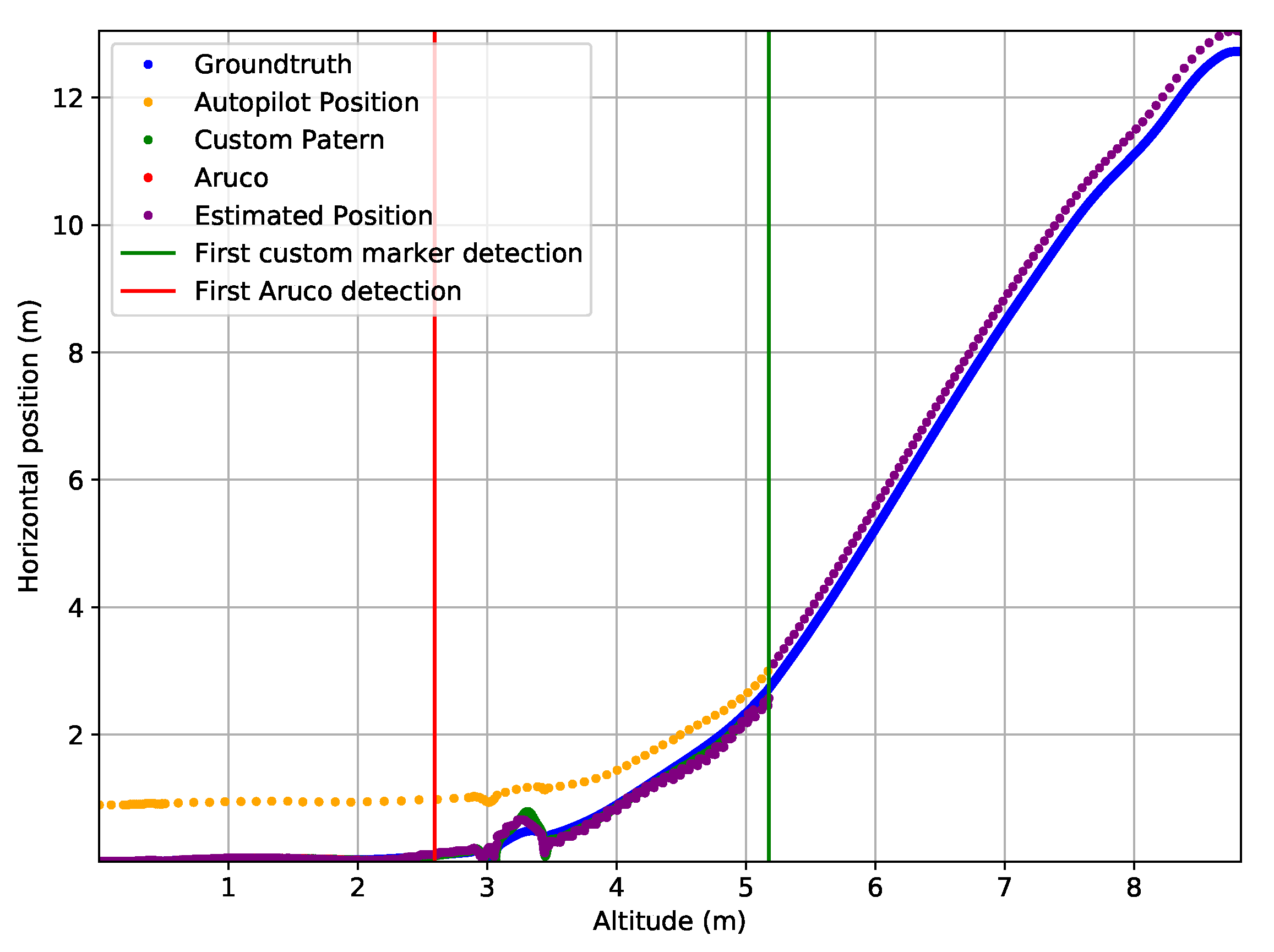
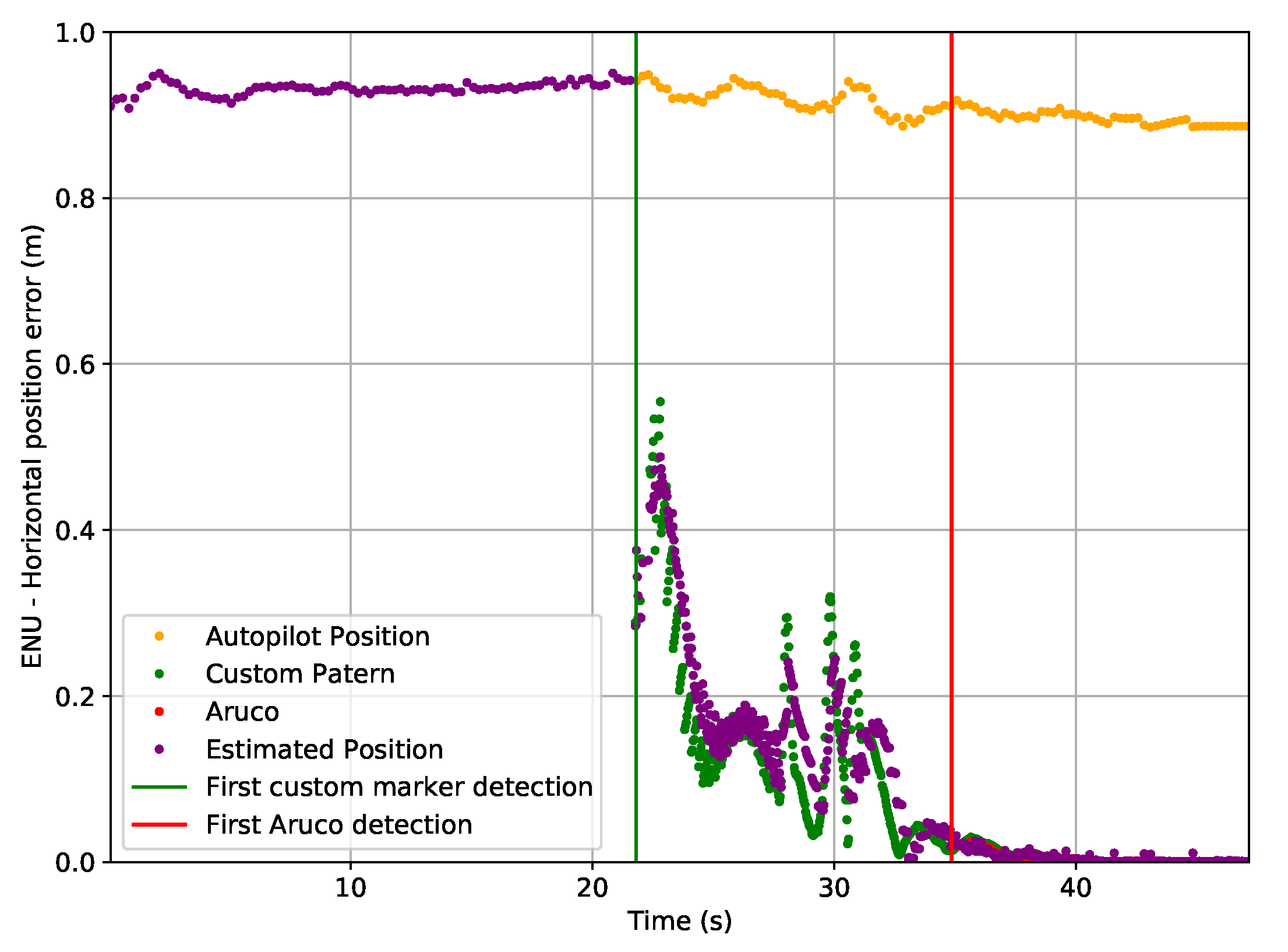
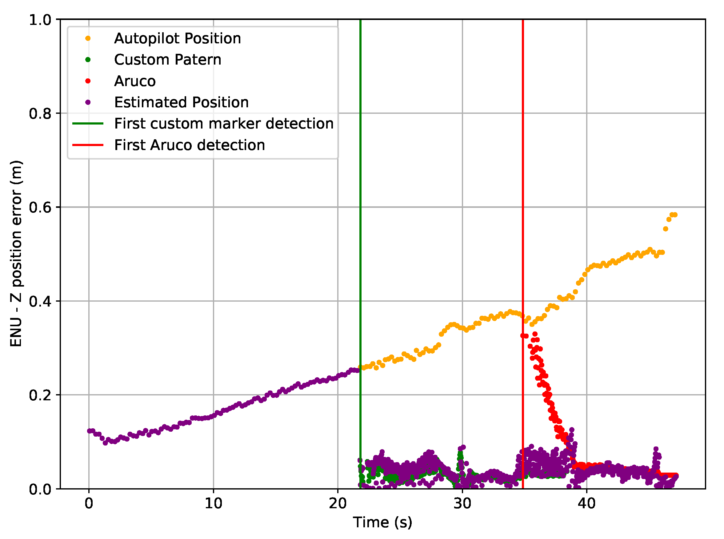
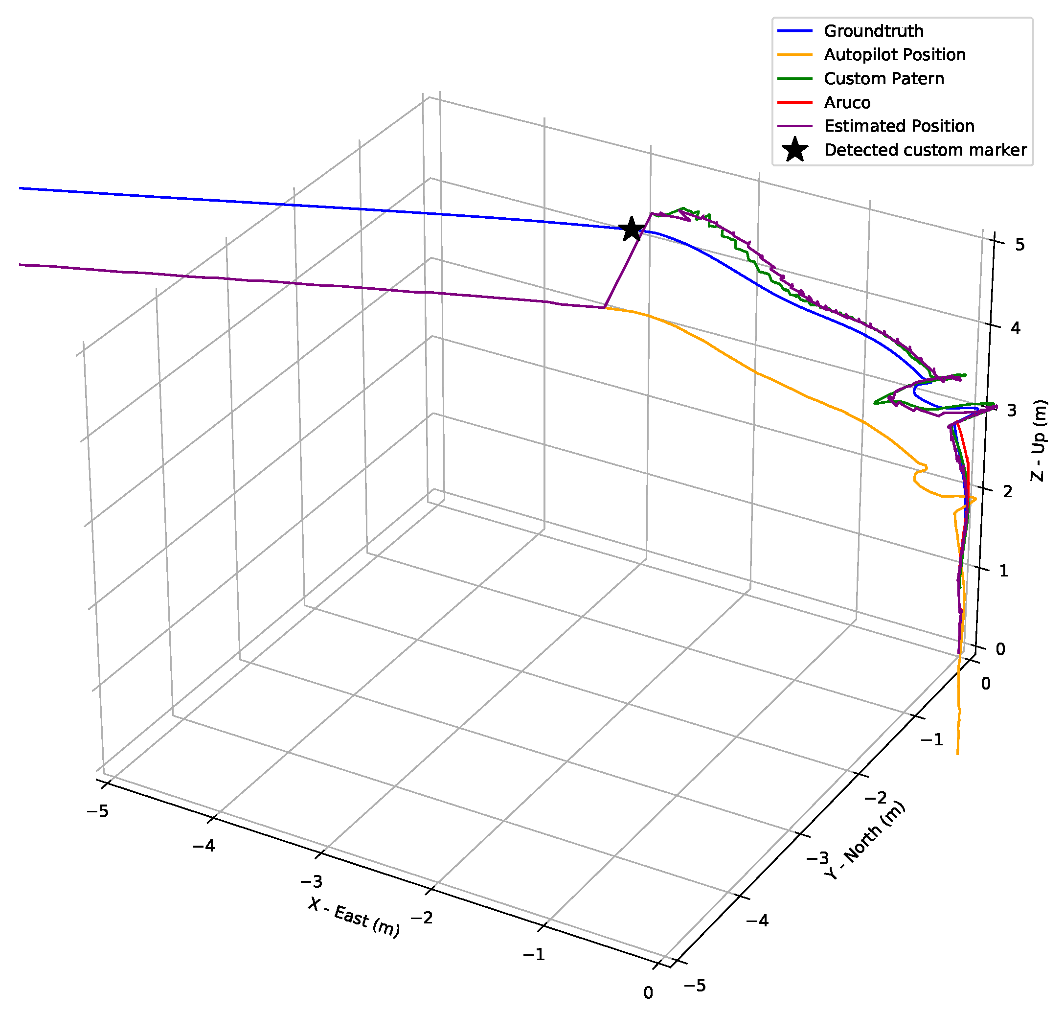
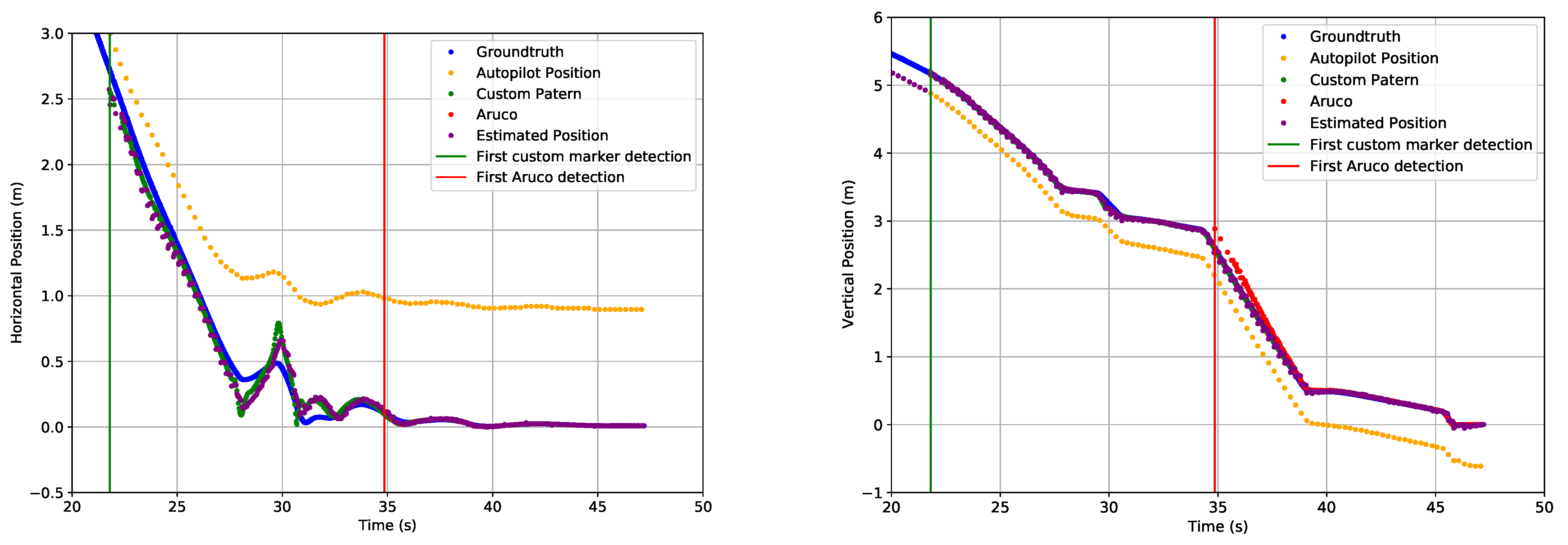
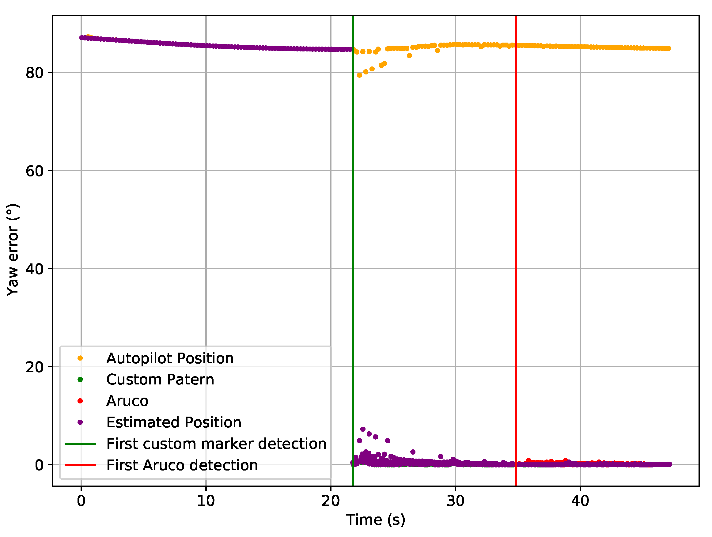
- Initially, only the GPS and IMU pose is used to compute the estimated pose.
- When hovering the landing pad, the custom pattern is detected, and the computer vision position aids the estimation of the position, reducing the position error.
- In the final stage, while all the three sources are used, the position error is even lower.
- On the Final Stage only the Autopilot and Aruco positions are used for the position estimation. Therefore, this line on the table represents only the position statistics for the final stage.
5. Discussion
- Pattern Detection—In order to exclude false positives, the verification rules are too strict, rejecting many frames even when the detection is successful.
- Aruco Detection—The detection of the Aruco has as input a black and white image. This black and white image is the result of a threshold of the Value channel. Currently, the threshold value is predefined and works most of the time. A new way to define the threshold value automatically could be used.
- Position Estimator—Currently, the estimator was tuned using information from the simulation data and needs to be tuned using real data.
- Control—As described previously, the control maneuver, although effective, is not smooth and fast enough. In the final step, the UAV takes a significant time to finish the maneuver (i.e., eight seconds to descend 25 cm).
6. Conclusions
7. Future Work
- Improve the threshold for the Aruco marker detection.
- Use a different computer vision position technique that can compute the roll and pitch of the UAV.
- Improve the maneuver control to make it smoother and faster, especially on the final step, when the visual pattern is detected.
- HEIFU 5G connectivity chip on board.
- Adaption of the ecosystem for the medical area for critical transportation of assets between clinics and hospitals.
- Benchmark of performance updates with the integration of sonar to the landing routine.
- Remote visualization and configuration of the landing area sensors via the beXStream platform.
- Modification of the Landing Area to study other types of UAVs such as Hybrid VTOLs (with multirotor and fixed-wing).
Author Contributions
Funding
Institutional Review Board Statement
Informed Consent Statement
Data Availability Statement
Acknowledgments
Conflicts of Interest
Abbreviations
| API | Application Programming Interface |
| CPU | Central Processing Unit |
| CUDA | Compute Unified Device Architecture |
| FOV | Field-Of-View |
| FPS | Frames Per Second |
| GNSS | Global Navigation Satellite System |
| GPS | Global Positioning System |
| GPU | Graphics Processing Unit |
| LED | Light Emitting Diode |
| LiDAR | Light Detection And Ranging |
| HEIFU | Hexa Exterior Intelligent Flying Unit |
| HSV | Hue Saturation Value |
| IMU | Inertial Measurement Unit |
| MPPT | Maximum Power Point Tracker |
| NAT | Network Address Translation |
| OBC | On Board Computer |
| QR | Quick Response |
| REST | Representational state transfer |
| RF | Radio Frequency |
| RGB | Red Green Blue |
| ROS | Robot Operating System |
| RTK | Real Time Kinematics |
| RTP | Real-time Transport Protocol |
| RTSP | Real-time Streaming Protocol |
| RTT | Round Trip Time |
| STUN | Session Traversal of UDP Through NAT |
| TURN | Traversal using Relays around NAT |
| UAV | Unmanned Aerial Vehicle |
| UDP | User Datagram Protocol |
| UHF | Ultra High Frequency |
| URLLC | Ultra Relieable Low Latency Communications |
| VTOL | Vertical Take-off and Landing |
| WebRTC | Real-Time Communication |
| WSS | WebSocket Secure |
References
- Ahirwar, S.; Swarnkar, R.; Bhukya, S.; Namwade, G. Application of Drone in Agriculture. Int. J. Curr. Microbiol. Appl. Sci. 2019, 8, 2500–2505. [Google Scholar] [CrossRef]
- Radoglou Grammatikis, P.; Sarigiannidis, P.; Lagkas, T.; Moscholios, I. A Compilation of UAV Applications for Precision Agriculture. Comput. Netw. 2020, 172, 107148. [Google Scholar] [CrossRef]
- Li, X.; Savkin, A.V. Networked Unmanned Aerial Vehicles for Surveillance and Monitoring: A Survey. Future Internet 2021, 13, 174. [Google Scholar] [CrossRef]
- Shakhatreh, H.; Sawalmeh, A.H.; Al-Fuqaha, A.; Dou, Z.; Almaita, E.; Khalil, I.; Othman, N.S.; Khreishah, A.; Guizani, M. Unmanned Aerial Vehicles (UAVs): A Survey on Civil Applications and Key Research Challenges. IEEE Access 2019, 7, 48572–48634. [Google Scholar] [CrossRef]
- Pedro, D.; Matos-Carvalho, J.P.; Azevedo, F.; Sacoto-Martins, R.; Bernardo, L.; Campos, L.; Fonseca, J.M.; Mora, A. FFAU—Framework for Fully Autonomous UAVs. Remote Sens. 2020, 12, 3533. [Google Scholar] [CrossRef]
- Azevedo, F.; Dias, A.; Almeida, J.; Oliveira, A.; Ferreira, A.; Santos, T.; Martins, A.; Silva, E. LiDAR-Based Real-Time Detection and Modeling of Power Lines for Unmanned Aerial Vehicles. Sensors 2019, 19, 1812. [Google Scholar] [CrossRef] [Green Version]
- Pedro, D.; Matos-Carvalho, J.P.; Fonseca, J.M.; Mora, A. Collision Avoidance on Unmanned Aerial Vehicles Using Neural Network Pipelines and Flow Clustering Techniques. Remote Sens. 2021, 13, 2643. [Google Scholar] [CrossRef]
- Van der Merwe, D.; Burchfield, D.R.; Witt, T.D.; Price, K.P.; Sharda, A. Drones in agriculture. In Advances in Agronomy; Academic Press: Cambridge, MA, USA, 2020. [Google Scholar] [CrossRef]
- Bravo, G.C.; Parra, D.M.; Mendes, L.; De Jesus Pereira, A.M. First aid drone for outdoor sports activities. In Proceedings of the TISHW 2016—1st International Conference on Technology and Innovation in Sports, Health and Wellbeing, Vila Real, Portugal, 1–3 December 2016. [Google Scholar] [CrossRef]
- Sanjana, P.; Prathilothamai, M. Drone Design for First Aid Kit Delivery in Emergency Situation. In Proceedings of the 2020 6th International Conference on Advanced Computing and Communication Systems, ICACCS 2020, Coimbatore, India, 6–7 March 2020. [Google Scholar] [CrossRef]
- Sousa, P.; Ferreira, A.; Moreira, M.; Santos, T.; Martins, A.; Dias, A.; Almeida, J.; Silva, E. ISEP/INESC TEC Aerial Robotics Team for Search and Rescue Operations at the EuRathlon Challenge 2015. In Proceedings of the 2016 International Conference on Autonomous Robot Systems and Competitions (ICARSC), Bragança, Portugal, 4–6 May 2016; pp. 156–161. [Google Scholar] [CrossRef]
- Almeida, J.; Ferreira, A.; Matias, B.; Dias, A.; Martins, A.; Silva, F.; Oliveira, J.; Sousa, P.; Moreira, M.; Miranda, T.; et al. Air and underwater survey of water enclosed spaces for VAMOS! Project. In Proceedings of the OCEANS 2016 MTS/IEEE Monterey, Monterey, CA, USA, 19–23 September 2016; pp. 1–5. [Google Scholar] [CrossRef]
- Gallo, I.G.; Martínez-Corbella, M.; Sarro, R.; Iovine, G.; López-Vinielles, J.; Hérnandez, M.; Robustelli, G.; Mateos, R.M.; García-Davalillo, J.C. An Integration of UAV-Based Photogrammetry and 3D Modelling for Rockfall Hazard Assessment: The Cárcavos Case in 2018 (Spain). Remote Sens. 2021, 13, 3450. [Google Scholar] [CrossRef]
- Singh, A.K.; Swarup, A.; Agarwal, A.; Singh, D. Vision based rail track extraction and monitoring through drone imagery. ICT Express 2019, 5, 250–255. [Google Scholar] [CrossRef]
- Barreto, J.; Cajaíba, L.; Teixeira, J.B.; Nascimento, L.; Giacomo, A.; Barcelos, N.; Fettermann, T.; Martins, A. Drone-monitoring: Improving the detectability of threatened marine megafauna. Drones 2021, 5, 14. [Google Scholar] [CrossRef]
- Pedro, D.; Mora, A.; Carvalho, J.; Azevedo, F.; Fonseca, J. ColANet: A UAV Collision Avoidance Dataset. In Technological Innovation for Life Improvement; Camarinha-Matos, L.M., Farhadi, N., Lopes, F., Pereira, H., Eds.; Springer International Publishing: Cham, Switzerland, 2020; pp. 53–62. [Google Scholar]
- Azevedo, F.; Cardoso, J.S.; Ferreira, A.; Fernandes, T.; Moreira, M.; Campos, L. Efficient Reactive Obstacle Avoidance Using Spirals for Escape. Drones 2021, 5, 51. [Google Scholar] [CrossRef]
- Allasia, P.; Baldo, M.; Giordan, D.; Godone, D.; Wrzesniak, A.; Lollino, G. Near Real Time Monitoring Systems and Periodic Surveys Using a Multi Sensors UAV: The Case of Ponzano Landslide. In Proceedings of the IAEG/AEG Annual Meeting Proceedings, San Francisco, CA, USA, 17–21 September 2018; Volume 1. [Google Scholar] [CrossRef]
- Nenni, M.E.; Di Pasquale, V.; Miranda, S.; Riemma, S. Development of a Drone-Supported Emergency Medical Service. Int. J. Technol. 2020, 11, 656–666. [Google Scholar] [CrossRef]
- Ballous, K.A.; Khalifa, A.N.; Abdulwadood, A.A.; Al-Shabi, M.; El Haj Assad, M. Medical kit: Emergency drone. In Unmanned Systems Technology XXII; International Society for Optics and Photonics: Bellingham, WA, USA, 2020. [Google Scholar] [CrossRef]
- Nafiz Hasan Khan, M.; Neustaedter, C. An exploratory study of the use of drones for assisting firefighters during emergency situations. In Proceedings of the Conference on Human Factors in Computing Systems, Glasgow, UK, 4–9 May 2019. [Google Scholar] [CrossRef]
- Aravindadhith, P.S. Design and Fabrication of Emergency Drone Recovery System. Int. J. Eng. Adv. Technol. 2020, 9, 424–427. [Google Scholar] [CrossRef]
- Dardoize, T.; Ciochetto, N.; Hong, J.; Shin, H. Implementation of Ground Control System for Autonomous Multi-agents using QGroundControl. In Proceedings of the 2019 Workshop on Research, Education and Development of Unmanned Aerial Systems (RED UAS), Cranfield, UK, 25–27 November 2019; pp. 24–30. [Google Scholar]
- PX4. Available online: https://px4.io/ (accessed on 23 August 2021).
- Ardupilot. Available online: https://ardupilot.org/ (accessed on 23 August 2021).
- Pino, M.; Matos-Carvalho, J.P.; Pedro, D.; Campos, L.M.; Costa Seco, J. UAV Cloud Platform for Precision Farming. In Proceedings of the 2020 12th International Symposium on Communication Systems, Networks and Digital Signal Processing (CSNDSP), Porto, Portugal, 20–22 July 2020; pp. 1–6. [Google Scholar] [CrossRef]
- FlytOS. Available online: https://flytbase.com/flytos/ (accessed on 12 July 2021).
- Yanmaz, E.; Yahyanejad, S.; Rinner, B.; Hellwagner, H.; Bettstetter, C. Drone networks: Communications, coordination, and sensing. Ad. Hoc. Netw. 2018, 68, 1–15. [Google Scholar] [CrossRef]
- Ollero, A.; Lacroix, S.; Merino, L.; Gancet, J.; Wiklund, J.; Remuss, V.; Perez, I.V.; Gutierrez, L.G.; Viegas, D.X.; Benitez, M.A.G.; et al. Multiple eyes in the skies: Architecture and perception issues in the COMETS unmanned air vehicles project. IEEE Robot. Autom. Mag. 2005, 12, 46–57. [Google Scholar] [CrossRef]
- Gupta, L.; Jain, R.; Vaszkun, G. Survey of Important Issues in UAV Communication Networks. IEEE Commun. Surv. Tutor. 2016, 18, 1123–1152. [Google Scholar] [CrossRef] [Green Version]
- Ebeid, E.; Skriver, M.; Terkildsen, K.H.; Jensen, K.; Schultz, U.P. A survey of Open-Source UAV flight controllers and flight simulators. Microprocess. Microsyst. 2018, 61, 11–20. [Google Scholar] [CrossRef]
- Matos-Carvalho, J.P.; Fonseca, J.M.; Mora, A. UAV Downwash Dynamic Texture Features for Terrain Classification on Autonomous Navigation. In Proceedings of the 2018 Federated Conference on Computer Science and Information Systems (FedCSIS), Poznań, Poland, 9–12 September 2018; pp. 1079–1083. [Google Scholar]
- Prates, P.A.; Mendonça, R.; Lourenço, A.; Marques, F.; Matos-Carvalho, J.P.; Barata, J. Vision-based UAV detection and tracking using motion signatures. In Proceedings of the 2018 IEEE Industrial Cyber-Physical Systems (ICPS), Saint Petersburg, Russia, 15–18 May 2018; pp. 482–487. [Google Scholar] [CrossRef]
- Azevedo, F.; Oliveira, A.; Dias, A.; Almeida, J.; Moreira, M.; Santos, T.; Ferreira, A.; Martins, A.; Silva, E. Collision avoidance for safe structure inspection with multirotor UAV. In Proceedings of the 2017 European Conference on Mobile Robots (ECMR), Paris, France, 6–8 September 2017; pp. 1–7. [Google Scholar] [CrossRef] [Green Version]
- Mourgelas, C.; Kokkinos, S.; Milidonis, A.; Voyiatzis, I. Autonomous Drone Charging Stations: A Survey. In Proceedings of the 24th Pan-Hellenic Conference on Informatics, Athens, Greece, 20–22 November 2020; pp. 233–236. [Google Scholar] [CrossRef]
- Galimov, M.; Fedorenko, R.; Klimchik, A. UAV Positioning Mechanisms in Landing Stations: Classification and Engineering Design Review. Sensors 2020, 20, 3648. [Google Scholar] [CrossRef]
- Identified Technologies. Autonomous Mapping Boomerang Drone and Docking Charging Station; Identified Technologies: Pittsburgh, PA, USA, 2021. [Google Scholar]
- Hextronics. Hextronics Global; Hextronics: Atlanta, GE, USA, 2021. [Google Scholar]
- Skycharge. Indoor Drone Charging Pad and Infrastructure; Skycharge: Berlin, Germany, 2021. [Google Scholar]
- Airscort Ltd. ST-1200; Airscort Ltd.: Jerusalem, Israel, 2021. [Google Scholar]
- Noon. 21st Century (1221). UAV Docking Station; Noon. 21st Century (1221): Moscow, Russia. Available online: https://1221.su/uav-docking-station/ (accessed on 30 July 2021).
- Morim, M.M. Sistema de Apoio ao Processo de Aterragem Autónoma de um VTOL. Master’s Thesis, Instituto Superior de Engenharia do Porto, Departamento de Engenharia Eletrotécnica, Porto, Portugal, 2017. [Google Scholar]
- Wubben, J.; Fabra, F.; Calafate, C.T.; Krzeszowski, T.; Marquez-Barja, J.M.; Cano, J.C.; Manzoni, P. Accurate Landing of Unmanned Aerial Vehicles Using Ground Pattern Recognition. Electronics 2019, 8, 1532. [Google Scholar] [CrossRef] [Green Version]
- He, K.; Weng, D.; Ji, S.; Wang, Z.; Chen, W.; Lu, Y.; Nie, Z. Improving the Performance of Time-Relative GNSS Precise Positioning in Remote Areas. Sensors 2021, 21, 292. [Google Scholar] [CrossRef]
- Abbas, S.M.; Aslam, S.; Berns, K.; Muhammad, A. Analysis and Improvements in AprilTag Based State Estimation. Sensors 2019, 19, 5480. [Google Scholar] [CrossRef] [Green Version]
- Xing, B.; Zhu, Q.; Pan, F.; Feng, X. Marker-Based Multi-Sensor Fusion Indoor Localization System for Micro Air Vehicles. Sensors 2018, 18, 1706. [Google Scholar] [CrossRef] [Green Version]
- Yang, S.; Scherer, S.A.; Schauwecker, K.; Zell, A. Onboard monocular vision for landing of an MAV on a landing site specified by a single reference image. In Proceedings of the 2013 International Conference on Unmanned Aircraft Systems (ICUAS), Atlanta, GE, USA, 28–31 May 2013; pp. 318–325. [Google Scholar] [CrossRef]
- Jung, Y.; Bang, H.; Lee, D. Robust marker tracking algorithm for precise UAV vision-based autonomous landing. In Proceedings of the 2015 15th International Conference on Control, Automation and Systems (ICCAS), Busan, Korea, 13–16 October 2015; pp. 443–446. [Google Scholar] [CrossRef]
- Demirhan, M.; Premachandra, C. Development of an Automated Camera-Based Drone Landing System. IEEE Access 2020, 8, 202111–202121. [Google Scholar] [CrossRef]
- Cocchioni, F.; Mancini, A.; Longhi, S. Autonomous navigation, landing and recharge of a quadrotor using artificial vision. In Proceedings of the 2014 International Conference on Unmanned Aircraft Systems (ICUAS), Orlando, FL, USA, 27–30 May 2014; pp. 418–429. [Google Scholar] [CrossRef]
- Hui, C.; Yousheng, C.; Xiaokun, L.; Shing, W.W. Autonomous takeoff, tracking and landing of a UAV on a moving UGV using onboard monocular vision. In Proceedings of the 32nd Chinese Control Conference, Xi’an, China, 26–28 July 2013; pp. 5895–5901. [Google Scholar]
- Fitzgibbon, A.; Pilu, M.; Fisher, R.B. Direct least square fitting of ellipses. IEEE Trans. Pattern Anal. Mach. Intell. 1999, 21, 476–480. [Google Scholar] [CrossRef] [Green Version]
- Huang, C.M.; Hung, T.S. Visual servoing of micro aerial vehicle landing on ground platform. In Proceedings of the 2014 IEEE International Conference on Systems, Man, and Cybernetics (SMC), Diego, CA, USA, 5–8 October 2014; pp. 2071–2076. [Google Scholar] [CrossRef]
- Koo, T.J.; Sastry, S. Hybrid control of unmanned aerial vehicles for autonomous landing. In Proceedings of the 2nd AIAA “Unmanned Unlimited” Conference and Workshop and Exhibit, San Diego, CA, USA, 15–18 September 2003. [Google Scholar] [CrossRef]
- Cocchioni, F.; Frontoni, E.; Ippoliti, G.; Longhi, S.; Mancini, A.; Zingaretti, P. Visual Based Landing for an Unmanned Quadrotor. J. Intell. Robot. Syst. Theory Appl. 2016, 84, 511–528. [Google Scholar] [CrossRef]
- Censi, A.; Strubel, J.; Brandli, C.; Delbruck, T.; Scaramuzza, D. Low-latency localization by active LED markers tracking using a dynamic vision sensor. In Proceedings of the 2013 IEEE/RSJ International Conference on Intelligent Robots and Systems, Tokyo, Japan, 3–7 November 2013; pp. 891–898. [Google Scholar] [CrossRef] [Green Version]
- Okano, Y.; Ito, Y. LED marker position detection using Walsh Functions. In Proceedings of the 2010 International Symposium on Intelligent Signal Processing and Communication Systems, Naha, Japan, 6–8 December 2010; pp. 1–4. [Google Scholar] [CrossRef]
- Breitenmoser, A.; Kneip, L.; Siegwart, R. A monocular vision-based system for 6D relative robot localization. In Proceedings of the 2011 IEEE/RSJ International Conference on Intelligent Robots and Systems, San Francisco, CA, USA, 25–30 September 2011; pp. 79–85. [Google Scholar] [CrossRef] [Green Version]
- Wang, X.-H.; Xu, G.-L.; Tian, Y.-P.; Wang, B.; Wang, J.-D. UAV’s Automatic Landing in All Weather Based on the Cooperative Object and Computer Vision. In Proceedings of the 2012 Second International Conference on Instrumentation, Measurement, Computer, Communication and Control, Harbin, China, 8–10 December 2012; pp. 1346–1351. [Google Scholar] [CrossRef]
- Wenzel, K.E.; Masselli, A.; Zell, A. Automatic Take Off, Tracking and Landing of a Miniature UAV on a Moving Carrier Vehicle. J. Intell. Robot. Syst. 2011, 61, 221–238. [Google Scholar] [CrossRef] [Green Version]
- Khithov, V.; Petrov, A.; Tishchenko, I.; Yakovlev, K. Toward autonomous UAV landing based on infrared beacons and particle filtering. In Robot Intelligence Technology and Applications; Springer: Cham, Switzerland, 2017. [Google Scholar] [CrossRef] [Green Version]
- Kim, D.; Choi, J. Multi-robot team outdoor localization using active marker and high frequency signal sources. In Proceedings of the 2011 11th International Conference on Control, Automation and Systems, Gyeonggi-do, Korea, 26–29 October 2011; pp. 192–196. [Google Scholar]
- Xu, Z.C.; Hu, B.B.; Liu, B.; Wang, X.D.; Zhang, H.T. Vision-based Autonomous Landing of Unmanned Aerial Vehicle on a Motional Unmanned Surface Vessel. In Proceedings of the 2020 39th Chinese Control Conference (CCC), Shenyang, China, 27–29 July 2020; pp. 6845–6850. [Google Scholar] [CrossRef]
- Fu, M.; Zhang, K.; Yi, Y.; Shi, C. Autonomous landing of a quadrotor on an UGV. In Proceedings of the 2016 IEEE International Conference on Mechatronics and Automation, Harbin, China, 7–10 August 2016; pp. 988–993. [Google Scholar] [CrossRef]
- Grobler, P.R.; Jordaan, H.W. Autonomous Vision Based Landing Strategy for a Rotary Wing UAV. In Proceedings of the 2020 International SAUPEC/RobMech/PRASA Conference, Cape Town, South Africa, 29–31 January 2020; pp. 1–6. [Google Scholar] [CrossRef]
- Aalerud, A.; Dybedal, J.; Hovland, G. Automatic Calibration of an Industrial RGB-D Camera Network Using Retroreflective Fiducial Markers. Sensors 2019, 19, 1561. [Google Scholar] [CrossRef] [PubMed] [Green Version]
- Zhang, Y.; Yu, Y.; Jia, S.; Wang, X. Autonomous landing on ground target of UAV by using image-based visual servo control. In Proceedings of the 2017 36th Chinese Control Conference (CCC), Dalian, China, 26–28 July 2017; pp. 11204–11209. [Google Scholar] [CrossRef]
- influxDB. 2021. Available online: https://www.influxdata.com/ (accessed on 30 July 2021).
- beXStream. 2021. Available online: https://x-stream.github.io/ (accessed on 30 July 2021).
- Amirante, A.; Castaldi, T.; Miniero, L.; Romano, S.P. Janus: A general purpose WebRTC gateway. In Proceedings of the Conference on Principles, Systems and Applications of IP Telecommunications, IPTComm 2014, Chicago, IL, USA, 1–2 October 2014. [Google Scholar] [CrossRef] [Green Version]
- Sacoto-Martins, R.; Madeira, J.; Matos-Carvalho, J.P.; Azevedo, F.; Campos, L.M. Multi-purpose Low Latency Streaming Using Unmanned Aerial Vehicles. In Proceedings of the 2020 12th International Symposium on Communication Systems, Networks and Digital Signal Processing (CSNDSP), Porto, Portugal, 20–22 July 2020; pp. 1–6. [Google Scholar] [CrossRef]
- Hanhart, P.; He, Y.; Ye, Y.; Boyce, J.; Deng, Z.; Xu, L. 360-Degree Video Quality Evaluation. In Proceedings of the 2018 Picture Coding Symposium, PCS 2018, San Francisco, CA, USA, 24–27 June 2018. [Google Scholar] [CrossRef]
- Popovski, P.; Stefanovic, C.; Nielsen, J.J.; de Carvalho, E.; Angjelichinoski, M.; Trillingsgaard, K.F.; Bana, A.S. Wireless Access in Ultra-Reliable Low-Latency Communication (URLLC). IEEE Trans. Commun. 2019, 67, 5783–5801. [Google Scholar] [CrossRef] [Green Version]
- Janczukowicz, E.; Braud, A.; Tuffin, S.; Fromentoux, G.; Bouabdallah, A.; Bonnin, J.M. Specialized network services for WebRTC: TURN-based architecture proposal. In Proceedings of the 1st Workshop on All-Web Real-Time Systems, AweS 2015—In Conjunction with EuroSys 2015, Bordeaux, France, 21 April 2015. [Google Scholar] [CrossRef]
- U-blox. ZED-F9P Module u-blox F9 High Precision GNSS Module; U-blox: Thalwil, Switzerland, 2019. [Google Scholar]
- Aeriya. beRTK; Aeriya: Alfragide, Portugal, 2021. [Google Scholar]
- Pathak, S.V.; Mohod, A.G.; Sawant, A.A. Review on effective role of UAV in precision farming. J. Pharmacogn. Phytochem. 2020, 9, 463–467. [Google Scholar]
- Romero-Ramirez, F.; Muñoz-Salinas, R.; Medina-Carnicer, R. Speeded Up Detection of Squared Fiducial Markers. Image Vis. Comput. 2018, 76, 38–47. [Google Scholar] [CrossRef]
- Garrido-Jurado, S.; Muñoz-Salinas, R.; Madrid-Cuevas, F.; Medina-Carnicer, R. Generation of fiducial marker dictionaries using Mixed Integer Linear Programming. Pattern Recognit. 2015, 51, 481–491. [Google Scholar] [CrossRef]
- Carvalho, J.P.L.A.d.M. Improved Terrain Type Classification Using UAV Downwash Dynamic Texture Effect. Ph.D. Thesis, Faculdade de Ciências e Tecnologia (FCT), Universidade Lusófona, Lisbon, Portugal, 2021. [Google Scholar]
- Krig, S. Computer Vision Metrics; Springer: Berlin/Heidelberg, Germany, 2016. [Google Scholar] [CrossRef]
- OpenCV. 2021. Available online: https://opencv.org/ (accessed on 30 July 2021).
- Lloyd, S. Least squares quantization in PCM. IEEE Trans. Inf. Theory 1982, 28, 129–137. [Google Scholar] [CrossRef]
- Matos-Carvalho, J.P.; Santos, R.; Tomic, S.; Beko, M. GTRS-Based Algorithm for UAV Navigation in Indoor Environments Employing Range Measurements and Odometry. IEEE Access 2021, 9, 89120–89132. [Google Scholar] [CrossRef]
- Nakama, J.; Parada, R.; Matos-Carvalho, J.P.; Azevedo, F.; Pedro, D.; Campos, L. Autonomous Environment Generator for UAV-Based Simulation. Appl. Sci. 2021, 11, 2185. [Google Scholar] [CrossRef]
- Koenig, N.; Howard, A. Design and use paradigms for Gazebo, an open-source multi-robot simulator. In Proceedings of the 2004 IEEE/RSJ International Conference on Intelligent Robots and Systems (IROS) (IEEE Cat. No.04CH37566), Sendai, Japan, 28 September–2 October 2004; Volume 3, pp. 2149–2154. [Google Scholar] [CrossRef] [Green Version]
- Matos-Carvalho, J.P.; Pedro, D.; Campos, L.M.; Fonseca, J.M.; Mora, A. Terrain Classification Using W-K Filter and 3D Navigation with Static Collision Avoidance. In Intelligent Systems and Applications; Bi, Y., Bhatia, R., Kapoor, S., Eds.; Springer International Publishing: Cham, Switzerland, 2020; pp. 1122–1137. [Google Scholar]
- Kam, H.; Lee, S.H.; Park, T.; Kim, C.H. RViz: A toolkit for real domain data visualization. Telecommun. Syst. 2015, 60, 1–9. [Google Scholar] [CrossRef]
- Yoakum, C.; Cerreta, J. A Review of DJI’s Mavic Pro Precision Landing Accuracy. Int. J. Aviat. Aeronaut. Aerosp. 2020, 7, 1–19. [Google Scholar] [CrossRef]
- Goncalves, V.M.; Mclaughlin, R.; Pereira, G.A. Precise Landing of Autonomous Aerial Vehicles Using Vector Fields. IEEE Robot. Autom. Lett. 2020, 5, 4337–4344. [Google Scholar] [CrossRef]
- Wang, J.; McKiver, D.; Pandit, S.; Abdelzaher, A.F.; Washington, J.; Chen, W. Precision UAV Landing Control Based on Visual Detection. In Proceedings of the 3rd International Conference on Multimedia Information Processing and Retrieval, MIPR 2020, San Jose, CA, USA, 6–8 August 2020; pp. 205–208. [Google Scholar] [CrossRef]
- Patruno, C.; Nitti, M.; Petitti, A.; Stella, E.; D’Orazio, T. A Vision-Based Approach for Unmanned Aerial Vehicle Landing. J. Intell. Robot. Syst. Theory Appl. 2019, 95, 645–664. [Google Scholar] [CrossRef]


| Source | Horizontal (m) | Vertical (m) | Heading () |
|---|---|---|---|
| GPS and IMU | 0.918 ± 0.017 | 0.286 ± 0.129 | 85.283 ± 0.785 |
| Custom Marker | 0.116 ± 0.113 | 0.029 ± 0.011 | 0.124 ± 0.157 |
| Aruco | 0.004 ± 0.006 | 0.078 ± 0.074 | 0.155 ± 0.136 |
| Source | Horizontal (m) | Vertical (m) | Heading () |
|---|---|---|---|
| Only GPS and IMU | 0.931 ± 0.007 | 0.169 ± 0.047 | 85.544 ± 0.738 |
| With Pattern | 0.304 ± 0.314 | 0.060 ± 0.058 | 16.137 ± 32.999 |
| All sources | 0.173 ± 0.278 | 0.052 ± 0.046 | 9.066 ± 25.949 |
| Final Stage | 0.005 ± 0.006 | 0.041 ± 0.019 | 0.069 ± 0.061 |
Publisher’s Note: MDPI stays neutral with regard to jurisdictional claims in published maps and institutional affiliations. |
© 2021 by the authors. Licensee MDPI, Basel, Switzerland. This article is an open access article distributed under the terms and conditions of the Creative Commons Attribution (CC BY) license (https://creativecommons.org/licenses/by/4.0/).
Share and Cite
Moreira, M.; Azevedo, F.; Ferreira, A.; Pedro, D.; Matos-Carvalho, J.; Ramos, Á.; Loureiro, R.; Campos, L. Precision Landing for Low-Maintenance Remote Operations with UAVs. Drones 2021, 5, 103. https://doi.org/10.3390/drones5040103
Moreira M, Azevedo F, Ferreira A, Pedro D, Matos-Carvalho J, Ramos Á, Loureiro R, Campos L. Precision Landing for Low-Maintenance Remote Operations with UAVs. Drones. 2021; 5(4):103. https://doi.org/10.3390/drones5040103
Chicago/Turabian StyleMoreira, Miguel, Fábio Azevedo, André Ferreira, Dário Pedro, João Matos-Carvalho, Álvaro Ramos, Rui Loureiro, and Luís Campos. 2021. "Precision Landing for Low-Maintenance Remote Operations with UAVs" Drones 5, no. 4: 103. https://doi.org/10.3390/drones5040103
APA StyleMoreira, M., Azevedo, F., Ferreira, A., Pedro, D., Matos-Carvalho, J., Ramos, Á., Loureiro, R., & Campos, L. (2021). Precision Landing for Low-Maintenance Remote Operations with UAVs. Drones, 5(4), 103. https://doi.org/10.3390/drones5040103