
Power Line Charging Mechanism for Drones


Kinematics and Computational Geometry Laboratory, Department of Computer Science, Ariel University, Ari’el 40700, Israel
Drones 2021, 5(4), 108; https://doi.org/10.3390/drones5040108
Submission received: 22 August 2021
/
Revised: 25 September 2021
/
Accepted: 25 September 2021
/
Published: 1 October 2021
(This article belongs to the Special Issue Conceptual Design, Modeling, and Control Strategies of Drones)
Abstract
:The use of multirotor drones has increased dramatically in the last decade. These days, quadcopters and Vertical Takeoff and Landing (VTOL) drones can be found in many applications such as search and rescue, inspection, commercial photography, intelligence, sports, and recreation. One of the major drawbacks of electric multirotor drones is their limited flight time. Commercial drones commonly have about 20–40 min of flight time. The short flight time limits the overall usability of drones in homeland security applications where long-duration performance is required. In this paper, we present a new concept of a “power-line-charging drone”, the idea being to equip existing drones with a robotic mechanism and an onboard charger in order to allow them to land safely on power lines and then charge from the existing 100–250 V AC (50–60 Hz). This research presents several possible conceptual models for power line charging. All suggested solutions were constructed and submitted to a field experiment. Finally, the paper focuses on the optimal solution and presents the performance and possible future development of such power-line-charging drones.
1. Introduction
In this work, we present a complete proof of concept of a robotic mechanism that allows a VTOL drone to be charged from power lines. Motivated by the demanding challenge of constructing a long-duration multirotor platform, we designed an “add-on” mechanism that allows a commercial drone to safely land on power lines, perform a short-term charging loop (in 1–2 C), and finally, take off safely from the power line. Figure 1 represents the overall concept of the suggested power line charging mechanism for drones.
1.1. Related Works
The topic of maximizing the flight time of drones and UAVs has attracted the attention of many researches; see [1,2]. The inspection of power lines is commonly performed using UAVs [3,4]. In order to be able to closely and safely inspect wires and power lines, there is a need to be able to detect, track, and map them in real time [5,6]. Several research works suggested wireless charging from power lines [7,8,9]. The use of a swarm of drones as a dynamic network infrastructure faces a related energy optimization challenge; see [10] for a recent paper regarding the main battery charging (energy harvesting) methods for such swarms. Recently, the concept of “drone-in-a-box” has become popular in many commercial and homeland security applications [11,12]. Several companies such as Skycharge [13], Heisha [14], and Flytbase [15] are offering after-market solutions for Commercial Off-The-Shelf (COTS) drones, allowing them to perform accurate landing on a charging pad. Alternatively, the concept of automatic battery swapping for drones has been suggested by a few researchers and companies [15,16,17]. The concept of “drone delivery” has motivated researchers to model optimization problems related to facility location [18] and vehicle routing [19]. In such cases, the goal is to locate a set of charging stations or battery swapping stations in a way that optimizes delivery performance (communally, time, or cost) [20,21,22]. Finally, the concept of energy harvesting for drones has attracted the attention of many researchers. The use of solar panels on a drone may allow some additional flight time [23,24], but this is mainly applicable to energy-efficient UAVs (i.e., VTOL drones are energy-inefficient by nature). Other methods of “in-air” charging include high-power laser (or mm-wave) long-range wireless charging [25]; however, such methods require the drone to be within the Line-Of-Site (LOS) of the charging station and raise major safety issues, so they are currently impractical for COTS drones. In this paper, we address the challenge of charging a drone on site, without any “charging station”. Moreover, unlike most energy-harvesting methods, which are usually slow and require a long charging period, in this paper, we focus on the use case of “in-mission rapid charging”.
1.2. Requirements
In general, a charging system for drones should satisfy the following requirements:
- Light weight: The overall flight time on a single charge should remain as close as possible to the original performance of the drone (without the charging mechanism), e.g., at least 85% of the original performance of the platform;
- Fast charging: The platform should allow a 2:1 charging vs. flying ratio (e.g., 30 min of charging should allow at least 15 min of extra flight time);
- Rapid landing and takeoff: In order to maximize the operational time, the overall landing and takeoff time should be less than 1 min;
- Safety: The charging tasks (landing, charging, and takeoff) should be safe and efficient, allowing a common operator to perform a complete charging process with a success probability greater than 99%;
- Remote operation: the operator should be able to perform the charging maneuver via First-Person Flight (FPV) control (no line-of-site) from a remote location, which might be a few kilometers away;
- Standard COTS platform: The charging platform should be able to be integrated with standard commercial drones.
1.3. Motivation
This research was motivated by the challenge of maximizing the operational performance of tactical drones. We were mainly motivated by the use case of wildfires, where drones are commonly used at the tactical level to help firefighters gain real-time information regarding the risks, changes in the fire, and post-fire analysis [26,27,28]. In the case of severe fires, a “risky” procedure such as power line charging might be seen as considerable, in particular if such an operation reduces the risk for firefighters. The use case of fighting wildfires often requires the continuous inspection of a wide region; thus, it is important to maximize the drone’s overall operational time. Moreover, it might be desired to allow the drone to land on a spot with good visibility, allowing it to inspect the region with very low energy consumption (telemetry transmission only). We observed that wires are often suitable spots for such landing and guarding applications, and in the case of low-voltage power lines, they can also serve as a charging source. This paper focuses on small commercial drones, which are widely used for such applications. While wireless methods for charging drones from high-voltage power lines have been suggested by several researchers [7,8,9], this requires additional, relatively heavy (onboard) components, in particular a coil. Moreover, this requires the drone to maintain flight (hovering) during the charging process, which requires additional charging power and very accurate hovering capabilities (above the power lines). For recent surveys on wireless-charging methods, see [7,29]. We were unable to design a reliable power-line wireless-charging mechanism for small drones; therefore, we limited the scope of this paper to direct (contact) charging of the drone from low-voltage power lines. We constructed the charging system and tested it in field experiments.
1.4. Our Contribution
This paper focuses on the challenge of charging a drone from low-voltage power lines using direct contact. The research presents several design concepts and discusses their performance in real-world experiments. This paper’s novelty is two-fold: (i) the new concept of “hook landing”, which allows basically any drone to land safely and efficiently on practically any horizontal wire (and take off from it later on); (ii) the new concept of robotic measuring tape, which allows the drone that lands on the wire to approach and contact another wire (power line) in its surroundings (e.g., up to 1 m away), then close the circle for charging. Both concepts were designed and installed on an existing COTS drone (DJI’s Matrice 100). The drone was able to safely land on a single wire, connect the robotic “meter arm” to the other wire, and perform a fast charging, resulting in 15 min of extra flight time using 15 min of charging. To the best of our knowledge, the “hook landing”, the 2DoF robotic measuring tape for charging, and the 1:1 ratio for charging/extra flight time are all new in the scope of commercial COTS drones and UAVs.
2. Onboard Charging Concept for Drones
In this section, we present the design concept of the onboard charger (for drones). In simple terms, one can take the drone’s regular charger and locate it on the drone. For that, we needed the following changes to the drone:
- We changed the AC socket: we connected the two wires of the charger to the pads that contacted the power lines (one to the ground and the other to the line);
- We located the charger onboard the drone;
- We connected the charger to the drone battery (or batteries).
In fact, the charger had two main components: (i) an AC to DC transformer; (ii) a DC battery charger. For simplicity and for safety testing, we started our design with a low-voltage DC charger (mainly 12–24 V). Figure 2 presents the very basic concepts of the modified drone.
Recently, new mini drones such as DJI’s Mavic mini, mini2, and miniSE, have allowed direct 5 V charging capabilities. Thus, one can modify one side of a USB charging cable (two wires) to connect to each of the legs, while the other side of the cable can be permanently connected to the USB charging port. This relatively simple modification allows cost-effective “drone-in-a-box” solutions.
The need to add an AC to DC transformer and the nature of unisolated low-voltage (100–250 V) power lines, which are commonly at least 40 cm apart, limit the use of microdrones (with weight below 1–2 kg). Therefore, we focused on relatively large drones of 2–10 kg that are applicable to real-world power line charging.
3. Power Line Landing Mechanisms
In this section, we cover the topic of landing on wires (power lines). The first wire-landing method is the natural vertical landing approach, which basically uses two parallel wires as a “landing pad”; this requires adjustable skids, (see Figure 3, Figure 4 and Figure 5). Next, we present a rotation landing, which is based on a “T-shaped” drone (see Figure 6) that approaches the wires from below; once the bar is above the two wires, it rotates 90 and lands. Finally, The concept of “hook landing” is presented; this method uses a vertical pole with a “hook” to land on a single wire with a horizontal approach. This method is by far the most efficient, and therefore, it was chosen to be implemented in the advanced mode.
3.1. Vertical Landing
A natural way of landing on wires is to try to approach the wires from above (vertical landing) and use some kind of skid to safely rest on the two wires (see Figure 4 and Figure 5. As all the other methods of landing on wires, the drone uses GPS (GNSS) to perform a “position hold”, and the operator aligns the drone above the center of the two wires, then slowly reduces the drones height, until it tor uches and lands on the two wires.
3.2. Rotation Landing
In this landing method (on wires), the drone has a “T-shaped” structure. The drone approaches the power lines from underneath. First, the drone rotates so that the “T shape” will be parallel with the two wires (in the center below them). Then, the drone elevates itself until the “T” is slightly above the two wires (the drone frame is below the wires). Finally, the drone rotates 90 and lands on the wires. Figure 6 demonstrates such a landing. Note that the takeoff process is performed in the reverse order.
3.3. Hook Landing Drone
The first two power line landing methods have the following major drawbacks: (i) Vertical landing requires two leveled wires, with some fixed distance. This is often not the case for suburban low-voltage power line infrastructure, which is commonly vertical (or simply has unleveled wires). (ii) Rotation landing requires clear access from below the wires, which are commonly blocked or simply vertical. In general, both landing methods depend on the relative elevation and distance between the two wires, which rarely have any standards, thus limiting the vertical and rotation landing methods to be specifically adjusted to a known scenario.
The “hook landing” method uses a vertical pole with a “hook” at the upper side of the pole. In order to land on a wire (a single one), the drone flies slightly below the wire, while its “hook” is slightly above the wire. Once the pole touches the wire, the drone reduces the motors’ throttle, allowing the hook to hold the wire. Figure 7 shows the “hook landing” of a drone on a wire. Figure 8 shows the “hook takeoff”, which can be seen as the reverse order of the hook landing: the drone starts the motors; it elevates its hook above the wire and then flies back until it is at a safe distance from the wires.
4. Improved Charging Drone
In this section, we present the advanced model for the landing and charging mechanism. Considering the mentioned requirements and the drawbacks of the first two concepts (vertical landing and rotation landing), we designed a solution that first lands on a single wire (hook landing) and only then uses a novel robotic mechanism to connect to the other power line. The mechanism is based on a motorized measure meter with a gimbal-and-video-based control loop (see Figure 9, Figure 10 and Figure 11). The charging system also contains an onboard charger (converting 100–250 V AC current to 24 V DC) and several safety mechanisms and sensors to allow a safe charging with real-time telemetry for current, heat, and battery charging state. The drone was also equipped with a wide-angle up camera, allowing the operator to position the hook of the drone on the wire and then operate the robotic meter toward the other wire.
In order to simplify the charging system while maintaining a high level of safety, we used a drone with “smart batteries”. Such batteries were equipped with an internal Battery Management System (BMS) with several safety features. In simple terms, using smart batteries simplified the interface of the battery to the two wires only (ground and power) to which both the drone and the onboard charger could connect. Finally, we looked for a COTS drone platform that was relatively suitable for the modifications, in particular large enough to add a pole (with the robotic meter arm, charger, and FPV camera). Given all the above requirements, the suggested platform was implemented on DJI’s Matrice 100 drone, which is powered by one or two 6S 4.5–5.7 Ah (23 V) smart batteries and has several payload configurations. Matrice 100 commonly weighs 2.7–3.3 kg in a “ready-to-fly” configuration, depending on the battery and the payload. The overall charging mechanism weighed less than 270 g, which was about 7–10% of the drone’s weight (including the onboard charger, wiring, and all the needed mechanisms to perform a safe and efficient charging from the power lines). Thus, even with the two batteries and advanced payload, the drone could support the additional weight of the power line charging mechanism without exceeding the drone’s maximum takeoff weight, which was 3.6 kg. The integrated mechanism included two wide-angle FPV cameras and a long-range two-way remote control with complete charging telemetry. The suggested platform was tested in several field experiments, including: winds up to 12 kn, a flight elevation of up to 3000 ft above sea level, and a total drone weight of 2.9–3.5 kg. We also tested the power line charging mechanism in lab experiments with a 0.5–2.0 C charging rate, air temperatures of up to 40 C, and hook hanging “swing tests” in (artificial) winds up to 20 kn. The hook mechanism was able to hold the drone safely on a single cable even in high winds with very little “swing” effect; this was due to the nonelastic (static) nature of metal power lines and the relatively short “hook pole”. However, the charging mechanism was only tested during winds up to 7 kn, due to safety regulations. The modified drone passed all the tests, satisfying the requirements (mentioned above), allowing the platform to charge from 25% to 75% capacity in about 15 min, thus affording the platform an additional 15 min of flight time. To the best of our knowledge, this is the first work that has shown a 1:1 field charging vs. flight time for commercial drones.
5. Results
In this section, we present the main experimental results of the power-line-charging drone. We start by presenting the safety considerations, as power line landing can be extremely risky and in no way should be done without the proper experimental protocols. We then present the results regarding the actual landing and takeoff processes as performed by the “hook drone”, and we elaborate on three options: the FPV, secondary drone control, and autonomous detection and landing using wire detection and mapping.
5.1. Safety Considerations: Power Line Landing and Battery Charging
In general, drones should not land on power lines. This paper presents a research concept that was implemented and tested in a controlled testing facility. In this subsection, we present a few safety issues that we found to be helpful in terms of performing such experiments in the safest way:
- The components should be tested independently: (i) low-voltage (e.g., 24 V) static charging (no landing); (ii) wire landing: we performed many safe landings on a disconnected pair of wires;
- The flying of the drones should be in a designated area, in which the “power lines” model is located; one should not attempt to perform an actual landing of a drone on real (active) power lines;
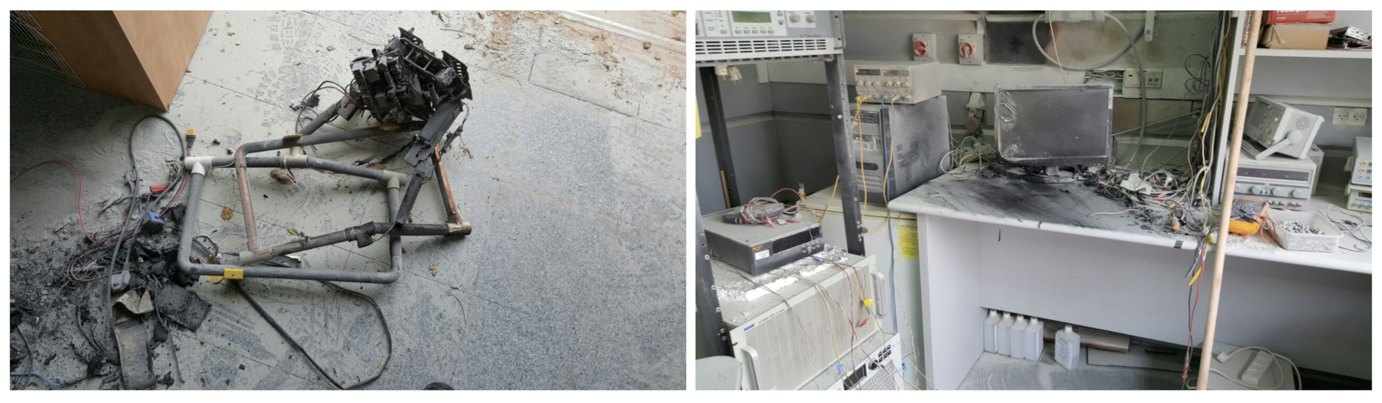
- Lithium batteries are explosive (e.g., see Figure 12), and dangerous situations can occur, so it was necessary to make sure all the experiments were performed in the proper settings. Figure 12 shows the result of a 1 kg lithium polymer battery explosion. During a lab charging (and discharging) experiment with the 24 V DC charger, one of the two 6S batteries overheated (most probably due to a manufacturing defect), and at some point, the defective battery exploded, causing a fire and a “total loss” of the drone and surrounding electronics. Due to safety regulations, there was no one near the faulty battery (the drone in the charging process), resulting in just minor damages to the gear and no harm to any person;
- Smart batteries with an inner protection (BMS) should be used [25,30]. This method can result in many lithium battery overheating or overcharging events, which may lead to battery explosions, as shown in Figure 12. We made sure that each battery had the following protection measures: (i) overcharge/overdischarge voltage cutoff; (ii) overheating: this was extremely important during charging experiments; (iii) maximum current;
- In a full field experiment, the generator should have a Residual-Current Device (RCD) that is both sensitive and has a fast cutoff (response) time (see Figure 13 for the basic field experiment setting).
5.2. Power Line Charging for Drones: Performance Evaluation
In order to evaluate the performance of the power line charging, we considered a relatively large drone with a minimum weight of 5 kg and a maximum weight of 10 kg; its flight time was 33–15 min accordingly. Such a (large) drone allowed us to install several parallel chargers and present the drone’s performance with respect to the number of onboard charges. Figure 3 (left) presents the charger’s settings in the drone; one can install 1–3 such chargers each with an expected charging rate of 200 W, allowing a maximal charging rate of 600 W. The flight experiments on the large drone were performed at an elevation of 2200–2300 ft (670–700 m) above sea level. The charging experiments were performed both in the field experiment and repeated for 10 charging and discharging cycles in the lab experiments. The results were relatively stable in all the experiments.
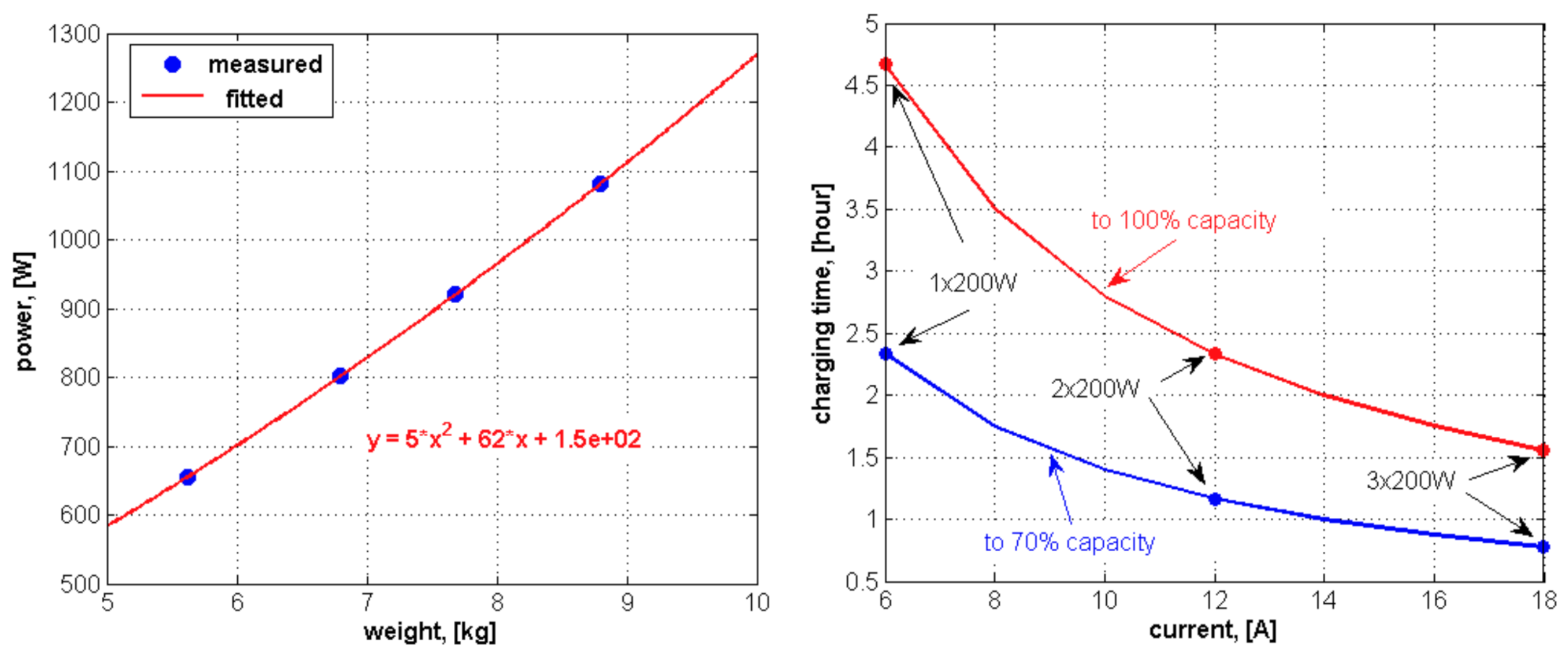
The correlation between the drone weight and its flight time is shown in Figure 14 (left); note that the graph is relatively “close” to linear. Figure 14 (right) presents the expected performance reduction with any additional charger. Overall, each charger reduced the flight time by about 4% of, which was considered acceptable. Figure 15 (left) presents the power consumption of the drone (Watts) with respect to its weight; again, one can see that the graph is relatively linear. Finally, in Figure 15 (right), the significant difference between charging the battery to 100% or to 70% is shown. The graph also presents the benefit of having all (three) chargers, allowing a speedy charge of about 45 min from 10% to 70% charge, which would allow a an extra flight time of about half an hour.
5.3. Power Line Landing Using Analog FPV Systems
The FPV is a popular method for controlling racing drones by human operators. Unlike LOS control in which the drone operator sees the drone and controls it accordingly, in the FPV, the operator sees what the drone cameras see and controls it accordingly. We found the FPV to be an efficient and safe method for controlling a drone while landing on power lines (or taking off from them). Combined with the “GPS position hold” mode, the FPV controlling method allowed us to test each of the three landing methods (vertical, rotation, hook) for over 50 successful landings on the power lines (without any “crashes”). Yet, the “hook landing” method was the fastest, allowing an experienced FPV operator to land the drone on a wire in less than 10 s (the same holds for the takeoff process). Moreover, the “hook landing” was performed on a single wire, allowing the robotic meter arm to reach the other wire in almost any configuration (as long as the wires were within 1 m apart), while for the other two methods (vertical and rotation), the distance between the two wires needed to fit the drone skids or “T-shaped” structures.
5.4. Two Drones’ Guided Autonomous Landing: Negative Results
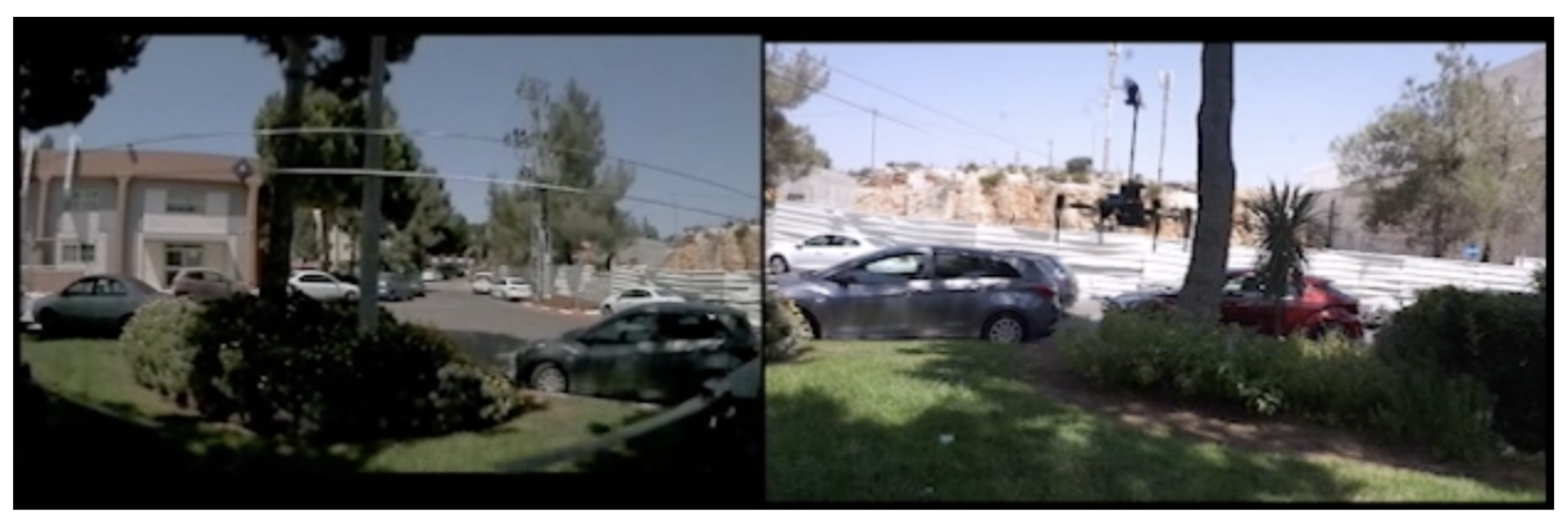
We found that in some cases, the onboard cameras could not always capture the whole picture. Therefore, we developed the following (complicated) guided landing method: (i) The first drone detected a landing spot and lands (or hovers) in a nearby location such that it could properly view the power lines in the landing position; (ii) then, the second drone approached the lines and was guided for “hook landing” by the operator based on the video as transmitted by the first drone; (iii) once the second drone has landed safely, the first drone may guide another drone for wire landing. After the first drone has completed the charging process, the first drone can also guide the takeoff stage of the second drone. Figure 16 presents the overall concept of guided landing (two drones). Note that both images (of Figure 16 are the actual view of the guiding drone, at a low resolution (360 P), as all the computations were performed “onboard” the guiding drone and needed to support at least 30 fps (preferably 60 fps).
5.5. Long-Range Power Line Landing
Recent improvements in long-range digital video transmitters such as DJI’s digital FPV system allow low-range and low-delay video transmutation: 4 km range, 28 ms delay (720P at 0 fps). We observed that in order to perform a safe FPV landing on the power lines, a delay of 100 ms was acceptable; therefore, one can use longer video transmission configurations, e.g., DJI’s OcuSync 3.0 has a range of up to 10 km (LOS conditions). Moreover, the “HereLink” digital video transmission system has a range of up to 20 km using a stack antenna. We were able to exceed this range by up to 25 km using a 14 dBi patch antenna. Finally, recent commercial drones such as Parrot’s Anafi AI have a built-in 4G (LTE) modem, allowing an operator to practically fly the drone at any range, as long as the drone has cellular coverage. Based on these advantages of long-range video transmission and due to safety regulations, we did not perform an autonomous landing on the power lines, limiting the landing to a human FPV operator. It should be noted that the expected video transmission range would often exceed the drone’s flying range. Yet, the challenge of autonomously and safely landing a drone on a power line is surely a research topic we will consider as a future work.
6. Conclusions and Future-Work
This paper focused on the concepts of charging drones (VTOLs) on power lines by landing on them, charging at a low voltage (100–250 V unisolated), and finally, taking off (safely) from the power lines. The main results of the paper were: (i) the concept of “hook landing”; (ii) the concept of a robotic meter arm. Combined, the two concepts allowed us to land on a single wire efficiently and safely; moreover, this allowed us to separate between the landing and the charging processes. The suggested method was implemented and tested on a few drone platforms. To the best of our knowledge, the charging performance of our suggested system on the Matrice 100 drone was outstanding, allowing a 1:1 ratio between charging and extra flight time. Landing a drone on a power line is risky, and there is a tendency to bury power lines [31]; however, the significant cost of such infrastructure improvements limits this tendency; thus, unisolated low-voltage power lines will probably remain common in a wide range of regions. We conjecture that in some cases, the use of a power-line-charging drone can in fact reduce the risk to firefighters and therefore might be considered. For future work, we plan to add an autonomous landing capability to the power-line-charging drone, the idea being to detect the wires (using vertical stereo cameras) and then performing a control algorithm according to the drone’s relative position to the wires. Finally, we plan to design a safe charging station, which will use 24 V DC wires and allow a set of commercial drones to perform a safe and efficient charging.
Funding
This research was partly supported by: The Israel Ministry of Defence - Directorate of Defence Research & Development (IMOD, MAFAT).
Institutional Review Board Statement
Not applicable.
Informed Consent Statement
Not applicable.
Data Availability Statement
None.
Acknowledgments
The author would like to thank Kfir Cohem, Kobi Gozlan, Amit Kashi, and Itiel Rosenberg for constructing the various charging drones and performing the experiments. The author would also like to thank Alon Kuperman and Moshe Setboin for helping to analyze the charging performance of the drones and introducing me to the world of charging optimisation.
Conflicts of Interest
The author declares no conflict of interest.
References
- Boukoberine, M.N.; Zhou, Z.; Benbouzid, M. A critical review on unmanned aerial vehicles power supply and energy management: Solutions, strategies, and prospects. Appl. Energy 2019, 255, 113823. [Google Scholar] [CrossRef]
- Sărăcin, C.G.; Dragoş, I.; Chirilă, A.I. Powering aerial surveillance drones. In Proceedings of the 2017 10th International Symposium on Advanced Topics in Electrical Engineering (ATEE), Bucharest, Romania, 23–25 March 2017; pp. 237–240. [Google Scholar]
- Sato, S.; Anezaki, T. Autonomous flight drone for infrastructure (transmission line) inspection (2). In Proceedings of the 2017 International Conference on Intelligent Informatics and Biomedical Sciences (ICIIBMS), Okinawa, Japan, 24–26 November 2017; pp. 294–296. [Google Scholar]
- Besada, J.A.; Bergesio, L.; Campaña, I.; Vaquero-Melchor, D.; López-Araquistain, J.; Bernardos, A.M.; Casar, J.R. Drone mission definition and implementation for automated infrastructure inspection using airborne sensors. Sensors 2018, 18, 1170. [Google Scholar] [CrossRef] [PubMed] [Green Version]
- Zhou, G.; Yuan, J.; Yen, I.L.; Bastani, F. Robust real-time UAV based power line detection and tracking. In Proceedings of the 2016 IEEE International Conference on Image Processing (ICIP), Phoenix, AZ, USA, 25–28 September 2016; pp. 744–748. [Google Scholar]
- Dihkan, M.; Mus, E. Automatic detection of power transmission lines and risky object locations using UAV LiDAR data. Arab. J. Geosci. 2021, 14, 1–13. [Google Scholar] [CrossRef]
- Lu, M.; Bagheri, M.; James, A.P.; Phung, T. Wireless charging techniques for UAVs: A review, reconceptualization, and extension. IEEE Access 2018, 6, 29865–29884. [Google Scholar] [CrossRef]
- Lu, M.; James, A.; Bagheri, M. Unmanned Aerial Vehicle (UAV) charging from powerlines. In Proceedings of the 2017 IEEE PES Asia-Pacific Power and Energy Engineering Conference (APPEEC), Bangalore, India, 8–10 November 2017; pp. 1–6. [Google Scholar]
- Campi, T.; Cruciani, S.; Maradei, F.; Feliziani, M. Wireless charging system integrated in a small unmanned aerial vehicle (UAV) with high tolerance to planar coil misalignment. In Proceedings of the 2019 Joint International Symposium on Electromagnetic Compatibility, Sapporo and Asia-Pacific International Symposium on Electromagnetic Compatibility (EMC Sapporo/APEMC), Sapporo, Japan, 3–7 June 2019; pp. 601–604. [Google Scholar]
- Galkin, B.; Kibilda, J.; DaSilva, L.A. UAVs as mobile infrastructure: Addressing battery lifetime. IEEE Commun. Mag. 2019, 57, 132–137. [Google Scholar] [CrossRef] [Green Version]
- Choi, C.H.; Jang, H.J.; Lim, S.G.; Lim, H.C.; Cho, S.H.; Gaponov, I. Automatic wireless drone charging station creating essential environment for continuous drone operation. In Proceedings of the 2016 International Conference on Control, Automation and Information Sciences (ICCAIS), Ansan, Korea, 27–29 October 2016; pp. 132–136. [Google Scholar]
- Rohan, A.; Rabah, M.; Asghar, F.; Talha, M.; Kim, S.H. Advanced drone battery charging system. J. Electr. Eng. Technol. 2019, 14, 1395–1405. [Google Scholar] [CrossRef]
- Skycharge: High Power Drone Charging Pad and Infrastructure. Available online: https://skycharge.de/ (accessed on 20 August 2021).
- Heisha DNEST: Drone in the Box. Available online: https://www.heishatech.com/ (accessed on 20 August 2021).
- Flytbase. Available online: https://flytbase.com/ (accessed on 20 August 2021).
- Fujii, K.; Higuchi, K.; Rekimoto, J. Endless flyer: A continuous flying drone with automatic battery replacement. In Proceedings of the 2013 IEEE 10th International Conference on Ubiquitous Intelligence and Computing and 2013 IEEE 10th International Conference on Autonomic And Trusted Computing, Vietri sul Mare, Italy, 18–21 December 2013; pp. 216–223. [Google Scholar]
- Lee, D.; Zhou, J.; Lin, W.T. Autonomous battery swapping system for quadcopter. In Proceedings of the 2015 International Conference on Unmanned Aircraft Systems (ICUAS), Denver, CO, USA, 9–12 June 2015; pp. 118–124. [Google Scholar]
- Shavarani, S.M.; Nejad, M.G.; Rismanchian, F.; Izbirak, G. Application of hierarchical facility location problem for optimization of a drone delivery system: A case study of Amazon prime air in the city of San Francisco. Int. J. Adv. Manuf. Technol. 2018, 95, 3141–3153. [Google Scholar] [CrossRef]
- Dorling, K.; Heinrichs, J.; Messier, G.G.; Magierowski, S. Vehicle routing problems for drone delivery. IEEE Trans. Syst. Man Cybern. Syst. 2016, 47, 70–85. [Google Scholar] [CrossRef] [Green Version]
- Hong, I.; Kuby, M.; Murray, A.T. A range-restricted recharging station coverage model for drone delivery service planning. Transp. Res. Part C Emerg. Technol. 2018, 90, 198–212. [Google Scholar] [CrossRef]
- Huang, H.; Savkin, A.V. A method of optimized deployment of charging stations for drone delivery. IEEE Trans. Transp. Electrif. 2020, 6, 510–518. [Google Scholar] [CrossRef]
- Cokyasar, T. Optimization of battery swapping infrastructure for e-commerce drone delivery. Comput. Commun. 2021, 168, 146–154. [Google Scholar] [CrossRef]
- Shaheed, M.H.; Abidali, A.; Ahmed, J.; Ahmed, S.; Burba, I.; Fani, P.J.; Kwofie, G.; Wojewoda, K.; Munjiza, A. Flying by the Sun only: The Solarcopter prototype. Aerosp. Sci. Technol. 2015, 45, 209–214. [Google Scholar] [CrossRef]
- Oettershagen, P.; Melzer, A.; Mantel, T.; Rudin, K.; Stastny, T.; Wawrzacz, B.; Hinzmann, T.; Alexis, K.; Siegwart, R. Perpetual flight with a small solar-powered UAV: Flight results, performance analysis and model validation. In Proceedings of the 2016 IEEE Aerospace Conference, Big Sky, MT, USA, 5–12 March 2016; pp. 1–8. [Google Scholar]
- Chittoor, P.K.; Chokkalingam, B.; Mihet-Popa, L. A Review on UAV Wireless Charging: Fundamentals, Applications, Charging Techniques and Standards. IEEE Access 2021, 9, 69235–69266. [Google Scholar] [CrossRef]
- Tang, L.; Shao, G. Drone remote sensing for forestry research and practices. J. For. Res. 2015, 26, 791–797. [Google Scholar] [CrossRef]
- Viseras, A.; Marchal, J.; Schaab, M.; Pages, J.; Estivill, L. Wildfire Monitoring and Hotspots Detection with Aerial Robots: Measurement Campaign and First Results. In Proceedings of the 2019 IEEE International Symposium on Safety, Security, and Rescue Robotics (SSRR), Würzburg, Germany, 2–4 September 2019; pp. 102–103. [Google Scholar]
- Samiappan, S.; Hathcock, L.; Turnage, G.; McCraine, C.; Pitchford, J.; Moorhead, R. Remote sensing of wildfire using a small unmanned aerial system: Post-fire mapping, vegetation recovery and damage analysis in Grand Bay, Mississippi/Alabama, USA. Drones 2019, 3, 43. [Google Scholar] [CrossRef] [Green Version]
- Nguyen, M.T.; Nguyen, C.V.; Truong, L.H.; Le, A.M.; Quyen, T.V.; Masaracchia, A.; Teague, K.A. Electromagnetic field based wpt technologies for uavs: A comprehensive survey. Electronics 2020, 9, 461. [Google Scholar] [CrossRef] [Green Version]
- Carkhuff, B.G.; Demirev, P.A.; Srinivasan, R. Impedance-based battery management system for safety monitoring of lithium-ion batteries. IEEE Trans. Ind. Electron. 2018, 65, 6497–6504. [Google Scholar] [CrossRef]
- Bizjak, T.; Bollag, S.; Kasler, D. Power lines keep sparking wildfires. Why don’t California utility companies bury them? Sacbee, 16 November 2018. [Google Scholar]
Figure 1.
The power-line-charging drone concept: (Left) DJI’s Matrice 100 with all the additional mechanisms that allow it to safely land on a wire and charge from the power line (100–250 V). (Mid) The wire landing gear and robotic meter. (Right) Actual charging of 196 Watt -as measured by the onboard current sensor.
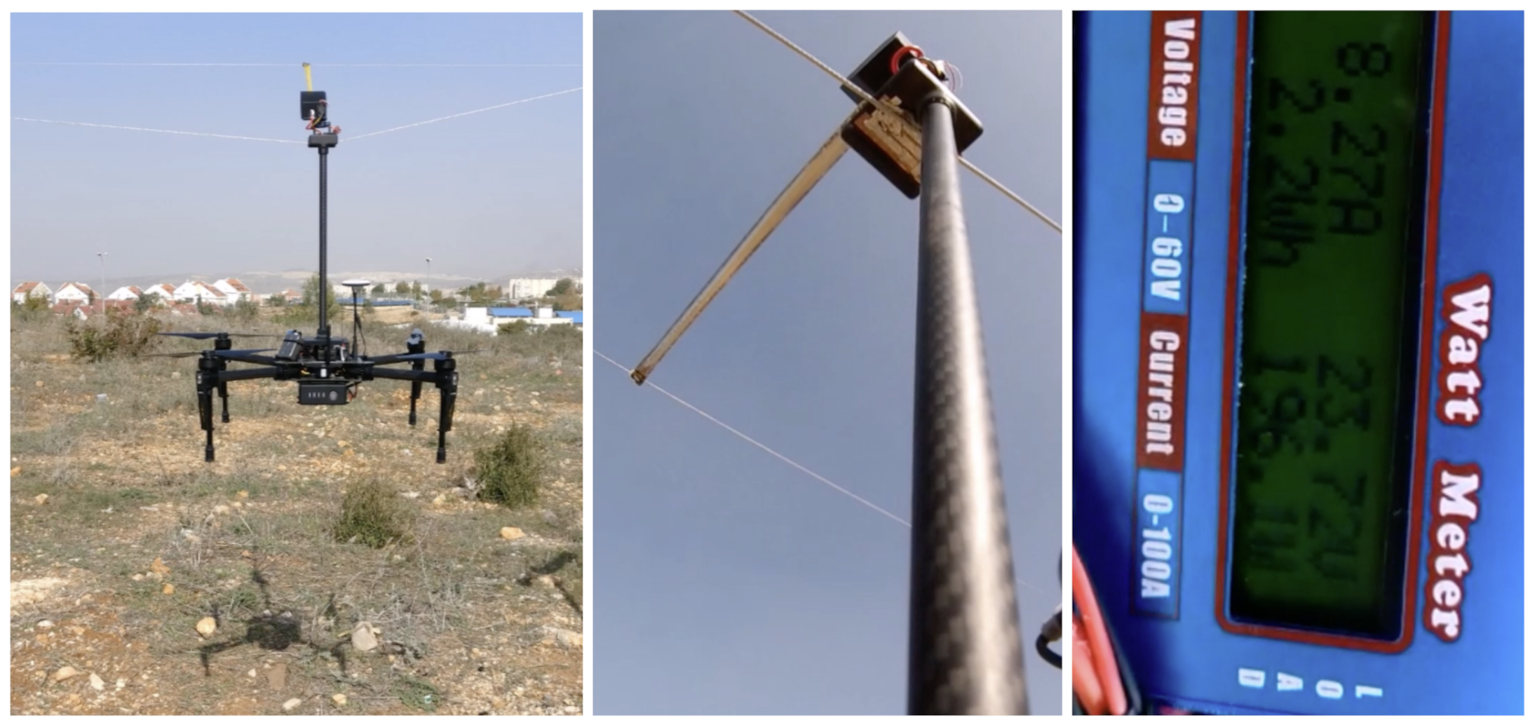
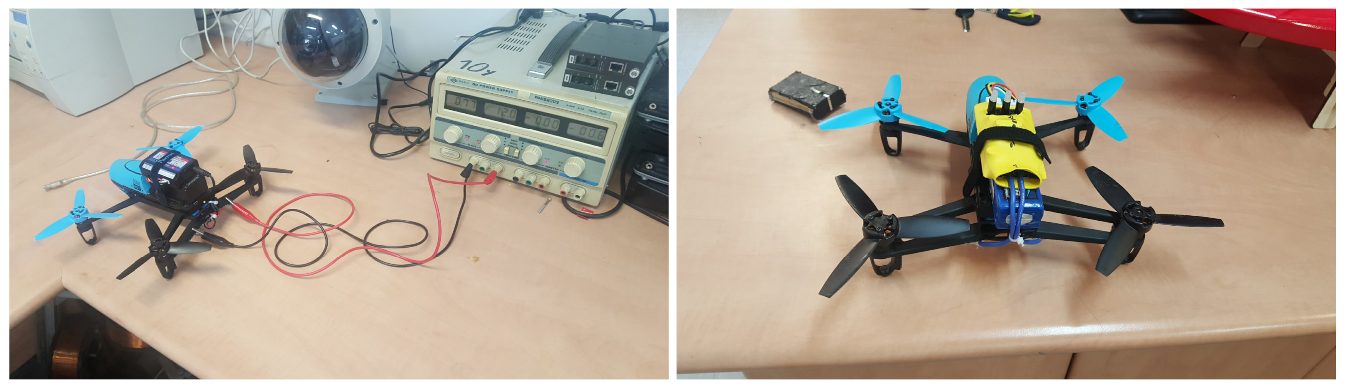
Figure 2.
The very basic concepts of the drone with the onboard charger. (Left) Parrot Beebop 1.0 with a standard 3S battery and a 12 V charger connected to it. The drone is charged from a 12 V (DC) power source. (Right) The same drone with two conductive plates on its back legs—ready for basic testing—with an additional weight of about 50 g added to the drone.

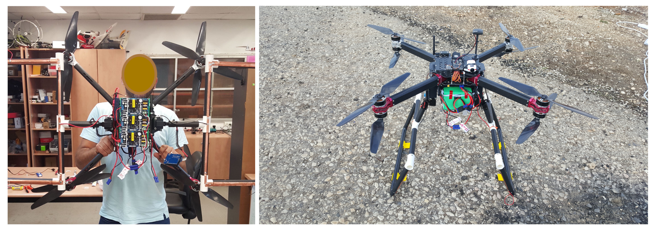
Figure 3.
The vertical landing drone. (Left) The drone as seen from “below”, showing three parallel chargers and the skids in open position (with the conductive strips and the needed wiring to and from the chargers). (Right) The vertical landing drone in a “standing position”, ready to fly. The drone has 8 motors (2 on each arm), a weight of 5 kg, another 0.25–0.75 kg of onboard chargers, and the ability to lift another 4 kg of payload or batteries—a total maximum of 10 kg.

Figure 4.
Vertical landing and charging.

Figure 5.
Vertical landing requires parallel, leveled, and horizontal wires, which is often not the case for real-world power lines.
Figure 5.
Vertical landing requires parallel, leveled, and horizontal wires, which is often not the case for real-world power lines.
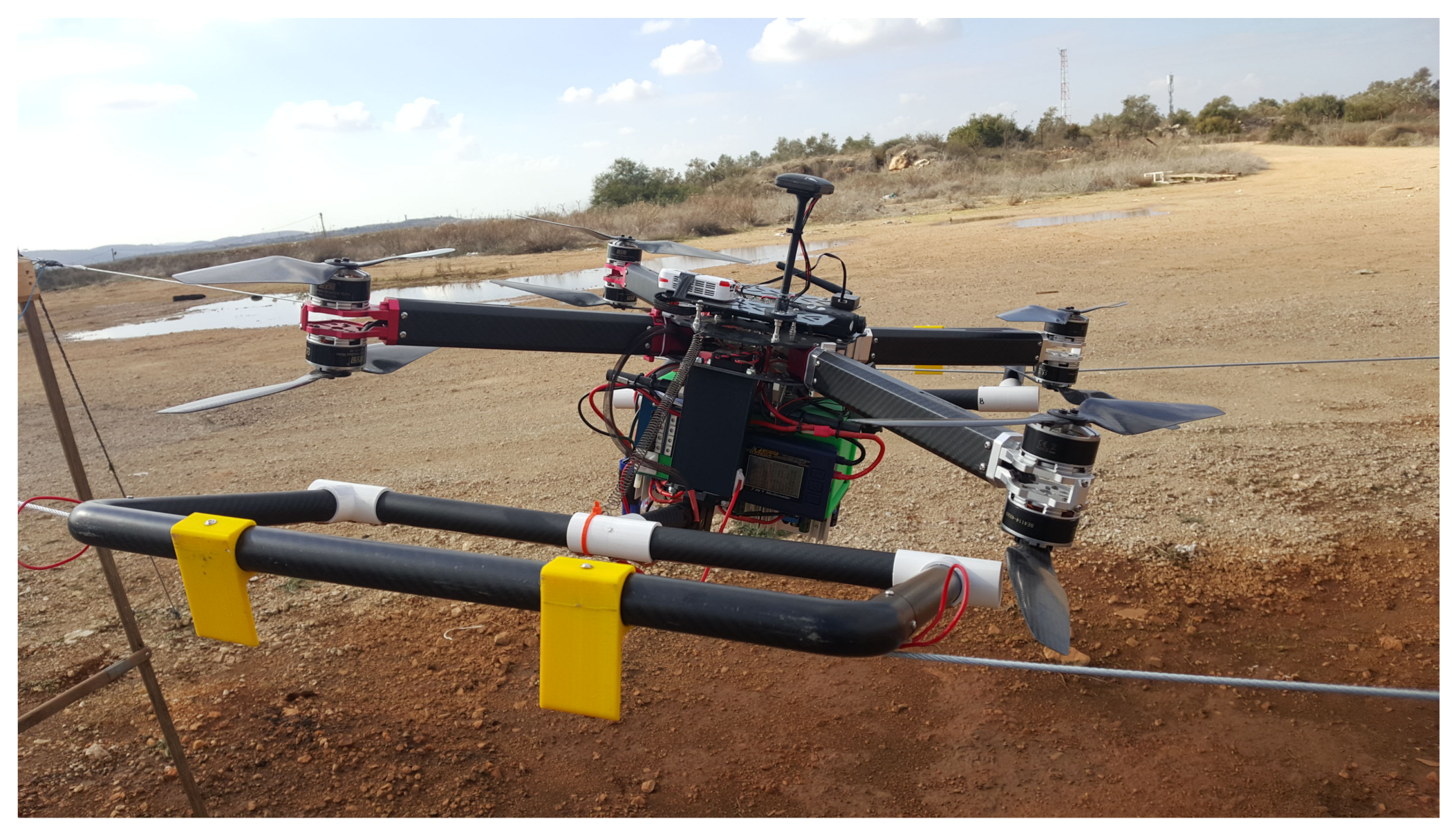
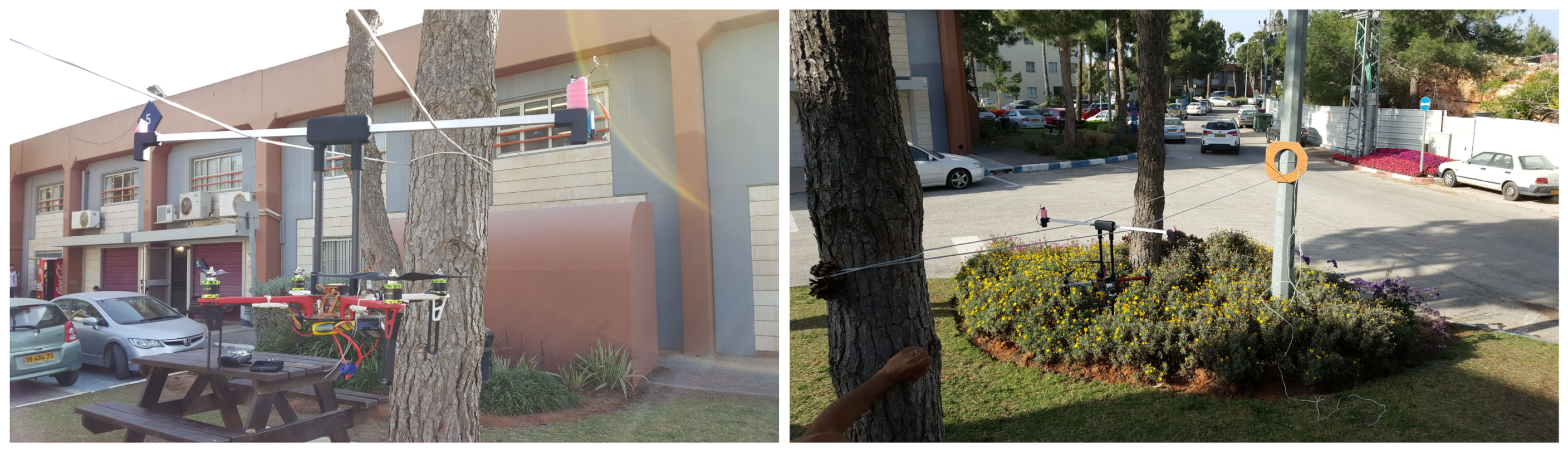
Figure 6.
Rotation landing: the drone approaches the wires from underneath, and the “T-shaped” structure is aligned with the two wires (in between the wires). (Left) The drone’s FPV camera is located on one of the sides of the “T-shaped” structure (marked in pink). (Right) The experiment setting: a very basic structure to practice FPV-based “rotation landing”.

Figure 7.
Hook drone: DJI’s Matrice 100 with an additional vertical pole with a hook and a robotic meter. (Left) A view from above. (Right) Hook landing: indoor experiment. The drone simply flies below the wire while the hook is above it, and when the drone touches the wire, it reduces the throttle, allowing it to land on the wire.
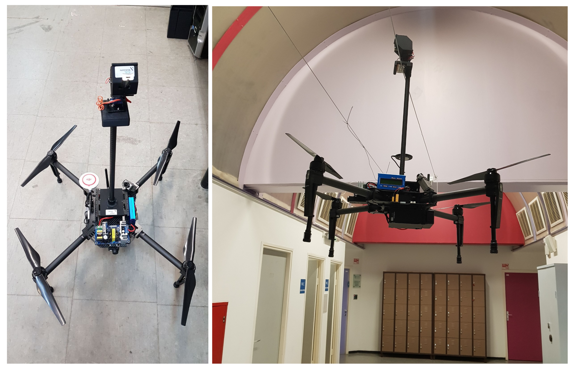
Figure 8.
Takeoff from a wire: the reverse order of landing. The drone starts the motors, elevates its hook above the wire, and then, flies back until it is at a safe distance from the wires.
Figure 8.
Takeoff from a wire: the reverse order of landing. The drone starts the motors, elevates its hook above the wire, and then, flies back until it is at a safe distance from the wires.

Figure 9.
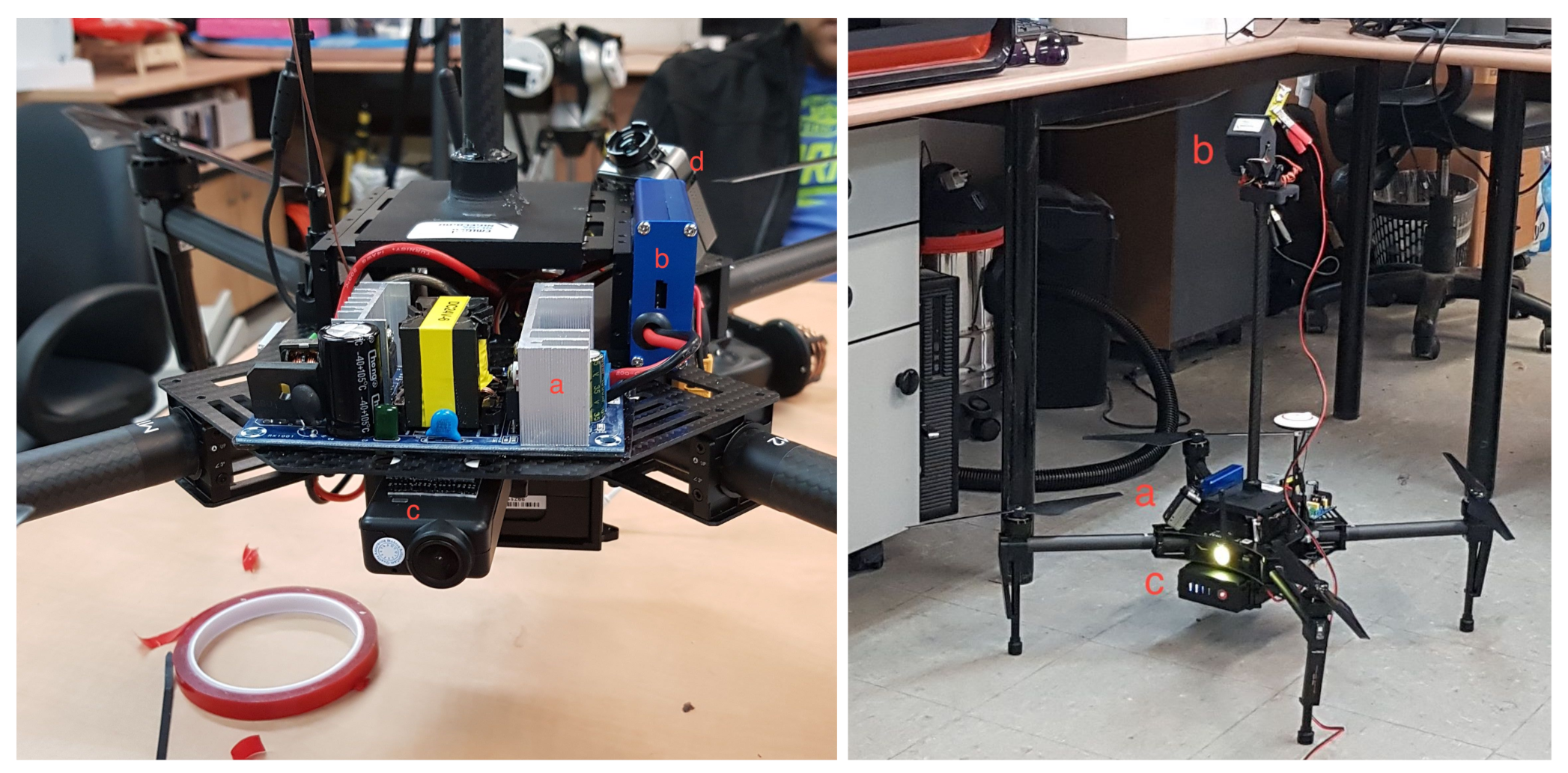
The advanced power-line-charging drone, equipped with a pole containing a hook and a robotic meter above it. (Left) The main components added to the drone: (a) Charger: converter for 100–250 V AC to 24 V DC, up to 12Amp. (b) The current meter allowed us to see the actual charging rate and the energy capacity added to the battery. (c) The wide-angle front camera. (d) The wide-angle up camera, allowing the operator to position the hook of the drone on the wire and then operate the robotic meter to the other wire. (Right) The basic charging experiment: (a) For safety reasons, performed on 24 V DC. (b) The drone’s original power charger was connected (via wires) to the hook and the end of the meter. (c) The drone was both working (armed) and being charged.
Figure 9.
The advanced power-line-charging drone, equipped with a pole containing a hook and a robotic meter above it. (Left) The main components added to the drone: (a) Charger: converter for 100–250 V AC to 24 V DC, up to 12Amp. (b) The current meter allowed us to see the actual charging rate and the energy capacity added to the battery. (c) The wide-angle front camera. (d) The wide-angle up camera, allowing the operator to position the hook of the drone on the wire and then operate the robotic meter to the other wire. (Right) The basic charging experiment: (a) For safety reasons, performed on 24 V DC. (b) The drone’s original power charger was connected (via wires) to the hook and the end of the meter. (c) The drone was both working (armed) and being charged.

Figure 10.
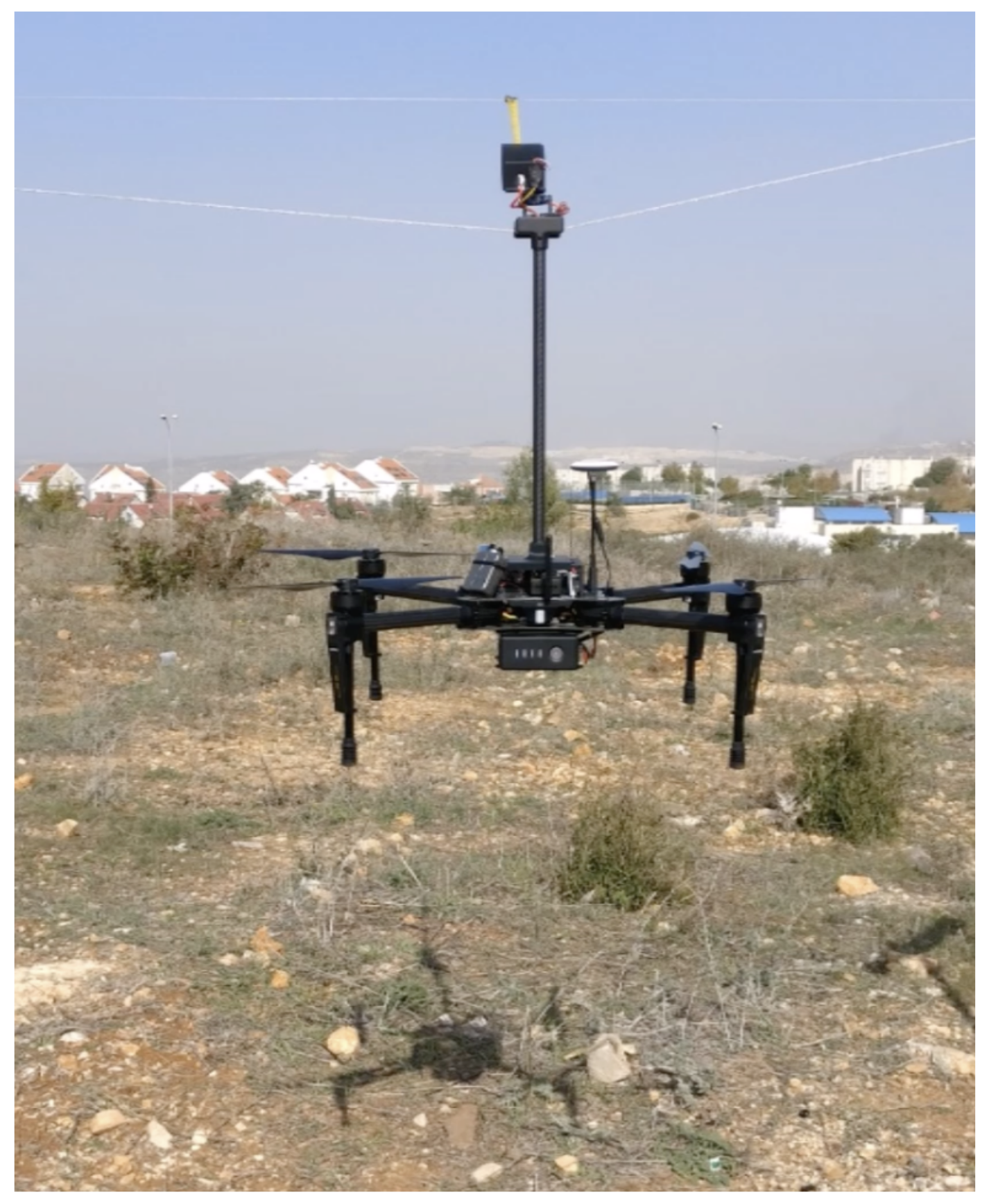
Hook landing: testing the ability to guide the robotic meter to the other wire. The image was taken from a real charging experiment using a 220 V AC generator. Note that the first wire (to which the hook was connected) was lower than the second one; this was not an issue as the robotic meter had a “pitch” range of 145.
Figure 10.
Hook landing: testing the ability to guide the robotic meter to the other wire. The image was taken from a real charging experiment using a 220 V AC generator. Note that the first wire (to which the hook was connected) was lower than the second one; this was not an issue as the robotic meter had a “pitch” range of 145.

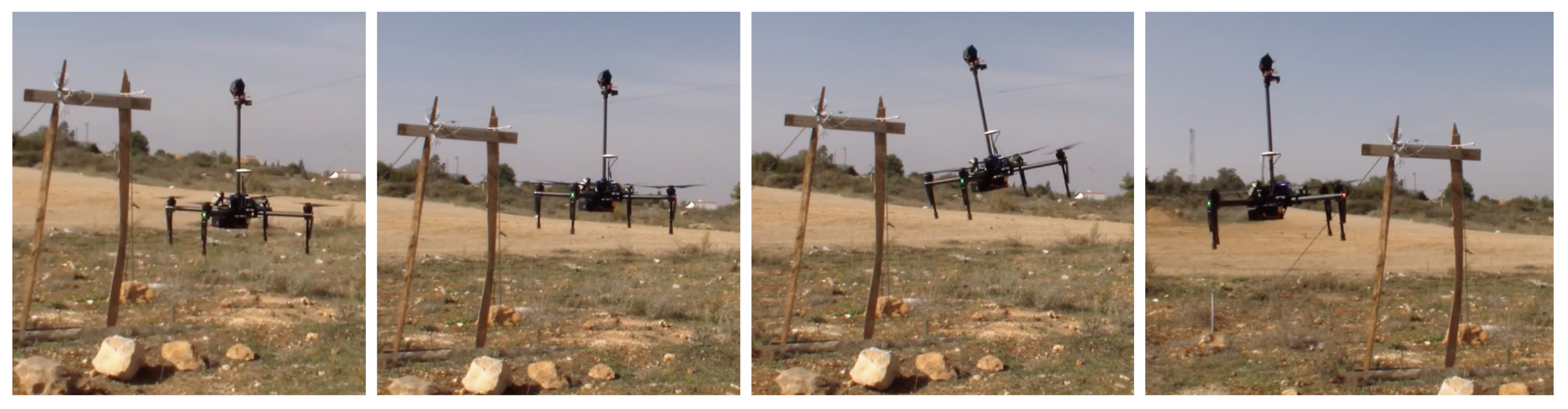
Figure 11.
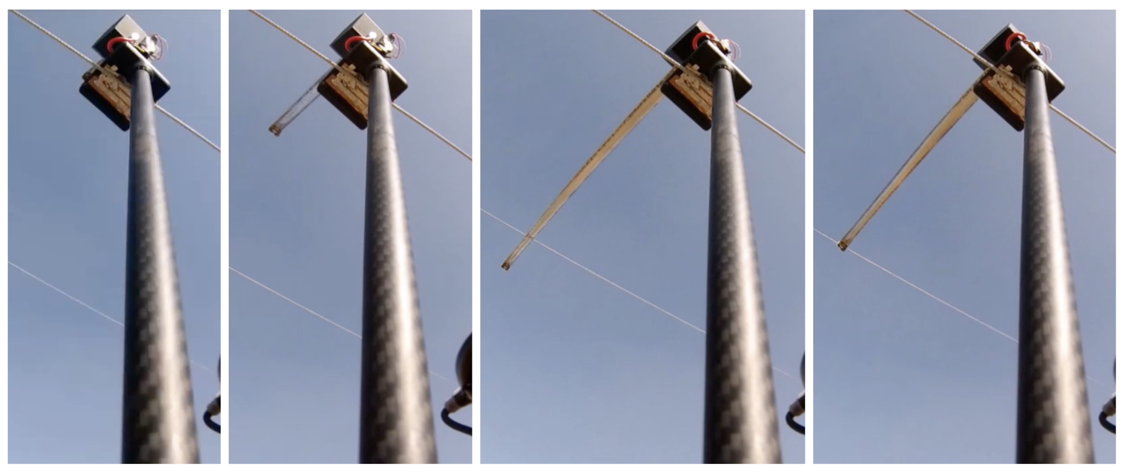
The robotic meter arm in action. (Left to Right) The drone lands on the first wire (the meter is closed). The robotic meter starts to open, in the general direction of the second wire (aiming above it). The meter passes above the second wire and then drops onto it. Finally, the meter draws back until it connects tightly to the second wire.
Figure 11.
The robotic meter arm in action. (Left to Right) The drone lands on the first wire (the meter is closed). The robotic meter starts to open, in the general direction of the second wire (aiming above it). The meter passes above the second wire and then drops onto it. Finally, the meter draws back until it connects tightly to the second wire.

Figure 12.
The result of a 1kg lithium polymer battery explosion. (Left) The remains of the drone after the explosion. (Right) The result of the burning and the extreme heat caused by the battery explosion.
Figure 12.
The result of a 1kg lithium polymer battery explosion. (Left) The remains of the drone after the explosion. (Right) The result of the burning and the extreme heat caused by the battery explosion.

Figure 13.
The basic experimental setting, which included a power line demo structure with two parallel wires. (Left) The low-power (safe, 24 V DC) settings. (Right) The real-world experiment using a 220 V generator with an extra safety Residual-Current Device (RCD) that was both sensitive and had a fast cutoff (response) time.
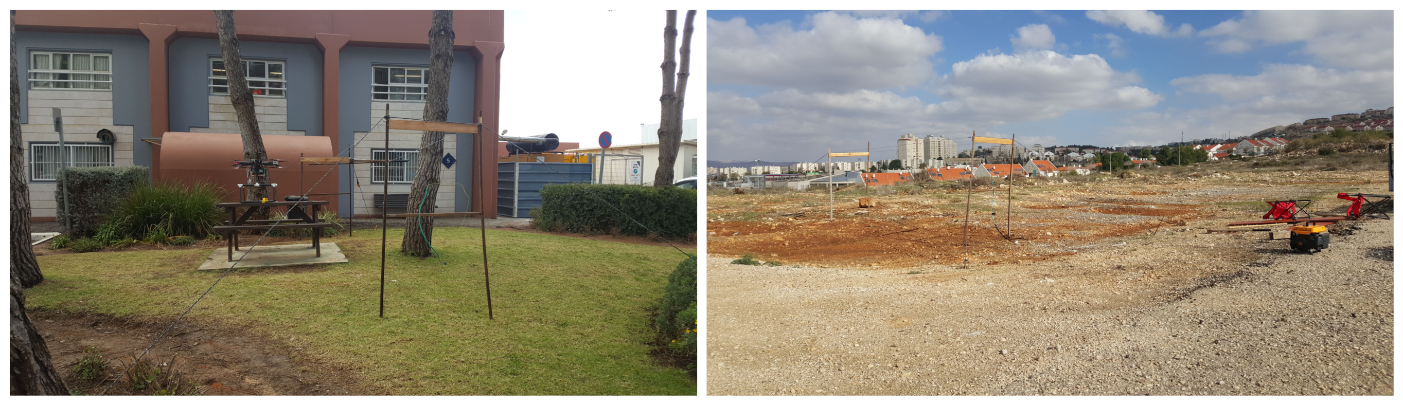
Figure 14.
The relation between the drone weight and its flight time. (Left) The graph of the original drone without any onboard chargers. (Right) The graph for each onboard charger configuration (0–3).
Figure 14.
The relation between the drone weight and its flight time. (Left) The graph of the original drone without any onboard chargers. (Right) The graph for each onboard charger configuration (0–3).

Figure 15.
Discharge and charging rates. (Left) The measured energy consumption of the drone with respect to its weight. (Right) Charging time, using 1–3 chargers; the red line represents the time until being fully (100%) charged, while the blue line presents the time for a 70% charge.
Figure 15.
Discharge and charging rates. (Left) The measured energy consumption of the drone with respect to its weight. (Right) Charging time, using 1–3 chargers; the red line represents the time until being fully (100%) charged, while the blue line presents the time for a 70% charge.

Figure 16.
Guided landing: for this, two drones are needed: (Left) The first drone detects possible power lines. (Right) The first drone guides the second one to the power lines until it lands on the first wire. Finally, the second drone can guide the first one to land nearby it (on the same power lines).

Publisher’s Note: MDPI stays neutral with regard to jurisdictional claims in published maps and institutional affiliations. |
© 2021 by the author. Licensee MDPI, Basel, Switzerland. This article is an open access article distributed under the terms and conditions of the Creative Commons Attribution (CC BY) license (https://creativecommons.org/licenses/by/4.0/).
Share and Cite
MDPI and ACS Style
Ben-Moshe, B. Power Line Charging Mechanism for Drones. Drones 2021, 5, 108. https://doi.org/10.3390/drones5040108
AMA Style
Ben-Moshe B. Power Line Charging Mechanism for Drones. Drones. 2021; 5(4):108. https://doi.org/10.3390/drones5040108
Chicago/Turabian StyleBen-Moshe, Boaz. 2021. "Power Line Charging Mechanism for Drones" Drones 5, no. 4: 108. https://doi.org/10.3390/drones5040108
APA StyleBen-Moshe, B. (2021). Power Line Charging Mechanism for Drones. Drones, 5(4), 108. https://doi.org/10.3390/drones5040108