1. Introduction
Unmanned aerial vehicles (UAVs) are increasingly utilised in inspection, logistics, agriculture, environmental monitoring, surveillance, and other safety-critical missions [
1,
2,
3]. As missions become more important, ensuring structural reliability and integrity becomes essential to maintain flight safety and mission continuity [
4,
5,
6]. In parallel, deep learning-based solutions have also been developed for UAV ground infrastructure, including thermal helipad detection systems that enhance autonomous landing capabilities [
7]. Failures in rotor-propulsion assemblies, sensors, and structural components may lead to degraded flight performance or catastrophic system loss [
8,
9,
10,
11]. As a result, fault detection, anomaly diagnosis, and remaining useful life (RUL) prediction have become central topics in UAV health management. Recent reviews of UAV fault detection and AI-driven anomaly analysis document the transition from classical control-based diagnostics to data-driven intelligent monitoring frameworks [
12,
13,
14]. Despite significant advancements, a persistent challenge remains the limited availability of representative degraded datasets, particularly concerning vibration-induced structural and propulsion faults.
A substantial body of UAV fault diagnosis research focuses on control-level and component-specific anomalies. Vibration-informed quadcopter fault detection has been studied using residual-based methods [
15], while actuator damage diagnosis has been addressed through stacked machine learning models [
16]. Sensor faults under limited labeled data have been tackled via multi-auxiliary task learning [
17], and collaborative feature-sharing strategies have been proposed to enhance cross-condition robustness [
18]. Digital twin frameworks have also been introduced to improve control fidelity under complex loading conditions [
19]. Although these approaches enhance control reliability and anomaly awareness, they primarily address discrete faults and do not explicitly capture progressive mechanical degradation in rotor–propulsion systems.
Rotor imbalance is among the most prevalent and safety-relevant degradation mechanisms in rotary-wing UAVs. Progressive imbalance may arise from material loss, blade surface damage, adhesive contamination, or minor impacts, leading to centrifugal force asymmetry [
20,
21,
22]. From a rotor dynamics perspective, imbalance growth induces systematic amplification of vibration energy near the rotational fundamental and its harmonics, accompanied by subtle frequency variations under changing aerodynamic loading. If undetected, imbalance can propagate into increased bearing loads, structural fatigue, and eventual in-flight instability [
23,
24,
25]. Therefore, early-stage imbalance detection is not merely a diagnostic problem but a safety-critical requirement.
Vibration-based structural health monitoring (SHM) has received growing research interest in this context. Experimental characterization of UAV structural vibration under controlled engine tests has established baseline dynamic behavior [
26]. Time–frequency feature extraction methods, such as wavelet scattering, have been applied to quadcopter SHM [
27]. Propeller imbalance detection has been investigated using thrust-dependent FFT-based diagnostics [
28], feature ranking-enhanced machine learning [
29], and sensitivity analysis of vibration direction and kernel selection [
30]. System-level vibration monitoring with Micro-Electro-Mechanical Systems (MEMS) sensors has been proposed for propeller and structural faults [
31], and lifecycle-integrated vibration-based SHM architectures have been developed [
32]. Deep learning methods have also been applied to improve feature extraction for UAV vibration anomaly detection [
33]. In related structural domains, active vibration control methods incorporating piezoelectric actuation and nonlinear modeling have advanced suppression strategies for flexible cable structures [
34], while time-delay measurement and decoupling compensation techniques have improved vibration control of flexible beam systems under multi-modal excitation [
35]. In addition, AI-based anomaly detection techniques have been applied to structural fault diagnosis using low-sampling-rate vibration data in rotorcraft systems [
36], and investigations into data anomaly detection challenges using deep-learning and rule-based classifications have provided critical insights for long-term vibration monitoring applications [
37]. Despite these advances, most existing studies rely on experimentally induced faults at discrete severity levels, implicitly assuming that the measured dataset sufficiently represents the degradation space encountered in real operation.
Acoustic diagnostics provide complementary insight into propeller damage [
38,
39], and uncertainty-aware acoustic augmentation strategies have been explored [
40]. However, acoustic signals are susceptible to environmental interference and may not directly capture internal rotor–structure interaction dynamics as effectively as vibration measurements.
Deep learning architectures have expanded UAV anomaly detection capabilities, including autoencoder-based unsupervised detection [
41,
42,
43], clustering-based failure detection [
44], blade damage diagnosis using deep neural networks [
45,
46], proactive fault detection for quadrotor safety [
47], and metric learning for unknown anomaly detection [
48]. Advanced neural structures such as hypergraph wavelet networks further improve multi-scale fault representation [
49]. Cross-system anomaly detection frameworks based on coupled feature learning have shown that autoencoder architectures can identify faults propagating across interconnected subsystems [
50]. Comparative evaluations of unsupervised deep learning methods for anomaly detection in flight data have also indicated the advantages of temporal architectures in capturing long-range dependencies in operational sequences [
51]. Nevertheless, even sophisticated architectures remain fundamentally dependent on the statistical diversity of training data. When trained on limited discrete imbalance severities, deep models tend to learn classification boundaries rather than continuous degradation trends. This limitation becomes critical in early-stage imbalance detection, where degradation evolves gradually and may remain within the statistical envelope of nominal variability.
Cross-domain predictive maintenance studies support this point: deep temporal models for vibration anomaly detection in industrial machinery depend on representative degradation variability [
52], and unsupervised defect detection in manufacturing signals similarly highlights the need for physically meaningful data coverage [
53]. Sequential multi-objective reinforcement learning approaches have also shown the value of intelligent maintenance scheduling in complex propulsion systems such as turbofan engines [
54]. Hybrid analytical-to-AI frameworks show that embedding physical structure into learning pipelines improves model accuracy and interpretability [
55], consistent with broader trends in domain-knowledge-guided learning [
56]. These findings suggest that combining domain physics with data-driven modeling can enhance generalization in safety-critical systems [
57,
58,
59].
Despite extensive research in UAV vibration diagnostics and deep learning-based anomaly detection, three fundamental limitations persist in the literature: (i) reliance on a limited range of fault states with restricted degradation diversity; (ii) the absence of a framework that explicitly synthesises imbalance states while incorporating frequency drift; and (iii) inadequate integration of mechanical degradation physics into deep learning training pipelines.
To address this limitation, the present study proposes a severity-ordered augmented vibration data framework for UAV anomaly detection. The approach explicitly models rotor imbalance growth by incorporating centrifugal-force-driven harmonic amplification and throttle-conditioned frequency drift into the augmentation process. Rather than relying solely on discrete measured fault states, the method generates physically interpretable intermediate degradation levels, which expand the degradation manifold presented to the deep learning model. The main contributions of this study are summarized as follows:
A multi-condition experimental dataset acquired under 23 distinct propeller conditions (healthy, tape-induced imbalance at 5/10/15 layers, scratch faults at 25/50/75% depth, and complete cuts at three radial locations), each repeated three times under stepped throttle excitation from 10% to 100%.
A severity-ordered vibration data augmentation framework that reconstructs a continuous degradation trajectory from discrete experimental fault states by ordering segments according to a peak-to-peak severity metric and throttle level, yielding approximately 7.5 h of augmented vibration data per axis.
Explicit incorporation of frequency drift behavior under throttle-conditioned operation, enabling the model to capture rotor-speed-dependent spectral variations associated with progressive imbalance growth.
Integration of the proposed augmentation into an unsupervised anomaly detection framework based on a hybrid CNN–BiGRU–SSM–AE architecture, combining convolutional time–frequency encoding, bidirectional temporal modeling, and state-space dynamics with throttle-aware conditioning.
Experimental validation showing that the proposed framework achieves a precision of 0.9959, a recall of 0.4428, an F1-score of 0.6131, and an AUROC of 0.9284, outperforming Isolation Forest, One-Class SVM, and LSTM–AE baselines in early-stage imbalance sensitivity and generalization.
The remainder of this paper is organized as follows:
Section 2 explains the material and methods, including data collection and the details of the CWT-CNN models used in the study.
Section 3 presents the experimental results and the performance of the proposed model. Finally,
Section 4 summarizes the main conclusions and highlights the limitations of the study.
2. Materials and Methods
2.1. Experimental Details
The experimental campaign was designed to acquire high-fidelity vibration responses from a rotary-wing UAV propulsion system by systematically introducing physical propeller anomalies under controlled and repeatable operating conditions. The primary vibration measurements were acquired using Analog Devices ADXL345 accelerometers (Analog Devices, Inc., Wilmington, MA, USA; ±16 g range, 3.9 mg/LSB resolution), sampled at 800 Hz via a 400 kHz I
2C interface. One accelerometer was mounted directly on the centre of gravity of the UAV to capture structural propagation effects across the airframe. This center-of-gravity placement mimics a minimalist, cost-effective structural health monitoring framework. It successfully captures the global airframe transmission of propulsion vibrations coupled with structural modes, representing a highly realistic operational scenario for small UAVs where distributed multi-sensor arrays are constrained by strict payload limitations. The accelerometer measurement axes are aligned with the standard UAV body-fixed coordinate system, where the
X,
Y, and
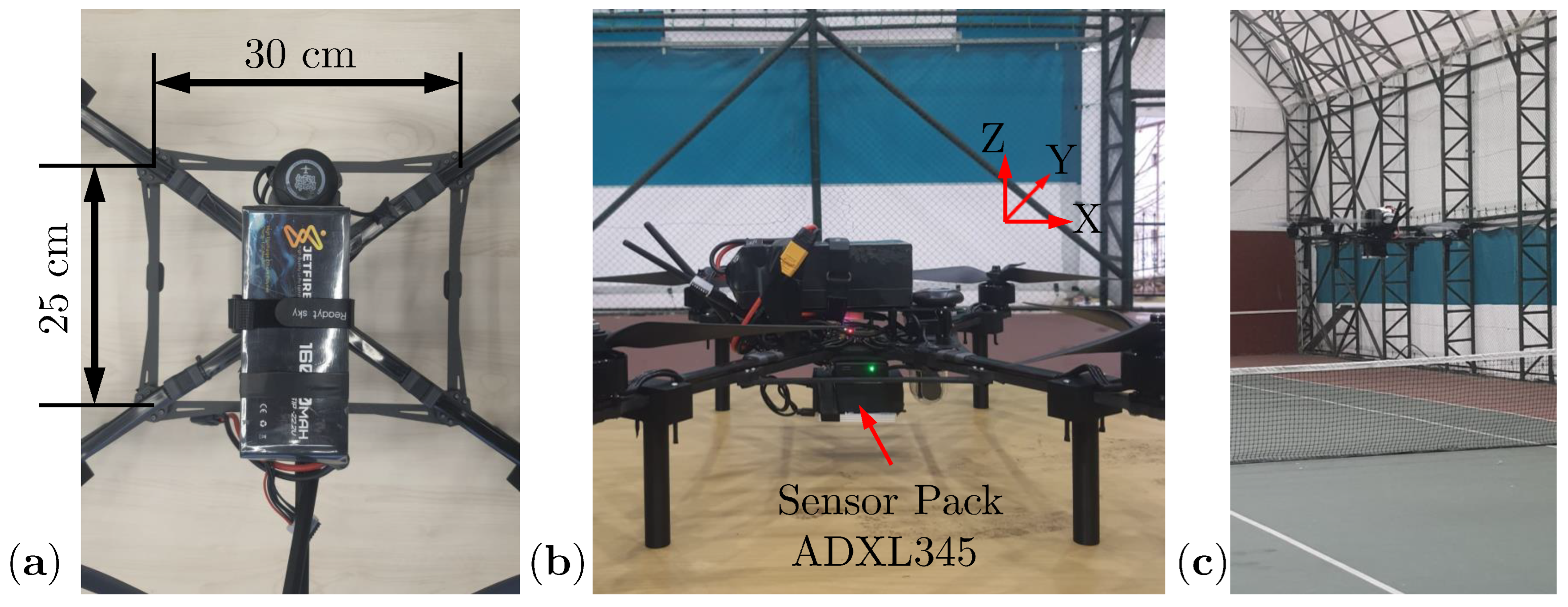
Z axes correspond to the longitudinal (roll), lateral (pitch), and vertical (yaw) rotational movements, respectively. The experimental platform is a custom-built quadrotor with a compact airframe of 25 cm × 30 cm and brushless DC motors, as illustrated in
Figure 1. The sensor pack is mounted at the center of the airframe, and during data acquisition, the UAV was operated in a controlled hovering position under indoor conditions for 40 s at each throttle level.
The dominant vibration components, including the rotational fundamental frequency and its first three harmonics, fall within the 30–200 Hz range across the full throttle sweep (10%–100%). According to the Nyquist criterion, the 800 Hz sampling rate provides a theoretical Nyquist frequency of 400 Hz. Applying a standard anti-aliasing margin of 80%–87% of the Nyquist frequency, the reliable usable bandwidth extends to approximately 320–350 Hz. This usable bandwidth comprehensively covers the fundamental rotor frequency (which reaches approximately 140–150 Hz at maximum throttle) as well as its first two significant harmonics (
–300 Hz), ensuring adequate spectral coverage without aliasing. This rate is also consistent with the ADXL345 bandwidth specifications (400 Hz at 800 Hz output data rate) and with sampling rates commonly adopted in rotorcraft vibration monitoring studies [
36,
37].
In rotor dynamics, static imbalance occurs when the center of gravity is displaced from the axis of rotation, generating vibration proportional to the displacement. Dynamic imbalance requires mass to act outside the plane of rotation, producing a rocking moment. Aerodynamic imbalance exists when forces result in unequal thrust across blades [
60,
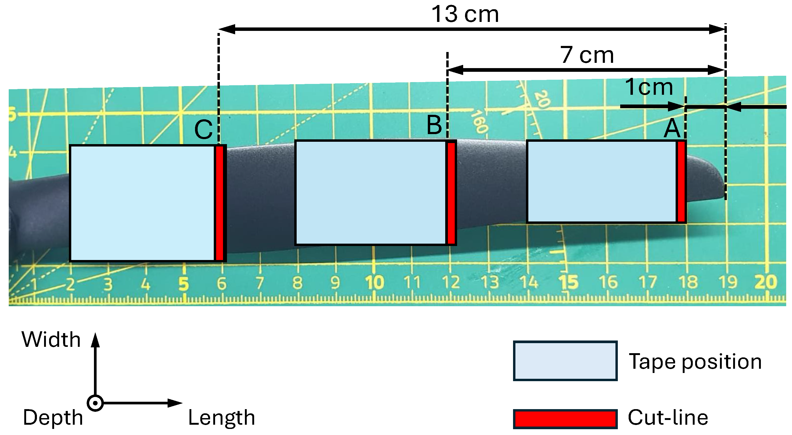
61]. In this study, a systematic fault injection protocol was developed to simulate progressively graded degradation states that accurately represent realistic rotor–propulsion deterioration mechanisms in operational UAV systems. To investigate vibration signatures associated with both early-stage damage and severe structural failure, three controlled categories of propeller anomalies were intentionally introduced. The anomaly types were designed to replicate common mechanical degradation scenarios encountered during real-world operations, including imbalance growth, surface wear, and structural damage. The spatial distribution of the induced defects was defined at three distinct radial locations along the blade, which were denoted as A, B, and C from tip to root of the propeller blade, respectively, as depicted in
Figure 2. Due to the high diameter-to-thickness ratio of UAV propellers, experimental anomalies in this study primarily induce static imbalance by radially shifting the mass center, while dynamic imbalance effects are negligible. Geometric alterations to the blade surface simultaneously introduce an accompanying aerodynamic imbalance. The investigated fault categories included:
Mass imbalance (Tape-induced imbalance): Adhesive tape was applied circumferentially around the blade at three distinct radial locations (denoted as A, B, and C). To simulate progressive imbalance severity, 5, 10, and 15 tape layers were applied individually. This fault category primarily induces centrifugal imbalance forces that scale with both added mass and radial distance from the rotation axis.
Surface degradation (Scratch faults): To simulate gradual material wear and aerodynamic surface deterioration, scratches were introduced across the full blade width with controlled penetration depths of 25%, 50%, and 75% of the blade thickness. Similar to the tape-induced imbalance, scratches were applied separately at the locations A, B, and C. Unlike pure mass imbalance, this anomaly mechanism introduces both local stiffness reduction and aerodynamic asymmetry.
Structural failure (Cut faults): Severe structural damage was emulated by introducing complete cuts across both the depth of the blade at each radial location. These faults represent critical failure states and are expected to generate pronounced broadband vibration components and substantial harmonic distortion. In contrast to imbalance and surface degradation cases, cut faults produce abrupt structural discontinuities that alter both mass distribution and bending stiffness characteristics simultaneously.
Baseline Configuration (No faults): Prior to introducing any modification, baseline (healthy) vibration measurements were recorded to establish nominal spectral envelopes under identical throttle conditions. For all anomaly scenarios, only one fault type and one severity level were present during each experiment to ensure isolation of the induced degradation mechanism. This controlled design eliminates confounding effects and allows direct comparison between fault categories and severity progression.
It is vital to emphasize that all induced fault conditions inherently affect aero-mechanical coupling by simultaneously modifying both mass distribution and aerodynamic surface properties. Although categorized experimentally, none of these physical configurations act purely mechanically or purely aerodynamically; rather, they serve as integrated operational proxies representative of realistic field damage dynamics.
To provide a clear overview of the experimental design,
Table 1 summarizes all investigated propeller conditions, including the fault type, radial location, severity level, and the total number of experimental runs. In total, 23 distinct configurations were tested, each repeated three times, yielding 69 individual flight recordings.
Each experimental run followed a throttle sweep profile, in which the throttle command was incrementally increased from 10% to 100% in 10% steps, with each level maintained for 40 s to provide sufficiently long steady-state vibration segments for robust spectral and time–frequency analysis. A stepped throttle profile was specifically selected over a continuous chirp sweep to prevent transient aerodynamic artifacts and active flight-controller stabilizations from conflating with steady-state vibration signatures. Based on spectral analysis of the healthy baseline flights, the fundamental rotor frequency (and corresponding motor RPM) scales approximately linearly with the throttle command, ranging from an average of 40 Hz (approx. 2400 RPM) at 10% throttle up to 80 Hz (approx. 4800 RPM) at 100% throttle. Since rotor imbalance excitation scales with centrifugal force (), systematic increases in angular velocity enable controlled observation of harmonic amplitude growth and frequency shift phenomena, thereby providing a physically interpretable basis for analyzing degradation-dependent vibration behavior.
To account for run-to-run variability, each experimental condition was repeated three times under the same settings. All vibration signals were recorded at an effective sampling frequency of approximately 800 Hz, which is sufficient to capture the dominant harmonic and broadband vibration components associated with rotor dynamics in small-scale UAV propulsion systems. Overall, the experimental design ensures that the acquired dataset captures a wide range of realistic rotor operating states and degradation scenarios, while maintaining strict control over confounding variables. This provides a reliable foundation for the development and evaluation of vibration-driven deep learning models for UAV anomaly detection. All data processing, signal analysis, and deep learning model development were conducted using MATLAB R2024b (MathWorks, MA, USA; license number: 41212205).
2.2. Data Augmentation Strategy
In rotary-wing UAVs, vibration responses induced by propeller degradation are primarily governed by centrifugal imbalance forces and aerodynamic asymmetry. The magnitude of these effects scales with both the severity of the defect and its radial location along the propeller blade. A central limitation in UAV fault diagnostics is the inability to observe continuous degradation progression within a single flight experiment. Since physical damage must be introduced prior to testing, measurements correspond to isolated health states rather than gradual transitions. To overcome this limitation, a severity-ordered augmentation framework was developed to reconstruct a temporally coherent degradation sequence by systematically assembling experimentally acquired flight data.
Throttle measurements from all experiments were first aggregated to determine global minimum and maximum values. Each throttle signal was mapped to a normalized 0–100% scale using global min–max normalization as follows:
where
and
were computed across all experiments. The normalized throttle was then quantized into discrete 10% plateau levels to ensure consistent operating-regime alignment across conditions. For each propeller condition, repeated flight runs were concatenated to form a single record. The concatenated signal was segmented according to throttle plateau transitions. A segment boundary was defined when the absolute change in normalized throttle exceeded a predefined threshold:
where
. Segments shorter than 5 s were discarded to avoid transient artifacts. Within each throttle plateau, vibration severity was quantified using a robust peak-to-peak metric:
where
and
denote the 97.5th and 2.5th percentiles of the vibration amplitude distribution. This metric reduces sensitivity to impulsive outliers while preserving structural amplitude growth associated with imbalance and structural discontinuities. Extracted segments were ordered according to vibration severity (primary criterion), and throttle level (secondary criterion).
It is important to clarify that the robust peak-to-peak metric serves exclusively as a sorting criterion for assembling the augmented degradation sequence; it is not used as the anomaly detection feature itself. In principle, aero-structural changes can affect multiple eigenfrequencies and apparent damping simultaneously, and a single amplitude-based metric cannot capture the full complexity of such spectral modifications. However, the anomaly detection stage relies on three-axis CWT scalograms, which preserve the complete time–frequency content of each vibration segment, including harmonic shifts, bandwidth changes, and damping-related spectral broadening. Therefore, even if a particular fault condition produces only a moderate change in peak-to-peak amplitude due to coincidental damping compensation, the CWT-based reconstruction error will still respond to the corresponding spectral redistribution. The robust peak-to-peak metric was chosen for sorting because it provides a scalar proxy that correlates well with centrifugal imbalance growth () and is straightforward to compute across all operating conditions, while the downstream deep learning model handles the full multi-frequency detection task.
The physical rationale for this dual-criterion sorting is rooted in rotor dynamics. It is important to note that the continuous degradation trajectory is reconstructed by sorting experimentally measured vibration segments according to quantified severity and operating conditions, rather than being recorded during real-time progressive damage evolution. In UAV vibration experiments, physical damage such as tape, scratches, and cuts must be introduced prior to each test flight. Continuous in-situ degradation recording during flight is not feasible under controlled laboratory conditions, because the propeller cannot be progressively damaged during operation without introducing uncontrolled confounding effects. In a rotary-wing system, the centrifugal imbalance force is governed by , where m is the imbalance mass, r is its radial distance, and is the angular velocity. As a defect grows (increasing m or altering r), the resulting vibration amplitude rises monotonically at any given rotor speed. Simultaneously, increasing the throttle raises , which amplifies the same imbalance force quadratically. Sorting primarily by vibration severity therefore arranges segments along the defect-growth axis, while secondary sorting by throttle level ensures that segments of comparable severity are ordered by increasing aerodynamic load. This two-level ordering reconstructs a physically consistent trajectory: the assembled sequence progresses from low-severity, low-speed conditions toward high-severity, high-speed operation, closely mirroring the spectral and amplitude evolution that would occur during actual in-service degradation. The resulting dataset thus captures both the amplitude scaling due to defect growth and the frequency drift associated with throttle-dependent rotor speed variation, so the assembled sequence reflects physically meaningful transitions rather than arbitrary concatenation. The time–frequency spectrograms of the augmented dataset confirm monotonic spectral evolution without artificial discontinuities, supporting the physical consistency of the proposed ordering.
Unlike datasets constructed from isolated individual failure cases, the proposed strategy systematically generates graded degradation levels derived from experimentally measured fault conditions. By ordering segments according to quantified severity and aligned operating regimes, the resulting augmented dataset forms a continuous degradation from health state to failure, which provides a structured and physically meaningful foundation for training deep learning-based anomaly detection models for rotary-wing UAVs, enabling the learning of progressive degradation dynamics instead of static fault classification. The complete severity-ordered augmentation procedure is summarized in Algorithm 1.
| Algorithm 1 Severity-Ordered Data Augmentation Strategy |
- Require:
Experimental dataset for conditions and repeats ; sampling rate ; throttle step size (i.e., 10%). - Ensure:
Augmented axis-wise sequence for each axis j; augmented segment set with metadata . - 1:
Global throttle normalization parameters - 2:
, - 3:
for do ▹ repeat for each vibration axis - 4:
- 5:
for to K do ▹ iterate propeller conditions - 6:
Concatenate repeats: , - 7:
Remove throttle NaNs and align: keep indices , set , - 8:
Mean-center vibration: - 9:
Normalize throttle: - 10:
Quantize throttle: - 11:
Detect plateau boundaries: find indices - 12:
Define segments: from - 13:
for each segment to do - 14:
if then - 15:
continue ▹ discard short/transient segments - 16:
end if - 17:
- 18:
- 19:
Compute severity: - 20:
Append to segment set: - 21:
end for - 22:
end for - 23:
Severity-ordered arrangement: sort by - 24:
Concatenate sorted segments: - 25:
end for - 26:
return ,
|
The augmented dataset is not synthetically generated; instead, every vibration segment in the augmented sequence comes from actual physical experiments conducted under controlled conditions. The augmentation procedure does not inflate the data volume beyond what was experimentally acquired; it reorganizes the experimentally measured data into a physically meaningful sequence. Accordingly, the term augmentation in this study refers to the severity-ordered reordering and assembly of measured segments, not to the generation of synthetic data points.
The monotonic ordering adopted in this framework represents a first-order physical approximation consistent with centrifugal-force-driven imbalance growth. While this assumption simplifies the actual degradation process, which may exhibit intermittent stabilization, load redistribution, or sudden damage transitions. It ensures that the training data spans the full degradation manifold in a physically interpretable manner, enabling the deep learning model to learn smooth degradation trends rather than discontinuous fault boundaries.
2.3. Deep Learning-Based Unsupervised Anomaly Detection Framework
A deep learning–based unsupervised anomaly detection framework was developed to identify abnormal vibration patterns in UAV propulsion systems utilizing the acquired augmented three-axis vibration signals. The proposed model is a three-axis fused time–frequency sequence autoencoder designed to learn the manifold of healthy UAV vibration dynamics and detect anomalies via reconstruction error. For each vibration segment, the three-axis signals are converted into a sequence of continuous wavelet transform (CWT) scalograms, encoded into latent vectors by a convolutional neural network (CNN), modeled temporally by a bidirectional gated recurrent unit (BiGRU), refined by a gated state-space (Mamba-like) block, and finally decoded to reconstruct the original scalograms.
Let denote the vibration signal measured along axis . Each dataset entry contains the vibration signal, throttle percentage, and a severity metric derived from vibration amplitude statistics. To ensure temporal consistency across axes, only samples available simultaneously in all three axes were retained.
The vibration signals were segmented using a sliding window approach. Each segment was divided into overlapping windows of length
s (1024 samples at 800 Hz) with a hop length of
s (512 samples). Consequently, each vibration segment was represented as a sequence of up to
S windows:
where
s denotes the window index. Each vibration window was transformed into a time–frequency representation using the Continuous Wavelet Transform (CWT). The CWT of window
s for axis
a is defined as:
where
denotes the wavelet basis function and * represents complex conjugation. The scalogram magnitude is computed as follows:
which improves numerical stability and compresses the dynamic range. The resulting scalograms were resized to a fixed spatial resolution of
. This specific resolution was empirically chosen to balance spectral density and computational footprint: 48 frequency bins provide sufficient logarithmic scale resolution across the relevant 10–300 Hz band without excessive oversampling, while 96 time bins across the 1.28 s window ensure a temporal resolution of approximately 13 ms. This is structurally sufficient to capture non-stationary dynamics such as turbulence-induced wobble without overloading the autoencoder memory. The three axes were stacked channel-wise to form a fused tensor, which is given in Equation (
7)
As a result, each vibration segment is represented as a sequence of time–frequency feature matrices defined as:
where
S denotes the total number of temporal steps in the sequence and
corresponds to the feature matrix extracted from the
s-th time window.
The proposed model follows an encoder–sequence–decoder architecture designed for self-supervised learning. The encoder consists of three convolutional layers with stride-2 downsampling that compress the input scalograms into a compact latent representation. Global spatial pooling followed by a fully connected layer produces a latent vector of dimension 192 representing the vibration state of each time window.
To incorporate operating-condition awareness, the throttle percentage recorded during each vibration segment is integrated into the latent representation via a dedicated conditioning pathway. Specifically, the scalar throttle value associated with each segment is passed through a small fully connected layer that projects it into a conditioning vector of the same dimension as the latent code. This conditioning vector is then added element-wise to the CNN-encoded latent vector before the temporal modeling stages. By injecting throttle information directly into the latent space, the network learns to modulate its internal representation according to the current operating regime. This design allows the BiGRU and state-space layers to distinguish between vibration amplitude changes caused by normal throttle variations and those caused by structural degradation, reducing false alarms under varying rotor speeds while maintaining sensitivity to fault-induced anomalies. This layer models both forward and backward dependencies in the vibration dynamics, capturing short- and mid-range temporal patterns in the vibration sequence.
To further enhance the modeling of long-range dependencies, a state-space modeling block inspired by the Mamba architecture is incorporated. The state-space layer evolves a latent hidden state across time steps and produces gated outputs that efficiently capture dynamic system behavior. Finally, the reconstructed scalogram is generated using a convolutional decoder, which expands the latent representation back to the original, consisting of transpose convolution layers as:
The full model, therefore, learns a mapping
The network is trained in a self-supervised manner using only healthy vibration segments. The dataset was sorted according to a severity metric derived from vibration amplitude statistics, and the lowest
of the segments were considered representative of normal operating conditions. This threshold was selected based on the composition of the sorted augmented dataset. Since the severity-ordered sequence begins with the two healthy baseline configurations (each repeated three times across the full throttle sweep), the lowest 20% of segments consists almost entirely of healthy and near-healthy recordings. The 20% boundary was verified by inspecting the severity distribution and confirming that it separates the baseline recordings from the first fault-injected conditions (5-layer tape at the outermost location), providing a natural boundary between nominal operation and the onset of detectable degradation. While alternative thresholds (e.g., 15% or 25%) could be considered, this choice ensures that the training set contains only segments whose spectral content is representative of undamaged propeller dynamics. The network parameters were optimized using the Adam optimizer with gradient clipping. The training objective minimizes the masked mean absolute reconstruction error:
where
B is the batch size. After training, anomaly detection is performed by computing the reconstruction error for each vibration segment. The anomaly score is defined as:
A decision threshold is determined from the training set using the 99th percentile of the reconstruction errors. This percentile-based thresholding approach is widely adopted in unsupervised anomaly detection because it controls the expected false alarm rate while remaining robust to non-Gaussian error distributions. The formulation of the threshold (
) is defined in Equation (
13).
After the training phase, anomaly detection is carried out by evaluating the reconstruction error of each vibration segment. A segment is considered abnormal when its anomaly score exceeds a predefined decision threshold. Specifically, if the anomaly score of the sequence
is greater than the threshold
, as expressed in Equation (
14), the segment is classified as anomalous, indicating a potential propulsion system fault.
3. Results and Discussions
3.1. Experimental Results
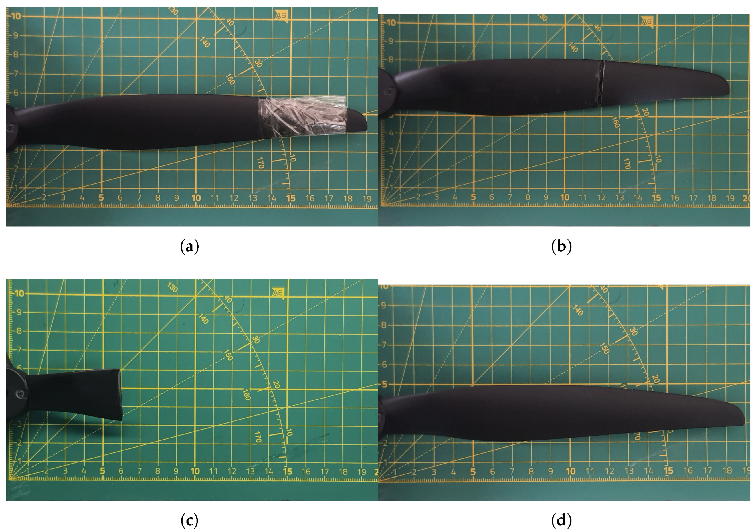
The propeller configurations shown in
Figure 3 illustrate the controlled degradation mechanisms introduced to emulate realistic UAV operational faults. The selected fault types represent three physically distinct failure modes affecting rotor dynamics: mass imbalance (See
Figure 3a), surface degradation (See
Figure 3b), and structural discontinuity (See
Figure 3c). In addition,
Figure 3d shows the baseline (healthy) propeller configuration used to establish nominal vibration envelopes.
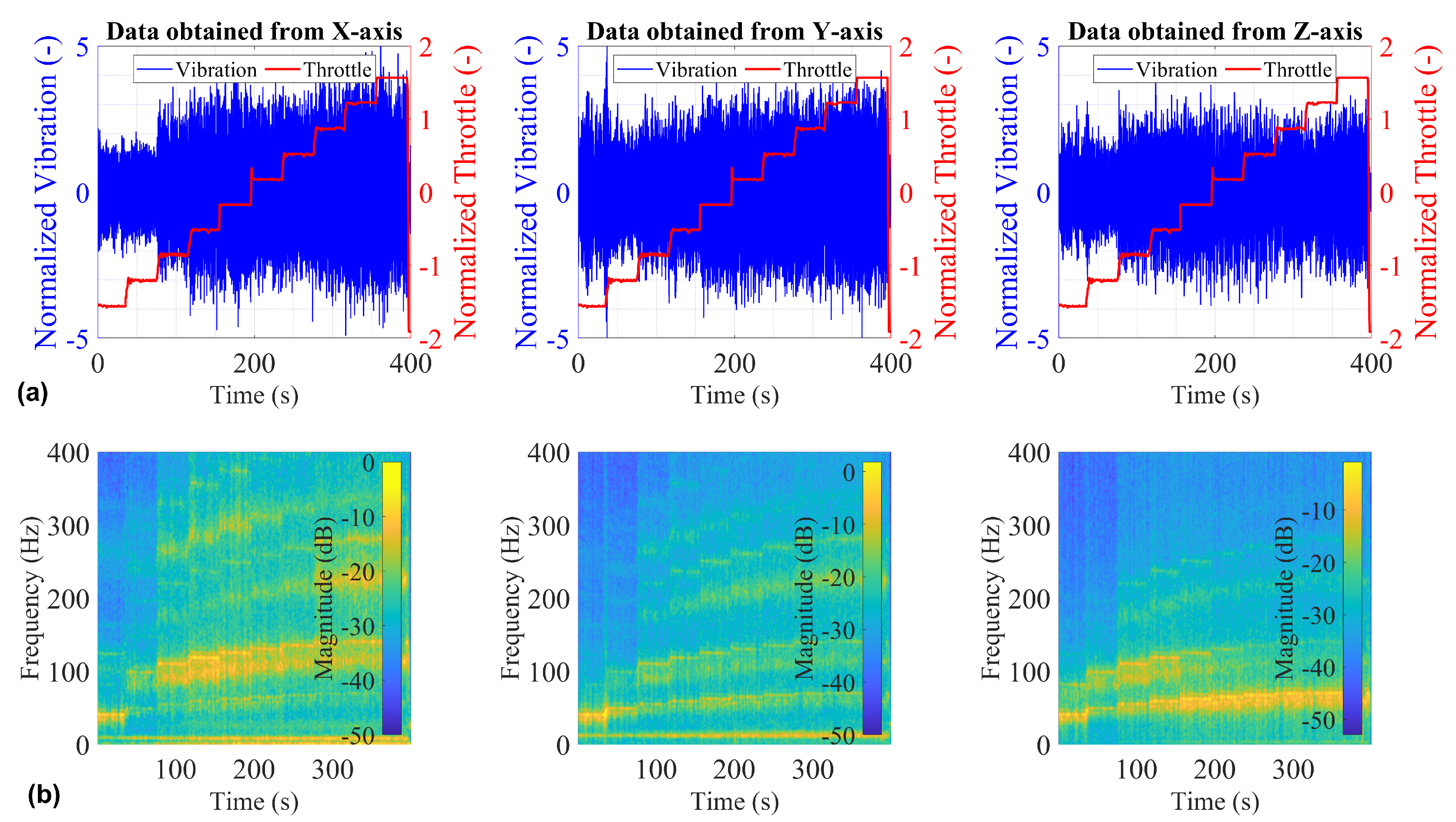
To establish a quantitative reference for subsequent degradation analysis, the vibration response of the baseline (healthy) propeller is first examined. As shown in
Figure 4, the stepped throttle rose from 10% to 100% (40 s per level) produces a clear monotonic increase in vibration amplitude across all three axes. For visualization purposes (
Figure 4a), both vibration signals and throttle positions were normalized using the z-score method to present them on a common scale while preserving their temporal evolution. The corresponding time–frequency representations reveal two dominant spectral components. A persistent structural mode appears near 35–45 Hz, remaining horizontally stable across all throttle levels, suggesting unchanged stiffness and symmetric mass distribution. In addition, a rotor-induced harmonic band is observed primarily between 60 and 140 Hz, with spectral magnitude increasing progressively with throttle. At high throttle, the rotor band magnitude approaches approximately
to
dB, while broadband content above 200 Hz remains limited (below
dB). The narrowband harmonic structure and clear modal separation confirm symmetric mass distribution and undisturbed stiffness characteristics in the healthy configuration.
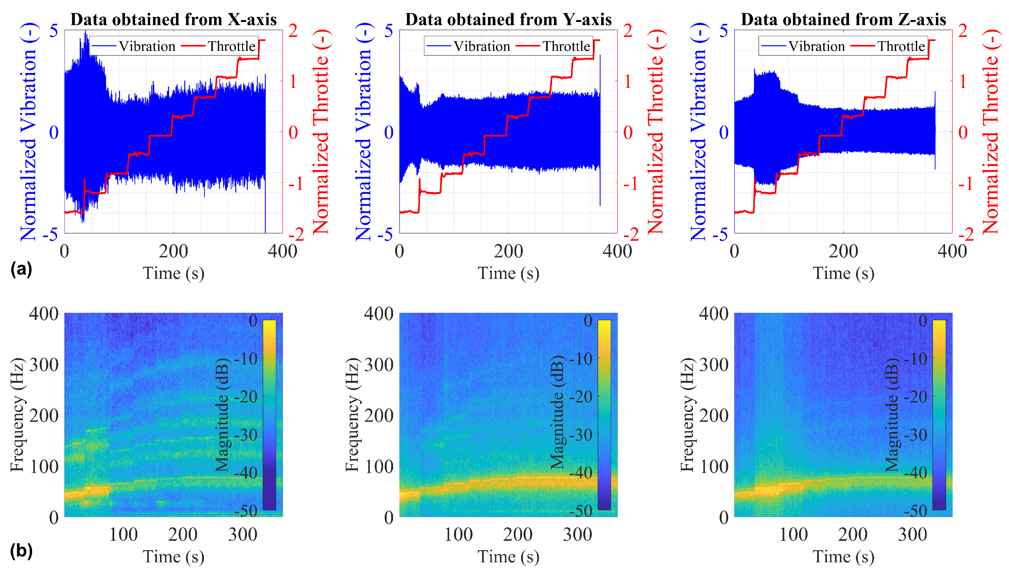
Figure 5 presents the time-domain vibration signals and corresponding time–frequency spectrograms for the complete cut introduced at radial location C. This configuration represents the most severe structural degradation scenario investigated in the experimental campaign. Unlike the smooth and monotonic amplitude growth observed in the healthy case, the cut configuration demonstrates pronounced transient bursts during the initial throttle steps (0–100 s) and persistent envelope irregularities at steady-state levels, indicating structural discontinuity and asymmetric mass distribution. The spectrograms further reveal marked spectral redistribution. While the healthy propeller blade harmonic band was primarily confined within 60–140 Hz, the cut case exhibits energy spreading from approximately 40 Hz up to nearly 180 Hz. Spectral magnitude increases from roughly
dB in the baseline condition to values approaching 0 dB in the damaged state, corresponding to an approximate 15 dB increase in power.
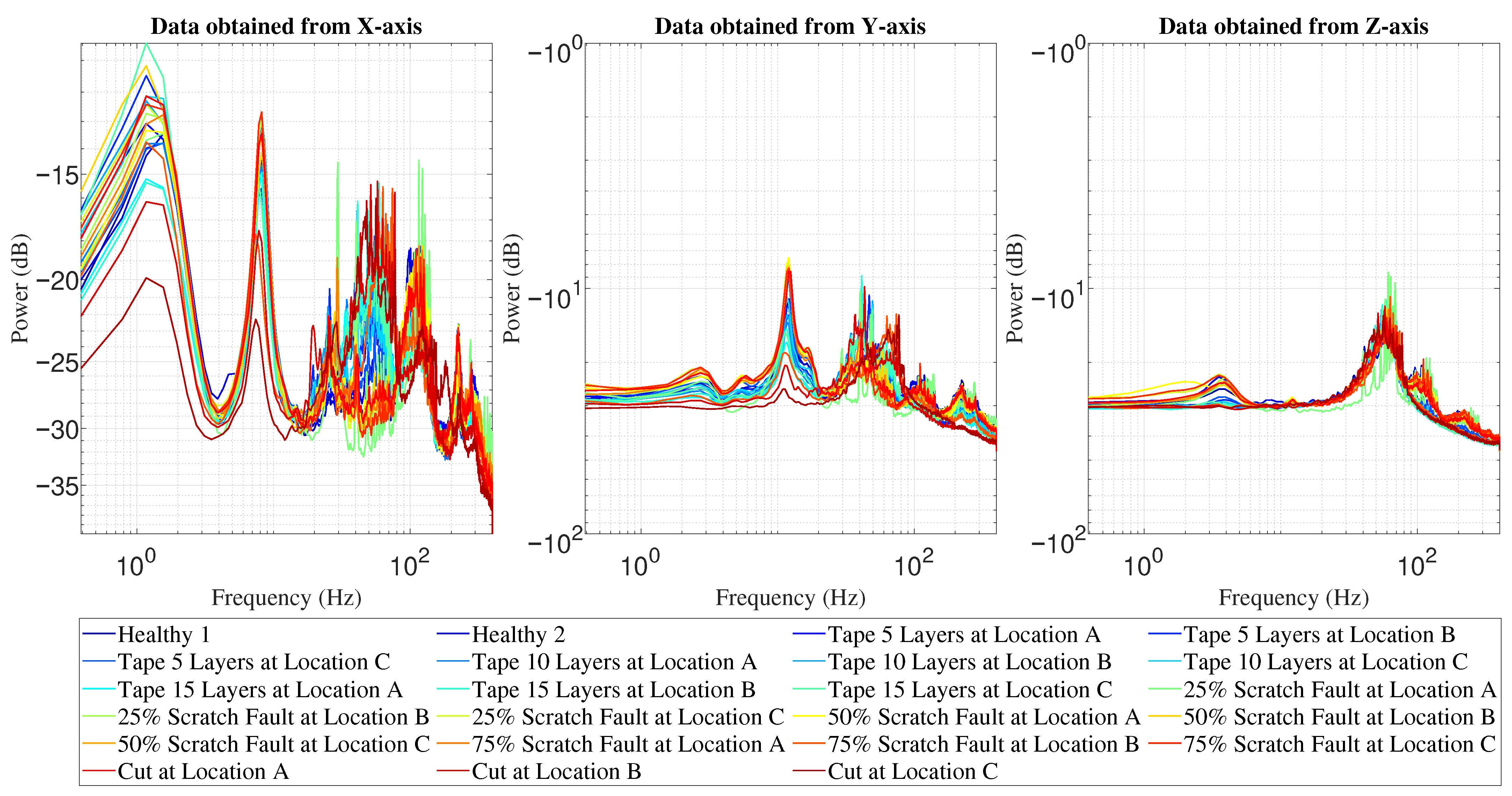
The frequency-domain comparison in
Figure 6 clearly highlights fault-dependent spectral modifications across all axes. Each curve corresponds to a specific fault type and location, including healthy, tape-induced imbalance, scratch faults (25–75%), and complete cut cases. Under healthy operation, the time-averaged vibration response across the entire throttle sweep exhibits a dominant broadband rotor harmonic region. Because vibration energy scales quadratically with rotor speed, the average PSD is heavily dominated by the high-throttle operational regime, producing a visible peak centered approximately at 60–80 Hz (representing 60% to 100% throttle settings). The power levels reach close to
dB in the X-axis, while broadband energy above 150 Hz remains suppressed below roughly
dB, indicating predominantly periodic excitation. Tape-induced imbalance mainly increases the amplitude of this fundamental harmonic without substantially widening the spectral bandwidth, preserving the narrowband structure. Progressive scratch faults (25–75%) introduce moderate harmonic broadening and elevate spectral content within the 80–150 Hz range, reflecting partial stiffness and aerodynamic asymmetry. In contrast, the complete cut at location C produces pronounced broadband amplification, with high-frequency components between 100 and 200 Hz increasing by approximately 10–15 dB relative to the healthy baseline. The harmonic peak becomes visibly less distinct, and spectral energy spreads over a wider band, particularly along the X-axis, indicating loss of harmonic purity and reduced periodicity. These results demonstrate a clear transition from narrowband harmonic amplification (imbalance-type faults) toward broadband spectral redistribution and harmonic distortion in severe structural failures.
As shown in
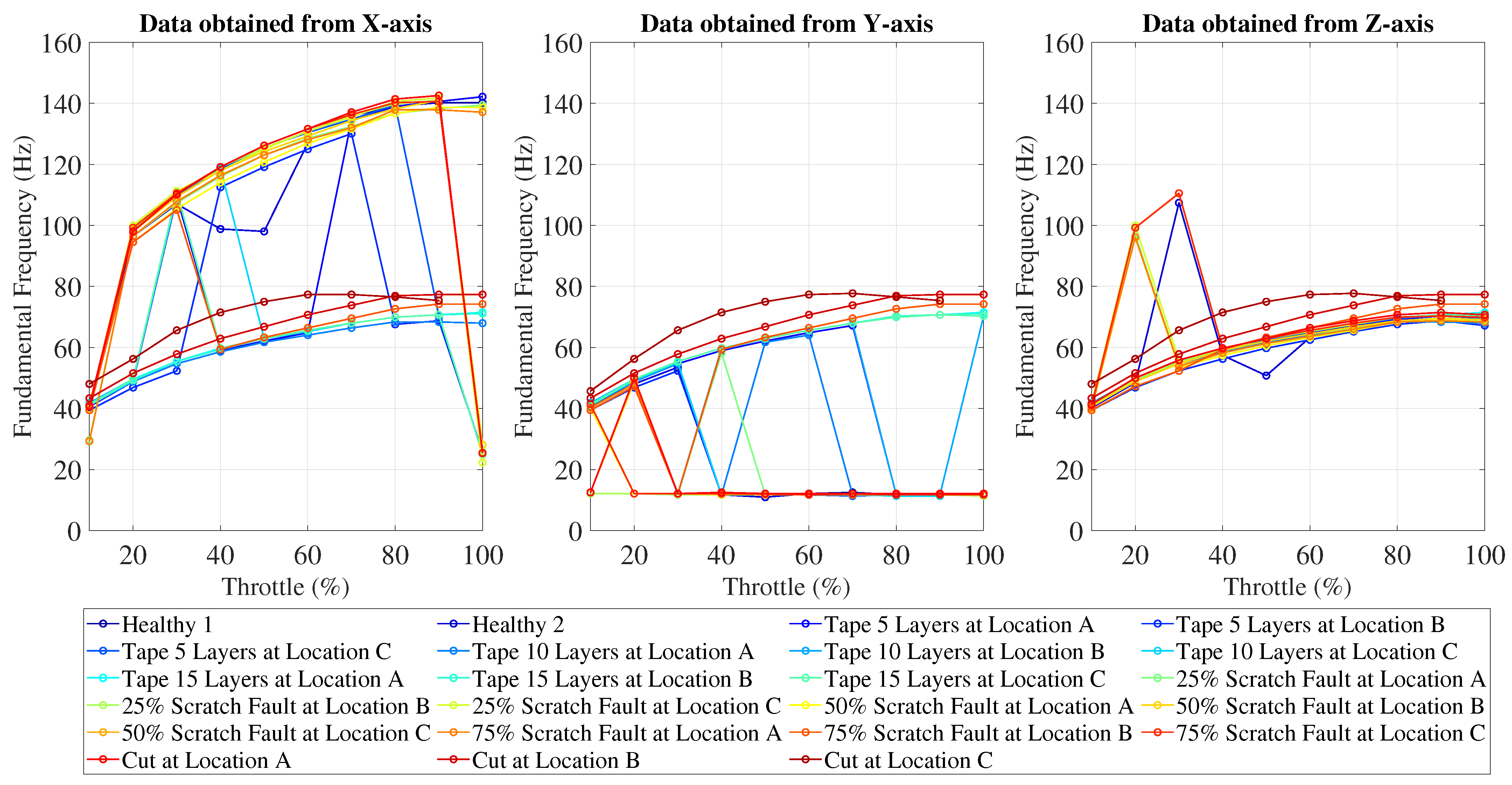
Figure 7, the healthy configurations exhibit a nearly linear increase in fundamental frequency with throttle, rising from approximately 40–45 Hz at 20% throttle to about 140–150 Hz at full throttle along the X-axis. Similar monotonic trends are observed in the Y- and Z-axes, although with lower absolute magnitudes (approximately 40–75 Hz at 100% throttle). Tape-induced imbalance and low-severity scratch faults largely preserve this linear scaling behavior, indicating that rotor speed remains the dominant excitation source. In contrast, severe faults, particularly the complete cut cases, exhibit abrupt frequency drops at high throttle levels (e.g., sudden collapse to 25–30 Hz in some X-axis cases), reflecting loss of stable harmonic tracking. Importantly, these discontinuities do not represent actual physical leaps in rotor angular velocity. Since the fundamental frequency tracking algorithm targets the maximum spectral peak, severe damage strips the
rotor harmonic of its dominance. Consequently, the algorithm tracks higher-energy structural resonances or broadband noise peaks instead. These signal processing artifacts accurately capture the destruction of periodicity and stable harmonic behavior, clearly differentiating structural failure from mild imbalance-type degradations.
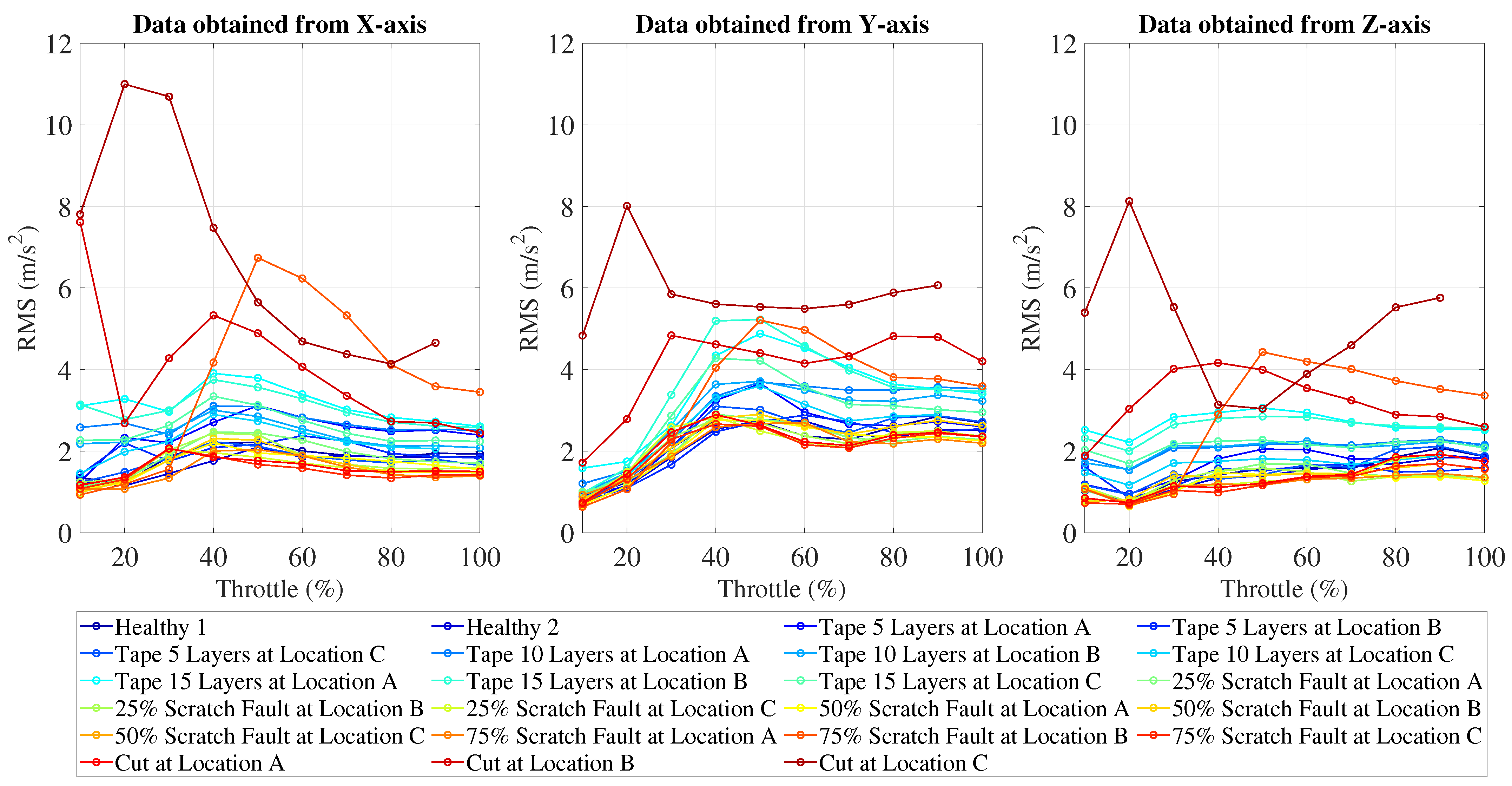
Figure 8 illustrates the evolution of vibration amplitude with throttle for all tested configurations. Under healthy conditions, Root mean square (RMS) levels increase gradually with throttle, remaining within approximately 1.5–3 m/s
2 across all axes. Tape-induced imbalance and moderate scratch faults produce incremental amplitude growth, typically remaining below 4 m/s
2. However, the complete cut cases exhibit pronounced amplification, particularly in the X-axis, where RMS values exceed 10–11 m/s
2 at intermediate throttle levels representing more than a threefold increase relative to baseline. The Y- and Z-axes also show elevated responses (up to 8 m/s
2 and 6 m/s
2, respectively). These results confirm that while mild faults primarily affect harmonic amplitude scaling, severe structural discontinuities drive substantial energy amplification and cross-axis vibration growth, providing a strong discriminative feature for anomaly detection.
3.2. Severity-Ordered Augmented Dataset
A key limitation in the existing UAV fault-diagnosis literature is that damage initiation and progression cannot be reproduced during a single controlled experiment (i.e., the “moment of failure” is typically missing). In practical experiments, damage must be introduced prior to flight, making it impossible to record the true temporal evolution of degradation under controlled operating conditions. To address this limitation, a severity-ordered augmentation framework was developed to reconstruct a physically consistent healthy-to-failure vibration sequence by systematically concatenating datasets obtained in this study.
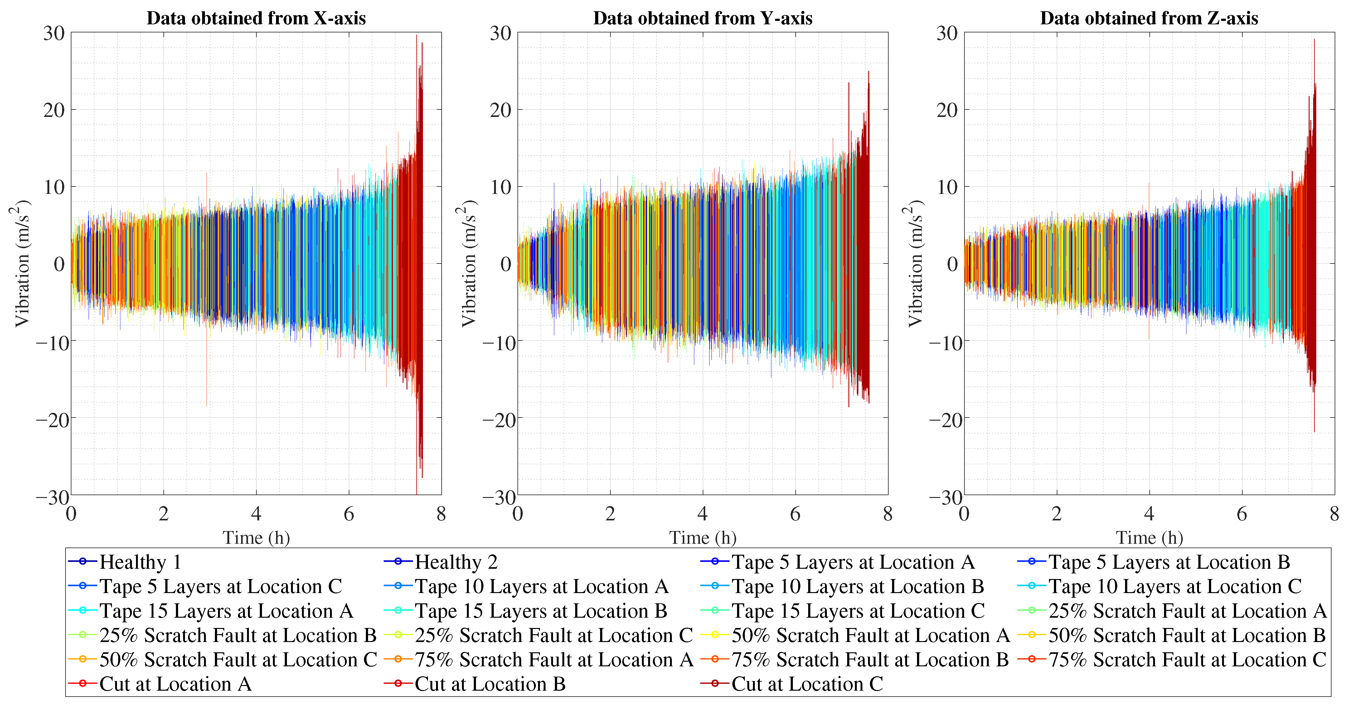
Each flight lasted 400 s and was conducted under stepped throttle excitation (10–100%, 40 s per level). Every configuration was repeated three times, and experiments were performed for 23 distinct propeller conditions, including healthy, tape-induced imbalance, progressive scratch faults (25–75%), and complete cut failures. By concatenating all repetitions and conditions following a physically meaningful ordering rule, approximately 7.5 h of augmented vibration data were generated for each axis.
The augmentation procedure was governed by two physically interpretable parameters: throttle position and vibration severity. First, all recordings were globally normalized using the z-score technique with respect to the throttle to ensure consistent operating-regime alignment. The throttle signal was converted to a 0–100% scale and quantized into discrete plateau segments. Within each throttle plateau, vibration segments were extracted and evaluated using a robust peak-to-peak severity metric, which reduces sensitivity to transient outliers while preserving structural amplitude characteristics. Segments were then sorted primarily by vibration severity and secondarily by throttle level. This ordering ensures that the assembled time series reflects a monotonic degradation progression under comparable aerodynamic loading conditions rather than arbitrary concatenation.
Figure 9 presents the resulting augmented time-domain signals for the X-, Y-, and Z-axes. A clear and gradual expansion of vibration envelopes is observed across the constructed timeline. Early segments, dominated by healthy and low-severity conditions, exhibit narrow amplitude bands. As the sequence progresses, moderate growth appears under scratch-induced surface degradation. It is observed that tape-induced imbalance produces substantially higher amplitudes than scratch faults, and its vibration levels approach those of structural cut failures. This observation highlights a critical physical distinction: while surface degradation primarily introduces aerodynamic roughness with limited mass redistribution, circumferential tape application alters aerodynamic loading, leading to amplified periodic excitation and stronger centrifugal imbalance forces. As a result, mass imbalance faults exhibit vibration magnitudes closer to structural discontinuities than to superficial surface defects.
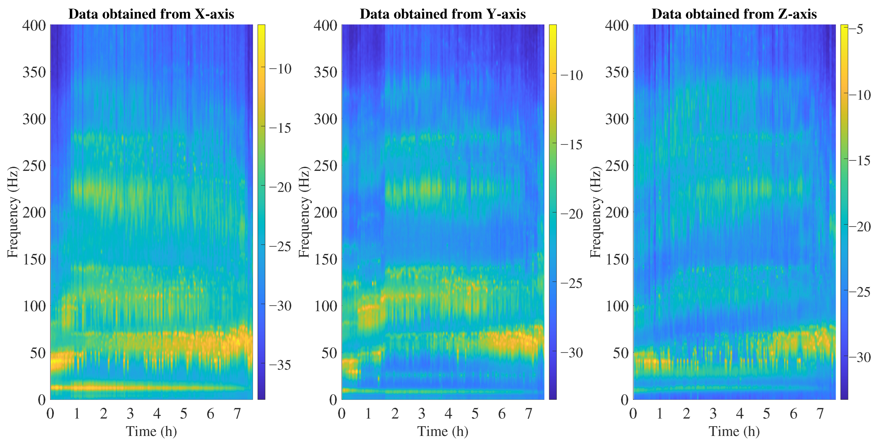
Figure 10 illustrates the time–frequency spectrograms of the augmented vibration data acquired along the X, Y, and Z axes over a continuous 7-h period. Initially, the most significant vibrational energy is concentrated within the low-frequency regime (0–100 Hz) across all three axes, characterized by a steady, continuous harmonic presence near 50 Hz, which reflects the baseline nominal operations. As severity increases, harmonic amplification intensifies, followed by broadband spectral spreading in severe imbalance and cut conditions.
After the first hour of operation ( h), a highly distinct, sustained high-frequency band emerges between 200 Hz and 250 Hz. This band is heavily localized to the Y-axis, faintly transient on the Z-axis, and entirely absent on the X-axis. As the timeline progresses into the 4-to-7-h window, the previously distinct harmonic bands begin to exhibit severe spectral smearing and background noise elevation across all axes (most visibly blurring the 150–200 Hz regions). Unlike the abrupt spectral transition seen, the augmented dataset exhibits a monotonic spectral evolution. This continuity confirms that the proposed severity and throttle-based ordering preserves the underlying dynamics and avoids artificial discontinuities.
The augmented sequence exposes intermediate degradation states that are not observable in standalone experiments, which constructs a realistic spectral pathway from initial anomaly to complete structural failure. From a predictive maintenance perspective, this continuous degradation manifold provides the temporally coherent structural information required for deep learning algorithms to model progressive fault evolution rather than discrete, isolated fault classes.
3.3. Anomaly Detection Performance of the Proposed Architecture
The anomaly detection performance of the proposed architecture was evaluated by comparing it with three widely used unsupervised anomaly detection approaches: Isolation Forest, One-Class Support Vector Machine (SVM), and Long Short-Term Memory Autoencoder (LSTM–AE).
All models were trained using the developed augmented dataset and the same training protocol. The lowest 20% severity segments were treated as normal operating conditions during training. The anomaly detection threshold was defined as the 99th percentile () of the reconstruction errors computed on the training set. Segments with reconstruction errors exceeding this threshold were classified as abnormal.
Based on this labeling, the anomaly detection performance was quantified using precision, recall, F1-score, and the area under the receiver operating characteristic curve (AUROC). These metrics evaluate the ability of the models to correctly identify abnormal vibration patterns associated with propeller degradation while minimizing false alarms during normal operation. The comparison results are summarized in
Table 2.
Isolation Forest achieved an F1-score of 0.1886 and an AUROC of 0.7215, indicating that although the method can detect extreme outliers, it struggles to capture subtle temporal patterns present in vibration signals. Similarly, One-Class SVM slightly improved the detection capability, reaching an F1-score of 0.2308 and an AUROC of 0.7579; however, its performance remains limited due to the absence of explicit temporal modeling.
The LSTM–AE demonstrated a substantial improvement over the classical approaches by modeling sequential dependencies in the vibration data. This model achieved a precision of 0.9921 and a recall of 0.3014, corresponding to an F1-score of 0.4630 and an AUROC of 0.9027. These results confirm the benefit of temporal sequence modeling for anomaly detection in propulsion vibration signals.
The proposed CNN–BiGRU–SSM–AE architecture achieved the best overall performance across all evaluation metrics. In particular, it obtained a precision of 0.9959, a recall of 0.4428, and the highest F1-score of 0.6131, along with an AUROC of 0.9284. The improved detection capability can be attributed to the complementary roles of the architectural components. The convolutional encoder extracts discriminative time–frequency features from the CWT scalograms, the bidirectional GRU captures temporal dependencies in both forward and backward directions, and the state-space module models long-range temporal dynamics within vibration sequences.
Table 3 presents a qualitative comparison with recent UAV anomaly detection studies to better understand the results of the proposed methodology. Since each of the existing studies uses different datasets, failure types, and test conditions, a direct numerical comparison is impractical. Therefore, the comparison focuses on the differences in methodology.
As shown in
Table 3, most existing methods treat faults as discrete states and do not model the gradual transition from healthy to degraded conditions. Chen et al. [
41] used convolutional autoencoders with support vector data description for flight parameter anomaly detection. Jeon et al. [
42] applied LSTM autoencoders to quadcopter vibration signals under discrete structural faults. Jung et al. [
36] used super-resolution upscaling to handle low-sampling-rate vibration data before LSTM-AE-based detection in rotorcraft. Fang et al. [
50] proposed a dual-stream coupled autoencoder for cross-system fault detection, and Jasra et al. [
51] compared LSTM, GRU, CNN, and Transformer architectures for flight data anomaly detection. Similarly, the discrete-fault methods such as residual-based detection [
15], stacked models for actuator faults [
16], multi-auxiliary task learning [
17], autoencoder-based UAV detectors [
41,
42,
43], and deep neural network classifiers [
45,
46] all rely on fixed, pre-defined fault categories without modeling transitions between healthy and faulty states. In contrast, the proposed framework uses a continuous degradation sequence for training, where the CNN–BiGRU–SSM–AE learns from an augmented trajectory that covers healthy operation, intermediate severities, and structural failure. Rather than memorizing isolated fault patterns, the model learns the spectral evolution of progressive degradation. Combined with throttle-aware conditioning, this allows the detector to identify early-stage deviations that fall between discrete fault categories, which explains the improved recall and AUROC in
Table 2. Furthermore, the use of three-axis CWT representations with the CNN–BiGRU–SSM–AE architecture also provides joint spatial and temporal feature modeling, which is absent in most existing approaches. Instead of learning separate fault categories, the proposed approach learns from the smooth spectral and amplitude transitions that characterize real-world progressive deterioration.
3.4. Ablation Study of the Proposed Architecture
To further investigate how each architectural component contributes to the anomaly detection capability, an ablation study was conducted by progressively modifying the proposed CNN–BiGRU–SSM–AE architecture. While the previous subsection demonstrated that the proposed architecture achieves the best overall anomaly detection performance, it is important to understand which components are responsible for these improvements. For this purpose, three progressively enhanced architectures were evaluated as follows:
- 1.
CNN-AE—a baseline model that uses only convolutional encoding and decoding of CWT scalograms.
- 2.
CNN–BiGRU-AE—temporal modeling is introduced using bidirectional gated recurrent units.
- 3.
CNN–BiGRU–SSM–AE—the complete architecture that integrates state-space temporal modeling together with throttle-aware conditioning.
This analysis provides insight into how each architectural enhancement affects reconstruction quality and anomaly detection behavior. Reconstruction statistics and anomaly detection behavior of the evaluated models are summarized in
Table 4.
The CNN-AE baseline model demonstrates the most conservative detection behavior, flagging 15.24% of all segments and 18.84% of test segments as anomalous. While this indicates stable reconstruction performance, the absence of temporal modeling limits the model’s ability to capture progressive vibration changes associated with evolving faults.
Introducing temporal modeling through the CNN–BiGRU–AE architecture significantly increases anomaly sensitivity. The anomaly flag rate rises to 35.56% for all segments and 44.20% for the test set, while the training reconstruction error decreases from 0.5384 to 0.5169. This suggests that the model better captures the temporal dynamics of normal vibration patterns but also becomes more sensitive to operational variations.
The proposed CNN–BiGRU–SSM–AE architecture achieves a more balanced detection behavior. The anomaly flag rate decreases to 22.27% across all segments and 27.54% on the test set while maintaining competitive reconstruction performance. Additionally, the model produces the highest anomaly threshold (), indicating that the learned representation of normal operating dynamics is less sensitive to expected vibration variations.
Overall, the results demonstrate a clear progression in model capability. The CNN-AE baseline provides stable but conservative anomaly detection, while the CNN–BiGRU–AE architecture improves sensitivity by incorporating temporal modeling. By integrating state-space dynamics together with throttle-aware conditioning, the proposed CNN–BiGRU–SSM–AE architecture achieves a more balanced detection behavior. This architecture reduces sensitivity to operating-condition variability while maintaining effective detection of degradation-related vibration patterns. Lower reconstruction errors on normal training data indicate better modeling of healthy dynamics, whereas lower anomaly flag rates indicate a reduced tendency to produce false alarms.
4. Conclusions
This study investigated vibration-based anomaly detection in rotary-wing UAV propulsion systems by integrating controlled physical experiments, severity-ordered data augmentation, and advanced deep learning architectures. The main conclusions drawn from this work are presented as follows:
- 1.
Through a rigorous experimental campaign, we analyzed three primary propeller degradation modalities: mass imbalance, surface wear, and structural failure. The findings indicate that each defect leaves a distinct vibrational footprint. While healthy propeller blades maintained stable, well-defined harmonic structures, tape-induced imbalances elevated harmonic amplitudes without substantially broadening the spectral bandwidth. Conversely, surface degradation caused moderate spectral widening, and severe structural failure triggered intense broadband energy amplification alongside pronounced dynamic instability. These results validate that specific degradation mechanisms generate unique, exploitable vibration signatures for reliable anomaly detection.
- 2.
To overcome the limitation of missing continuous progression within a single controlled experiment, a severity-ordered augmentation framework was developed to reconstruct a realistic degradation trajectory from healthy operation to structural failure. By organizing experimentally recorded vibration segments according to throttle level and vibration severity, approximately 7.5 h of augmented multi-axis vibration data were generated. This augmentation process exposes intermediate degradation stages that are typically absent in conventional datasets, allowing learning algorithms to observe a realistic progression of mechanical deterioration.
- 3.
An unsupervised anomaly detection framework was developed based on a hybrid CNN–BiGRU–SSM–AE architecture. Comparative experiments with classical unsupervised methods, including Isolation Forest, One-Class SVM, and LSTM–AE, demonstrated that the proposed architecture achieves the best overall detection performance. The model reached a precision of 0.9959, a recall of 0.4428, an F1-score of 0.6131, and an AUROC of 0.9284, indicating a strong ability to distinguish abnormal vibration behavior from normal propulsion dynamics.
- 4.
The ablation study clarified the role of each architectural component. The CNN–AE alone provided stable reconstruction but limited sensitivity to evolving faults. Introducing BiGRU layers improved the model’s ability to capture temporal dependencies in vibration signals. Incorporating the state-space module together with throttle-aware conditioning produced a more balanced detection behavior by reducing false alarms while maintaining sensitivity to degradation-related changes. These results suggest that modeling both temporal structure and operating conditions is necessary for reliable anomaly detection in UAV propulsion systems.
This work shows the value of integrating physical insight into degradation patterns with data-driven learning for UAV health monitoring. By allowing the model to learn from a continuous degradation trajectory rather than isolated fault cases, the proposed framework enables more reliable early-stage anomaly detection and provides a promising direction for predictive maintenance in UAV propulsion systems.
Several limitations of the present study should be noted. First, the continuous degradation trajectory is reconstructed by sorting experimentally measured segments rather than being recorded during real-time progressive damage. Although the severity-ordered arrangement produces a monotonically evolving sequence consistent with centrifugal-force-driven imbalance growth, real-world degradation may exhibit non-monotonic behavior such as intermittent stabilization or sudden damage transitions. Incorporating non-monotonic degradation models and stochastic ordering strategies is a direction for future work. Second, the current benchmarks focus on unsupervised methods from three major paradigm families; comparison with additional recent architectures (e.g., Transformer-based autoencoders, diffusion-based anomaly detectors) could further strengthen the evaluation. Third, the experiments were conducted under controlled laboratory conditions with a single UAV platform, and the generalizability of the framework to different rotor configurations, environmental conditions, and in-flight scenarios remains to be validated. Fourth, the current framework treats the nominal vibration signature as a deterministic baseline derived from a single UAV unit. In practice, even structurally identical UAVs will exhibit unit-to-unit variability in their vibration characteristics due to manufacturing tolerances, bearing wear states, motor aging, and differences in aero-mechanical coupling. The healthy baseline learned by the autoencoder is therefore specific to the tested unit, and deploying the model on a different unit of the same model would likely require re-acquisition of baseline data and re-training or fine-tuning of the anomaly detection threshold. Addressing this limitation through transfer learning, domain adaptation, or variability-aware training strategies that account for the stochastic nature of structural dynamics across nominally identical platforms is an important direction for future research.