1. Introduction
The diversification and increased use of UAVs have raised new issues and concerns regarding flight safety. Factors such as engine failures and collision risks are significant problems that prevent the safe landing of UAVs [
1,
2,
3,
4]. With GPS-based controlled automation, UAVs can be safely guided to target landing areas in emergency landing situations [
5]. GPS-based controlled automation systems are being developed to enhance the flight safety of autonomous UAVs [
6]. Advances in GNSS-based navigation and autonomous control systems have significantly improved global positioning accuracy. However, local perception of the landing area is critical for the safety of UAV operations [
7,
8].
The integration of cameras and artificial intelligence algorithms into UAVs has diversified their applications [
9]. Optical cameras and specialised cameras, utilising cameras operating within embedded systems, enable UAVs to be directed towards specific targets. Landing markers can serve as a solution-oriented method for these guidance processes [
10,
11,
12,
13,
14]. However, optical sensing is inherently limited at night and in adverse weather conditions, such as smoky and foggy conditions, where lighting constraints significantly reduce detection reliability. Thermal cameras offer an alternative sensing method that provides detection independent of visible light by capturing infrared radiation emitted from objects [
15,
16,
17,
18].
Existing studies on thermal-assisted UAV landing typically rely on active infrared beacons, electrically heated markers, or GNSS-supported navigation frameworks. Moreover, most prior work evaluates thermal perception in isolation, without addressing the domain gap between optical and thermal sensing modalities that naturally arises in real-world UAV operations [
19,
20,
21].
This study systematically investigates how different fusion strategies affect deep learning detection performance in optical and thermal domains, unlike previous studies that focused on visual enhancement or single-mode detection. The study quantitatively compares detection accuracy, generalisation capability, and robustness under varying environmental conditions, demonstrating the practical applicability of thermal helipad design as a safety aid at the detection level for UAVs and vertical take-off and landing (VTOL) platforms, and aims to ensure that the thermal helipad design is clearly visible for comfortable landing with thermal cameras under night conditions.
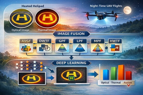
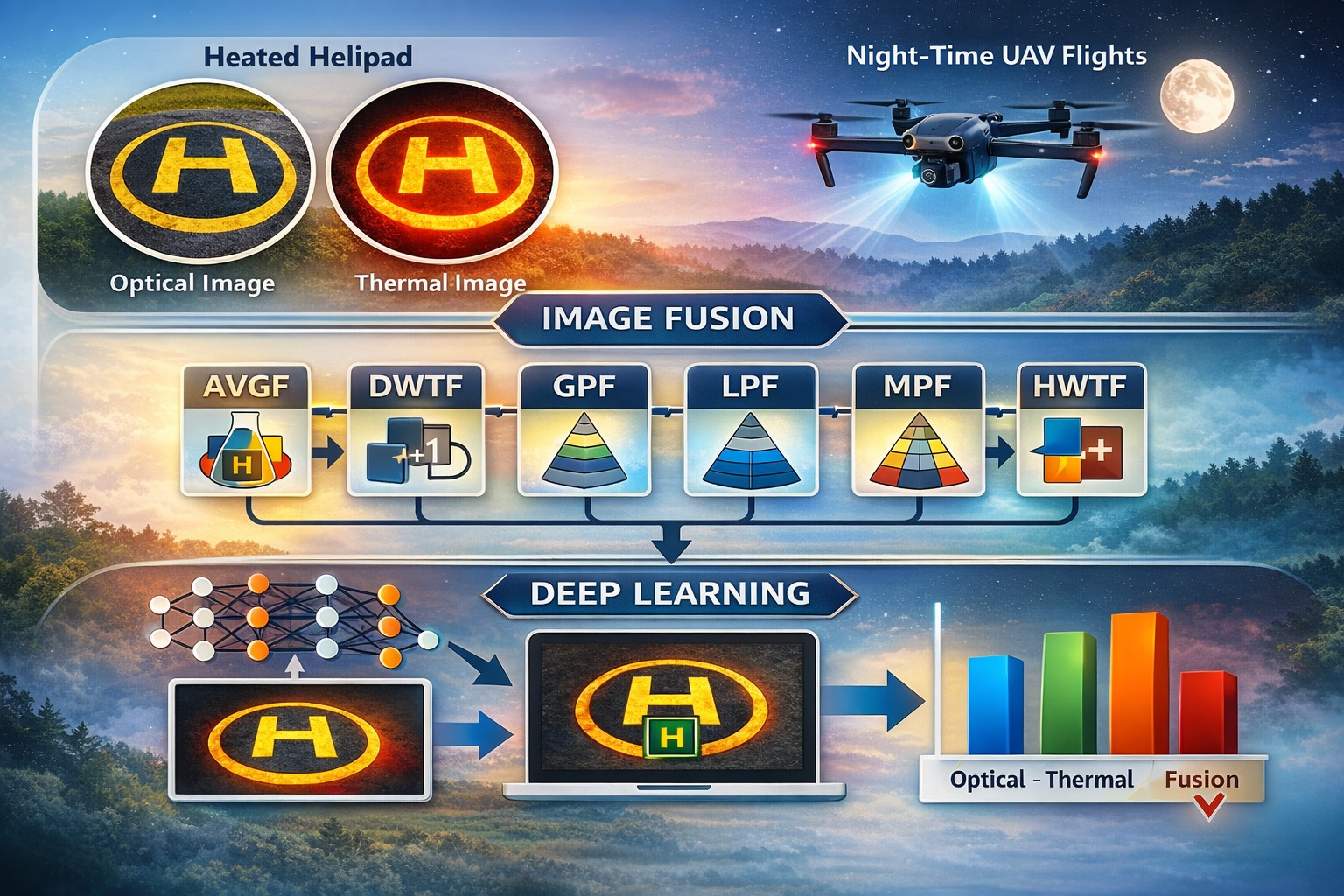
Within this framework, optical and thermal images captured during actual UAV flights under daytime and night-time conditions were fused using multiple classical image fusion techniques. The fused images were then utilised to train and evaluate deep learning-based object detection models using the YOLOv8 architecture, with comparisons subsequently made.
2. Related Works
2.1. Deep Learning Landing Systems
Wang et al. conducted a study to create landing stabilisation using a stabilisation platform that enables the UAV to land on the ship’s deck platform. The UAV aimed to land on a stable landing plane on a swaying ship using a moving mechanism with an illuminated H letter on the landing platform [
10]. Mohammadi and colleagues conducted a study on the autonomous landing of UAVs on moving landing target markers. With the model they developed, they continued their work on predictive control, vision-based localisation, and landing signal tracking [
11]. Wubben and colleagues developed a solution using the OpenCV library and low-cost, low-resolution cameras for ArUco landing markers placed on the ground, to enable UAVs to land with high precision [
12]. In their work, Badakis and colleagues conducted landing studies using infrared sensors beyond GPS. When they failed to achieve the desired results at this point, they focused on a camera-based landing solution on a platform with an ArUCO landing marker [
13]. Liu et al. presented a study on the landing of UAVs on fixed landing markers using nested equilateral triangles as landing markers [
14]. Nguyen and colleagues tracked the landing marker on the ground and planned its position using a Convolutional Neural Network (CNN) and algorithms developed on the previously trained lightDenseYOLO [
7].
2.2. Areas of Use of Thermal UAVs
Thermal UAVs are used in firefighting as an innovative technology for fire detection and intervention management. During a fire, thermal imaging can detect hot spots within smoke, which can determine the direction and intensity of the fire’s spread. Particularly in forest fires, it is necessary to quickly scan large areas and make strategic interventions. Identifying fire fronts through thermal imaging enables more effective deployment of response teams. The ability of thermal UAVs to provide effective imaging in dark and night-time conditions also allows for 24 h uninterrupted fire monitoring [
15,
16,
17].
Thermal UAVs play a life-saving role in search and rescue operations. Their ability to detect people when the heat emitted by the human body is higher than the ambient energy makes thermal UAVs critical for locating people trapped under debris after natural disasters, searching for missing persons, and finding people stranded in difficult terrain conditions. Thanks to this technology, the chances of saving lives in rescue operations where time is of the essence are significantly increased. For these reasons, thermal UAVs are critical for rapid damage assessment and intervention planning in Disaster Management and Emergency Services. Following natural disasters such as earthquakes and floods, they are considered rapid assessment tools for quickly evaluating the safety status of buildings, identifying hazardous areas, and understanding the scale of the crisis. However, if the search and rescue area is very large, it is more effective and efficient to use thermal UAVs based on their potential battery endurance, focusing on the pre-detection of the area and the search and rescue operation management plan [
18,
19,
20].
In wildlife monitoring and conservation studies, thermal UAVs are used as an effective tool for observing and protecting wildlife [
21]. In the monitoring of nocturnally active animals, population counts and detection of poaching activities, thermal UAVs can detect the thermal differences emitted by animals and animal behaviour [
22]. Thermal UAVs allow animals to be monitored in their natural habitats with minimal disturbance in the surveillance of large natural habitats [
23]. In studies that will make an important contribution to the protection of endangered species and the maintenance of ecosystem balance, studies are carried out for the detection and interpretation of thermal images with thermal UAVs [
24].
In the Construction and Building Inspection Sector, Thermal UAVs have the potential to be used as rapid pre-assessment elements to assess the health status of buildings. It is possible to increase energy efficiency by detecting heat leaks, moisture problems, and structural deterioration in buildings. It is possible to quickly detect concrete delamination, cracks, and structural damage at an early stage, thus preventing large repair costs [
25]. In high-rise buildings, it can analyse areas that are difficult to examine with traditional methods, thus reducing rapid detections and occupational safety risks [
26]. In road and asphalt construction, Thermal UAVs can be pioneering in technological studies for the control of asphalt casting quality and road maintenance by controlling the temperature during asphalt casting. The ability to precisely measure the melting temperature and cooling rate of the asphalt mixture improves the quality of road construction, while thermal imaging makes it possible to analyse the temperature distribution on the surface and detect potential problem areas early in this analysis [
27]. Thermal UAVs have the potential to be used as an initial pre-detection tool for detecting concrete delamination and damage in hard-to-reach concrete structures such as bridges [
28]. With the increasing use of thermal UAVs in the civilian sector, it is possible to carry out more comprehensive and reliable inspections in the construction sector.
In the energy sector and industrial facilities, Thermal UAVs can detect overheating points in equipment, problems in electrical panels, and insulation deficiencies in terms of facility safety and energy efficiency, both saving energy and predicting potential failures. In the maintenance and fault detection of electricity transmission distribution lines, which can be difficult to detect in large areas, Thermal UAVs can distinguish the fault from thermal differences before the fault [
29]. This technology, which allows periodic inspections to be carried out faster and safer in large industrial plants, contributes to optimising operating costs [
30]. Thermal UAVs are likely to play an active role in the energy efficiency of solar fields and the detection of defective panels [
31].
In the agricultural sector, studies that will play a role in the monitoring of plant health and the effectiveness of irrigation methods with thermal UAVs are carried out without slowing down [
32]. At the point of detecting water stress in plants, plant diseases, and pest infestations at an early stage, the first areas of struggle can be determined with studies that will benefit from thermal analyses [
33]. In order to increase agricultural productivity, it is very important to scan large areas of agricultural land quickly and in detail and to intervene quickly in the affected area [
34]. Fast scans with thermal IHAs offer significant advantages in initial detection [
35]. Thermal UAVs have great potential in the correct irrigation of lands from a sustainability perspective, optimisation of irrigation systems and more efficient use of water resources, and detection of irrigated areas in the land [
36].
2.3. Thermal Camera for Landing Systems
Veneruso et al. utilised thermal cameras in addition to sensors during the landing of UAVs. This was considered an effective solution for identifying the landing area and estimating the UAV’s landing in low visibility conditions. Landing areas equipped with specially designed thermal markers were used during the landing process. These areas are geometric patterns equipped with materials that create heat contrast or electric heating elements. Thermal cameras have been shown to provide safe and autonomous landing support for UAVs even in low light or foggy conditions; it is noted that thermal imaging-based systems demonstrate navigation performance, particularly in situations where radar and GNSS systems are inadequate [
37].
Skoczylas and Walendziuk have proposed a thermal camera system for the landing system automation of UAVs. Their system is managed via three separate Raspberry Pi 3 units, each equipped with a different imaging system: an optical camera, an infrared camera, and a thermal camera. Their work aims to achieve landing on a T-shaped symbol within a square. The optical camera detects the T-shaped landing marker in daylight conditions, while the thermal camera detects heat-emitting beacons placed on the platform in low light, night-time, or adverse weather conditions to enable landing [
38].
Doer et al. conducted a study using the FLIR Boson 640 thermal camera and OpenCV-based marker and blob detection methods to enable the UAV to land safely in situations where GNSS is insufficient or visual conditions are impaired. On the landing platform, the thermal contrast-based ArUco marker and blob detection system, designed using Peltier modules to create a temperature difference, provides a strong visual reference for the thermal camera. ArUco markers provide accurate position estimation at close range, while blob markers increase the platform’s detectability at higher altitudes. The image processing process is supported by Perspective-n-Point (PnP)-based pose estimation and the combination of IMU and radar altimeter data using the Extended Kalman Filter (EKF). Their system achieved thermal marker detection up to 15 m and demonstrated high-accuracy landing performance with approximately 5 cm position and 0.6° heading error [
39].
Hao Han developed a visual navigation method for aircraft carrier-based aircraft landing, which is a challenging task due to the limited landing area, sea conditions, and low visibility. The method is based on an architecture that provides high-precision relative navigation by using an airborne mid-wave infrared camera to track four rectangular heating plates on the aircraft carrier’s runway. It is proposed that infrared target lines detected by the camera could be generated using rectangular heating plates that emit infrared radiation on the carrier runway. It was evaluated how relative position and attitude information could be obtained using the Kernel Correlation Filter when images are distant and using CNN and Pose estimation algorithms when approaching the carrier [
40].
3. The Study’s Fundamental Concepts
3.1. Helipads
Helicopter landing areas (Helipads) are designed within specific standards to provide pilots with the necessary optical awareness, orientation information, and distance perception during aircraft landing and take-off processes. These standards cover marking, geometric ratios, dimensioning, and lighting components, aiming to support safe landing, particularly in low visibility conditions [
41].
Studies conducted by the FAA and Eurocontrol have revealed that the shape, ambient lighting, and optical appearance of a helipad are critical for the pilot to accurately assess their approach angle, speed, and position [
42,
43,
44]. Authorities such as the International Civil Aviation Organisation (ICAO), the Federal Aviation Administration (FAA), and Eurocontrol have defined measurement and marking criteria that enhance visual perception in helipad design. The “H” marking located at the centre of the helipad and the surrounding geometric ratios, as defined in ICAO Annex 2, are standardised within certain limits, although they can be applied at different scales [
45].
Similarly, in the regulations established by the General Directorate of Civil Aviation (SHGM) in Turkey, helipads, safety distances, and markings are defined in a way that ensures the aircraft can be guided optically and clearly, depending on its length [
46]. The fundamental purpose of these standards is to enable the pilot to quickly and accurately perceive the landing area during approach, align correctly, and complete the landing safely.
In this context, helipad designs not only provide a physical landing area but also serve as reference structures that enhance optical awareness for aircraft. Therefore, the preference for standardised geometries, such as helipads, particularly in image processing, autonomous landing, and decision support systems, enables the reliable detection of the landing area from greater distances and higher altitudes [
47].
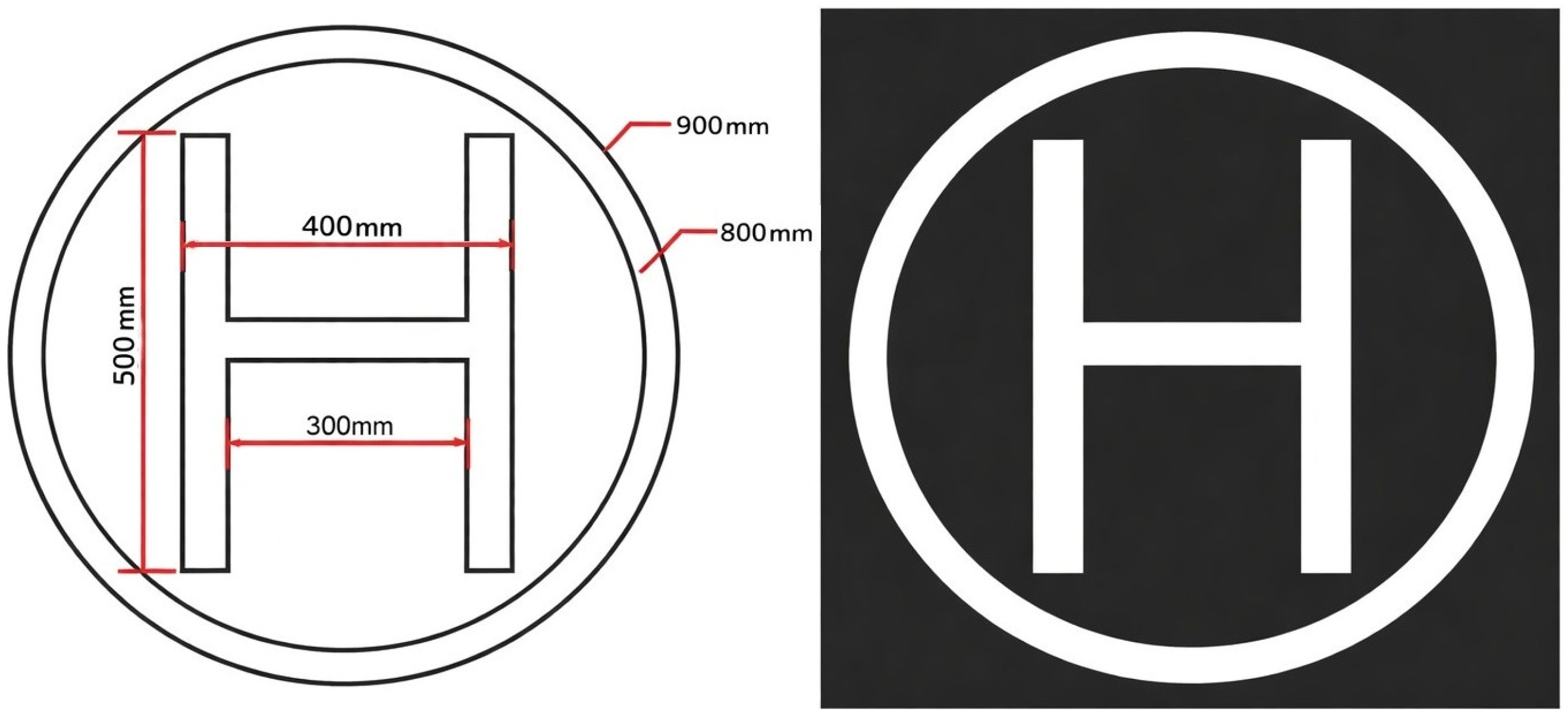
In our study, we used the helipad design shown in (
Figure 1)., which was used in the work of Lee et al. This design has a geometric helicopter landing pad shape defined in accordance with international standards. Furthermore, successful results were obtained in image processing and deep learning models. In our study, the helicopter landing pad was chosen as the landing symbol because it is easier and faster to recognise in optical awareness and image processing algorithms, and to define as a sharp point at fusion points.
3.2. Thermal Radiation and Emissivity
A black body is known as a perfect radiator, emitting all the energy it absorbs. The term “black body” was coined by Gustav Kirchhoff in 1860. In 1879, Josef Stefan found an experimental relationship between the power emitted by the black body per unit area and the temperature. A few years later, Ludwig Boltzmann derived this relationship theoretically.
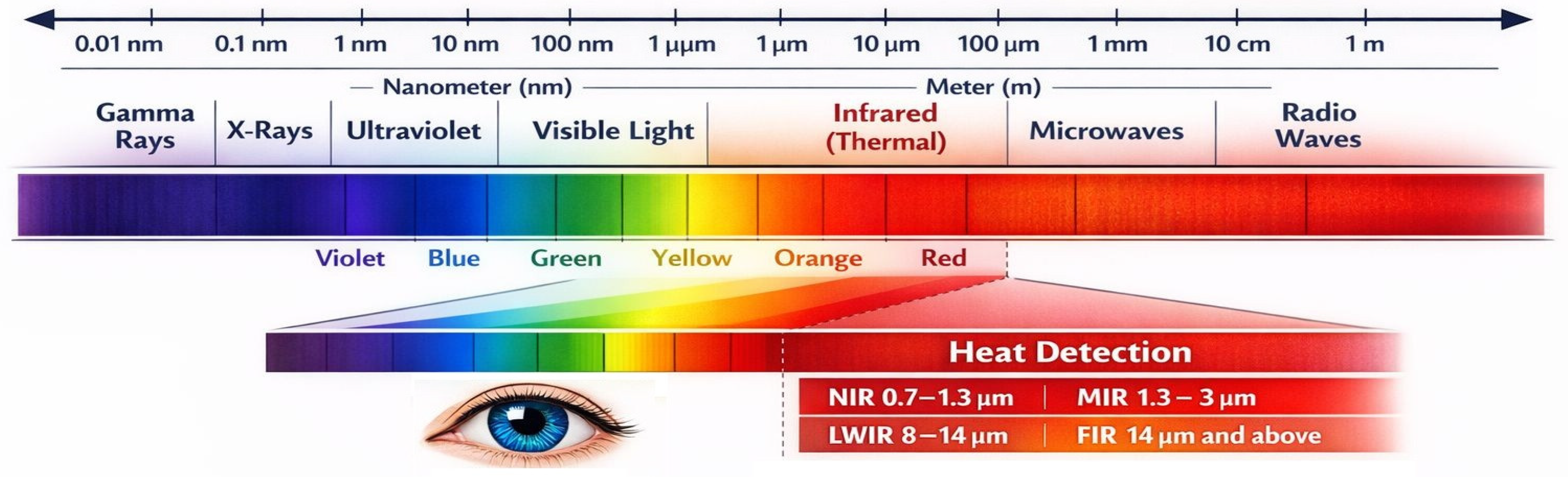
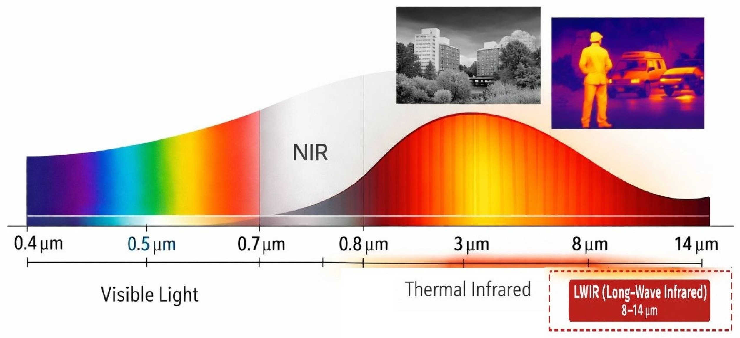
Blackbody radiation realises the Planck Spectrum, a spectral energy distribution that is characteristic and depends only on the temperature of the object. Every object with energy radiates. Infrared radiation is part of the electromagnetic spectrum and is a type of electromagnetic wave with wavelengths invisible to the human eye. Infrared radiation (IR) is often associated with heat energy and is used in many applications to detect temperature differences (
Figure 2).
With their technology, thermal camera sensors detect mainly infrared (IR) radiation but focus on a specific region of the IR spectrum. Infrared radiation lies just beyond visible light in the electromagnetic spectrum and has a wide range of wavelengths. From this broad spectrum, thermal cameras usually imaging using the far infrared (FIR) range [
48,
49].
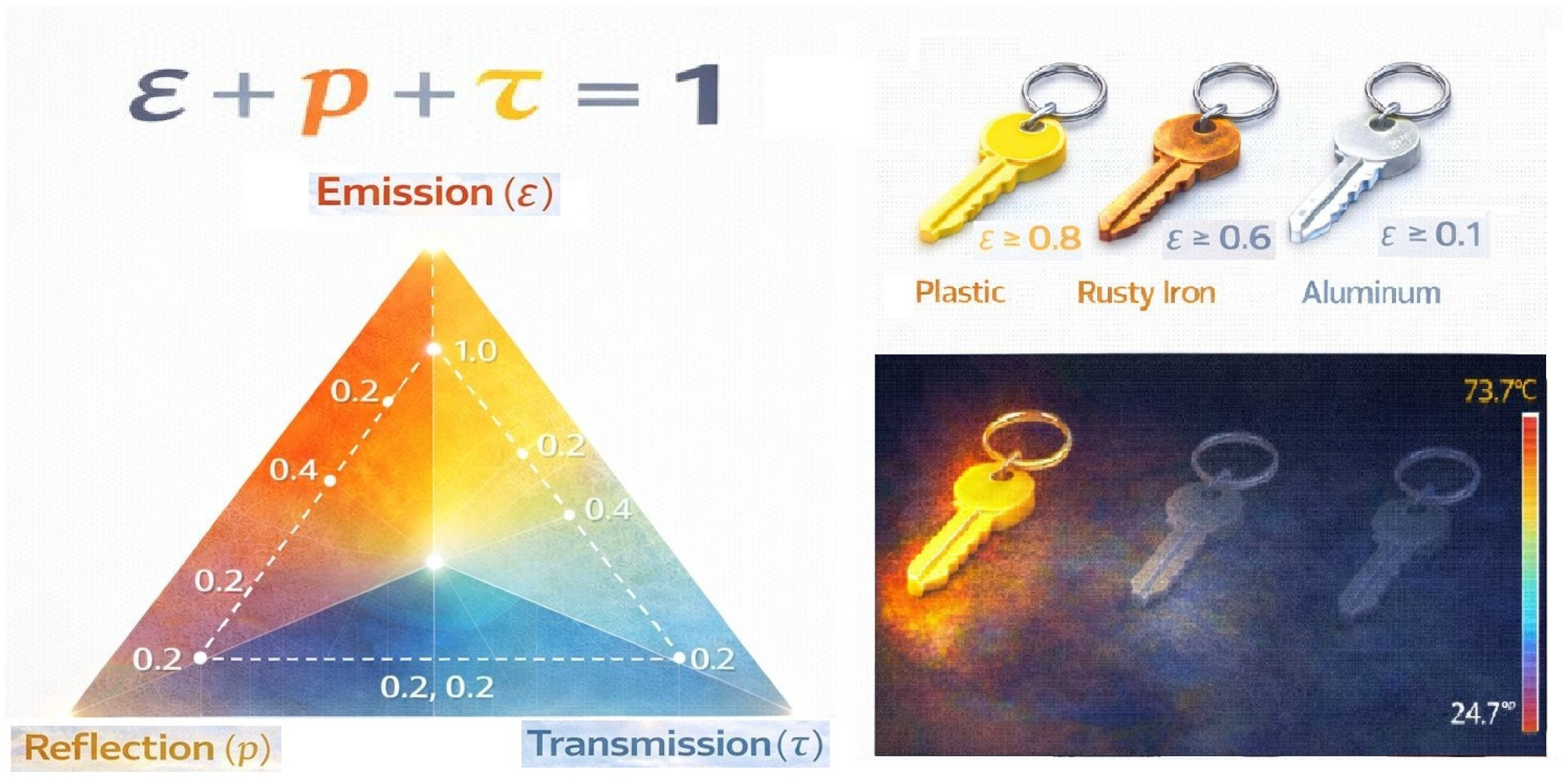
A key factor in the thermal camera’s image detection is emissivity. Emissivity is a dimensionless parameter ranging from 0 to 1 that defines a surface’s ability to emit energy in the infrared spectrum based on its thermodynamic temperature, and it directly determines the measurement accuracy of thermal imaging systems. Since thermal cameras detect radiant energy emitted from a surface and convert this information into a temperature value, the correct modelling of the surface’s actual emissivity value is of critical importance. High-emissivity surfaces provide more reliable and repeatable temperature measurements by minimising the effect of environmental reflections, while low-emissivity and reflective surfaces can negatively affect detection and classification performance by increasing measurement uncertainty. This situation is illustrated in (
Figure 3). In this context, the use of high-emissivity materials and coatings is widely recommended in the literature, particularly for aviation safety, night operations, and thermal-optical detection applications.
A measurement object with a high emissivity (ε ≥ 0.8)
A measurement object with an average emissivity (0.6 < ε < 0.8)
A measuring object with a low emissivity (ε ≤ 0.6)
3.3. Types of Thermal Camera
Thermal Cameras, depending on their type, can use part of the IR wave (
Figure 4).
Near Infrared (NIR) Wavelength: 0.7–1.3 micrometres
Middle Infrared (MIR) Wavelength: 1.3–3 micrometres.
Long Wave Infrared (LWIR) Wavelength: 8–14 micrometres
Far Infrared (FIR) Wavelength: 14 micrometres and above (usually down to 1 mm)
These sensors measure the IR radiation emitted from objects at different temperatures and convert it into electrical signals, which are then converted into a visual temperature map. These sensors are LWIR-MIR and NIR [
50].
Thermal UAVs have many positive effects on our lives. The fact that we can see and detect in dark environments and detect heat radionuclides with the thermal camera, without being dependent not only on natural or artificial light, gives us the opportunity to produce integrated solutions in our lives in many minimum and civilian solutions and detection [
51].
3.4. Computer Vision and YOLO
Computer vision systems (CVS) enable the automatic detection and classification of objects in images and videos using machine learning and deep learning techniques, most commonly convolutional neural networks (CNNs) [
52,
53,
54]. Among object detection algorithms, the YOLO (You Only Look Once) family stands out due to its real-time detection capability, high processing speed, and end-to-end single-stage architecture. YOLO models perform object detection by treating the task as a regression problem and predicting object classes and bounding boxes directly from the entire image in a single forward pass [
55].
Lee et al. demonstrated that YOLOv3 achieves superior detection speed compared to Faster R-CNN and SSD while maintaining high accuracy, thanks to its multi-scale detection capability, which enables effective detection of objects at different distances. Based on these findings and considering recent developments in UAV-based image analysis, this study utilises the YOLOv8 model, which offers improved mean average precision (mAP), faster inference, and enhanced performance in complex, real-time aerial imaging scenarios [
47,
52,
53].
YOLOv8 was selected due to its real-time detection capability, superior accuracy–speed trade-off, and proven effectiveness in UAV-based image analysis compared to alternative single-stage and two-stage object detection models [
56].
3.5. Image Fusions
Image fusion techniques can be used to provide rich environmental information by combining data from thermal camera images with optical camera images. These fusion methods have been tested to improve the effectiveness of deep learning models in thermal image processing, such as detail enhancement, target detection, noise reduction, and classification by processing thermal helipad images.
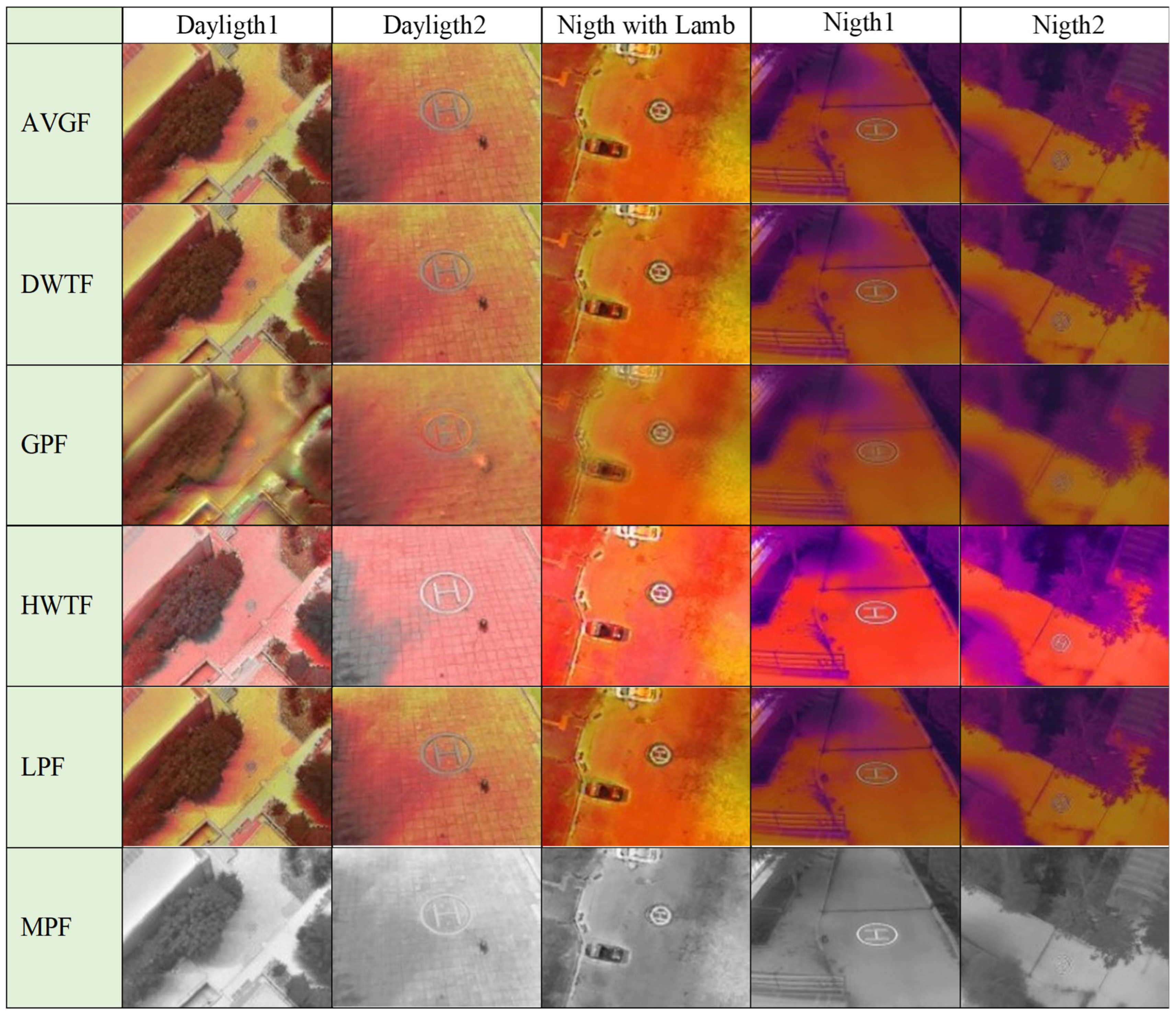
In this study, Averaging Fusion (AVGF), Discrete Wavelet Transform Fusion (DWTF), Gradient Pyramid Fusion (GPF), Laplacian Pyramid Fusion (LPF), Morphological Pyramid Fusion (MPF), and Haar Wavelet Transform Fusion (HWTF) methods were preferred.
The methods used in the fusion of thermal and optical images are differentiated according to approaches that prioritise different types of information. While simple methods such as AVGF offer computational advantages, they cannot sufficiently preserve the distinctiveness of thermal targets and optical details. Therefore, AVGF is generally used as a reference method for comparison purposes. More advanced approaches perform the fusion process by considering not only the intensity values of the images, but also their multi-scale and structural components [
57,
58].
DWTF, HWTF, and LPF methods aim to enhance the clarity of thermal targets and the continuity of optical textures by analysing images at different scales. In particular, DWTF and LPF produce successful results in terms of visual quality by ensuring a balanced transfer of both thermal contrast and optical details. Haar-based approaches are simpler and faster versions of these methods and are preferred in real-time and hardware-constrained systems [
59,
60,
61]. GPF and MPF focus on the structural and object-based features of the image. GPF provides advantages in applications where structural perception is critical, such as navigation and landing areas, by bringing edges and geometric boundaries to the foreground. MPF, on the other hand, preserves the shape integrity of thermal targets, increasing object continuity and offering a fusion that is more resistant to noise. In this respect, MPF is a prominent approach in object detection and thermal target-focused applications [
62,
63].
In this study, the preferred fusion methods were selected from among approaches that are widely accepted in the literature, suitable for comparative analysis, and capable of representing the complementary physical properties of thermal and optical images at different levels. Thermal images provide target clarity based on temperature differences, while optical images offer high spatial resolution and structural detail. The selected methods—specifically AVGF at the pixel level, DWTF and HWTF in multi-scale frequency analysis, GPF in structural and edge representation, LPF in detail–contrast balance, and MPF in object integrity—highlight different types of information, enabling a multifaceted evaluation of the effects of fusion. The combined use of these methods has made it possible to comparatively examine different performance criteria, such as thermal target emphasis, optical detail preservation, and structural continuity, rather than a singular approach focused solely on visual quality. Furthermore, the vast majority of these methods are classical fusion techniques that are parameter-independent, require no training, and can deliver consistent results under different scene conditions. This reduces the risk of overfitting the results to the dataset and increases their generalisability.
4. Materials and Methods
The overall workflow of the proposed system consists of three main stages: (1) thermal helipad generation using resistive heating, (2) optical and thermal dataset acquisition, and (3) YOLO-based detection using optical, thermal, and fused images.
Thermal UAVs have become frequently preferred in both minimum and civilian operations and problem-solving projects. Development of thermal helipads is considered important for thermal UAVs and vertical take-off and landing aircraft equipped with thermal cameras. It is crucial to provide pilots with meaningful and rapid data during landing to easily identify landing spots, especially under conditions of smoke, fog, pitch darkness, and overseas operations. Thermal imaging has been widely reported in the literature to provide improved scene perception under certain visibility-reducing conditions such as haze, smoke, and low illumination. With advancing technologies, it is possible for thermal helipads to be detected by thermal cameras and interpreted using computer vision algorithms. This development can be used in landing decision support systems. The combined use of thermal helipads and thermal cameras can provide effective visibility against potential accidents and risks.
4.1. Thermal Helipad Generation Using Resistive Heating
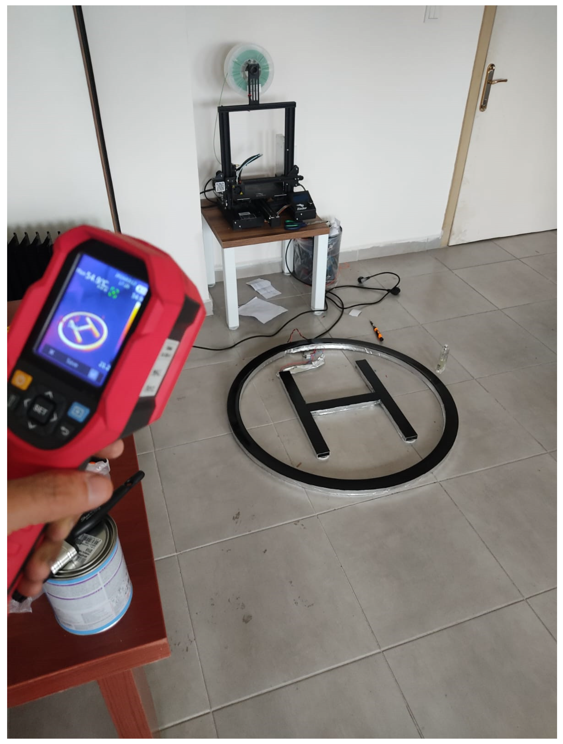
In this study conducted for a thermal helipad, the H and O symbols were shaped from 1 × 1 m–2 × 2 m metal aluminium sheets according to the specified dimensions and emissivity factor (
Figure 5 and
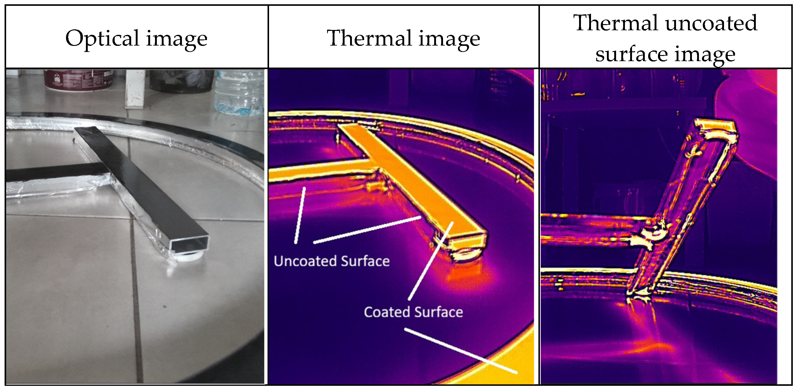
Figure 6). The helicopter landing pad-shaped plates were adjusted with special silicone resistors to reach specific temperature values. Thermal conductors were preferred for thermal heat distribution at the bonding points of the aluminium components and bonding silicone resistors. However, aluminium is a material with low emissivity and is therefore invisible to thermal cameras. To ensure that the aluminium plates are not directly visible on the thermal camera, they have been painted with black paint, which has a high emissivity value. This way, a helipad symbol has been obtained that has both uniform heat distribution and is easily visible on the thermal camera.
The thermal helipad heating time, temperature uniformity, power consumption, and environmental robustness can be further improved through engineering techniques. In our study, our helipad reaches 50 °C within 3 min and 70 °C within 5 min. There is a 250 Watt resistive silicon heater in the letter H and a 550 Watt resistive silicon heater in the letter O. Our Helipad is made of aluminium, a material that radiates heat evenly within itself. Aluminium has a low emissivity value. Even hot aluminium is not clearly visible on a thermal camera. Helipad surface coated with a black, plastic-based paint with a heat emissivity value of 0.95 or higher. This method creates a sharp clarity visible on the thermal camera on the Helipad symbol.
A basic measurement software that can be controlled and monitored on the DS18B20 microprocessor base with a temperature sensor on the landing plates on the helipads has been written. The temperature of the Helipad plates can be adjusted so that the software can gradually keep the Helipad between 20 and 70 °C.
4.2. Optical and Thermal Dataset Acquisition
In this study, the DJI Mavic 3T was used as the thermal UAV. After calibrating the thermal and optical lenses with the thermal UAV, exposures were collected at different angles and directions with vertical flights of 3–120 m and horizontal flights of up to 100 m. The DJI Mavic 3T’s dual sensor architecture ensures stable relative alignment between optical and thermal images during data acquisition. These exposure angles were captured in 10-s automatic photo mode while the thermal UAV was in motion. The dataset split was performed at the scene level to avoid potential data leakage between training, validation, and test subsets.
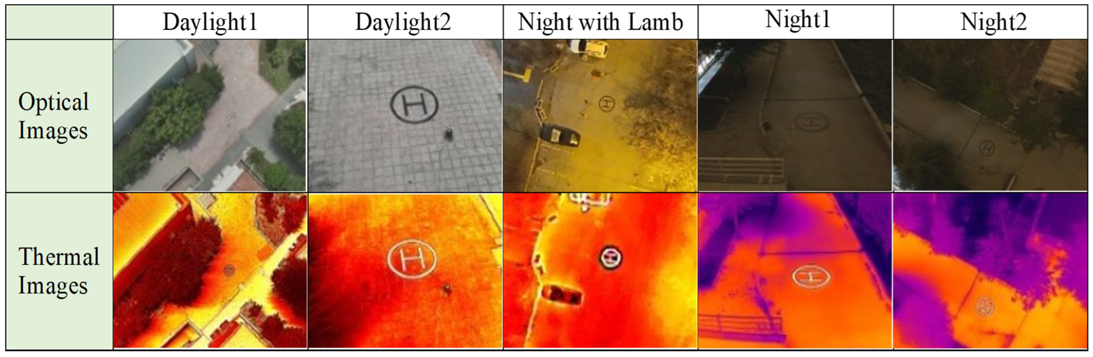
The dataset was collected across six different environments representing distinct scene backgrounds. Daytime, twilight, and night-time shots were taken separately, and the thermal camera’s night-time performance visibility on the helicopter landing pad was optimised. For our study, flights were conducted at six different locations and times to collect data. However, in our study, we proceeded by separating optical, thermal, and fusion images into their own categories rather than by spatial and temporal differences. Thermal, optical, and fusion images are uniquely distinct from one another during night, day, and twilight. Helipads constructed during the day, at night, and under night lighting have been tested with optical and thermal cameras (
Figure 7).
Additionally, to enhance the clarity of deep learning models on the thermal landing helicopter pad, the thermal landing area has been optimised to provide a more stable and clear image in terms of temperature and emissivity. Heat dissipation on the helipad has been ensured, particularly with the visible heat emission of the helipad sections. This has been achieved through the selection of materials that provide thermal conductivity and coating. Particularly in night-time footage, a clearly distinguishable helipad shape has emerged in the thermal camera compared to the optical camera.
In this study, the preferred fusion methods were selected from among approaches that are widely accepted in the literature, suitable for comparative analysis, and capable of representing the complementary physical properties of thermal and optical images at different levels. Thermal images provide target clarity based on temperature differences, while optical images offer high spatial resolution and structural detail. Data were acquired using the DJI Mavic 3T platform, which integrates optical and thermal sensors within a rigid dual-camera system. This integrated architecture ensures stable geometric alignment during flight. Minor spatial variations due to resolution and field-of-view differences were controlled through alignment verification and refinement prior to fusion. Paired optical and thermal frames were preserved at the flight-session level during dataset preparation to maintain modality consistency.
The selected methods—specifically AVGF at the pixel level, DWTF and HWTF in multi-scale frequency analysis, GPF in structural and edge representation, LPF in detail–contrast balance, and MPF in object integrity—highlight different types of information, enabling a multifaceted evaluation of the effects of fusion. The combined use of these methods has made it possible to comparatively examine different performance criteria, such as thermal target emphasis, optical detail preservation, and structural continuity, rather than a singular approach focused solely on visual quality. Furthermore, the vast majority of these methods are classical fusion techniques that are parameter-independent, require no training, and can deliver consistent results under different scene conditions. This reduces the risk of overfitting the results to the dataset and increases their generalisability. Different images were created using fusion techniques with optically and thermally matched images, which were then categorised and named (
Figure 8).
Optical and thermal data were combined using specified fusion methods. During fusion, shifts on the photogrammes were minimised by paying attention to image capture angles and lens optimisation.
4.3. YOLO-Based Detection Using Optical, Thermal, and Fused Images
Optical, thermal, and fusion images and labels were applied to 6968 images using the YOLO deep learning model. Firstly, to prevent potential data leakage, separate datasets were created using optical, thermal, and fusion images belonging to the same scene. Thus, the matched images obtained from the same acquisition session were not distributed across the training, validation, and test sets. To evaluate the YOLOv8 deep learning architecture, nine separate datasets comprising 6968 manually labelled images covering optical, thermal, and six different combined modalities were organised. When images were labelled for YOLO, images that could be considered overly similar and exposures that were very similar to each other were deleted to prevent overfitting during training. Optical and thermal datasets were split into 80% training, 10% validation, and 10% test data, and various learning studies were conducted on YOLOv8. We based the iteration count on 200 epochs, which was deemed sufficient for learning in tests conducted with validation data on the initial models created. This training depth was optimised to capture the complex spatial and thermal characteristics of helipad markers without risking overfitting, ensuring that the performance metrics (mAP, precision, and recall) accurately reflect the model’s robustness across diverse operational environments.
Training was conducted on the YOLOv8 Large model for our optical, thermal, fusion, and ALL (all of included) datasets, using batch_size: 8, imgsz: 640, dropout = 0.05. The models created afterwards have been named with the same names as the dataset clusters for comparison purposes.
Although thermal cameras have advanced in recent times, they produce lower resolution images compared to optical cameras. Fusion images created from the paired images of thermal and optical cameras can yield different and meaningful results. Processing thermal and optical data independently to learn the resulting difference using deep learning methods has enabled us to produce more stable results in terms of deep learning.
(
Figure 9) shows the number of images in the optical, thermal, and fusion datasets and the model training names. Tested the learned models with optically and thermally %10 validated data.
5. Results and Discussion
The results demonstrate that the nine models (O.pt, T.pt, AVGF.pt, GPF.pt, DWTF.pt, LPF.pt, MPF.pt, HWTF.pt, and ALL.pt) achieved high performance when evaluated on their respective validation datasets across optical, thermal, and fusion images (
Table 1), reflecting in-domain evaluation conditions.
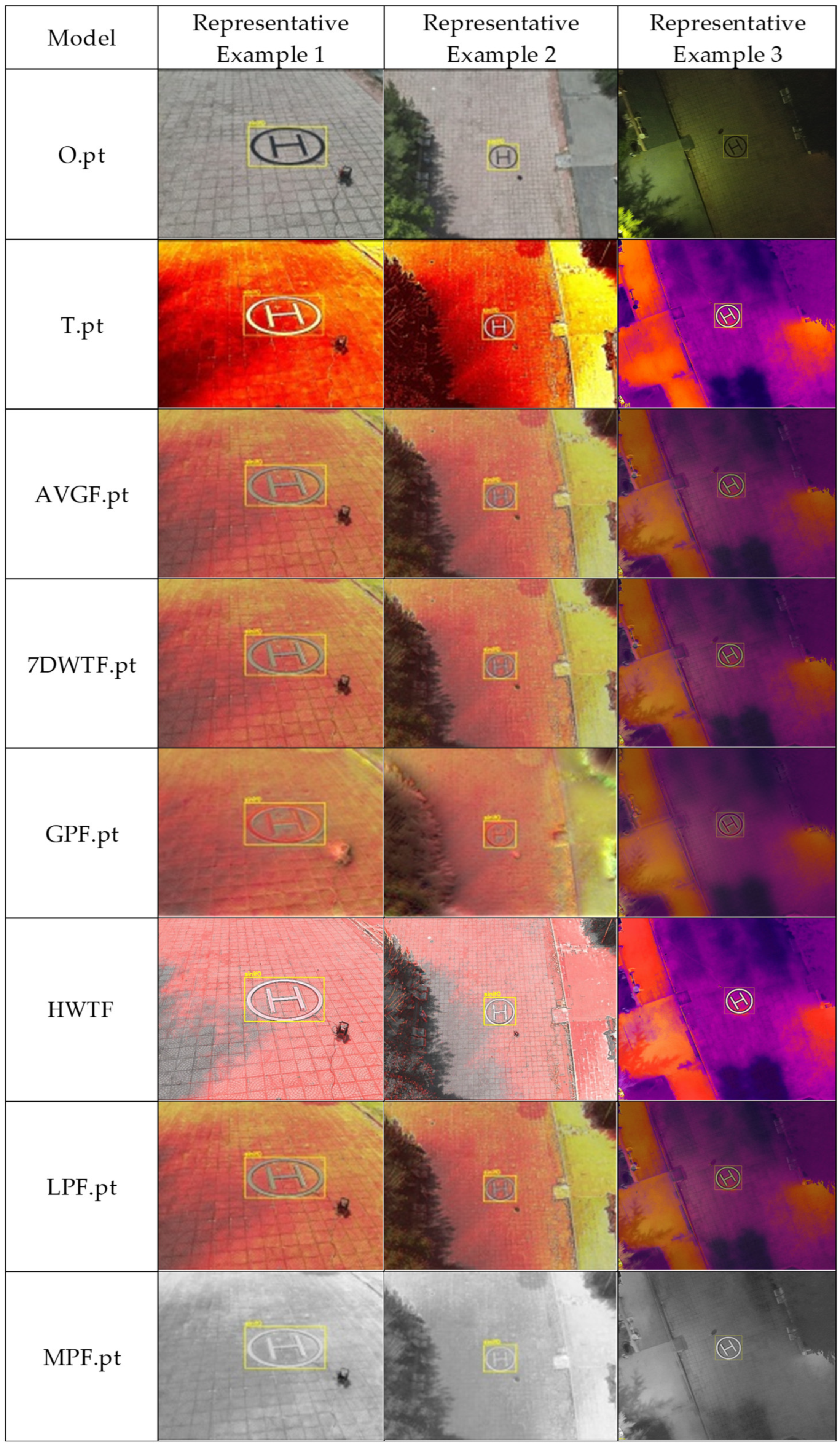
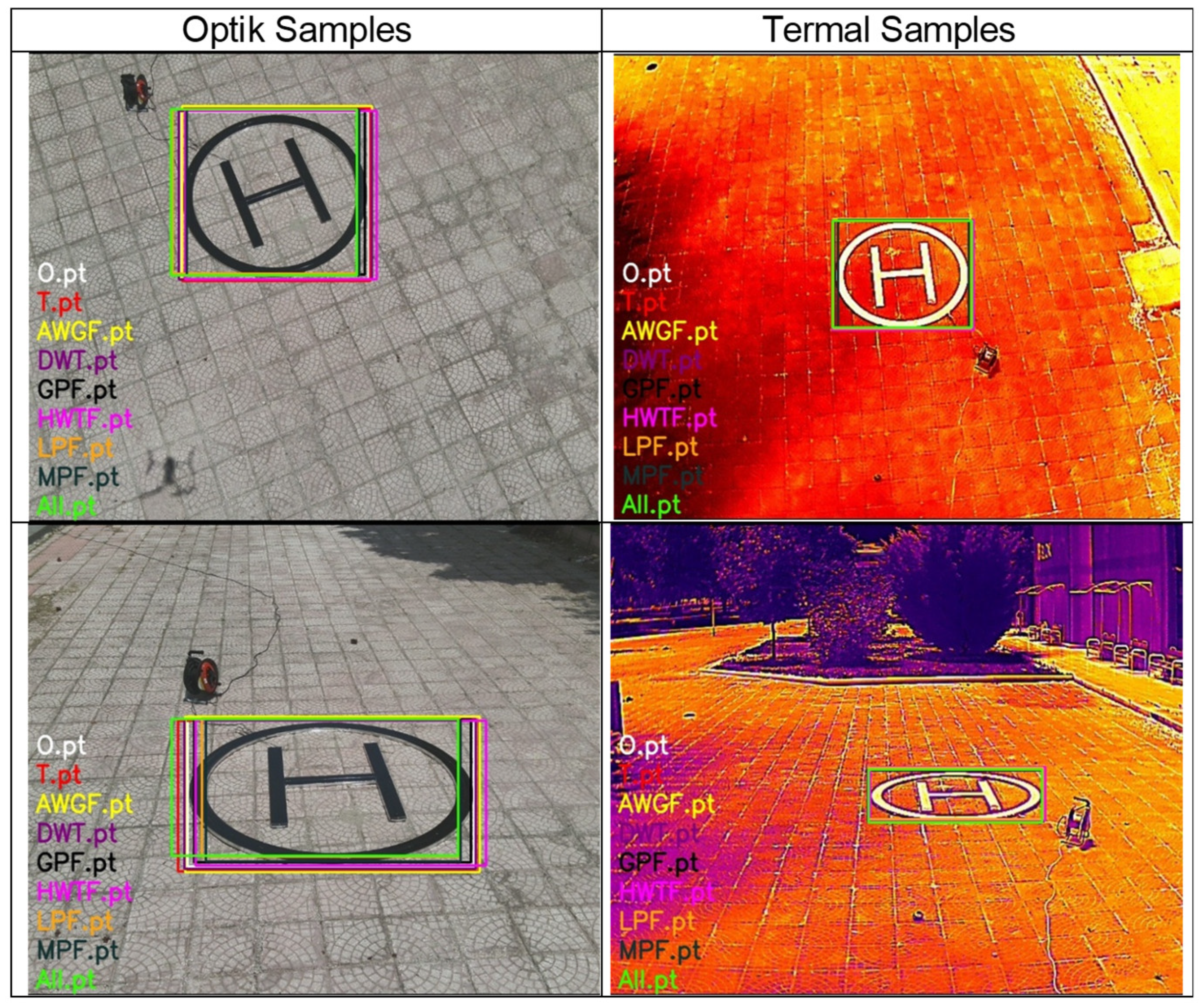
The relatively high metrics observed in the validation results can partly be attributed to the distinctive geometric structure of the helipad marker and the relatively consistent background conditions in the dataset. In addition, images captured within the same environment may allow the model to learn certain scene characteristics, which reduces the likelihood of false positive detections. As a result, the detection task becomes more structured compared to general object detection problems involving cluttered environments or multiple object classes. The learned models were run on optically and thermally separated data, and the success of the learning model using only fusion techniques was compared with optical and thermal data. It is shown in (
Figure 10).
(
Table 2) presents evaluation results on an independent daytime flight dataset collected in a separate session and excluded from both training and validation. (
Table 3) presents evaluation results on an independent night-time flight dataset collected under different environmental conditions.
6. Conclusions
This study presents a deep learning-based detection framework for UAV landing assistance using an actively heated thermal helicopter landing pad designed with resistant heating elements and a high-emission surface treatment. Experimental results show that optical and thermal data are affected by domain-specific limitations. Accordingly, it has been revealed that learning based on optical data is insufficient for evaluating thermal data, and similarly, learning based on thermal data does not sufficiently complete optical data with adequate accuracy. The objective of this study is to comparatively evaluate different trained models under identical experimental conditions rather than to claim absolute real-world generalisation performance. Therefore, the high in-domain metrics should be interpreted within the context of controlled validation scenarios and relative model comparison. The results presented in (
Table 3) highlight the detection performance obtained under night-time conditions, revealing the differences between optical, thermal, and fusion-based sensing approaches. In particular, optical-based detection becomes more challenging in night-time scenarios due to limited visible illumination. In contrast, fusion-based learning demonstrates improved robustness by leveraging complementary information from both thermal and optical modalities.
The findings show that the proposed thermally enhanced helipad can be reliably detected by UAV-mounted thermal cameras without relying on active infrared beacons or modulated IR sources. Fusion-based models, particularly those utilising LPF, HWTF, and MPF techniques, exhibited improved cross-domain generalisation, highlighting the effectiveness of multi-modal perception in degraded visual environments.
The findings indicate that thermal helipads can be reliably detected by thermal cameras mounted on UAVs. Fusion-based models, particularly those using LPF, HWTF, and MPF techniques, have shown improvement in generalisation between optical and thermal domains and emphasised the effectiveness of multi-modal detection in degraded visual environments.
Among the fusion methods LPF, HWTF, and MPF are relatively successful in both optical and thermal learning, whereas GPF is slightly weaker than the others. However, the fusion methods are quite successful at the threshold of these results.
Detection reliability decreases as altitude increases due to reduced pixel coverage of the helipad. The optical camera maintains sufficient spatial resolution at higher altitudes, while the thermal sensor resolution limits the number of pixels representing the target object. Nevertheless, larger helipad structures defined in national and international standards (e.g., helipad sizes of approximately 5 × 5 m within landing areas of about 10 × 10 m) may be detectable from significantly greater distances when higher-resolution thermal cameras are used. As thermal cameras become smaller, cheaper, and capable of producing relatively more meaningful data over time, they will be able to produce more meaningful and clearer results in night-time and pitch-dark environments and conditions. Furthermore, the development of computer vision and deep learning techniques and the increase in their application areas are enhancing both thermal camera solutions and the opportunities they bring.
The current study focuses on landing marker detection rather than a full precision landing control framework. Bounding box detection provides the initial localization of the landing marker and can serve as a precursor for downstream modules such as pose estimation or visual servoing in autonomous landing systems. In future UAV platforms, the integration of such detection systems with onboard navigation and control algorithms could enable more reliable autonomous landing assistance, particularly in low-visibility operational environments. However, the proposed method is validated under daytime, twilight, and night-time conditions. Its applicability to degraded visual environments such as fog or smoke is not experimentally evaluated in this study and remains part of future work.
Among the measures to be taken and applications to be developed for flight safety, thermal camera solutions may emerge as essential for future aeroplanes and helicopters. In this context, it is anticipated that the improvement of thermal data and the development of automatic detection systems equipped with artificial intelligence algorithms will reduce potential accidents and errors by giving pilots confidence in understanding and recognising airport runways and images of aircraft in the air. In adverse weather conditions such as fog, smoke, and pitch darkness, expanding pilots’ field of vision and obtaining clearer images by combining thermal and optical images may find its place among vision techniques that reduce the risk of accidents. The situation is similar for thermal UAVs. The development of thermal landing areas to quickly locate and identify landing areas for thermal UAVs, which are used in many projects and military operations, is considered crucial for the operational flight times and safe landings of thermal UAVs.
Author Contributions
Conceptualization, M.K., S.A.H. and E.D.; methodology, M.K., S.A.H. and E.D.; validation, M.K. and E.D.; investigation, M.K. and E.D.; resources, M.K. and E.D.; data curation, M.K. and E.D.; writing—original draft preparation, M.K. and E.D.; writing—review and editing, M.K., S.A.H. and E.D.; visualisation, M.K. and E.D.; supervision, M.K. All authors have read and agreed to the published version of the manuscript.
Funding
This work was supported by Research Fund of Erciyes University Scientific Research Projects (BAP) Coordination Unit under Project Number: FBA-2024-13687.
Data Availability Statement
The data set may be shared with qualified academic researchers for collaborative purposes, subject to approval by the corresponding author and compliance with institutional data sharing agreements.
Conflicts of Interest
The authors declare no conflicts of interest.
Abbreviations
The following abbreviations are used in this manuscript:
| UAV | Unmanned Aerial Vehicle |
| VTOL | Vertical Take-Off and Landing |
| EKF | Extended Kalman Filter |
| CNNs | Convolutional Neural Networks |
| YOLO | You Only Look Once |
| CVS | Computer vision systems |
| R-CNN | Region-based Convolutional Neural Network |
| SSD | Single Shot MultiBox Detector |
| GPS | Global Positioning System |
| GNSS | Global Navigation Satellite System |
| APAS | Advanced Pilot Assistance System |
| AVGF | Averaging Fusion |
| DWTF | Discrete Wavelet Transform Fusion |
| GPF | Gradient Pyramid Fusion |
| LPF | Laplacian Pyramid Fusion |
| MPF | Morphological Pyramid Fusion |
| HWTF | Haar Wavelet Transform Fusion |
| mAP | Mean Average Precision |
References
- Konar, M.; Hatipoğlu, S.A.; Akpınar, M. Improvement of UAV thrust using the BSO algorithm-based ANFIS model. Aeronaut. J. 2024, 128, 2364–2373. [Google Scholar] [CrossRef]
- Karaburun, N.N.; Hatipoğlu, S.A.; Konar, M. SOC estimation of Li-Po battery using machine learning and deep learning methods. J. Aviat. 2024, 8, 26–31. [Google Scholar] [CrossRef]
- Karaburun, N.N.; Hatipoğlu, S.A.; Konar, M. Aircraft takeoff speed prediction with machine learning: Parameter analysis and model development. Aeronaut. J. 2025, 129, 1534–1549. [Google Scholar] [CrossRef]
- Kekeç, E.T.; Konar, M.; Oktay, T. Investigation of the effect of thermal air flows on flight time and range of fixed-wing aerials. In International BILTEK Congress on Current Developments in Science, Technology and Social Sciences; İKSAD Publishing House: Ankara, Turkey, 2019; pp. 476–480. [Google Scholar]
- Turan, V.; Avşar, E.; Asadihendoustani, D.; Aydın, E.A. Image processing based autonomous landing zone detection for a multi-rotor drone in emergency situations. Turk. J. Eng. 2021, 5, 193–200. [Google Scholar] [CrossRef]
- Ünler, T. Development of battery-independent illumination drones integrated into tethered UAVs for extended operations. J. Mater. Mechatron. A 2024, 5, 250–262. [Google Scholar] [CrossRef]
- Nguyen Thuan, P.; Westerlund, T.; Peña Queralta, J. Vision-based safe autonomous UAV docking with panoramic sensors. Front. Robot. AI 2023, 10, 1223157. [Google Scholar] [CrossRef] [PubMed]
- Bektas, O.; Naundrup Pedersen, J.; Ramirez Gomez, A.; la Cour-Harbo, A. Automated emergency landing system for drones: SafeEYE project. In International Conference on Unmanned Aircraft Systems (ICUAS); IEEE: Piscataway, NJ, USA, 2020; pp. 1–8. [Google Scholar]
- Safadinho, D.; Ramos, J.; Ribeiro, R.; Filipe, V.; Barroso, J.; Pereira, A. UAV landing using computer vision techniques for human detection. Sensors 2020, 20, 613. [Google Scholar] [CrossRef] [PubMed]
- Wang, L.; Bai, X. Quadrotor autonomous approaching and landing on a vessel deck. J. Intell. Robot. Syst. 2018, 92, 125–143. [Google Scholar] [CrossRef]
- Mohammadi, A.; Feng, Y.; Zhang, C.; Rawashdeh, S.; Baek, S. Vision-based autonomous landing using an MPC-controlled micro UAV on a moving platform. In International Conference on Unmanned Aircraft Systems (ICUAS); IEEE: Piscataway, NJ, USA, 2020; p. 780. [Google Scholar]
- Wubben, J.; Fabra, F.; Calafate, C.T.; Krzeszowski, T.; Marquez-Barja, J.M.; Cano, J.C.; Manzoni, P. Accurate landing of unmanned aerial vehicles using ground pattern recognition. Electronics 2019, 8, 1532. [Google Scholar] [CrossRef]
- Badakis, G.; Koutsoubelias, M.; Lalis, S. Robust precision landing for autonomous drones: Combining vision-based and infrared sensors. In IEEE Sensors Applications Symposium (SAS); IEEE: Piscataway, NJ, USA, 2021. [Google Scholar]
- Liu, R.; Yi, J.; Zhang, Y.; Zhou, B.; Zheng, W.; Wu, H.; Cao, S.; Mu, J. Vision-guided autonomous landing of multirotor UAV on fixed landing marker. In IEEE International Conference on Artificial Intelligence and Computer Applications (ICAICA); IEEE: Piscataway, NJ, USA, 2020; pp. 1–5. [Google Scholar]
- Akhloufi, M.A.; Couturier, A.; Castro, N.A. Unmanned aerial vehicles for wildland fires: Sensing, perception, cooperation and assistance. Drones 2021, 5, 15. [Google Scholar] [CrossRef]
- Wing, M.G.; Burnett, J.D.; Sessions, J. Remote sensing and unmanned aerial system technology for monitoring and quantifying forest fire impacts. Int. J. Remote Sens. Appl. 2014, 4, 18–35. [Google Scholar] [CrossRef]
- Wiśnios, M.; Tatko, S.; Mazur, M.; Paś, J.; Łukasiak, J.M.; Klimczak, T. Identifying characteristic fire properties with stationary and non-stationary fire alarm systems. Sensors 2024, 24, 2772. [Google Scholar] [CrossRef]
- Becker, H.; Fernández, J. Unmanned aerial vehicles for disaster management. Int. J. Remote Sens. 2018, 39, 7654–7678. [Google Scholar]
- Sprague, J.P.; McCarthy, M.D.; Bay, J.C. A survey of UAV applications in search and rescue missions. J. Unmanned Veh. Syst. 2020, 8, 140–159. [Google Scholar]
- Burke, C.; McWhirter, P.R.; Veitch-Michaelis, J.; McAree, O.; Pointon, H.A.G.; Wich, S.; Longmore, S. Requirements and limitations of thermal drones for effective search and rescue in marine and coastal areas. Drones 2019, 3, 78. [Google Scholar] [CrossRef]
- Gonzalez, L.F.; Montes, G.A.; Puig, E.; Johnson, S.; Mengersen, K.; Gaston, K.J. Unmanned aerial vehicles and artificial intelligence revolutionizing wildlife monitoring and conservation. Sensors 2016, 16, 97. [Google Scholar] [CrossRef]
- Lyu, H.; Qiu, F.; An, L.; Stow, D.; Lewison, R.; Bohnett, E. Deer survey from drone thermal imagery using enhanced faster R-CNN based on ResNets and FPN. Ecol. Inform. 2024, 79, 102383. [Google Scholar] [CrossRef]
- Boczkowski, A.; Kuboszek, A.; Mańka, A.; Dutkiewicz, K.; Gramatyka, W.; Leśniak, A.; Stawinoga, E. Analysis of the possibility of using unmanned aerial vehicles and thermovision for the stocktaking of big game. Multidiscip. Asp. Prod. Eng. 2021, 4, 317–329. [Google Scholar] [CrossRef]
- Xie, Y.; Jiang, J.; Bao, H.; Zhai, P.; Zhao, Y.; Zhou, X.; Jiang, G. Recognition of big mammal species in airborne thermal imaging based on YOLOv5 algorithm. Integr. Zool. 2023, 18, 333–352. [Google Scholar] [CrossRef] [PubMed]
- Brebu, F.M.; Jianu, M.R.; David, V.; Bălă, A.C. Thermal imaging used in building thermal evaluation. Rom. J. Transp. Infrastruct. 2023, 12, 1–15. [Google Scholar] [CrossRef]
- Zhang, R.; Li, H.; Duan, K.; You, S.; Liu, K.; Wang, F.; Hu, Y. Automatic detection of earthquake-damaged buildings by integrating UAV oblique photography and infrared thermal imaging. Remote Sens. 2020, 12, 2621. [Google Scholar] [CrossRef]
- Chen, W.; Wei, K.; Wei, J.; Han, W.; Zhang, X.; Hu, G.; Wei, S.; Niu, L.; Chen, K.; Fu, Z.; et al. Research on the road performance of asphalt mixtures based on infrared thermography. Materials 2022, 15, 4309. [Google Scholar] [CrossRef]
- Escobar-Wolf, R.; Oommen, T.; Brooks, C.N.; Dobson, R.J.; Ahlborn, T.M. UAV-based assessment of concrete bridge deck delamination using thermal and visible cameras: A preliminary analysis. Res. Nondestruct. Eval. 2017, 38, 1–15. [Google Scholar]
- Foudeh, H.A.; Luk, P.C.-K.; Whidborne, J.F. An advanced UAV approach via learning-based control for overhead power line monitoring: A comprehensive review. IEEE Access 2021, 9, 130410–130433. [Google Scholar] [CrossRef]
- Sambhi, S. Thermal imaging technology for predictive maintenance of electrical installations in manufacturing plants: A literature review. In IEEE International Conference on Power Electronics, Intelligent Control and Energy Systems (ICPEICES); IEEE: Piscataway, NJ, USA, 2018. [Google Scholar]
- Kim, D.; Youn, J.; Kim, C. Automatic detection of malfunctioning photovoltaic modules using UAV thermal infrared images. J. Korean Soc. Surv. Geod. Photogramm. Cartogr. 2016, 34, 619–627. [Google Scholar] [CrossRef][Green Version]
- Messina, G.; Modica, G. Applications of UAV thermal imagery in precision agriculture: State of the art and future research outlook. Remote Sens. 2020, 12, 1491. [Google Scholar] [CrossRef]
- Hoffmann, H.; Nieto, H.; Jensen, R.; Guzinski, R.; Zarco-Tejada, P.; Friborg, T. Estimating evaporation with thermal UAV data and two-source energy balance models. Hydrol. Earth Syst. Sci. 2016, 20, 697–713. [Google Scholar] [CrossRef]
- Das, S.; Chapman, S.; Christopher, J.; Choudhury, M.; Menzies, N.; Apan, A.; Dang, Y.P. UAV thermal imaging for monitoring crop abiotic stress on sodic soils: A case study on wheat. Remote Sens. Appl. Soc. Environ. 2021, 23, 100583. [Google Scholar]
- Tsai, P.-H.; Huang, Y.; Tai, J.-H. Estimating soil water content from thermal images with an artificial neural network. Catena 2024, 241, 108029. [Google Scholar] [CrossRef]
- Matese, A.; Gennaro, S. Practical applications of a multisensor UAV platform in precision viticulture. Agriculture 2018, 8, 116. [Google Scholar] [CrossRef]
- Veneruso, P.; Manica, L.; Miccio, E.; Opromolla, R.; Tiana, C.; Gentile, G.; Fasano, G. FMCW radar-aided navigation for unmanned aircraft approach and landing in AAM scenarios. Sensors 2025, 25, 2429. [Google Scholar] [CrossRef]
- Skoczylas, M.; Walendziuk, W. Multiple camera-based real-time locating system for UAVs. In International Conference on Electrical and Power Engineering (EPE); IEEE: Piscataway, NJ, USA, 2018; pp. 193–198. [Google Scholar]
- Doer, C.; Koenig, R.; Trommer, G.F.; Stumpf, E. Autonomous Precision Takeoff and Landing System for VTOLs in Degraded Visual and GNSS-Denied Environments; Deutscher Luft- und Raumfahrtkongress: Bonn, Germany, 2020. [Google Scholar]
- Han, H. Visual navigation method for carrier-based aircraft landing. J. Phys. Conf. Ser. 2022, 2166, 012005. [Google Scholar] [CrossRef]
- Weis, M.J. Research and Development of a New Heliport Lighting System. Master’s Thesis, University of Tennessee, Knoxville, TN, USA, 1996. [Google Scholar]
- International Civil Aviation Organization (ICAO). Annex 14: Aerodromes, Volume I—Aerodrome Design and Operations; ICAO: Montreal, QC, Canada, 2023. [Google Scholar]
- Federal Aviation Administration (FAA). Helipad Design; U.S. Department of Transportation: Washington, DC, USA, 2023. [Google Scholar]
- Eurocontrol. Safety on Helipads; Eurocontrol: Brussels, Belgium, 2011. [Google Scholar]
- REG 13-36; Passenger Yacht Code: Annex 2—Technical Standards for Helicopter Landing Areas. Red Ensign Group (REG): London, UK, 2015.
- Directorate General of Civil Aviation (SHGM). Heliport Yapım ve İşletim Esaslarına İlişkin Talimat (SHT-Heliport); SHGM: Ankara, Turkey, 2022. [Google Scholar]
- Lee, S.; Jang, J.; Baek, K.-R. Implementation of vision-based real-time helipad detection system. In International Conference on Control, Automation and Systems; IEEE: Piscataway, NJ, USA, 2012. [Google Scholar]
- Loisel, H.; Jamet, C.; Riedi, J. Remote sensing. In Surface Ocean–Lower Atmosphere Processes; AGU: Washington, DC, USA, 2009; pp. 287–301. [Google Scholar]
- Alkinani, S.A. Study of Outgoing Longwave Radiation over Iraq Using AIRS Data. Master’s Thesis, Mustansiriyah University, Baghdad, Iraq, 2017. [Google Scholar]
- Gade, R.; Moeslund, T.B. Thermal cameras and applications. Health Inf. 2013, 17, 214–222. [Google Scholar]
- Vadivambal, R.; Jayas, D.S. Applications of thermal imaging in agriculture and food industry: A review. Food Bioprocess Technol. 2011, 4, 186–199. [Google Scholar] [CrossRef]
- Zoev, I.V.; Beresnev, A.P.; Markov, N.G. Convolutional neural networks of the YOLO class in computer vision systems. In I International Siberian Conference on Control and Communications (SIBCON); IEEE: Piscataway, NJ, USA, 2019. [Google Scholar]
- Lee, B.; Saj, V.; Kalathil, D.; Benedict, M. Intelligent vision-based autonomous ship landing of VTOL UAVs. arXiv 2022, arXiv:2202.13005. [Google Scholar] [CrossRef]
- Fung, J.; Mann, S. GPU-based image processing and computer vision. In IEEE International Conference on Multimedia and Expo; IEEE: Piscataway, NJ, USA, 2008; pp. 9–12. [Google Scholar]
- Redmon, J.; Divvala, S.; Girshick, R.; Farhadi, A. You only look once: Unified, real-time object detection. In IEEE Conference on Computer Vision and Pattern Recognition (CVPR); IEEE: Piscataway, NJ, USA, 2016; pp. 779–788. [Google Scholar]
- Hussain, M. YOLO-v1 to YOLO-v8, the rise of YOLO and its complementary nature toward digital manufacturing and industrial defect detection. Machines 2023, 11, 677. [Google Scholar] [CrossRef]
- Piella, G. A general framework for multiresolution image fusion: From pixels to regions. Inf. Fusion 2003, 4, 259–280. [Google Scholar] [CrossRef]
- Aslantas, V.; Bendes, E.; Toprak, A.N.; Kurban, R. Comparison of image fusion methods for surveillance applications. In International Conference on Imaging for Crime Detection and Prevention (ICDP); IEEE: Piscataway, NJ, USA, 2011. [Google Scholar]
- Li, S.; Kang, X.; Fang, L.; Hu, J.; Yin, H. Pixel-level image fusion: A survey of the state of the art. Inf. Fusion 2017, 33, 100–112. [Google Scholar] [CrossRef]
- Pal, A.R.; Singha, A. Comparative analysis of visual and thermal face image fusion. In IEEE International Conference on Imaging, Robotics and Intelligent Systems (IRIS); IEEE: Piscataway, NJ, USA, 2017; pp. 213–218. [Google Scholar]
- Blum, R.S.; Xue, Z.; Zhang, Z. An overview of image fusion. In Multi-Sensor Image Fusion and Its Applications; CRC Press (Taylor & Francis): Boca Raton, FL, USA, 2018; pp. 1–36. [Google Scholar]
- Sharma, A.M.; Dogra, A.; Goyal, B.; Vig, R.; Agrawal, S. From pyramids to state-of-the-art: A comparison of visible–infrared image fusion techniques. IET Image Process. 2020, 14, 1671–1689. [Google Scholar] [CrossRef]
- Sadjadi, F. Comparative image fusion analysis. In IEEE Conference on Computer Vision and Pattern Recognition; IEEE: Piscataway, NJ, USA, 2005. [Google Scholar]
| Disclaimer/Publisher’s Note: The statements, opinions and data contained in all publications are solely those of the individual author(s) and contributor(s) and not of MDPI and/or the editor(s). MDPI and/or the editor(s) disclaim responsibility for any injury to people or property resulting from any ideas, methods, instructions or products referred to in the content. |