1. Introduction
In recent years, research on aerial robots for physical interaction tasks has expanded rapidly, with a particular focus on multirotor aerial vehicles (MRAVs). These platforms provide fast access to high-altitude or hard-to-reach workspaces, reducing time, cost, and risks to human workers in inspection and maintenance scenarios [
1]. However, such applications demand precise and stable physical interaction, which has driven advances in MRAV design and interaction control architectures.
Conventional quadrotors, with coplanar and collinear propellers, are underactuated: thrust and torque cannot be independently commanded along all 6 degrees of freedom (DoF). As a result, horizontal flight or lateral force exertion requires body tilting, coupling position and attitude dynamics, and limiting dexterity [
2]. A common path to restore decoupled control is to adopt fully actuated bases. Current fully actuated designs follow two main paradigms: actively tilting propellers (morphing platforms) and fixedly tilted propellers with distinct rotor orientations. Representative examples include overactuated tiltable platforms [
3,
4] and fixed-tilt omnidirectional vehicles with reversible thrust or non-coplanar layouts [
5,
6]. Recent surveys comprehensively review these families and their control-allocation properties. In [
7], modeling and control approaches for physically interactive aerial vehicles, including multirotors, are reviewed. The work in [
8] surveys and categorizes the different types of physical interactions that have been demonstrated with MRAVs. Furthermore, [
9] reviews fully actuated MRAVs and classifies them according to their actuation characteristics.
For physical interaction, admittance control is preferred over impedance when accurate trajectory tracking in free flight must be preserved while bounding contact forces; it separates motion control from interaction behavior [
10]. Moreover, on fully actuated platforms, contact-based inspection and robust interaction policies have been demonstrated, highlighting practical controller choices under interaction uncertainty. For instance, ref. [
11] demonstrates point contact and sliding using impedance and direct force control on an omnidirectional MRAV with tiltable rotors. Similarly, ref. [
12] employs a passivity-based Port-Hamiltonian approach to reshape the apparent impedance and admittance properties of a fully actuated hexarotor. Sensorless approaches avoid additional force/torque (FT) sensors by exploiting acceleration- or momentum-based observers [
13]. At the same time, modeling and simulation choices for contact and friction can strongly influence interaction stability; see recent comparative analyses [
14].
Implementing sensorless admittance control on fixedly tilted non-planar omnidirectional platforms (NPFTPs) is challenging. Mutual aerodynamic interference alters the effective thrust produced by one rotor due to flow interactions with neighbors, degrading quadratic thrust models and biasing wrench observers.
While a recent omnidirectional MRAV design, proposed in [
15], may mitigate these effects by optimizing the propeller position and orientations to avoid mutual interference, such interactions remain unavoidable in many designs. For example, the design proposed in [
5], in which rotors are placed at the vertices of a cube and their orientations are optimized to maximize the vehicle’s agility inherently suffers from aerodynamic coupling between rotors.
In [
16], a method that adapts the thrust coefficient based on the orientations, positions, and rotational speeds of neighboring propellers to account for aerodynamic cross-interactions is introduced. Although promising, this method requires force–torque sensors on all propellers and extensive parameter identification, making it potentially impractical. In [
17], a method to identify the wrench map from free-flight experiments is proposed, thereby avoiding the need for FT sensors to measure the rotor wrench; however, this approach does not yield improved tracking accuracy and is not applied for omnidirectional maneuvers.
Although the flying end-effector paradigm has been experimentally validated for planar non-collinear fixedly tilted propeller (NCFTP) platforms [
18], robust application to NPFTP platforms requires addressing interference-induced model errors. In this work, we present, to the best of our knowledge, the first experimental implementation of an admittance-filter-based physical interaction controller on an omnidirectional NPFTP MRAV subject to mutual aerodynamic interference. We utilize the Omnirotor, a platform inspired by a prior omnidirectional design [
19], which itself builds upon earlier work by [
5].
To mitigate interference-driven modeling errors, we identify piecewise linear wrench maps directly from free-flight data and use them in constrained control allocation. Our approach complements existing taxonomy and allocation formulations [
20] and aligns with recent system identification efforts for fully actuated UAV allocation [
17]. Extensive experiments—point contact at various orientations, sliding along a curved surface, and peg-in-hole—demonstrate stable interaction and improved contact maintenance under large attitude variations. These advances complement controller designs validated in contact-rich scenarios on tiltable/fully actuated MAVs [
11,
12].
This paper is organized as follows: In
Section 2, the dynamic model of the Omnirotor is reviewed. In
Section 3, the proposed novel input allocation method is detailed. In
Section 4, the control architecture used for physical interaction is covered. In
Section 5, the experimental campaign demonstrating omnidirectional physical interaction is presented. Finally, in
Section 6, the results and outline of future work are discussed.
2. Dynamical Model
This section recalls the model of the Omnirotor vehicle [
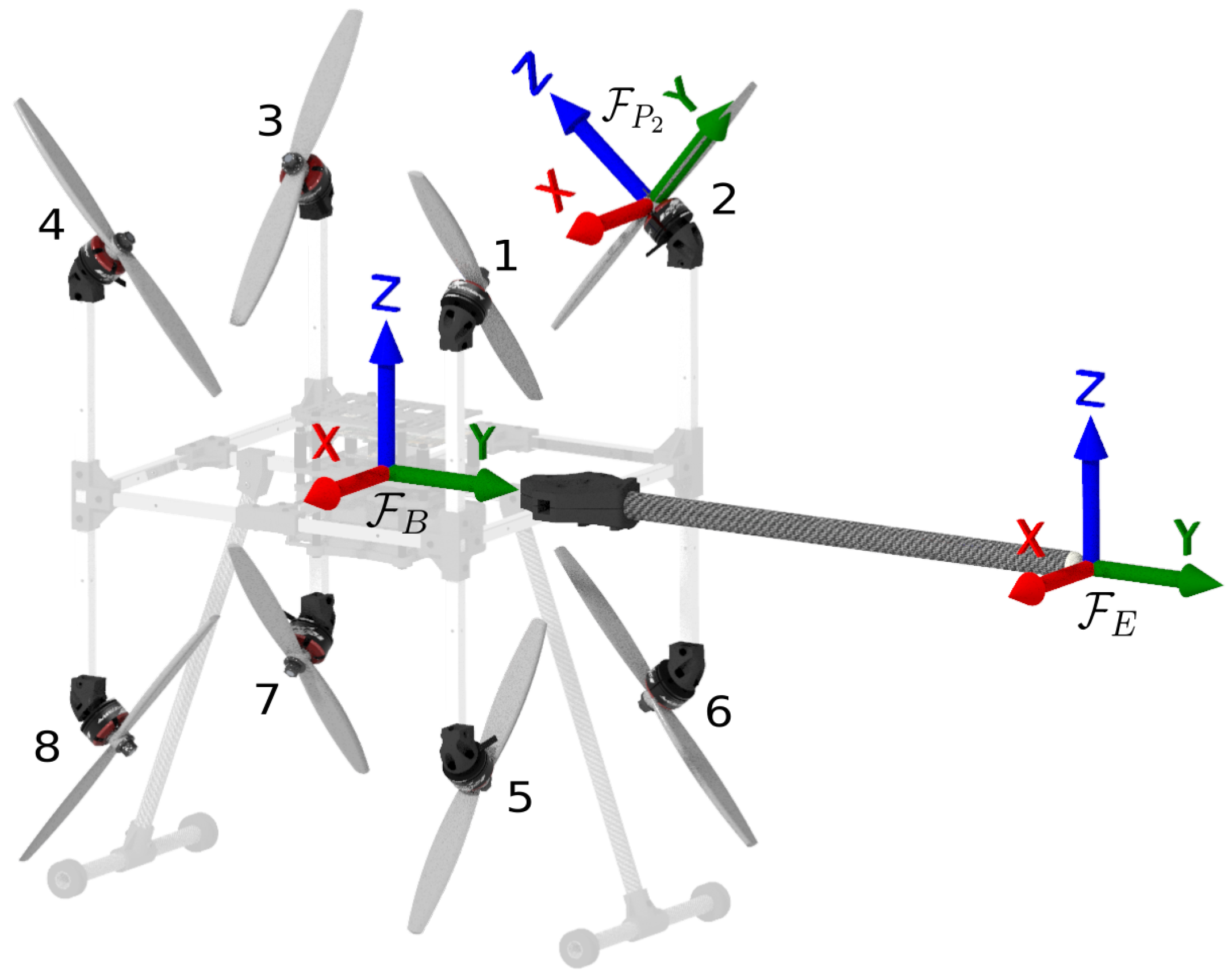
19]. The Omnirotor, shown in
Figure 1, consists of eight bidirectional propellers placed at the vertices of a cube of side length
[m] centered at the center of mass (CoM), at which frame
is attached. We denote by
,
, and
the world frame, the end-effector frame attached at the tool tip, and propeller’s
i frame attached at its center, respectively. The rotation matrix from
to
is given by
,
and
,
, where the sign sequence is
;
is the elementary rotation about axis ∗. We have
, for which the platform is omnidirectional [
19].
The robot is modeled as a rigid body in free space where the translational and rotational dynamics are described by the Newton–Euler equations
where
is the inertia tensor of the rigid body;
and
are the body angular velocity and the inertial position of the CoM, respectively;
m is the system’s mass;
g is the gravity acceleration;
and
are the external force and moment applied to the robot via the end-effector;
and
are the force and moment input applied to the robot via the rotors. The propeller’s
i force and drag torque are respectively
, see [
20], where
are the thrust and drag coefficients, respectively.
is its rotational speed along the
axis, whereas
is determined by the propeller’s blade configuration. Each propeller produces a moment
at the CoM.
According to this nominal model which will be used for the control and estimation, the actuation wrench is thus represented by the linear wrench map , with denoting the full-rank wrench allocation matrix and being the input.
3. Piecewise Linear Wrench Map Identification
The accuracy of the linear wrench map—standard in multirotor control—is often compromised by manufacturing tolerances and, more critically, by mutual aerodynamic interference. The Omnirotor is particularly susceptible to the latter due to its non-coplanar propeller configuration. While this geometry enables omnidirectionality, it induces significant aerodynamic cross-coupling that attenuates the effective thrust [
16,
19].
Crucially, these modeling errors are not static; they vary with the vehicle’s attitude. Maintaining different orientations requires specific combinations of rotor speeds and direction reversals, which in turn alter the airflow interactions and the resulting interference patterns. Consequently, a single constant linear wrench map cannot accurately capture the platform’s behavior across its full flight envelope. Conversely, deriving a fully nonlinear aerodynamic model is impractical, as it would require identifying a prohibitive number of parameters with uncertain real-world robustness.
3.1. Proposed Strategy
To balance accuracy and tractability, we propose approximating the inherently nonlinear system using a piecewise linear wrench map. We partition the attitude space (specifically, the sphere representing gravity directions in the body frame) into distinct regions. For each region, we identify a specific local linear wrench map that is refined from the nominal model using experimental data collected within that region. This allows the controller to switch or interpolate between locally accurate linear models rather than relying on a single, globally comprised approximation.
3.2. Data Acquisition Protocol
To identify these local maps, we employ a hovering-based data collection strategy. The objective is to record the actual control inputs required to sustain specific orientations, thereby capturing the aerodynamic reality of those operating points.
We command the vehicle to hover at a steady-state orientation
. In this condition, the external wrench exerted on the body is dominated by gravity. We record the wrench
applied at the Center of Mass (CoM):
where
denotes the block-diagonal matrix operator, which constructs a matrix with the given arguments on its main diagonal and zeros elsewhere. Simultaneously, we record the corresponding propeller input matrix
needed to counteract this weight. This yields a data pair
for the
j-th measurement.
Assumptions and limitations: This protocol assumes that the aerodynamic interference observed at hovering thrust levels scales acceptably to other thrust levels within the region. A limitation of this approach is that it relies on gravity as the ground truth force; consequently, the net torque is zero during data collection, and the force magnitude is fixed at . However, since the primary source of error is thrust attenuation due to rotor-to-rotor interference (rather than torque induction), our experiments demonstrate that identifying the force mapping at operating weight substantially improves performance across the interaction envelope.
3.3. Identification Algorithm
We compile a dataset of
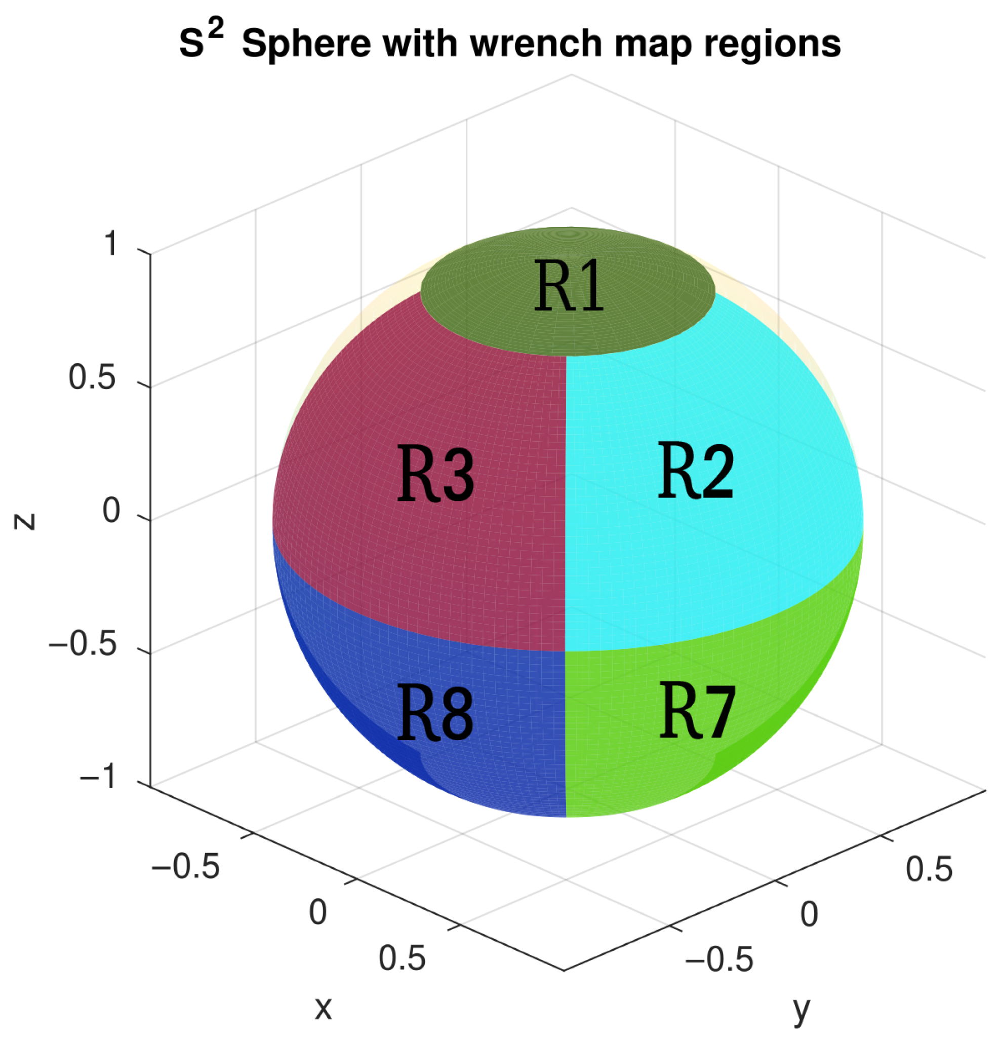
n measurements and cluster them according to the regions of competence defined on
(see
Figure 2). In this work, we collect 15 measurements per region. Body orientations,
, are sampled randomly from the corresponding region to ensure good coverage of thrust vectors in the whole region. For each region, we solve for the optimal wrench allocation matrix
by minimizing the error between the predicted and observed wrench, while constraining the solution to remain physically close to the nominal theoretical model.
The regions are selected heuristically. It is observed that in these regions, the platform typically exhibits similar propeller patterns, with some propellers operating at positive speeds and others at negative speeds. Consequently, attitudes in these regions are assumed to have a similar aerodynamic interference pattern.
The identification is formulated as the following Quadratic Programming (QP) problem:
where
is the aggregated input matrix;
is the aggregated wrench vector;
is a weighting matrix;
and ;
is the vectorization of the target allocation matrix;
is the vectorization of the nominal allocation matrix derived from geometric and isolated blade parameters;
sets the permissible deviation bounds. For our experiments, we set .
3.4. Allocation Matrix Validation
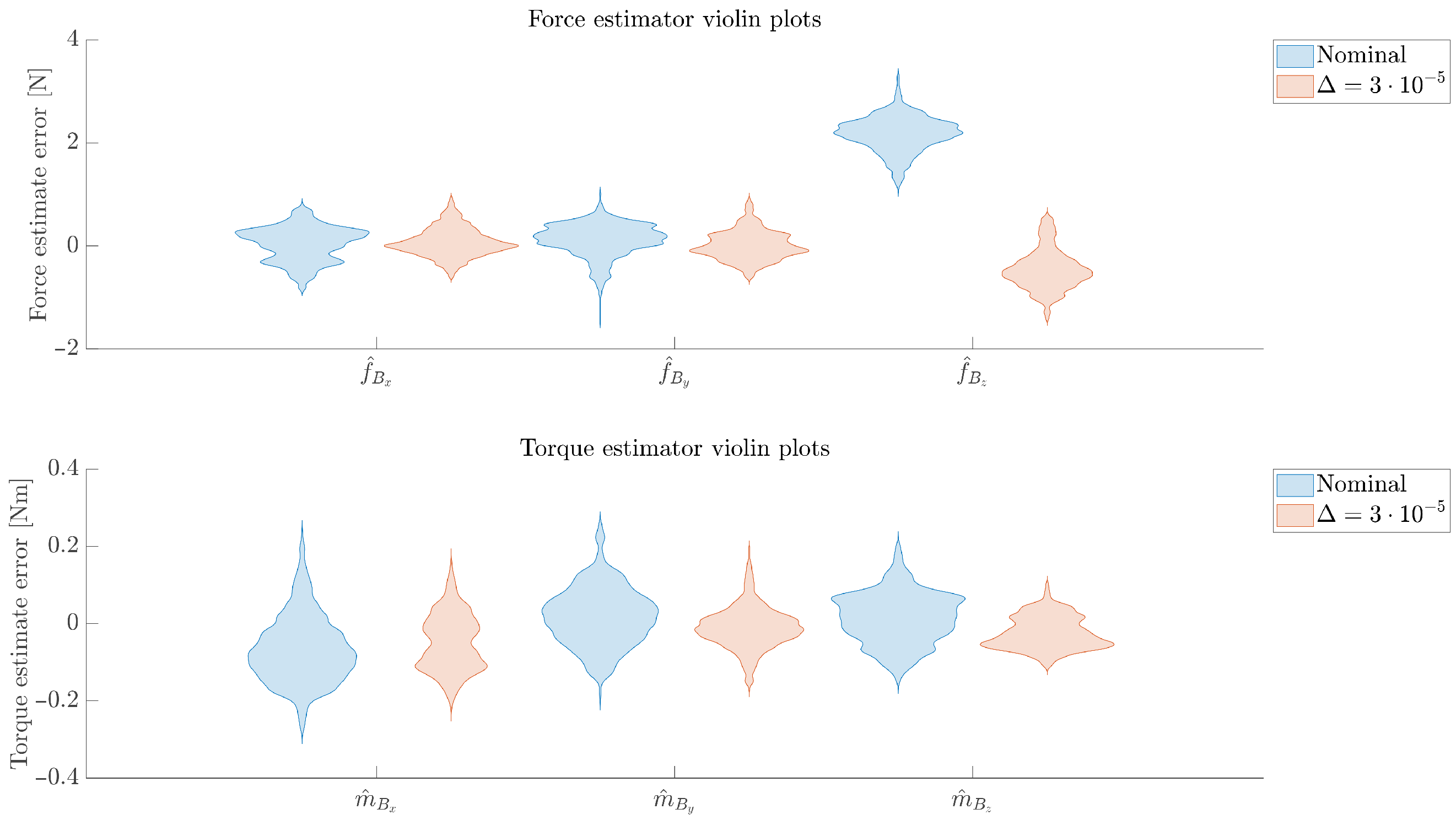
To quantitatively assess the performance of the wrench observer and validate the optimized allocation matrix for a given region, we analyze the estimated external wrench during free flight. The vehicle is commanded to hover for 5 [s] at five randomly selected orientations within this region, and the estimated external wrench is recorded. Since no physical interaction occurs during hovering, the true external wrench is expected to be zero.
In
Figure 3, violin plots of the estimated wrench are shown. When using the nominal allocation matrix, a bias of approximately
[N] is observed in the estimated force along the thrust direction, indicating modeling inaccuracies in the nominal allocation matrix due to propeller interactions. Any bias is almost completely eliminated when using the optimized allocation matrix with
. Furthermore, the variance in the estimated torque components is reduced, indicating improved consistency and reduced estimation noise.
3.5. Evaluation Framework
To validate the efficacy of the piecewise approach, we also compute a “Global Optimized” map by running the optimization (
3) over the entire dataset (treating the full sphere as a single region). We hypothesize that while the Global Optimized map will outperform the nominal model, the piecewise linear approach will yield superior tracking and interaction performance by accounting for the attitude-dependent nature of the aerodynamic interference.
5. Experimental Investigation
To validate the omnidirectional physical interaction capabilities of the proposed system, we conducted a series of experiments. First, we demonstrate a point-contact task to verify the system’s ability to exert precise forces (with magnitudes up to ≈25% of the MRAV’s weight) on surfaces of varying orientations while maintaining stable, non-oscillatory behavior. Second, we perform a sliding experiment to assess the feasibility of stable, continuous interaction on highly curved geometries, specifically a cylindrical surface. Finally, we execute a challenging peg-in-hole task to highlight the system’s attitude compliance and stability under complex end-effector constraints. The Root-Mean-Square (RMS) and max trajectory tracking errors for these experiments are reported in
Table 1. Video of all performed experiments can be found in the
Supplementary Materials.
The platform possesses a mass of
[kg] and an inertia tensor
[
]. The end-effector is located at
[m] relative to the CoM. The wrench observer utilizes gains
and
. Furthermore, the estimated wrench signal is low-pass-filtered with a cut-off frequency of 10 [Hz]. The admittance filter parameters employed for each specific experiment are detailed in
Table 2. The pose controller gains remain constant across all experiments:
,
,
,
, and
. The software architecture is implemented using the TeleKyb3 (
https://git.openrobots.org/projects/telekyb3 (accessed on 5 February 2026)) framework, which provides modular components for control, state estimation, and middleware integration.
For practical deployment, the admittance filter parameters must be tuned based on the task at hand. A manufacturer may develop a predefined set of parameters for different operational scenarios, such as free flight, sliding contact, or peg-in-hole. A single parameter set associated with a given flight mode can be applied across a wide range of operating conditions. For instance, in point-contact or sliding tasks, the desired EE position can be commanded slightly inside the contact surface with a specified penetration depth to achieve the required steady-state interaction force. In practice, the admittance parameters can thus be tuned by the manufacturer to ensure sufficient robustness against external disturbances, such as wind and friction, which manifest as estimated external forces that cause deviations from the nominal trajectory and can be regulated primarily through virtual stiffness tuning, . Furthermore, the second-order system dynamics can be tuned to ensure a smooth contact transition without bouncing at a given approach velocity. The desired interaction force (e.g., a required contact pressure for a specific sensor) can then be regulated online by modifying the penetration depth of the reference trajectory in real time. In this case, the virtual stiffness, , was tuned to achieve a desired displacement at a given steady-state wrench. The remaining parameters are selected to ensure that the resulting second-order system is critically damped.
5.1. Point Contact
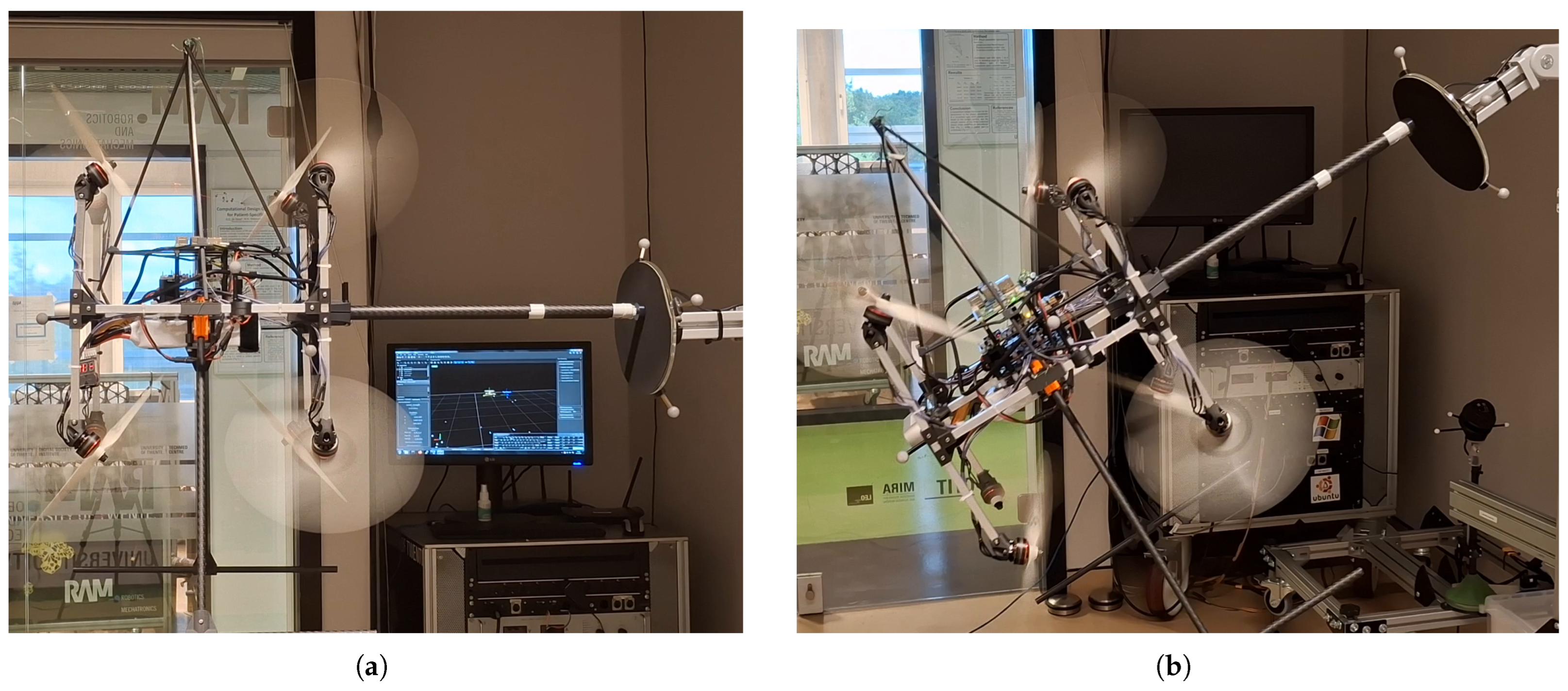
In
Figure 5, the MRAV’s end-effector (EE) maintains contact with a straight and tilted surface in a single static point. In the straight surface tests, the normal to surface, i.e.,
z-axis of the surface frame
, is aligned with the
y-axis of the world frame, whereas in the tilted surface tests, it is inclined downward by
. The end-effector is first aligned with the surface normal, then slowly tilted by ±
in roll, pitch, and yaw while maintaining contact, highlighting the ability to reorient the tool after contact. To accurately measure the interaction forces, the surface is attached to an ATI Mini 40 Force-Torque sensor (
https://www.ati-ia.com/products/ft/ft_models.aspx?id=Mini40 (accessed on 5 February 2026)), serving as a ground truth of the interaction forces. The point-contact experiments are performed with a single linear wrench map using the nominal allocation matrix.
5.1.1. Straight Surface Contact
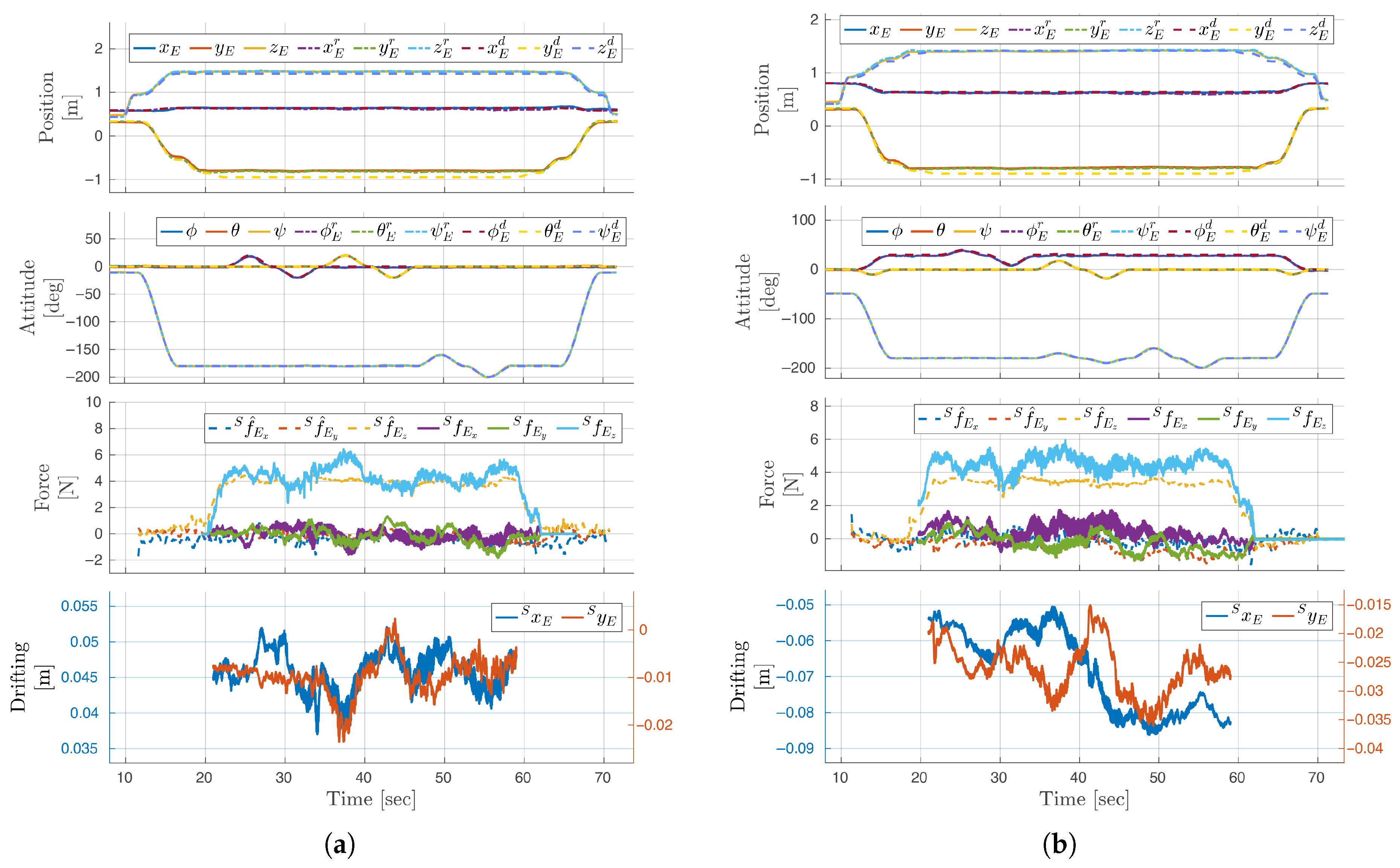
Figure 6a shows the position plots displaying how the compliant
y-axis reference trajectories are followed as a response to external forces along the world-frame
y-axis. While the system is in contact, the tilting is performed as shown in the attitude plot. The transition from contact-free to contact flight occurs with no excessive impact force. The computed end-effector position in the xy-plane of the surface frame is also plotted, illustrating how the end-effector drifts during contact. The observed sliding is moderate, approximately 1–2 [cm] in both the x- and y-directions, and primarily occurs when the end-effector is actively tilting.
5.1.2. Tilted Surface Contact
The results of the tilted point contact are shown in
Figure 6b. Similar to the straight surface point contacts, the transition from contact-free to contact flight is handled smoothly. In contrast, the normal force is underestimated by
[N], a consequence of using the nominal allocation matrix. This effect is more evident in the sliding contact due to requiring a large-angle maneuver, which is why the wrench map identification method is employed for the sliding task. Also, more drifting is observed of 2–3 [cm].
5.2. Sliding Contact
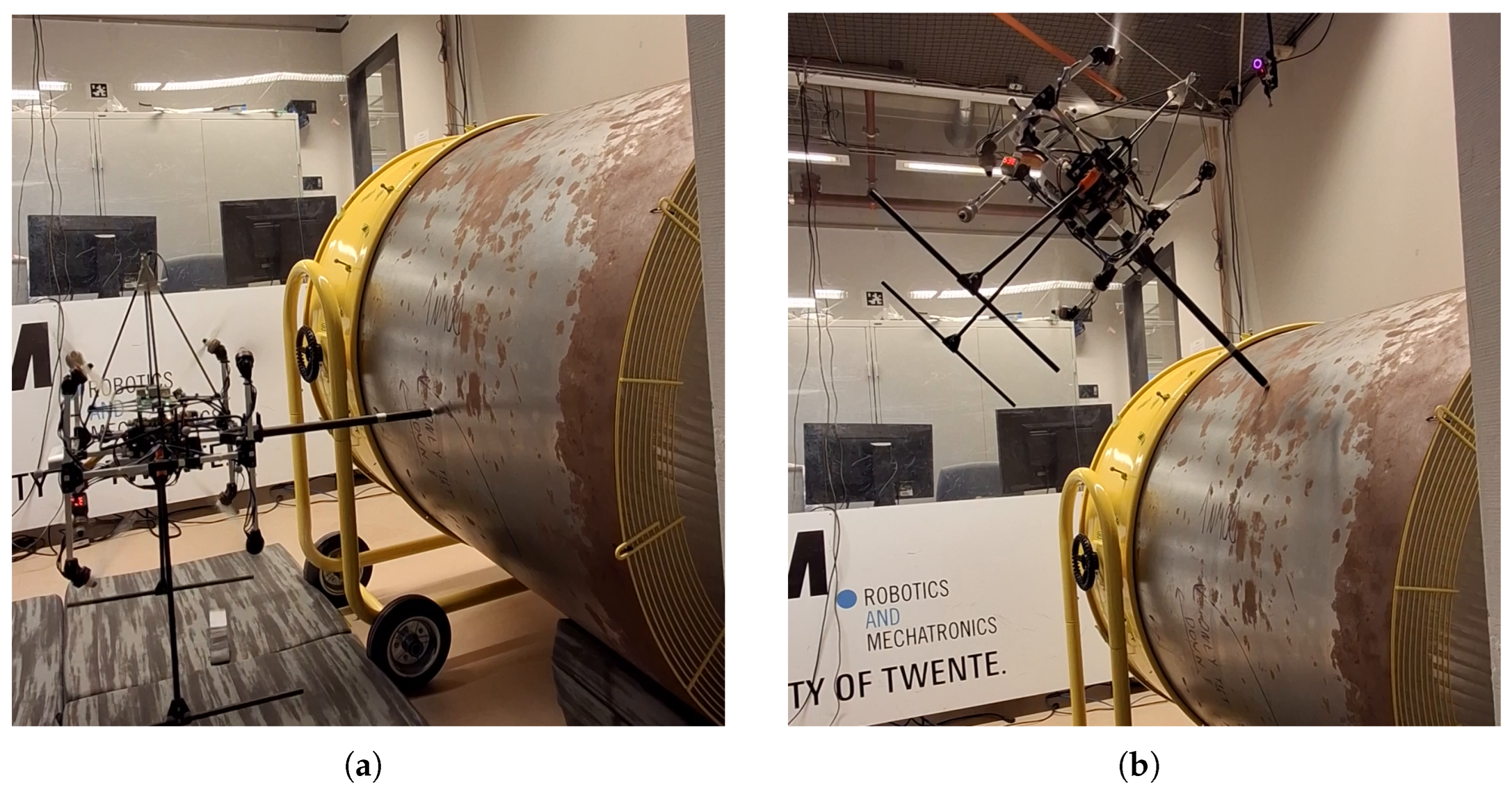
A circular pipe with a radius of 0.55 [m] is used to demonstrate the omnidirectional sliding capability. The EE slides from an initial position, shown in
Figure 7, to a maximum of
in roll, while keeping the EE normal to the surface, after which it returns to the initial position. The desired way-points are placed inside the pipe with a depth of 3 [cm] each and the admittance filter must adjust the desired trajectory to maintain contact with the pipe.
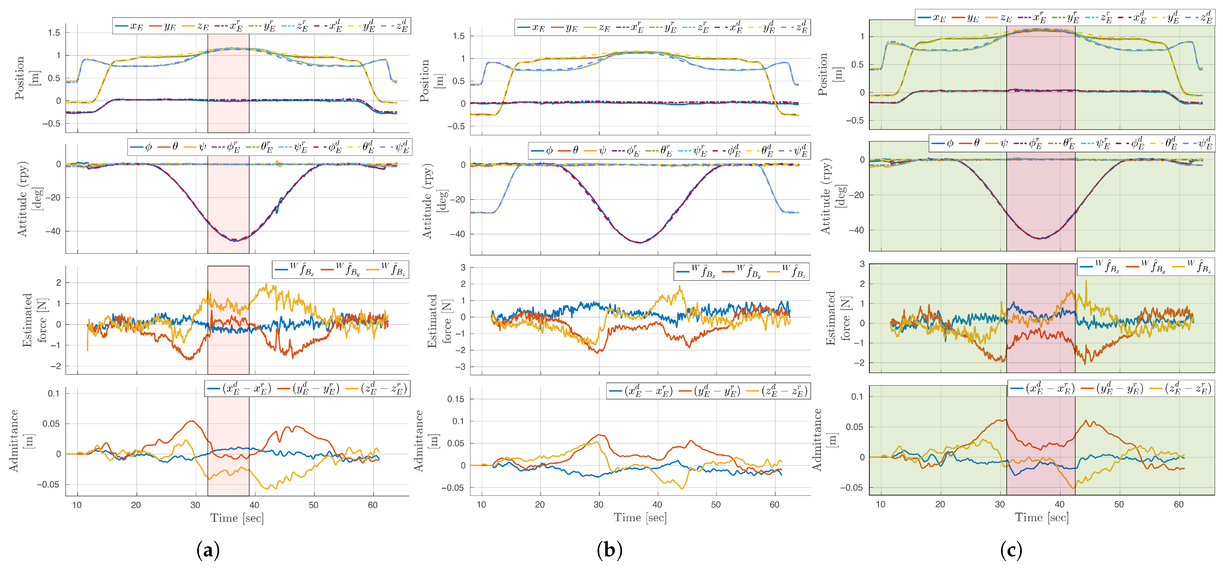
The axis of the pipe is initially parallel with the world-frame x-axis. Thus, the initial contact force is primarily along the world-frame y-axis. The forces estimated in should primarily be friction forces. To demonstrate the effects of modeling errors on maintaining continuous contact and the success of the wrench map identification approach to overcome the issues, the sliding task is performed using, first, a single linear wrench map using the nominal allocation matrix; second, a single globally optimized allocation matrix identified from data spanning two attitude regions (R1 and R3); and finally, with a piecewise linear wrench map using multiple optimized allocation matrices.
The RMS and max tracking errors of the sliding experiments, found in
Table 1, show that the piecewise linear approach achieves the best overall tracking. The piecewise linear approach has a lower RMS tracking error in x- and y-directions compared to the nominal one at the cost of a slightly increased RMS tracking error in the z-direction. We attribute this to the optimized allocation matrix effectively redistributing errors across axes to improve overall tracking consistency. We assume that gathering more and richer data will improve the tracking further. The single optimized allocation matrix performs well in y- and z-directions but worse in the x-direction due to the dataset spanning two regions (R1 and R3) which primarily contain data in these directions, indicating that the optimization effectively improves the input allocation but is sensitive to the directional coverage.
5.2.1. Nominal Allocation Matrix
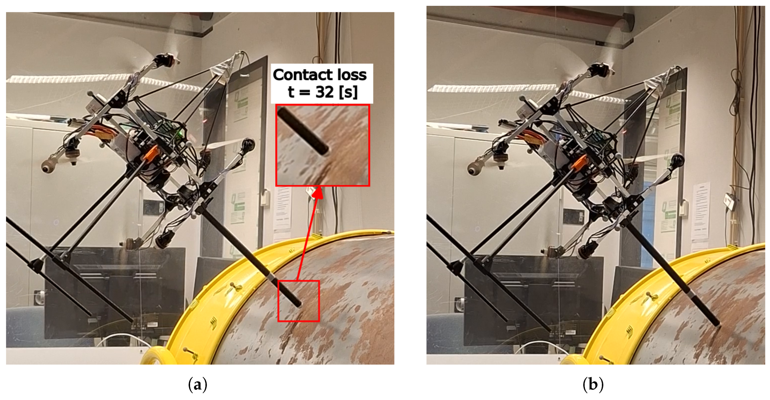
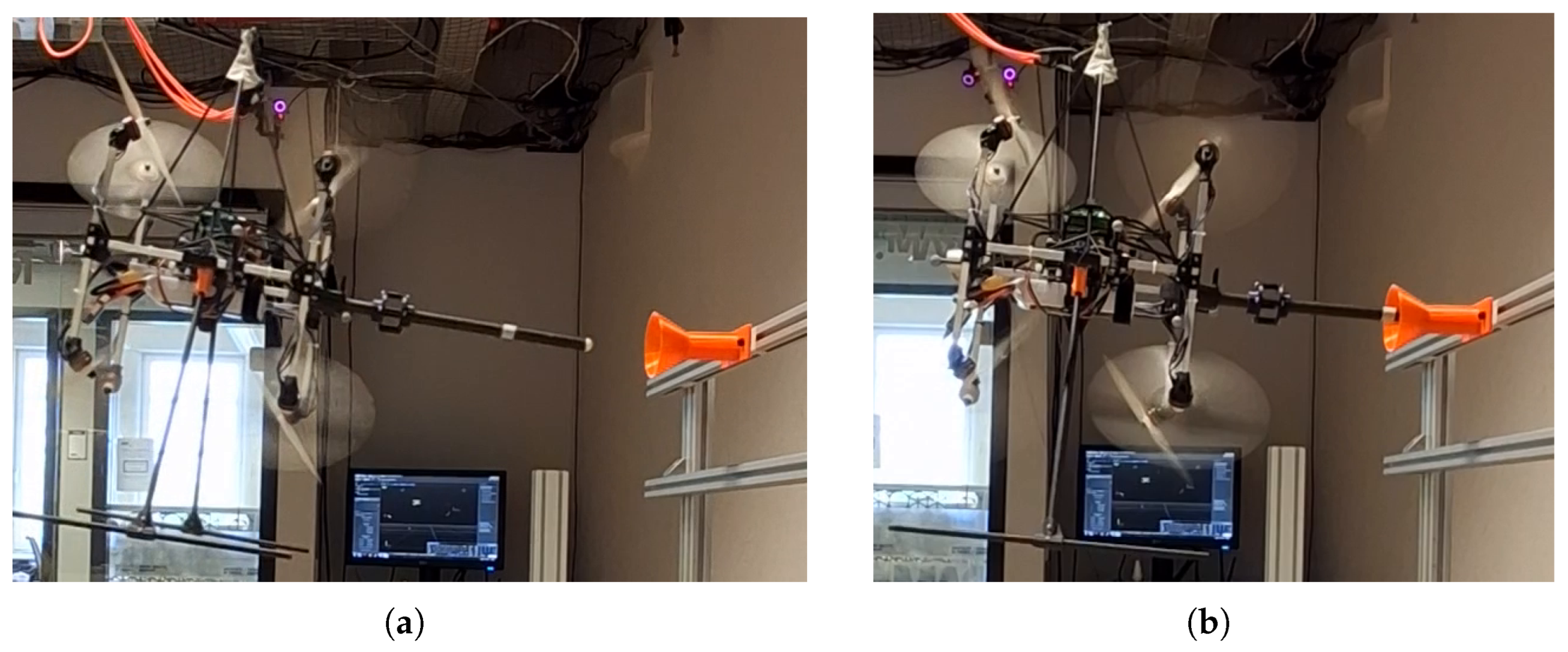
A snapshot of the apex of the flight is shown in
Figure 8a. It can be seen that contact is unexpectedly lost at
[s]. This occurs due to a modeling error causing a sudden force estimation of about 1 [N] in the positive z-axis. The admittance filter then yields a compliant reference at a higher position than intended due to this erroneous force estimation in
. In
Figure 9a, the MRAV states of the sliding experiment with the nominal allocation matrix are shown.
5.2.2. Single Optimized Allocation Matrix
In
Figure 9b, the MRAV states of the sliding experiment with the single optimized allocation matrix are shown. In contrast to the nominal allocation matrix, contact is successfully maintained with the pipe, as captured in
Figure 8b. Further, a contact force continues to be observed in negative
. The single optimized allocation matrix yields improved RMS tracking performance overall compared to the nominal allocation matrix, except in the x-direction.
5.2.3. Multiple Optimized Allocation Matrices
In
Figure 9c, the MRAV states of the sliding experiment with the piecewise linear wrench map are shown. Compared to the single allocation matrix, the force estimation looks more symmetric. Contact is again effectively maintained throughout the sliding. The system switches between wrench maps around
[s]. The piecewise linear wrench map achieves a lower RMS tracking error in the x-direction compared to the other approaches, while exhibiting comparable RMS tracking errors in all other metrics.
5.3. Peg-in-Hole Task
The objective of the peg-in-hole experiment is to insert the EE into a 10 cm funnel, maintain its position inside, and then extract it. There is a coupling between the EE and body of the Omnirotor to reduce vibrations. A hole has been designed with a funnel of an entrance diameter of 8 [cm] narrowed to a diameter of 19 [mm] at the funnel end. With the end-effector of diameter 16 [mm], there is a play of 1.5 [mm]. The hole is placed with its axis aligned with the world-frame
y-axis. To demonstrate the attitude compliance of the system, the Omnirotor approaches the hole with an end-effector orientation of
in roll. Snapshots of the approach and insertion of the peg are shown in
Figure 10. The peg-in-hole is performed with the nominal allocation matrix.
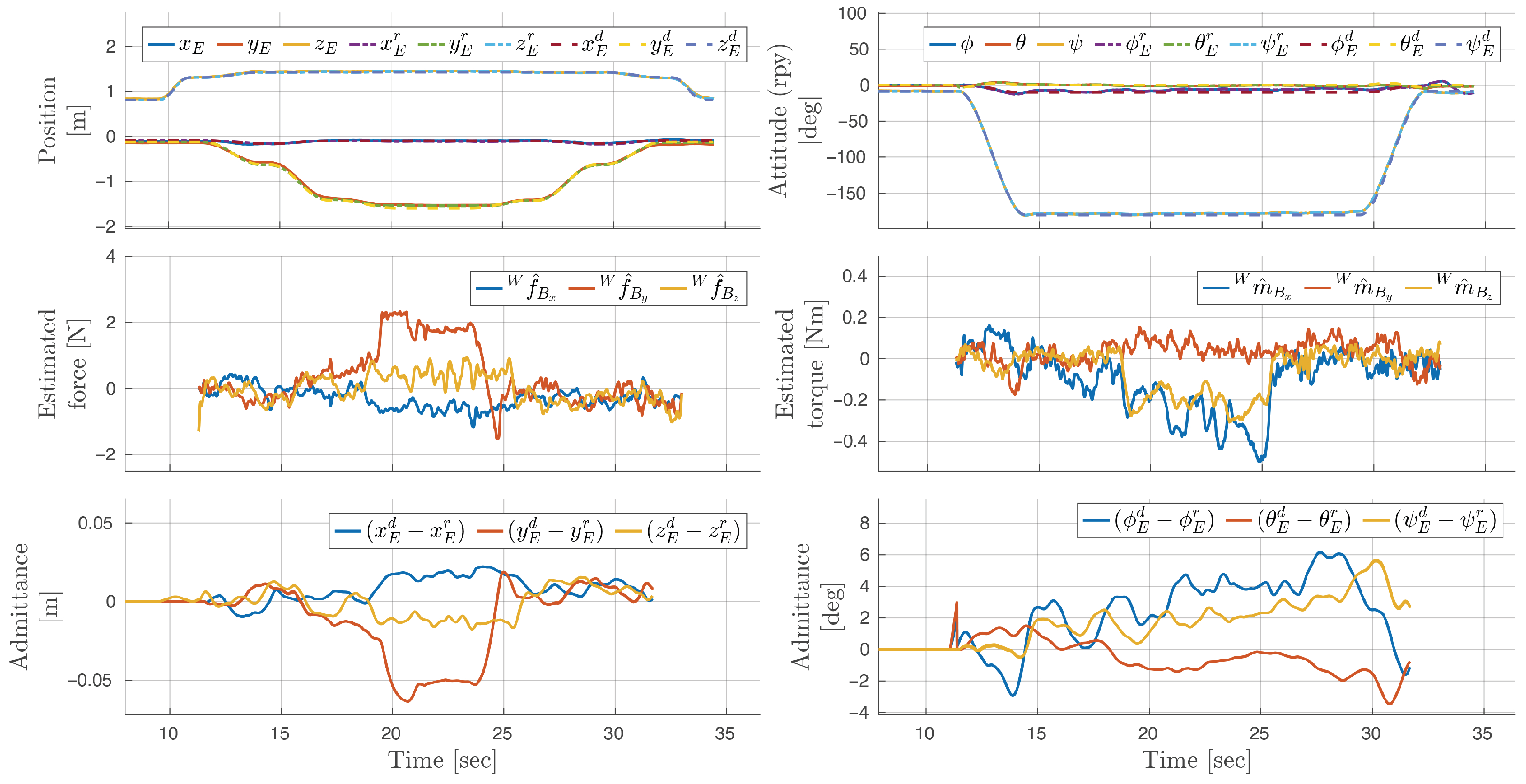
The plots of the MRAV position, velocity states, and wrench observer during the successful peg-in-hole are displayed in
Figure 11. The plots of the attitude and admittance filter show that the roll angle is adjusted from
to about
in response to the estimated moment on the EE, allowing for complete insertion of the peg.
6. Conclusions
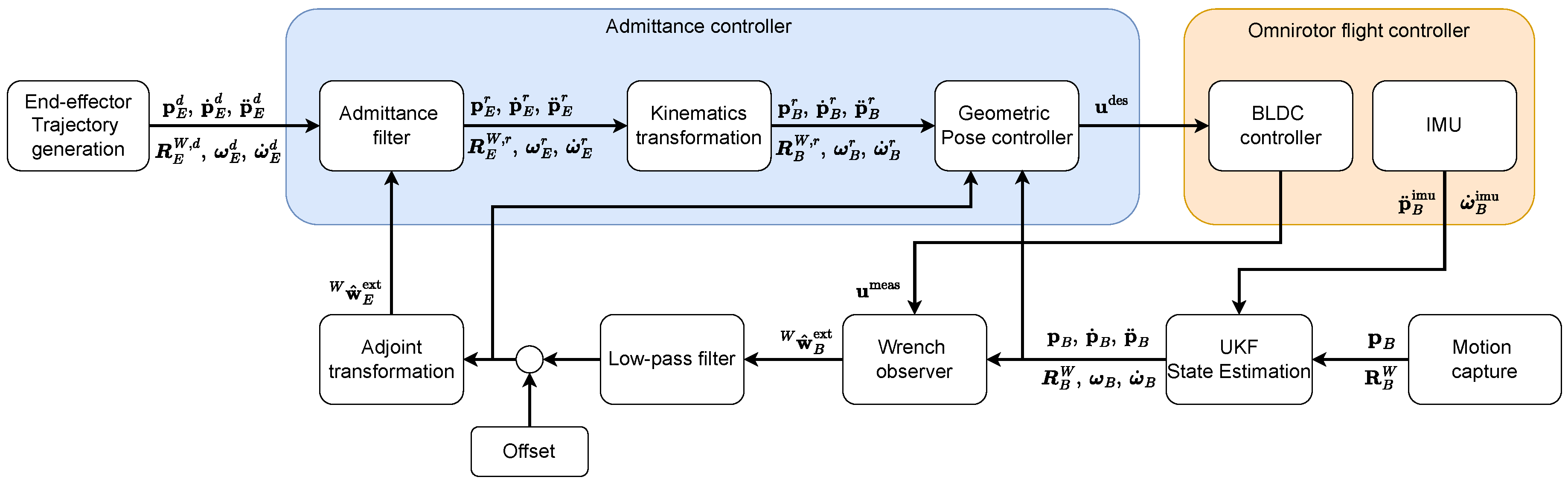
In this paper, we validate admittance-filter-based physical interaction control for an omnidirectional aerial platform, the Omnirotor, using an acceleration- and momentum-based wrench observer for external wrench estimation. The framework is experimentally evaluated through point-contact, sliding, and peg-in-hole tasks, demonstrating that stable and bounded interaction is achieved through both position and attitude compliance. To address modeling errors arising from mutual aerodynamic interference, we introduce a novel input allocation method that identifies the platform’s wrench map from data collected during hovering. This method improves performance in continuous physical interaction involving large-angle maneuvers, such as sliding along the circumference of a pipe, by mitigating sudden and inaccurate force estimates, which can cause unpredictable behavior such as loss of contact, when interaction forces represent only a small fraction of the platform’s weight.
Future work will focus on a more extensive quantitative validation of the proposed wrench map identification approach. For example, a force–torque sensor mounted on the end-effector may be used as ground truth to further assess the accuracy of the wrench observer during physical interaction. The method will also be extended to compensate for modeling errors in torque generation. In addition, smoother switching strategies between allocation matrices will be investigated to avoid control input discontinuities. Further refinements include studying alternative partitions and analysis of the optimal number of measurements per region, as well as conducting more exhaustive experimental evaluations covering the full space. Finally, a systematic sensitivity and robustness analysis will be performed.