Proceeding Paper

Thermoelastic Stress Analysis and Dissipated Energy Evaluation Using Infrared-Optical Synchronous Measurement †

1
Department of Mechanical Engineering, Kobe University, Kobe 657-8501, Japan
2
Fuji Engineering Co., Ltd., Fukuoka 830-0073, Japan
*
Author to whom correspondence should be addressed.
Presented at the 15th International Workshop on Advanced Infrared Technology and Applications (AITA 2019), Florence, Italy, 17–19 September 2019.
Proceedings 2019, 27(1), 50; https://doi.org/10.3390/proceedings2019027050
Published: 5 December 2019

Abstract

:
On the infrared thermography image, a false temperature change caused by the relative displacement between moving object and infrared camera is obtained. This paper shows the motion compensation system with the infrared-optical synchronous measurement. Displacement information of the specimen is calculated from the series of visible light image using the digital image correlation method (DIC). The displacement information on the visible image is reflected to the infrared image by the homography transformation. The random white pattern which can’t be detected by the infrared camera was drawn on the measured surface for DIC process. The developed motion compensation system was applied to the thermoelastic stress analysis and dissipated energy measurement. It was confirmed that a false temperature change and edge effect can be removed by using developed motion compensation system.

1. Introduction

When cyclic loading is applied to the materials, temperature change caused by the thermoelastic effect was measured by infrared thermography. The measured temperature change makes it possible to analysis the magnitude and distribution of stress in non-contact condition [1]. In addition, the temperature change due to energy dissipation which caused by micro-plastic deformation can be measured [2]. The fatigue limit rapidly estimation based on the measurement of energy dissipation has been studied by a lot of researcher [3,4,5,6,7,8]. When the loading is applied to the materials, an interested point in the measuring object moves in the view of infrared thermography by the rigid body movement and deformation of an object. This relative moving is measured as a fake and apparent temperature change. This false temperature change is a noise component in thermoelastic stress analysis or dissipated energy evaluation. In order to improve accuracy of thermoelastic stress analysis and dissipated energy measurement, the motion compensation system with the optical-infrared synchronous measurement was developed. This paper described the motion compensation system and the effect of this system on the thermoelastic stress analysis and energy dissipated measurement.

2. Thermoelastic Effect and False Temperature Change

In the thermoelastic stress analysis, the change of the principal stress Δσ on the material can be determined from the temperature change ΔTE based on the thermoelastic effect as shown in the following equation:
Δ T E = k T Δ σ
T and k indicates the absolute temperature of the materials and thrmoelastic coefficient, respectively. The temperature rise due to irreversible energy dissipation ΔTD occurs at the maximum tensile stress and at the maximum compressive stress. Thus, the measured temperature change T(t) on the surface includes ΔTE and ΔTD. Therefore, temperature change due to dissipated energy ΔTD can be obtained as the component having double frequency of the load signal using basically Fourier analysis [3,8]. ΔTD is related to the fatigue damage, so that the fatigue limit of the materials can be estimated by the rapid estimation method based on the dissipated energy measurement. Since rigid body movement and deformation occur by the applied force, an interested point of measuring object moves in the field of view. The observation point on a certain pixel moves to next pixel in the next frame, so that the measured temperature change is a false temperature change of the observation point.

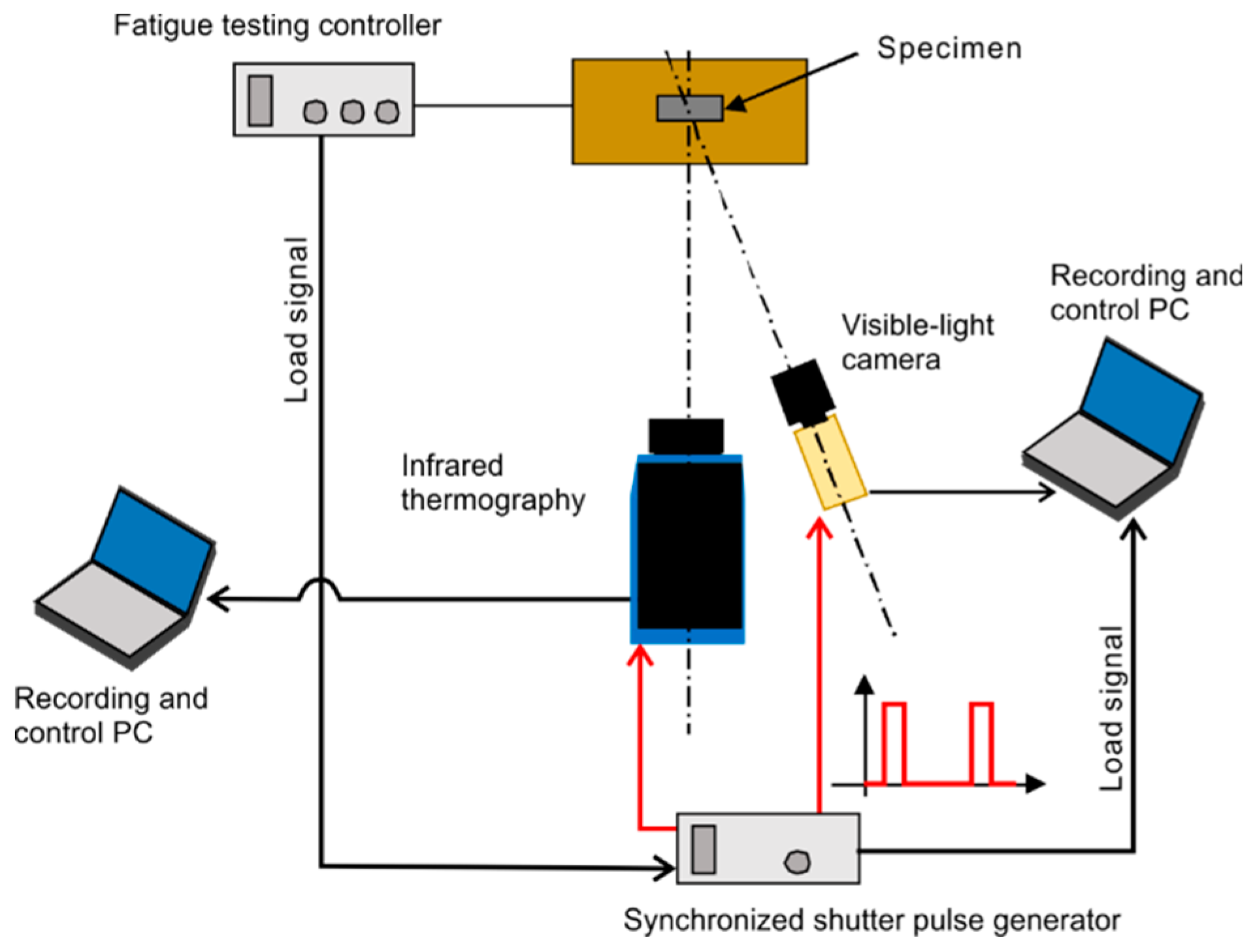
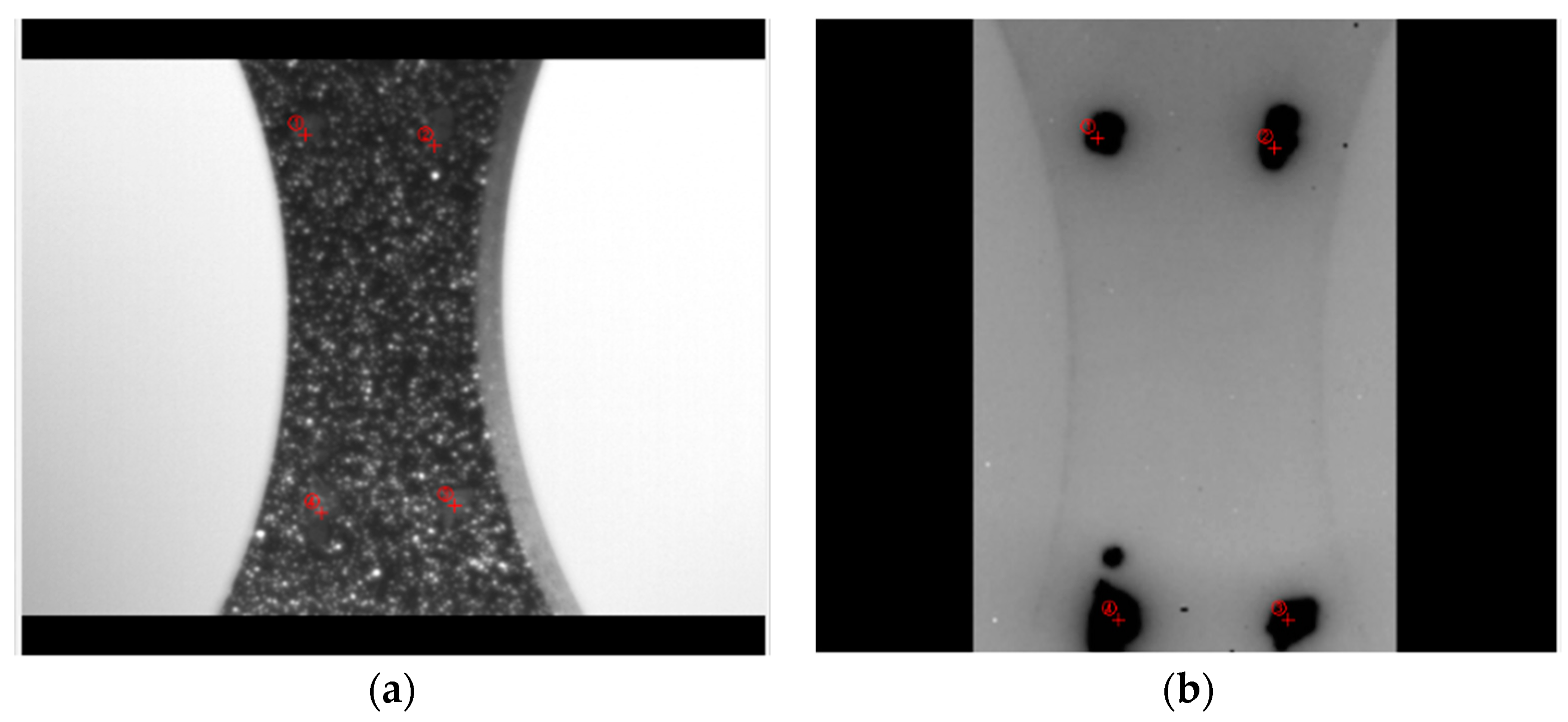
3. Motion Compensation System with the Infrared-Optical Synchronous Measurement

Various motion compensation methods have been proposed to remove a false temperature change. Sakagami et al. [9] have proposed a method of position correction by DIC (digital image correlation) using feature pattern in infrared images. Daoyun Chen et al. [10] and W. Wang [11] developed a motion compensation using images captured by visible light camera and infrared thermography. In this method, the visible image and infrared image are obtained at different timings, or these image are obtained at different surface of same object, respectively.
To correct the displacement and deformation of object, the movement vector of each pixel (optical flow vector) of the object should be detected using DIC. However, it is difficult to detect optical flow vector in infrared image with high accuracy, because the spatial resolution of infrared thermography is low and there is no fine future pattern in infrared image for DIC. Therefore, visible-light camera was used to obtain an optical flow vector for each pixel in infrared thermography. The speckled pattern on specimen was drawn with a paint not affecting infrared thermography, and it was taken with visible-light camera to acquire an optical flow vector.
In the proposed method, visible images and infrared images are obtained at same timings for same surface, synchronously. A schematic illustration of the recording system is shown in Figure 1. The infrared thermography and the visible-light video camera are driven by the shutter pulse supplied from the synchronized shutter pulse generator, so that synchronous imaging becomes possible. The load signal from the controller of fatigue testing machine is recorded at same timings. The loading signal waveform can be used as the time stamp of visible image and infrared image.
There is a parallax difference between visible-light camera and infrared thermography camera, so that the optical flow vector obtained by optical image cannot be directly reflected to the thermography image. A homography transformation convert the optical flow vector in the visible-light image to the infrared image. The advantage of homography transformation is that it is possible to obtain homography transformation matrix H from the captured image without knowing the position, posture, focal length, etc. of each camera. The homography transformation matrix H is calculated by acquiring four pairs of coordinates on the two images where the same point of the object, as shown in Figure 2.

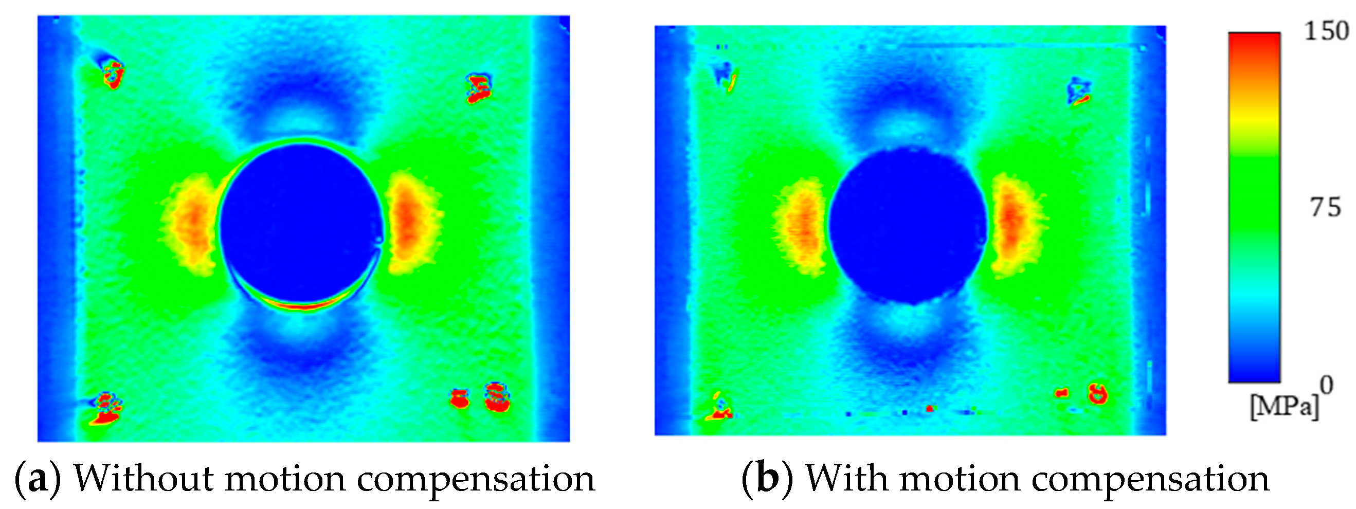
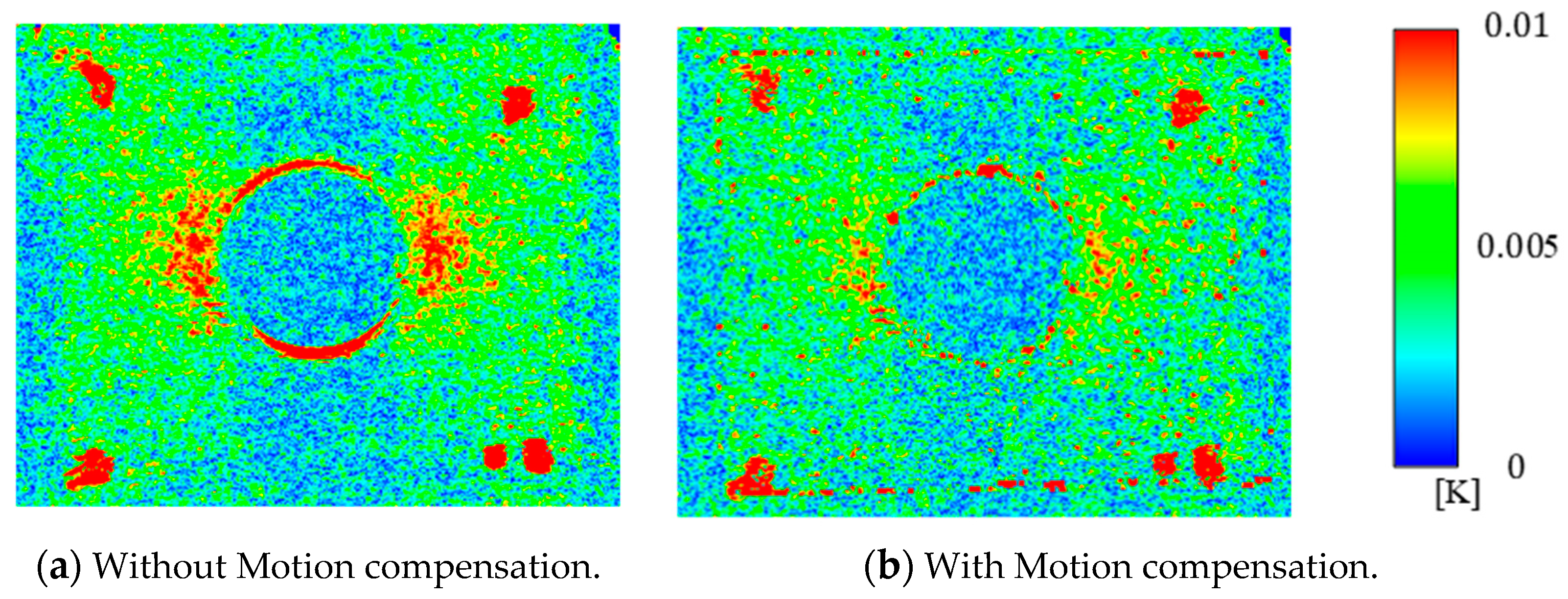
4. Experiment Results

An aluminum alloy (A5052) with circular hole with a diameter of 11 mm was used in the experiment. The loading condition was a sinusoidal stress waveform with stress ratio R = −1 and loading frequency f = 5 Hz, and the nominal stress amplitude was set to σa = 50 MPa. As the measurement conditions, the frame rate of the visible-light camera and infrared thermography were set to 100 Hz and the photographing time was set to 10 s.
The sum of principal stress distribution and the dissipated energy distribution are shown in Figure 3 and Figure 4, respectively. Displacement of about 120 μm occurred in the lower part of the circular hole by DIC in visible-light image. From the sum of principal stress distribution in the case where the position correction is not applied, it was found that high stress appears in the edge portion of the lower portion of the circular hole. On the other hand, in the case where the position correction is applied, high stress due to the edge effect does not appear. Similarly in the dissipated energy distribution, high dissipated energy which seems to be an edge effect does not appear due to position correction. In the distribution of the dissipated energy, the dissipated energy in the vicinity of the circular hole is reduced by applying the position correction. It was considered that noise components of dissipated energy due to apparent temperature change can be removed.

5. Conclusions

The motion compensation system with optical-infrared infrared synchronous measurement was developed. In this study, the visible-light image and infrared image are taken for same face in sync, and the optical flow vector obtained in visible-light image was reflected to the infrared image. There is a parallax difference between visible-light camera and infrared thermography camera, so that a homography transformation convert the optical flow vector in the visible-light image to the infrared image. As a result of measuring with developed system, it was found that it is possible to remove the edge effect and the false temperature change.

References

  1. Sakagami, T. Remote nondestructive evaluation technique using infrared thermography for fatigue cracks in steel bridges. Fatigue Fract. Eng. Mater. Struct. 2015, 38, 755–779. [Google Scholar] [CrossRef]
  2. Sakagami, T.; Kubo, S.; Tamura, E.; Nishimura, T. Identification of plastic-zone based on double frequency lock-in thermographic temperature measurement. In Proceedings of the ICF11, Turin, Italy, 1 October 2005. [Google Scholar]
  3. Brémond, P.; Potet, P. Lock-in thermography: A tool to analyze and locate thermomechanical mechanisms in materials and structures. Aerosp./Def. Sens. Simul. Controls 2001, 4360, 560–567. [Google Scholar]
  4. Luong, M. Infrared thermographic scanning of fatigue in metals. Nucl. Eng. Des. 1995, 158, 363–376. [Google Scholar] [CrossRef]
  5. La Rosa, G. Thermographic methodology for rapid determination of the fatigue limit of materials and mechanical components. Int. J. Fatigue 2000, 22, 65–73. [Google Scholar] [CrossRef]
  6. Krapez, J.-C.; Pacou, D. Thermography detection of damage initiation during fatigue tests. Proc. SPIE 2002, 4710, 435–449. [Google Scholar]
  7. Hayabusa, K.; Inaba, K.; Ikeda, H.; Kishimoto, K. Estimation of fatigue limits from temperature data measured by IR thermography. Exp. Mech. 2017, 57, 185–194. [Google Scholar] [CrossRef]
  8. Shiozawa, D.; Inagawa, T.; Washio, T.; Sakagami, T. Accuracy improvement in dissipated energy measurement by using phase information. Meas. Sci. Technol. 2017, 28, 44004. [Google Scholar] [CrossRef]
  9. Sakagami, T.; Yamaguchi, N.; Kubo, S.; Nishimura, T. A new full-field motion compensation technique for infrared stress measurement using digital image correlation. J. Strain Anal. Eng. Des. 2008, 43, 539–549. [Google Scholar] [CrossRef]
  10. Chen, D.; Sun, S.; Dulieu-Barton, J.; Li, Q.; Wang, W. Crack growth analysis in welded and non-welded T-joints based on lock-in digital image correlation and thermoelastic stress analysis. Int. J. Fatigue 2018, 110, 172–185. [Google Scholar] [CrossRef]
  11. Wang, W.; Fruehmann, R.K.; Dulieu-Barton, J.M. Application of Digital Image Correlation to Address Complex Motions in Thermoelastic Stress Analysis. Strain 2015, 51, 405–418. [Google Scholar] [CrossRef]
Figure 1. Schematic illustration of optical-infrared thermography synchronous measurement system.
Proceedings 27 00050 g001
Figure 2. Four pairs of coordinates for obtaining a homography transformation matrix: (a) Visible image, (b) Infrared thermography.
Proceedings 27 00050 g002
Figure 3. Distributions of measured stress amplitude (σa = 50 MPa).
Proceedings 27 00050 g003
Figure 4. Distributions of dissipated energy (σa = 50 MPa).
Proceedings 27 00050 g004

