Proceeding Paper

Analysis of Piezoelectric Diaphragms in Impedance-Based Damage Detection in Large Structures †

Department of Electrical Engineering, School of Engineering, Bauru, São Paulo State University (UNESP), 17033-360 Bauru-SP, Brazil
*
Author to whom correspondence should be addressed.
Presented at the 4th International Electronic Conference on Sensors and Applications, 15–30 November 2017; Available online: https://sciforum.net/conference/ecsa-4.
Proceedings 2018, 2(3), 131; https://doi.org/10.3390/ecsa-4-04896
Published: 14 November 2017

Abstract

:
The use of low-cost transducers such as piezoelectric diaphragms in structural health monitoring (SHM) applications based on the electromechanical impedance (EMI) method has grown in recent years. Although many studies report the feasibility of such transducers for impedance-based damage detection, the experiments are typically performed on small structures. Therefore, the objective of this work is to perform an experimental analysis of the feasibility of the piezoelectric diaphragms for the detection of damage in large structures. Several tests were carried out on a large aluminum plate in which a diaphragm was attached. The electrical impedance signatures of the transducer were collected and a basic damage index was calculated in order to verify the feasibility of quantifying the size of the damage at different distances from the transducer. The experimental results indicate that the piezoelectric diaphragms have a good sensitivity to provide a damage size classification in large structures. In addition, the sensitivity to damage detection and classification decrease as the distance between the transducer and the damage increases. Therefore, the results reported in this study indicate that low-cost piezoelectric diaphragms are feasible for impedance-based SHM applications in large structures.

1. Introduction

The use of low-cost piezoelectric transducers in the field of structural health monitoring (SHM) has grown in recent years with the objective of ensuring, increasingly, a high degree of performance and structural safety [1,2]. In this context, the need for the development of non-destructive testing (NDT) techniques applied to the monitoring of structures arises, in order to promote robust, minimally invasive systems and simple application in the diagnosis of failures [2]. Among the NDT techniques [3], such as Lamb waves [4,5], acoustic emission [6,7], comparative vacuum [8], eddy current [9], the electromechanical impedance (EMI) technique is characterized by the simplicity in implementation and by using piezoelectric transducers for damage detection in structures [10,11].
Basically, a piezoelectric transducer is attached to the monitored structure and this coupling causes the piezoelectric effect to produce an interaction between the mechanical impedance of the structure and the electrical impedance of the transducer. Therefore, in this context, the structural condition can be monitored by measuring and analyzing the electrical impedance signatures of the transducer [10,11]. Although there are many studies based on the EMI technique that report the feasibility of low-cost piezoelectric diaphragms for damage detection, the most experiments use small structures. Based on this information, the objective of this article is to verify the feasibility of piezoelectric diaphragms for damage detection based on the EMI technique in large structures.
The study takes into account the sensitivity of the measurements to the size and distance of damage embedded in a large aluminum structure, a material commonly used in various engineering structures. This paper is organized as follows: the EMI technique and the piezoelectric transducer are presented in Section 2; the experimental procedures are described in Section 3; the results are presented and discussed in Section 4. The paper ends with the conclusions in Section 5, followed by the bibliographical references.

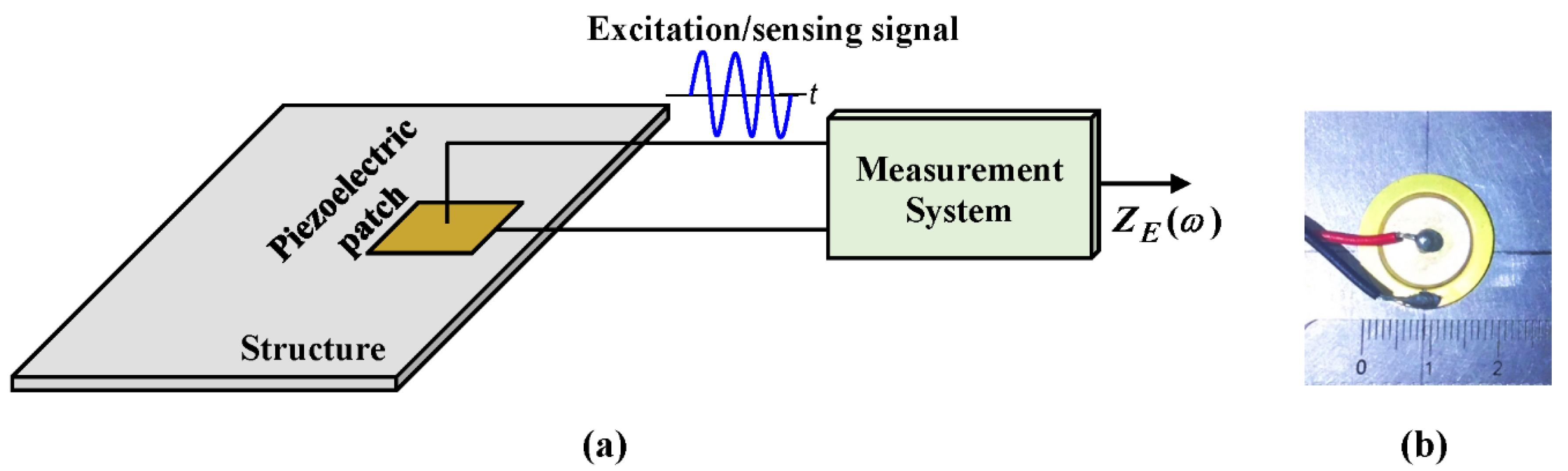
2. The Electromechanical Impedance (EMI) Technique and Piezoelectric Transducer

The EMI technique is based on the piezoelectric effect, which establishes an electromechanical coupling between the structure and the transducer, according to Figure 1a. Typically, the transducers used in impedance-based SHM applications are PZT (Lead zirconate titanate) ceramics. However, the transducer used in this study is a low-cost piezoelectric diaphragm, 7BB-20-6, from Murata Manufacturing, as shown in Figure 1b.
In the EMI method, a piezoelectric transducer works either as an actuator (reverse piezoelectric effect) or as a sensor (direct effect), establishing the relationship between the mechanical impedance of the structure ( Z S ( ω ) ) and the electrical impedance of the transducer ( Z E ( ω ) ), as Equation (1) [12].
Z E ( ω ) = 1 j ω τ ( ε 33   T Z S ( ω ) Z S ( ω ) + Z P ( ω ) d 3 x 2 Y ^ x x E ) 1
where Z P ( ω ) is the mechanical impedance of the transducer, ω is the angular frequency, τ is a geometric constant related to the shape and dimensions of the transducer, ε 33   T is the dielectric constant for a constant mechanical stress T , Y ^ x x E is the Young’s modulus for a constant electric field E , d 3 x is the piezoelectric constant and j is the imaginary unit.
According to Equation (1), by the excitation of the transducer in a certain frequency range and the corresponding measurement of its electrical impedance, it is possible to detect variations in the mechanical impedance of the monitored structure caused by damages, since a change in the mechanical impedance causes a variation in the electrical impedance signature. Typically, the identification, classification and quantification of damage are performed through statistical indices comparing two electrical impedance signatures: the first, which refers to the healthy structure (baseline) and the second, which refers to a possible damage condition. One of the most used indices in the literature is the root mean square deviation (RMSD), which is based on the Euclidean norm as observed in Equation (2) [13].
R M S D = n N ( Z n , d Z n , h ) 2 Z n , h 2
where Z n , h and Z n , d are, respectively, the electrical impedance signatures of the transducer with the undamaged structure (also known as baseline), and after the occurrence of damage, both measures in the frequency n, where N is the total number of frequencies analyzed.
The feasibility of piezoelectric diaphragms such as the 7BB-20-6 diaphragm shown in Figure 1b for the detection of structural damage has typically been analyzed for small structures [12]. However, the relationship between the size of the structure and the transducer may interfere with the sensitivity to damage [14]. Thus, it is important to analyze the sensitivity of the piezoelectric diaphragm for the diagnosis of failures in large structures. The experimental setup used to perform this analysis is presented in the next section.

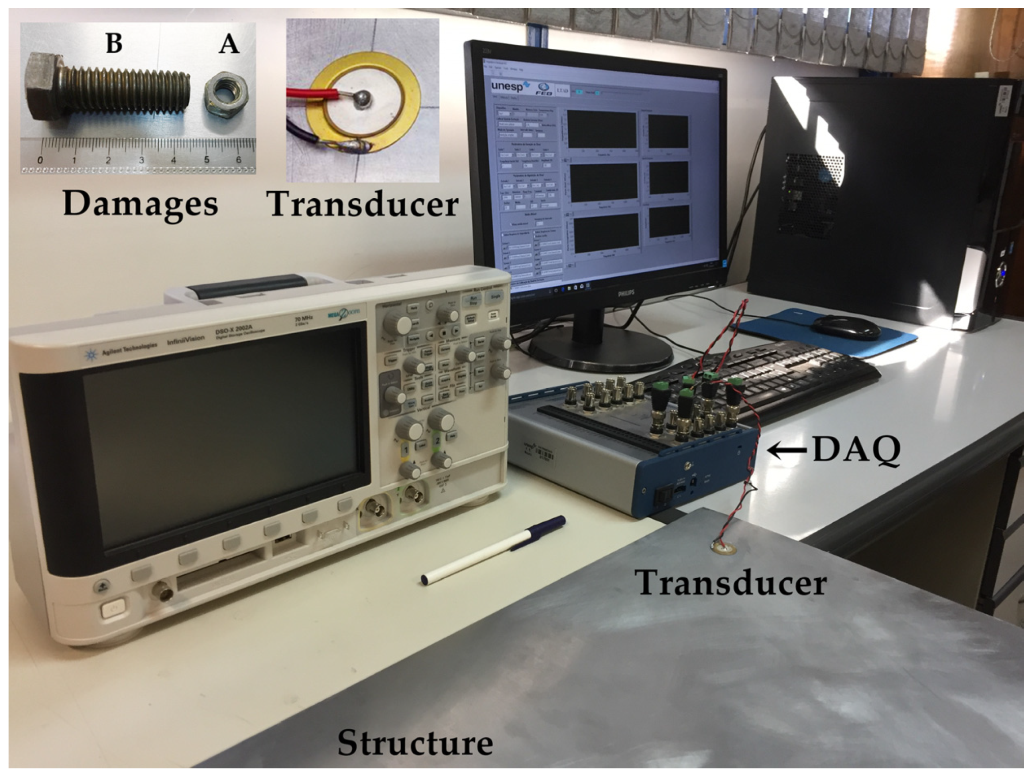
3. Experimental Setup

To investigate the sensitivity of the low-cost transducer to damage detection in large structures, an aluminum plate with dimensions of 2000 mm × 1000 mm × 2 mm, with a mass of 10.6 kg was used, supported on blocks of foam. The transducer used, a 7BB-20-6 diaphragm from Murata Manufacturing, has an active piezoelectric element with a diameter of 14 mm and was installed in the diagonal of the structure using cyanoacrylate glue. The structural damage was simulated by the addition of two metallic masses of 0.005 kg (Damage A) and 0.04 kg (Damage B), that corresponds a percentage of 0.005% and 0.37%, respectively. The two masses were coupled at 0.5 m from the sensor in order to study the behavior of the RMSD index with increased structural damage. Subsequently, the same damages were inserted at 1.5 m from the sensor in order to analyze the sensitivity of the sensor at a distance from the damage. The experimental setup is shown in Figure 2.
The impedance measurement system used was proposed by [15]. An NI-USB-6366 multifunctional data acquisition (DAQ) device from National Instruments® and a personal computer with LabVIEW software were used. The system was configured to excite the transducer with a chirp signal of 1 V amplitude and the response signals were sampled at a rate of 2 MS/s (samples/second). The impedance signatures were obtained in a frequency range from 0 to 500 kHz with step of 2 Hz. With these signatures, the RMSD index was calculated in sub-bands of 10 kHz and, in this way, the sensitivity of the transducer was verified for the detection of damages in the studied structure. The results are presented and discussed in the next section.

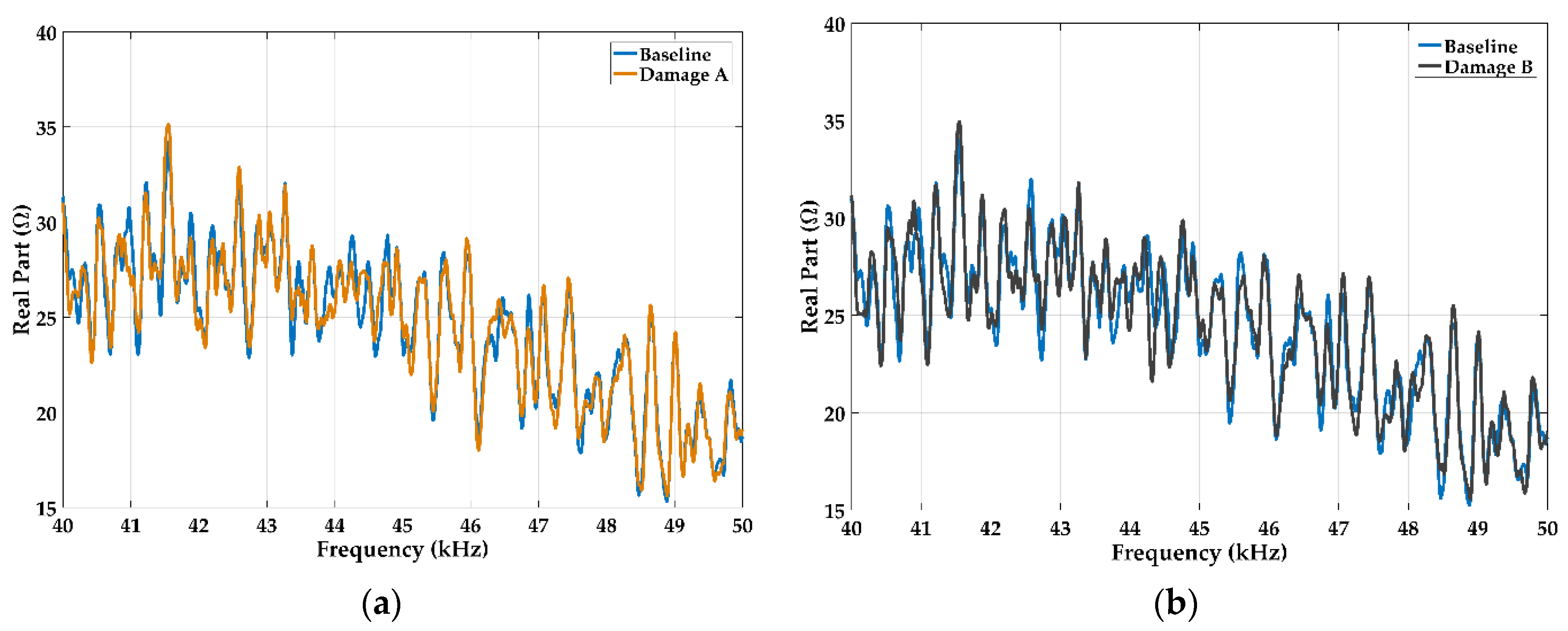
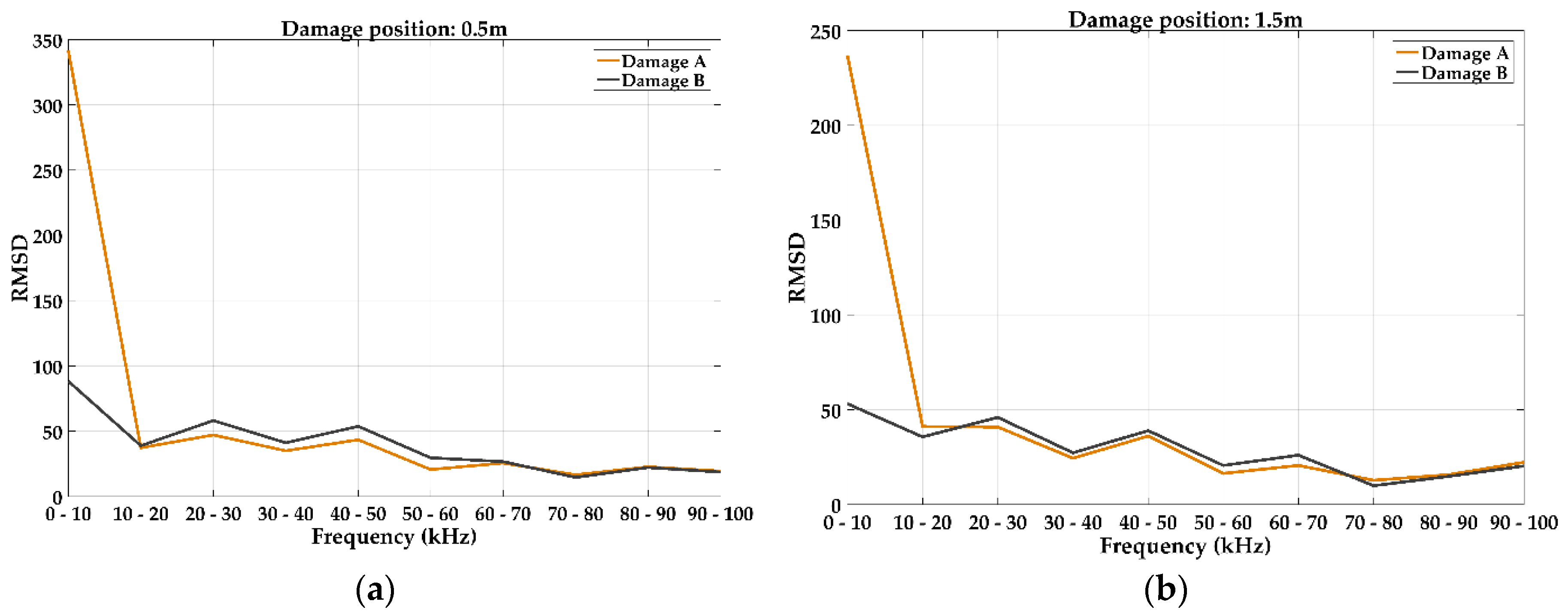
4. Results and Discussion

As described, structural damage changes the electrical impedance signature in relation to the baseline. Thus, Figure 3 shows the real part of the impedance curves in the frequency range from 40 kHz to 50 kHz obtained for damages “A” and “B” describe in the previous section.
For the damage characterization by the RMSD index, the selection of the frequency range occurred in the band which the index presented the most expressive values. For this study, this range was from 0 to 100 kHz.
Figure 4 shows the behavior of the RMSD index for the two damage positions.
According to Figure 4, for both positions, the RMSD presented a similar behavior, that is, for the sub-bands of up to 20 kHz the minor damage (A) presented higher indices than the indices generated by the impedance signatures of the major damage (B). From 20 kHz to 100 kHz the RMSD index increases with damage size, allowing the classification of the damage. Therefore, for this range, it can be affirmed that this method can be applied in order to monitor the evolution of the size of the damage in large structures. For bands above 100 kHz the method is effective to detect, but was not effective to make a damage size classification.
After this analysis, the sensitivity of the method at a distance from the damage to the sensor was verified. The RMSD index for damage at 0.5 m and 1.5 m from the transducer are shown in Figure 5. Based on these results, it is observed that the RMSD decreased with the distance for both damages for the frequency of up to 100 kHz. Thus, this index shows to be effective in quantifying the distance of the damage from the transducer, a significant factor for damage localization systems. For frequencies above 100 kHz it was not possible to establish the decay relationship of the index with the distance of damage from the transducer.

5. Conclusions

The use of piezoelectric transducers for monitoring large structures is of great importance for ensuring a high degree of structural safety in fields related to civil, naval, mechanical and aerospace engineering. Therefore, this work presented a feasibility of a low-cost piezoelectric transducer in the diagnosis of failures in large structures based on the electromechanical impedance technique. Two types of damages were coupled whose masses representing 0.005% and 0.37% of the total structure mass and, thus, the electrical impedance signatures of the transducer were collected. To characterize the damage, the RMSD index was calculated and, based on the obtained results, it was verified that its values are proportional both to the damage size and distance from the transducer. Thus, the RMSD index proved to be effective in characterizing both the size and distance of the damage from the transducer, being a primordial factor for systems for monitoring and locating failures. Therefore, under the experimental conditions analyzed in this study, it is concluded that piezoelectric diaphragms can be a low-cost alternative for the correct damage detection and size classification for large structures.

Author Contributions

Danilo Budoya, Leandro Campeiro and Ricardo Silveira conceived, designed and performed the experiments; Bruno Castro and Everaldo Freitas analyzed the data and discussed the results; Fabricio Baptista provided the support with the piezoelectric diaphragms and wrote the paper.

Acknowledgments

This work was supported in part by the São Paulo Research Foundation (FAPESP) (grants #2015/02500-6, #2015/24903-5, #2015/23272-1) and Capes Foundation, Ministry of Education of Brazil.

Conflicts of Interest

The authors declare no conflict of interest.

Abbreviations

EMIelectromechanical impedance
NDTnon-destructive testing
PZTLead zirconate titanate
RMSDroot mean square deviation
SHMstructural health monitoring

References

  1. Li, H.; Ren, L.; Jia, Z.; Yi, T.; Li, D. State-of-the-art in structural health monitoring of large and complex civil infrastructures. J. Civ. Struct. Health Monit. 2016, 6, 3–16. [Google Scholar] [CrossRef]
  2. Ostachowicz, W.; Güemes, J.A. New Trends in Structural Health Monitoring, International Centre for Mechanical Sciences, Courses and Lectures; Springer: Vienna, Italy, 2013; p. 434. [Google Scholar]
  3. Giurgiutiu, V. Embedded NDT with Piezoelectric Wafer Active Sensors. In Nondestructive Testing of Materials and Structures; Buyukozturk, O., Tasdemir, M.A., Gunes, O., Akkaya, Y., Eds.; Springer: Dordrecht, The Netherlands, 2013; Volume 6, pp. 987–992. [Google Scholar]
  4. Yu, L.; Leckey, C.A.C. Lamb wave-based quantitative crack detection using a focusing array algorithm. J. Intell. Mater. Syst. Struct. 2013, 24, 1138–1152. [Google Scholar] [CrossRef]
  5. Schmitt, M.; Olfert, S.; Rautenberg, J.; Lindner, G.; Henning, B.; Reindl, L.M. Multi reflection of lamb wave emission in an acoustic waveguide sensor. Sensors 2013, 13, 2777–2785. [Google Scholar] [CrossRef] [PubMed]
  6. Svečko, R.; Kusić, D.; Kek, T.; Sarjaš, A.; Hančič, A.; Grum, J. Acoustic emission detection of macro-cracks on engraving tool steel inserts during the injection molding cycle using PZT sensors. Sensors 2013, 13, 6365–6379. [Google Scholar] [CrossRef] [PubMed]
  7. Shahidan, S.; Pulin, R.; Bunnori, N.M.; Holford, K.M. Damage classification in reinforced concrete beam by acoustic emission signal analysis. Constr. Build. Mater. 2013, 45, 78–86. [Google Scholar] [CrossRef]
  8. Rulli, R.P.; Dotta, F.; da Silva, P.A. Flight tests performed by EMBRAER with SHM systems. Key Eng. Mater. 2013, 558, 305–313. [Google Scholar] [CrossRef]
  9. García-Martín, J.; Gómez-Gil, J.; Vázquez-Sánchez, E. Non-destructive techniques based on eddy current testing. Sensors 2011, 11, 2525–2565. [Google Scholar] [CrossRef] [PubMed]
  10. Annamdas, V.G.M.; Radhika, M.A. Electromechanical impedance of piezoelectric transducers for monitoring metallic and non-metallic structures: A review of wired, wireless and energy-harvesting methods. J. Intell. Mater. Syst. Struct. 2013, 24, 1021–1042. [Google Scholar] [CrossRef]
  11. Baptista, F.G.; Budoya, D.E.; Almeida, V.A.D.; Ulson, J.A.C. An Experimental Study on the Effect of Temperature on Piezoelectric Sensors for Impedance-Based Structural Health Monitoring. Sensors 2014, 14, 1208–1227. [Google Scholar] [CrossRef] [PubMed]
  12. Freitas, E.S.; Baptista, F.G.; Budoya, D.E.; Castro, B.A. Equivalent circuit of piezoelectric diaphragms for impedance-based structural health monitoring applications. IEEE Sens. J. 2017, 17, 5537–5546. [Google Scholar] [CrossRef]
  13. Campeiro, L.M.; Silveira, R.Z.M.; Baptista, F.G. Impedance-based damage detection under noise and vibration effects. Struct. Health Monit. 2017, 17, 1–14. [Google Scholar] [CrossRef]
  14. Baptista, F.G.; Vieira Filho, J.; Inman, D.J. Sizing PZT Transducers in Impedance-Based Structural Health Monitoring. IEEE Sens. J. 2011, 11, 1405–1414. [Google Scholar] [CrossRef]
  15. Baptista, F.G.; Vieira Filho, J. A new impedance measurement system for PZT-based structural health monitoring. IEEE Trans. Inst. Meas. 2009, 58, 3602–3608. [Google Scholar] [CrossRef]
Figure 1. (a) Principle of the EMI method [11] and (b) piezoelectric transducer used in this study.
Proceedings 02 00131 g001
Figure 2. Experimental Setup.
Proceedings 02 00131 g002
Figure 3. Impedance signatures for damage (a) A and (b) B at 0.5 m from the transducer.
Proceedings 02 00131 g003
Figure 4. RMSD index for the 0.5 m (a) and 1.5 m (b) positions relative to the transducer.
Proceedings 02 00131 g004
Figure 5. RMSD for damages A (a) and B (b) in two different positions.
Proceedings 02 00131 g005
Publisher’s Note: MDPI stays neutral with regard to jurisdictional claims in published maps and institutional affiliations.

