1. Introduction
Electrostatic actuators are widely used for MEMS devices and offer a main benefit of low steady state power consumption. However, when larger stroke actuation is required, electrostatic actuators require increasingly higher control voltages, due to the increasing spacing from the pull-down electrode. Research to overcome this issue have been carried out by many groups. Shai Shmulevich et al. [
1] proposed solving the pull-in issue with a nonlinear spring, thereby allowing closer electrode spacing. Toshiyuki Sugimoto et al. [
2] and Hao Ren et al. [
3] used bi-directional electrostatic actuators to expend the controllable stroke. J. I. Seeger et al. [
4] utilized a negative feedback with a capacitor in series with the electrostatic actuator as a solution to the pull-in.
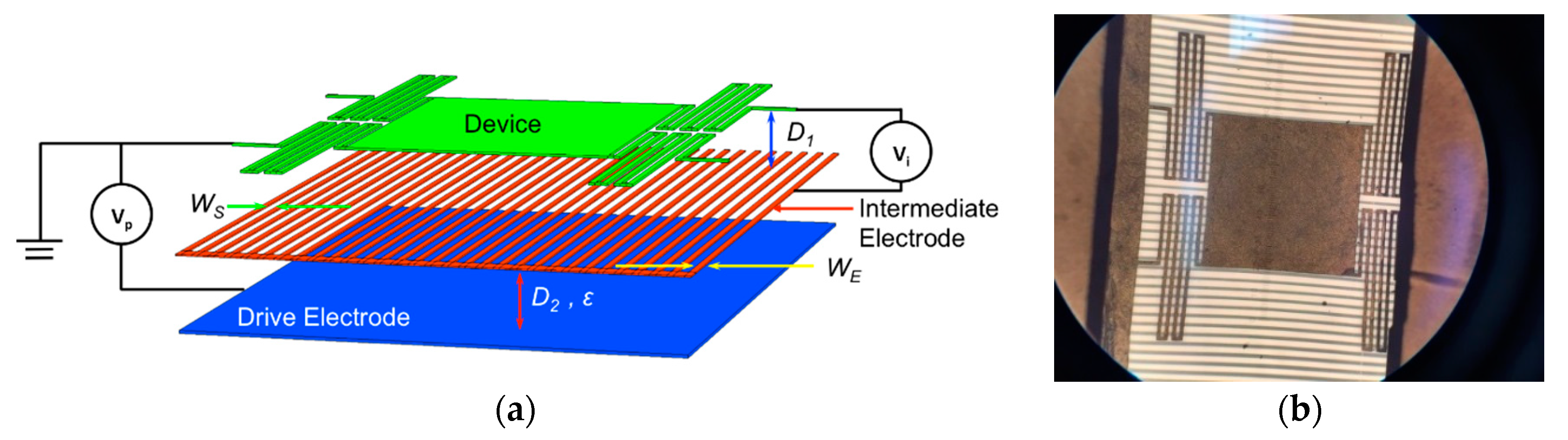
A novel tri-electrode topology for the electrostatic actuator was introduced in [
5] that can greatly reduce the controlling voltage. A perforated intermediate electrode (biased to
Vi) is placed between the MEMS and the underlying pull-down electrode (biased to
Vp).
Figure 1a illustrates the tri-electrode topology, and
Figure 1b shows a picture of a fabricated device. The intermediate electrode operates as the variable voltage to provide controllable displacement, while the pull-down electrode remains at a fixed voltage.
2. Tri-Electrode Configuration Modelling
Simulations of the tri-electrode structure were undertaken using COMSOL Multiphysics, to determine a base design having pull-down electrode voltages similar to many traditional MEMS structures.
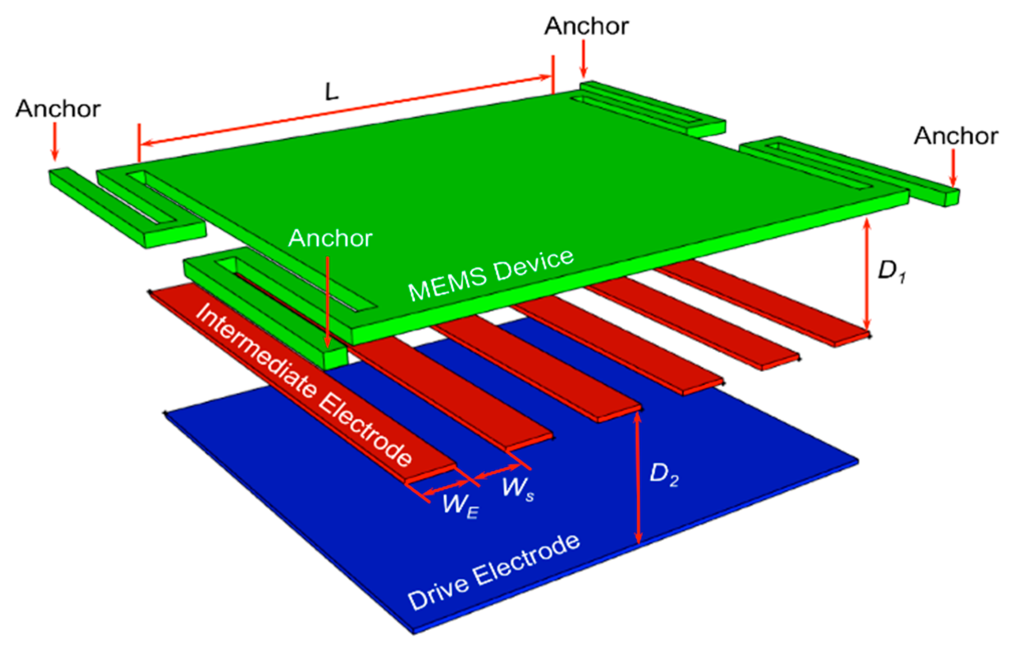
Figure 2 shows the simulated device, with the intermediate electrode having solid (
WE) and perforated elements (
WS) of equal widths.
Table 1 shows the parameters used.
The MEMS device is anchored through the suspending springs, and the system was designed so that in conventional operation a 20 V drive voltage on the drive electrode displaces the MEMS ~4.5 µm. A further increase in voltage results in sufficient displacement to cause the pull-in effect. The conventional operation relates to applying bias voltage on the drive electrode only, while leaving the intermediate electrode electrically floating. The blue line in
Figure 3 shows the performance of the conventional operation mode.
The tri-electrode operation mode is enabled by applying a voltage (Vi) on the intermediate electrode with Vp fixed. The red curve shows the scenario with the drive electrode fixed at Vp = 20 V, and the green curve is for Vp = 40 V. The plotted lines show the maximum displacement possible before the pull-in effect occurs in both situations.
3. Results and Discussion
Case 1 with
WE =
WS is shown in
Figure 3a and compares the performances of the tri-electrode mode with the conventional mode. We can see that by using the intermediate electrode as the control electrode, a similar displacement can be achieved with significantly reduced control voltage. For
Vp = 20 V, a
Vi = 7.1 V gives a maximum displacement of 4.62 µm, while the displacement at
Vi = 0 V is 0.13 µm, giving a controllable stroke of 4.49 µm. This stroke is achieved with only 35.5% of the prior drive voltage of 20 V. The full range of displacement would be achieved by making
Vi = −1.6 V, giving a minimum displacement of 0.049 µm. In this situation, the controllable stroke is 4.57 µm.
When Vp is increased to 40 V, the needed voltage on the intermediate electrode is reduced. For this case, the maximum displacement of 4.39 µm occurs at Vi = 4.8 V, which is 24% of the original needed voltage of 20 V. In this case, the minimum displacement is 0.22 µm at Vi = −3.2 V, giving a controllable stroke of 4.17 µm.
Case 2 with
WE = 1/3
WS is shown in
Figure 3b. We can see a similar reduction in
Vi corresponding to the maximum displacement for both values of
Vp. For
Vp = 20 V, the maximum displacement is simulated to be 4.40 µm with a
Vi = 7.0 V, while the minimum displacement (0.15 µm) occurs at
Vi = −4.2 V. When
Vp = 40 V, the maximum displacement is simulated to be 3.70 µm with a
Vi = −0.89 V, while the minimum displacement (0.74 µm) occurs at
Vi = −8.4 V.
Based on observation of
Figure 3a,b, it is obvious that the increased
Vp leads to an increased strength of the fringing electric field from the drive electrode. The increased strength of the fringing field has two effects demonstrated in the figure. First, it reduces the required
Vi to reach the maximum displacement of the device before the pull-in. However, it also reduces the controllable range before the pull-in. Second, it pushes the
Vi voltage of the minimum displacement to the negative of the voltage axis, meanwhile increases the minimum displacement.
The comparison between two figures also shows that a reduced WE to WS ratio leads to a wider variation of Vi that is required for the maximum controllable stroke. As the width of the intermediate electrodes shrink, the shielding effect of the intermediate electrode is reduced. The same effect also leads to the reduced maximum displacement before pull-in and increased minimum displacement in case of WE = WS and WE = 1/3 WS with Vp = 40 V.
4. Fabrication of a Prototype and Experimental Demonstration
A fabricated prototype, which is shown
Figure 1b, employs a spring supported MEMS located D1 = ~35 µm over the intermediate electrode. Performance was evaluated as a conventional electrostatic actuator and in tri-electrode mode.
Figure 4a shows that in conventional operation a voltage
VS on the pull-down electrode is required to enable a displacement of ~10 µm.
Figure 4b shows the tri-electrode mode providing a similar controllable stroke, but requiring only
Vi = ± 0.17
VS on intermediate electrode while the pull-down electrode is held fixed at
Vp = 5.81
VS. It should be mentioned that without the pull-down electrode biased (
Vp = 0 V), the intermediate electrode itself biased to
Vi = 0.17
VS enabled only ~1 µm motion.
5. Conclusions
In this paper, we carried out a successful experimental demonstration of the drive (control) voltage reduction of the tri-electrode topology. Furthermore, we investigated the effect of various drive voltage (Vp) for two different perforation width (WE vs. WS) ratios. It is apparent from the that the increased drive voltage can reduce the needed control voltage (Vi) required to achieve the maximum displacement, however, at the same time reduces the value of the maximum controllable stroke. Reducing the WE to WS ratio also reduces the maximum controllable stroke, and increases the range of the needed control voltage (Vi) required to achieve a given controllable stroke.
Author Contributions
Y.Z. undertook the simulation and experimental work with C.S., and the writing of the paper and date analysis. L.S. and G.B. provided guidance on the design of the MEMS structures under consideration.
Acknowledgments
This research was financially supported by the Natural Research Council (NRC) of Canada, and the Natural Sciences, and Engineering Research Council (NSERC) of Canada.
Conflicts of Interest
The authors declare no conflict of interest.
References
- Shmulevich, S.; Rivlin, B.; Hotzen, I.; Elata, D. A gap-closing electrostatic actuator with a linear extended range. J. Microelectromech. Syst. 2013, 22, 1109–1114. [Google Scholar] [CrossRef]
- Sugimoto, T.; Nonaka, K.; Horenstein, M.N. Bidirectional electrostatic actuator operated with charge control. J. Microelectromech. Syst. 2005, 14, 718–724. [Google Scholar] [CrossRef]
- Ren, H.; Wang, W.; Tao, F.; Yao, J. A bi-directional out-of-plane actuator by electrostatic force. Micromachines 2013, 4, 431–443. [Google Scholar] [CrossRef]
- Seeger, J.I.; Crary, S.B. Analysis and simulation of MOS capacitor feedback for stabilizing electrostatically actuated mechanical devices. WIT Trans. Built Environ. 1997, 31, 199–208. [Google Scholar] [CrossRef]
- Zhou, Y.; Shafai, C. Reduction of electrostatic control voltage with a tri-electrode actuator. Proceedings 2017, 1, 282. [Google Scholar] [CrossRef]
| Publisher’s Note: MDPI stays neutral with regard to jurisdictional claims in published maps and institutional affiliations. |
© 2018 by the authors. Licensee MDPI, Basel, Switzerland. This article is an open access article distributed under the terms and conditions of the Creative Commons Attribution (CC BY) license (https://creativecommons.org/licenses/by/4.0/).


