Proceeding Paper

Clamping and Q-Factor Improvement in a Carbon Nanotube Resonator †

Micro- and Nanosystems, Department of Mechanical and Process Engineering, ETH Zurich, 8092 Zurich, Switzerland
*
Author to whom correspondence should be addressed.
Presented at the Eurosensors 2018 Conference, Graz, Austria, 9–12 September 2018.
Proceedings 2018, 2(13), 848; https://doi.org/10.3390/proceedings2130848
Published: 3 December 2018
(This article belongs to the Proceedings of EUROSENSORS 2018)

Abstract

:
This work reports the clamping effects on the performance of a carbon nanotube based nanoresonator. A direct comparison of two different nanotube-clamping geometries on the same nanotube device is presented. The nanotube was mechanically dry transferred and clamped through van-der-Waals forces onto palladium electrodes resulting in a bottom clamped configuration. A 20 nm platinum layer was then selectively deposited on the electrodes through atomic layer deposition resulting in top-bottom clamped configuration. With top clamping, a Q-factor increase of 1.5~2× has been observed accompanied by a decrease in the resonance frequency.

1. Introduction

Clamping losses have been argued to be a significant loss mechanism and especially limiting the performance of nanomechanical resonators [1,2] such as carbon nanotube (CNT) resonators, which suffer from low Q-factors (50–150) at room temperature [3]. The observed Q-factors in nanotubes and other nanoresonators are still largely unexplained and deviate from theoretical expectations [4]. While various reported experimental and theoretical work on CNTs assumed perfect clamping conditions, recently reported experimental investigations suggest clamping instability between CNT and the underlying metal contact [5,6]. Effect of different clamping geometries on carbon nanotube resonators at room temperature and low pressure to our knowledge has not been reported yet. Here, we report the effect on quality factor for the same resonator based on a single walled carbon nanotube (SWCNT) subjected to two different clamping configurations for direct comparison and investigations of clamping associated energy dissipation mechanisms. Raman spectroscopy, resonance measurements and DC transport measurements were performed for the same nanotube device to study the clamping effects.

2. Fabrication and Methods

Our CNT resonator device is based on suspended field effect transistor (FET) architecture (Figure 1) with a designed channel length of 2 µm and channel-gate distance of 275 nm. FET devices were fabricated with silicon as device layer and palladium as source (S), drain (D) and gate (G) electrodes. Silicon nitride was used as a sandwiched layer and was deposited through plasma enhanced chemical vapor deposition (PECVD). This served as electrical insulation between silicon and palladium. The trench depth for gate electrode was etched through reactive ion etching (RIE) and palladium electrodes were evaporated through lift-off process [7]. The nanotubes were grown on a separate designated silicon chips and then mechanically dry-transferred [8] onto FET electrodes as reported in [5]. The nanotube is clamped down mechanically onto the palladium electrodes due to van-der-Waals forces resulting in a bottom clamped configuration. To exploit the same nanotube device for clamping effects, a 20 nm platinum layer was selectively deposited onto the metal electrodes through atomic layer deposition (ALD) [7,9]. This resulted in a top-bottom clamped configuration as shown in Figure 1e. The device was characterized (appendix A) by non-destructive Raman spectroscopy (Figure 1b) and CNT length of 2.2 µm and diameter of 2.4 nm (from radial breathing mode-RBM [10]) were obtained. The CNT-FET transfer characteristics reveals a small bandgap semiconducting (SGS) behavior. The dynamic response of CNT resonance was characterized through RF mixing technique [5] at room temperature (298 K) and vacuum (10−4 mbar).

3. Experiment and Results

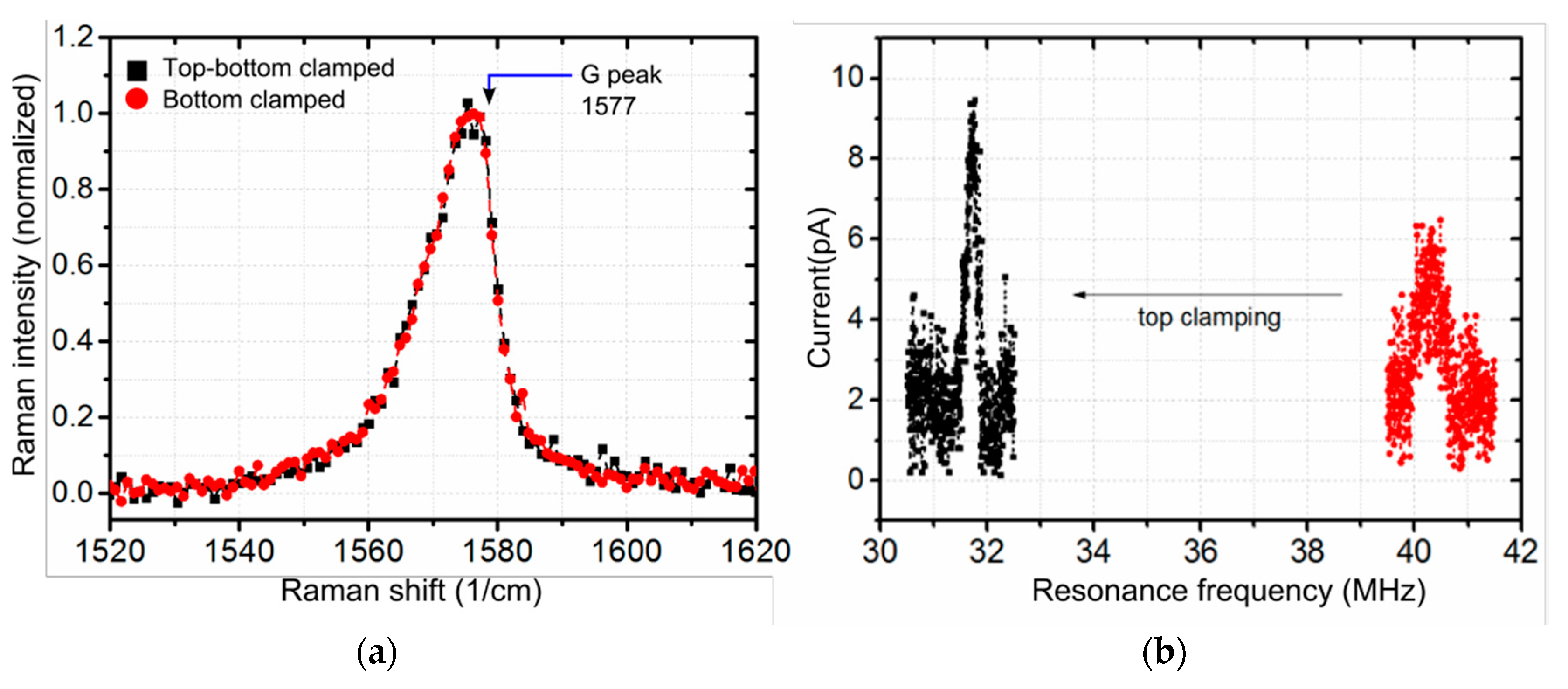
We investigated the Raman spectrum of the suspended nanotube before and after top clamping for a qualitative analysis as shown in Figure 2a. For both clamping configurations, Raman spectroscopy showed no significant change in G-peak position and broadening and no detectable D (defect) peak for the nanotube after the platinum ALD process suggesting no significant change in stress and structural quality. An initial resonance frequency of 40.2 MHz for bottom clamped device decreased to 31.5 MHz as a result of top clamping as shown in Figure 2b.
The direct comparison on Q-factor for top-bottom clamped vs bottom clamped device shows ~1.5–2× enhancement as shown in Figure 3 despite of resonance frequency decrease. The improvement was observed for various DC gate biases. Dependence of Q factor on DC gate bias was also visible with no significant increase in resonance frequency. The spectral broadening with increasing magnitude of DC bias could be attributed to increase in electrostatic noise; however, the off-resonance current shows no DC bias dependence. This observed dependence was attributed to amplitude dependent broadening as reported previously in carbon nanotube resonators [11].

4. Discussion and Conclusions

From the direct comparison of the same nanotube device, the observed enhancement in Q-factors suggests the influence of external mechanisms associated to clamping rather than internal mechanisms. Under the assumption of weak nature of clamping [5,6] resulting in imperfect boundary conditions, energy dissipation might arise from frictional losses due to sliding between the nanotube und the metal electrode or could be assisted though phonon-phonon interactions and edge vibrations as observed in graphene resonators [12]. The observation of amplitude dependent damping might suggest the role of geometric nonlinearities in energy dissipation mechanisms. The simultaneous increase of Q-factors and decrease in resonance frequency also requires further investigations on the effect of top metallization.

Author Contributions

L.K. conceived, designed and performed the experiments; L.V.J. fabricated the CNT FET devices and developed process recipes for selective platinum ALD; M.H. performed Raman spectroscopy; C.I.R. and M.H. assisted in analyzing the data; L.K. wrote the manuscript. C.H. initiated and supervised the research and reviewed the manuscript.

Acknowledgments

This work would like to acknowledge Sebastian Eberle for the support in CNT growth and the clean room facility-Binnig and Rohrer Nanotechnology Center (BRNC) at IBM and FIRST CLA at ETH Zurich for equipment accessibility and helpful discussion. We would also like to kindly acknowledge the Swiss National Science Foundation (SNSF-Project No. 153292) for the funding support.

Conflicts of Interest

The Author declares no conflict of interest in the reported research results. The founding sponsors had no role in the design of the study; in the collection, analyses, or interpretation of data; in the writing of the manuscript, and in the decision to publish the results.

Appendix A

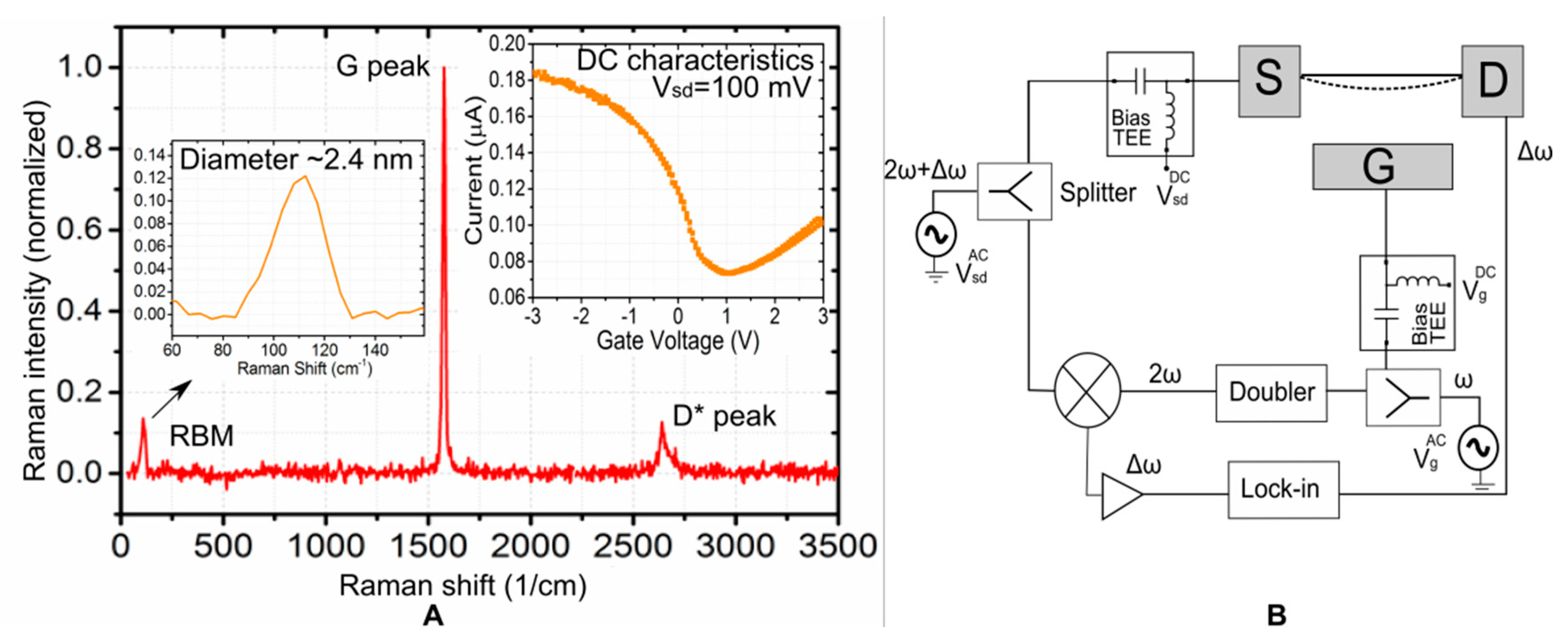
As grown nanotubes were characterized by non-destructive Raman spectroscopy to shortlist a nanotube with undetectable D peak and then dry transferred onto the FET device. Raman spectrum was measured using a 532 nm laser excitation before and after the dry transfer process for structural quality. Raman image and radial breathing mode (RBM) were used to extract the dimensional parameters of nanotube as shown in Figure A1.
DC measurement identified the tube to be small bandgap semiconducting (SGS) tube, which are reported to have high Gauge factors. The mechanical resonance was hence characterized by using a 2ω method to measure the piezoresistive current as shown in Figure A1B.
Figure A1. (A) CNT characteristics obtained from Raman spectroscopy and DC measurement. (B) Experimental Setup for measuring the piezoresistive current.
Proceedings 02 00848 g0a1

References

  1. Jensen, K.; Peng, H.B.; Zettl, A. Limits of Nanomechanical Resonators. In Proceedings of the International Conference on Nanoscience and Nanotechnology, Brisbane, Australia, 3–7 July 2006. [Google Scholar]
  2. Ko, J.H.; Jeong, J.; Choi, J.; Cho, M. Quality factor in clamping loss of nanocantilever resonators. Appl. Phys. Lett. 2011, 98, 171909. [Google Scholar] [CrossRef]
  3. Sazonova, V.; Yaish, Y.; Üstünel, H.; Roundy, D.; Arias, T.A.; McEuen, P.L. A tunable carbon nanotube electromechanical oscillator. Nature 2004, 431, 284–287. [Google Scholar] [CrossRef] [PubMed]
  4. Imboden, M.; Mohant, P. Dissipation in nanoelectromechanical systems. Phys. Rep. 2014, 534, 89–146. [Google Scholar] [CrossRef]
  5. Kumar, L.; Jenni, L.V.; Haluska, M.; Roman, C.; Hierold, C. Mechanical stress relaxation in adhesively clamped carbon nanotube resonators. AIP Adv. 2018, 8, 25118. [Google Scholar] [CrossRef]
  6. Aykol, M.; Hou, B.; Dhall, R.; Chang, S.-W.; Branham, W.; Qiu, J.; Cronin, S.B. Clamping Instability and van der Waals Forces in Carbon Nanotube Mechanical Resonators. Nano Lett. 2014, 14, 2426–2430. [Google Scholar] [CrossRef] [PubMed]
  7. Jenni, L.V.; Haluska, M.; Hierold, C. Selective metallization and passivation of dry-transferred carbon nanotubes in field-effect transistors. In Proceedings of the 2018 IEEE Micro Electro Mechanical Systems (MEMS), Belfast, UK, 21–25 January 2018; pp. 479–482. [Google Scholar]
  8. Muoth, M.; Hierold, C. Transfer of carbon nanotubes onto microactuators for hysteresis-free transistors at low thermal budget. In Proceedings of the IEEE 25th International Conference on Micro Electro Mechanical Systems (MEMS), Paris, France, 29 January–2 February 2012; pp. 1352–1355. [Google Scholar]
  9. Mackus, A.J.M.; Verheijen, M.A.; Leick, N.; Bol, A.A.; Kessels, W.M.M. Influence of Oxygen Exposure on the Nucleation of Platinum Atomic Layer Deposition: Consequences for Film Growth, Nanopatterning, and Nanoparticle Synthesis. Chem. Mater. 2013, 25, 1905–1911. [Google Scholar] [CrossRef]
  10. Meyer, J.C.; Paillet, M.; Michel, T.; Moréac, A.; Neumann, A.; Duesberg, G.S.; Sauvajol, J.L. Raman Modes of Index-Identified Freestanding Single-Walled Carbon Nanotubes. Phys. Rev. Lett. 2005, 95, 217401. [Google Scholar] [CrossRef] [PubMed]
  11. Eichler, A.; Moser, J.; Chaste, J.; Zdrojek, M.; Wilson-Rae, I.; Bachtold, A. Nonlinear damping in mechanical resonators made from carbon nanotubes and graphene. Nat. Nanotechnol. 2011, 6, 339–342. [Google Scholar] [CrossRef] [PubMed]
  12. Takamura, M.; Okamoto, H.; Furukawa, K.; Yamaguchi, H.; Hibino, H. Energy Dissipation in Graphene Mechanical Resonators with and without Free Edges. Micromachines 2016, 7, 158. [Google Scholar] [CrossRef] [PubMed]
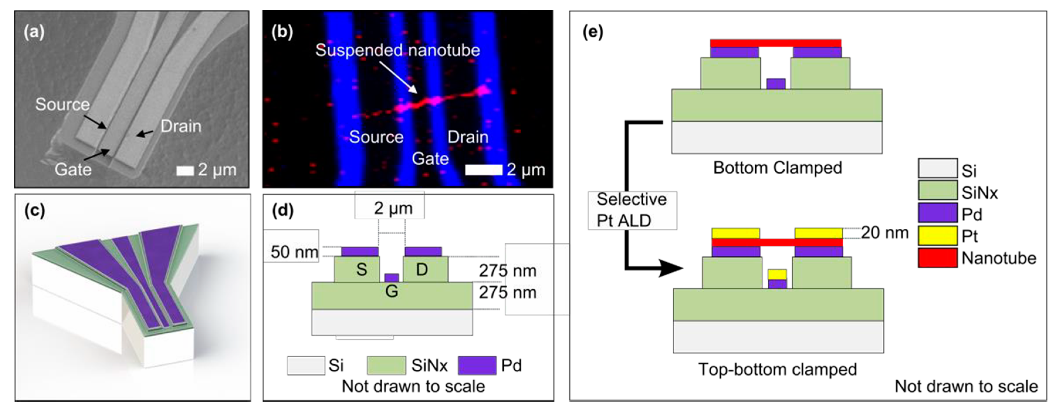
Figure 1. (a) Scanning electron microscope (SEM) image representing a FET based device with bottom gate electrode; (b) Raman image of suspended carbon nanotube (red) resonator device obtained after dry transfer; (c,d) Schematic of device and it’s cross-section; (e) Schematic of two different clamping geometries with the same nanotube device investigated in this work.
Proceedings 02 00848 g001
Figure 2. (a) Raman spectra of the suspended nanotube measured for two different clamping geometries; (b) Resonance frequency downshift from 40.2 MHz to 31.5 MHz after top clamping.
Proceedings 02 00848 g002
Figure 3. Q-factor (middle) extracted from Lorentzian curve fit (left, right) at different DC gate bias for bottom clamped (left) and top-bottom clamped (right). The resonance frequency did not change significantly. Each box represents Q-factors obtained from five measured spectral responses measured at Vgac = 18 mV, Vsdac = VsdDC = 10 mV.
Proceedings 02 00848 g003
Publisher’s Note: MDPI stays neutral with regard to jurisdictional claims in published maps and institutional affiliations.