1. Introduction
Magnetic fluids are used in different application fields to realize sealing, active damping and sensors [
1,
2,
3,
4]. The latter exploit unique advantages provided by these materials, such as robustness against mechanical shocks, sensor performance adaptability and decoupling between electrical and ferrofluid based parts, which often represent the disposable and low cost part of the system [
5].
Among ferrofluid based devices, a strong interest has been manifested in the development of efficient inertial sensors, with particular regards to inclinometers, as demonstrated by a rich state of the art [
6,
7].
This paper presents an optical inclinometer exploiting a ferrofluid mass, which uses an InfraRed readout strategy, a magnetic shaping system, which assures an optimal shape to the ferrofluid mass, and a dedicated paradigm to process signals provided by the IR detectors, with the aim of defining a calibration model relating the inclinometer output quantity to the imposed tilt.
A first attempt to implement a ferrofluid based inclinometer exploiting an InfraRed (IR) readout strategy is presented in [
8]. The sensor is based on the shifting of the ferrofluid mass along a glass channel due to the imposed tilt. The mass is retained by the action of a magnetic field which acts like a spring, while its position is measured by an array of IR detectors which detect the obscuring effect of the ferrofluid mass during in different steady state position inside the channel. Main limitations of the proposed configuration are related to the IR system configuration mainly due to the illuminating device positioned in one of the two channel ends, the shape of the ferrofluid mass, as well as the paradigm adopted to process signals coming from the array of IR detectors.
The sensing methodology discussed through this paper aims to fix drawbacks of previous solutions [
8], mainly concerning the readout architecture and signal post processing.
The working range of the inclinometer developed is [−15°–15°]; the sensor accuracy and resolution are 0.61° and 0.005°, respectively. Moreover, a span to resolution ratio of 6 × 10³ has been obtained.
2. The Device Developed
In the following details related to the realization of the ferrofluid based tilt sensor are given, with particular regards to hardware realization and paradigms developed to process data provided by the array of IR detectors.
2.1. The Experimental Setup
The sensor consists of a glass pipe with a diameter of 5 mm, a mass of HF1 Ferrofluid by Ferrotec with a volume of 0.011 mL and an IR system to monitor the position of the ferrofluid mass. The IR system consists of a SFH 487 LED facing an array of SFH PFA 309 Phototransistors, by Osram Opto Semiconductor. The glass pipe is positioned in between the Led and the Phototransistors. The detectors array length is 2.5 cm, which is compliant with the expect ferrofluid mass shift, according to the tilt operating range of interest. The IR LED has been selected to suitably assure illumination of the whole optical array. The real view of the device presented in this paper is shown in
Figure 1.
The mass of ferrofluid is retained towards its rest position by using a magnetic spring-like system [
6]. When a tilt is applied to the system, the equilibrium between the magnetic retaining force and the vertical component of the gravity force, acting on the ferrofluid mass along the main pipe axis, defines a new position of the mass, which is detected by the IR system.
The magnetic shaping system shown in
Figure 1 has been used to assure the formation of a cone shaped mass along its whole range of shift inside the pipe [
9]. To such aim an optimal distance of 2.2 cm between the permanent magnet and the glass pipe has been experimentally estimated.
The volume of the ferrofluid mass has been fixed to properly implement the tilt to optical conversion mechanism, which relies in the partial or complete obscuration of consecutive couples IR detectors for increasing values of the applied tilt. In particular, in order to assure the ferrofluid mass covers the surface of a single receiver, the cone base radius is assumed equal to that of a photodetector r = 0.145 cm and the height equal to the diameter of the pipe h = 0.5 cm. Under this condition, the following volume of the ferrofluid mass has been estimated:
2.2. The Experimental Setup
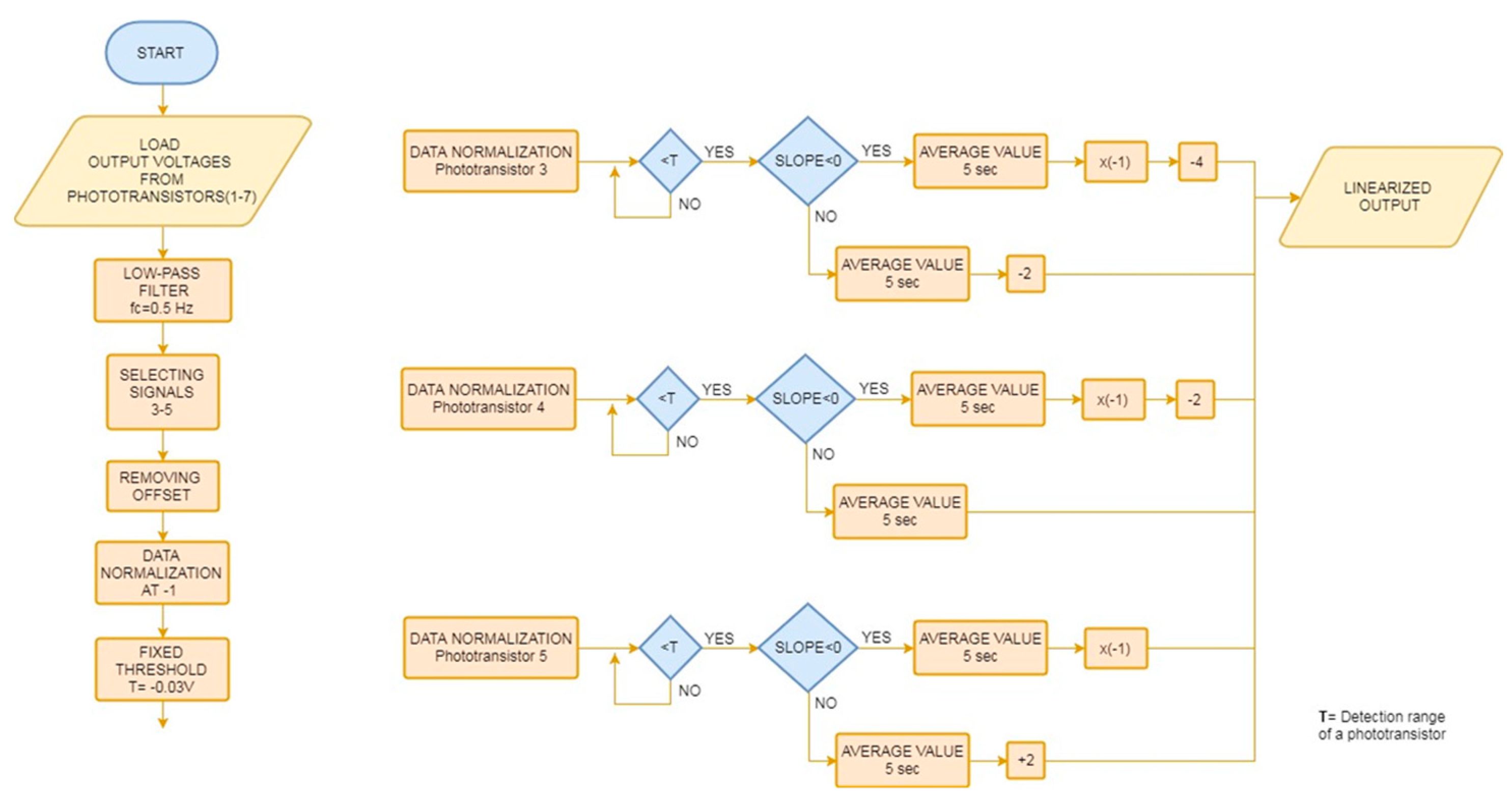
Signals provided by IR detectors are processed by the paradigm shown in
Figure 2, which performs signal normalization and prost-processing of each single detector output according to signal itself characteristic. A low pass-filtering at 0.5 Hz and normalization are implemented for the sake of signal pre-processing. In case a normalized signal exceeds a prefixed threshold offset and sign operations are implemented, as shown in the flow diagram in
Figure 2b. All processed signals are then summed to generate the output quantity of the sensor.
3. The Device Characterization
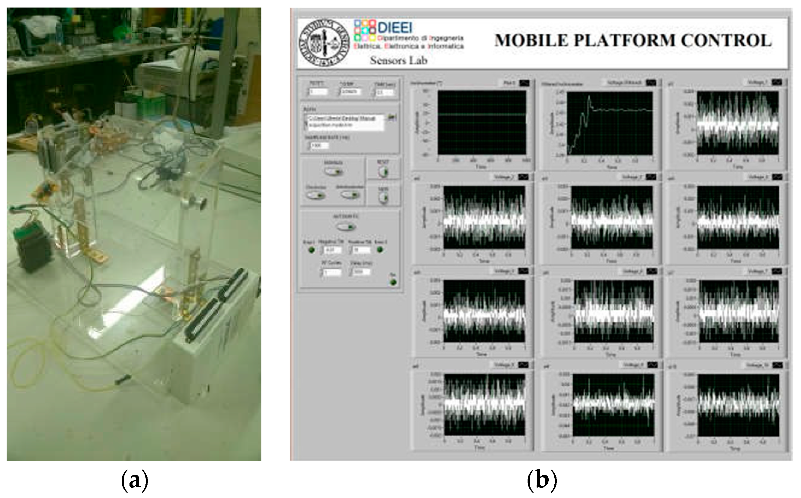
In order to investigate the sensor behavior a dedicated platform has been implemented which allows to apply consecutive tilts to the sensor, to acquire signals provided by the optical system and to implement the paradigm above mentioned.
The platform, shown in
Figure 3a, consists of a stepper motor controlled through a LabVIEW interface, shown in
Figure 3b, which is used to force increasing tilt to the ferrofluid inclinometer. The reference inclinometer SCA61T-FA1H1G has been used to perform an independent measurement of the imposed tilt during the device characterization.
The same LabVIEW environment is exploited to acquire signals provided by the IR detectors and the reference inclinometer, using a Data Acquisition board by National Instruments. The data acquisition sampling rate was fixed to 1 kHz.
A typical behavior of pre-processed signals provided by IR detectors as a function of the applied tilt is shown in
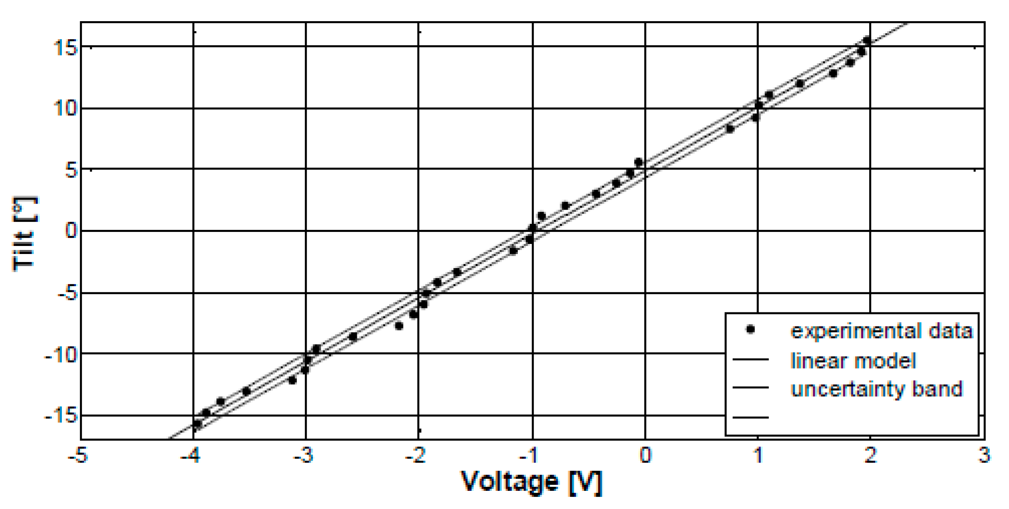
Figure 4. As it can be observed, for increasing values of the applied tilt, IR detectors are consecutively obscured by the presence of the mass of ferrofluid shifting along the gals pipe. Results obtained by applying the signal processing paradigm are shown in
Figure 5, which results in the calibration diagram of the sensor including the uncertainty bandwidth estimated in 1 σ level. A linear model has been used to interpolate measurement data by a best fitting procedure.
The sensor responsivity is 0.19 V/°, while a nominal resolution of 0.005° has been estimated as the ratio between the standard deviation of the output signal in case of a null tilt and the sensor responsivity.


