Proceeding Paper

Experimental Demonstration of Stray-Field Immunity beyond 5 mT for an Automotive-Grade Rotary Position Sensor †

1
Melexis, 2022 Bevaix, Switzerland
2
Melexis, 8900 Ieper, Belgium
3
Melexis, 3980 Tessenderlo, Belgium
*
Author to whom correspondence should be addressed.
Presented at the Eurosensors 2018 Conference, Graz, Austria, 9–12 September 2018.
Proceedings 2018, 2(13), 763; https://doi.org/10.3390/proceedings2130763
Published: 10 December 2018
(This article belongs to the Proceedings of EUROSENSORS 2018)

Abstract

:
This paper experimentally demonstrates the stray-field robustness capability of a novel Hall-based rotary position sensor concept (Huber, S., et al, 2018). The sensor targets safety-related automotive applications, for example powertrain and power steering. In these applications, the safety requirement specifies a maximum stray-field induced error of 0.4°. Therefore, the robustness in corner cases needs to be assessed. We demonstrate the stray-field immunity in multiple corner cases for temperature from −40 °C up to 160 °C and over lifetime. The impact of a uniform 5 mT stray field over all conditions (3σ) is shown to be less than 0.25°. The fully-integrated automotive-qualified sensor is implemented in a 0.18-μm CMOS technology, and achieves 0.7° of angular accuracy.

1. Introduction

Magnetic stray fields are naturally present in modern vehicles, especially electrified cars. Large magnetic stray fields in the order of 1 mT have been measured in electrified cars [1]. The most critical location is naturally close to the high-voltage (HV) cables between the battery and the electrical motor. Legacy magnetic sensors, which are ubiquitous in modern cars [2], are corrupted by such a high stray field. Consider for example a legacy magnetic sensor operating with a signal amplitude of 40 mT near a wire carrying 400 A (a typical specification). The stray field drops slowly with the distance as 1/r (see Figure 1a). At a distance r = 30 cm, the field (B~0.3 mT) is still large enough to introduce a significant angular error (~0.4°). Practically, this creates an exclusion zone (see Figure 1b) of about 30 cm away from any HV cables for legacy Hall sensors severely limiting their practicality. Inductive sensors, on the other hand, are naturally insensitive to low-frequency stray fields. However, they require more space due to the overhead of the discrete coils. To address the stray-field challenge in Hall-based sensors, we developed a new gradiometric Hall sensor concept described in our companion paper [3].

2. Materials and Methods

The gradiometric concept is implemented in a CMOS chip [4] with an appropriate integrated magneto-concentrator (IMC). The sensor is sensitive to magnetic field gradients in the plane of the chip. In production tests, the sensors are trimmed for optimum stray-field rejection by adjusting the sensitivities of the individual Hall elements. The stray-field rejection is thus limited by residual mismatch. To assess the robustness of the concept, we selected corner parts from a production lot with the highest residual mismatch. The sensors were subjected to a uniform stray field of 5 mT generated by a Helmotz coil (corresponding to a magnetic field strength H of 4 kA/m). The signal of approximately 21 mT/mm was generated by a 4-pole magnet at nominal airgap. The stray-field induced error is calculated as the difference of the output angle reported by sensor in presence and absence of the stray field.
θ err , stray = θ out ( B stray = 5   mT ) θ out ( B stray = 0 )
For evaluating the sensor response to a nearby current, the sensors were mounted on a rotating stage near a busbar carrying 400 A. This configuration generates an inhomogeneous stray field (see the stray-field gradient dB/dr in Figure 1a).

3. Results

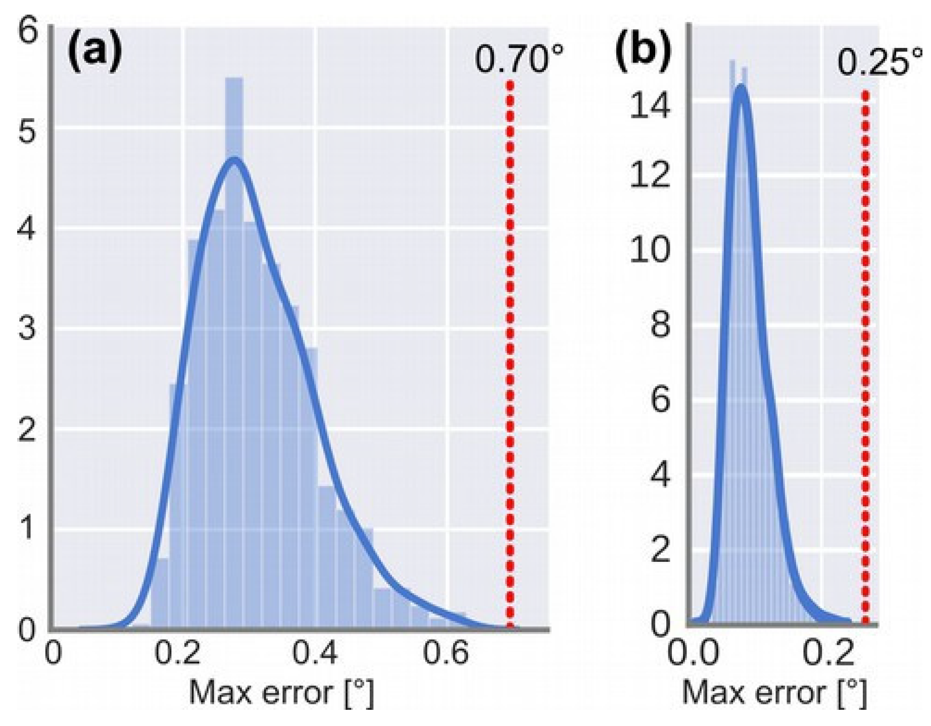
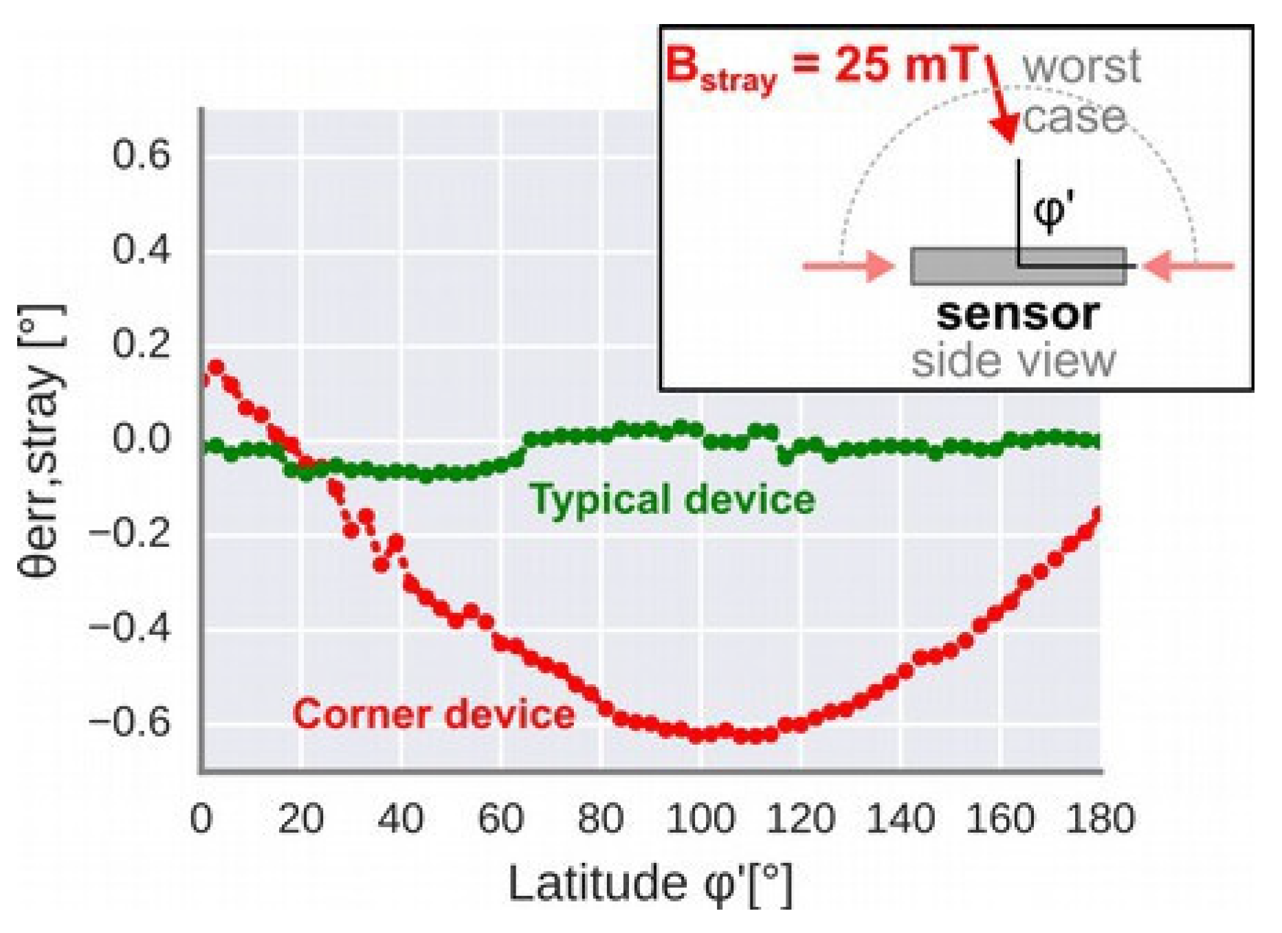
3.1. Impact of Uniform Stray Fields

Figure 2a shows that the accuracy, limited by thermal drift, is 0.7° in the absence of stray field. Figure 2b shows the impact, for about 600 chips, of a 5 mT uniform stray field as per automotive standard (ISO 11452-8). The stray-field induced error is less than 0.25° for the whole population. To investigate the residual stray-field parasitic sensitivity, we characterized (Figure 3) a corner device from the extreme of the production distribution. According to the production test, this device exhibited the worst rejection of out-of-plane field. A stray field of 25 mT, 5× larger than the typical specification to magnify the effect, was rotated out-of-plane with respect to the sensor. As expected, the maximum error was measured when the stray field was almost orthogonal to the sensor surface. The in-plane case was more favourable (data not shown). For typical devices, the stray-field induced errors were below the noise level.

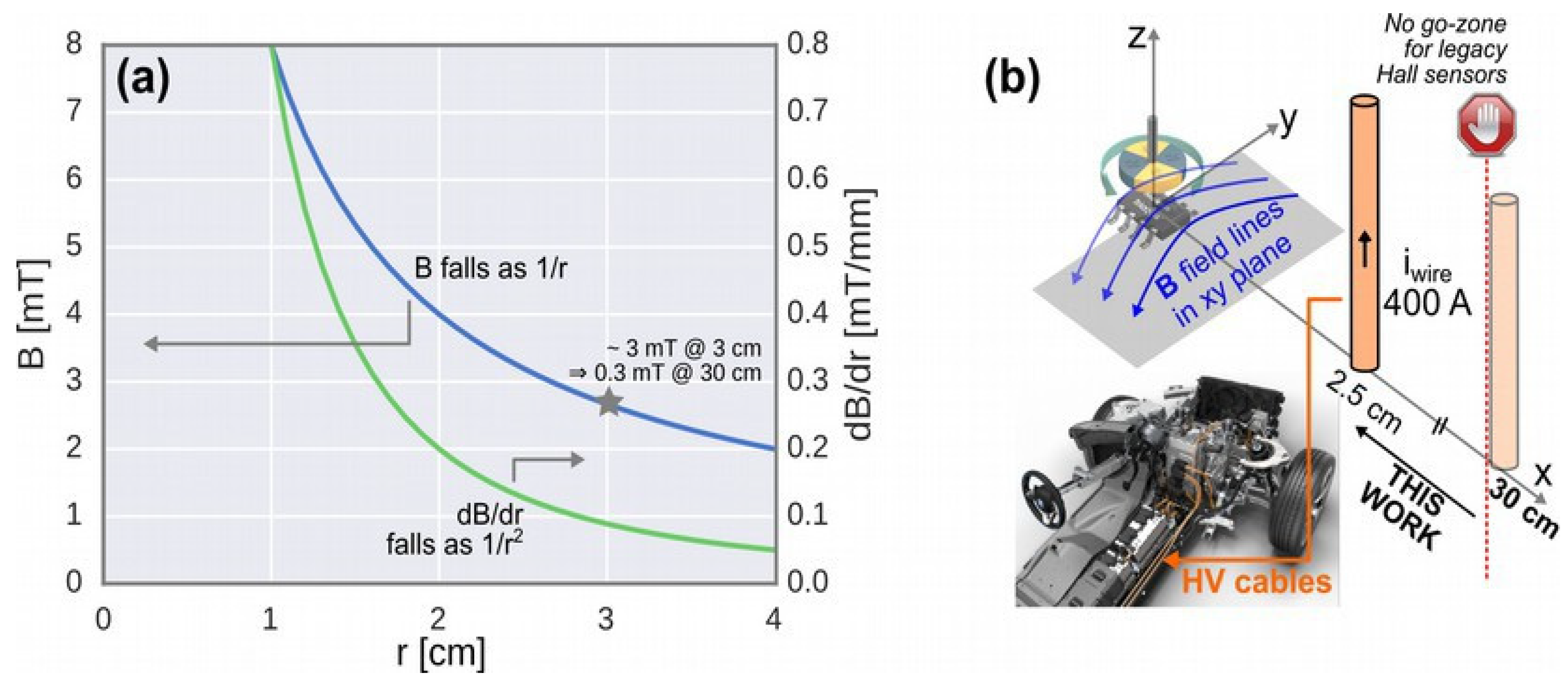
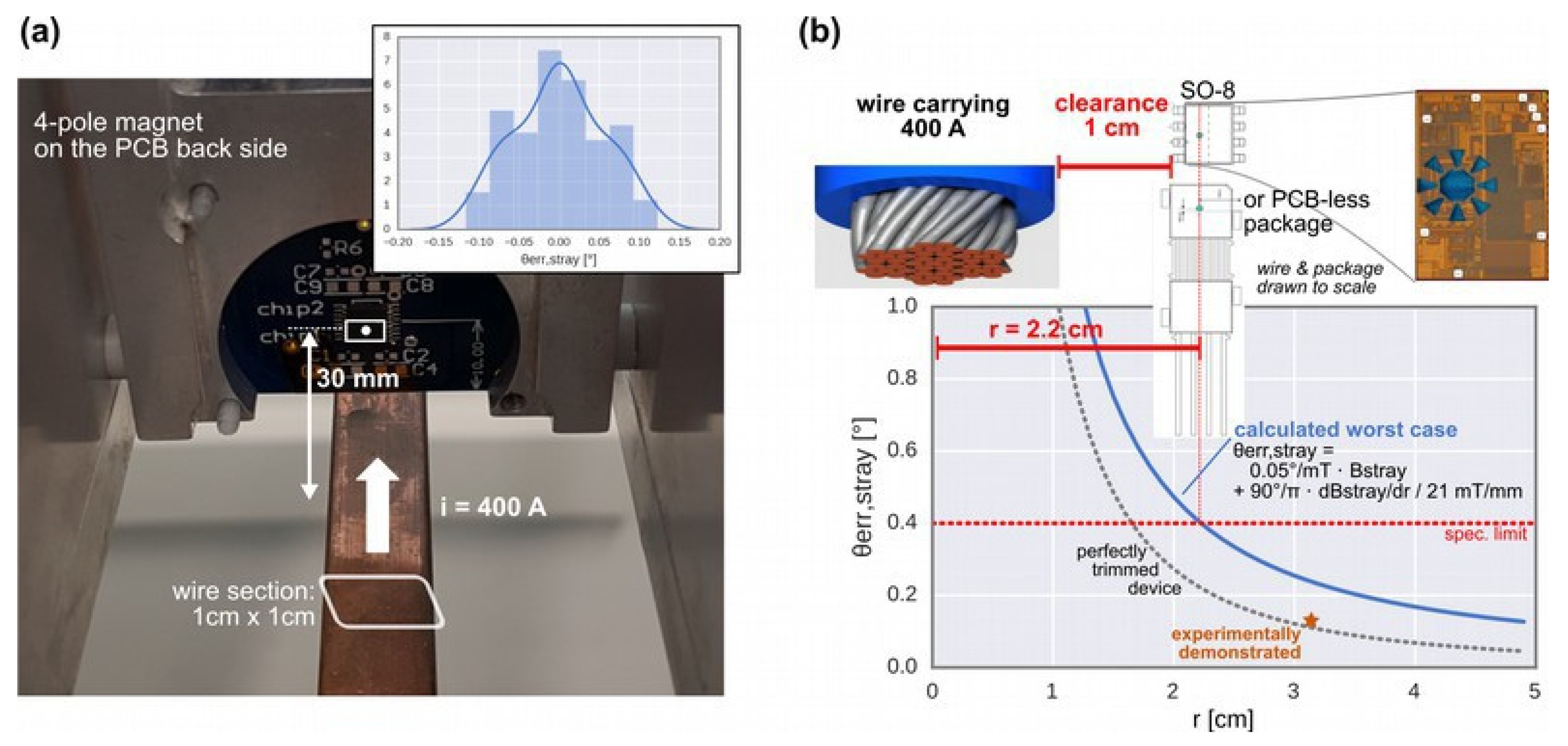
3.2. Impact of Current-Carrying Wire

Additionally, we investigated the more practical case of non-uniform stray-fields, with a field gradient similar to the useful signal. The sensors were mounted on a multi-axis rotating stage above a busbar carrying 400-A (see Figure 4a). The orientation shown in the picture is the worst case, in which the sensor is affected by the stray-field gradient in the sensor plane. The signal (21 mT/mm) is generated by a 4-pole magnet mounted on the backside of the PCB. The stray-field induced error was shown to be less than 0.15° at 30 mm of distance. The inset in Figure 4a shows the histogram of the measured errors of a corner device over roughly 100 different orientations while maintaining a 30-mm center-to-center distance. We derived an equation (Figure 4b) for the total stray-field induced error, with error terms arising from the average stray field and its gradient. With just 1-cm of clearance with respect to the wire, the error remains below 0.4° even in the worst case.

4. Conclusions

In summary, we demonstrated that the angular position signal remains robust even at just 1-cm of clearance with respect to a wire carrying 400 A of current. This is an improvement by more than an order of magnitude with respect to traditional Hall sensors. The fully-integrated automotive-qualified sensor is implemented in a 0.18-μm CMOS technology, and achieves 0.7° of accuracy. This extends the state of the art for Hall-based sensors. Moreover, it is competitive with inductive solutions, and even outperforms them in terms of compactness.

Conflicts of Interest

The authors declare no conflict of interest.

References

  1. Karabetsos, E.; Kalampaliki, E.; Tsanidis, G.; Koutounidis, D.; Skamnakis, N.; Kyritsi, T.; Yalofas, A. EMF measurements in hybrid technology cars. In Proceedings of the 6th International Workshop on Biological Effects of Electromagnetic Fields, Bodrum, Turkey, 10–14 October 2010. [Google Scholar]
  2. Granig, W.; Hartmann, S.; Köppl, B. Performance and Technology Comparison of GMR Versus Commonly used Angle Sensor Principles for Automotive Applications. SAE Tech. Pap. 2007. [Google Scholar] [CrossRef]
  3. Huber, S.; Burssens, J.-W.; Dupré, N.; Dubrulle, O.; Bidaux, Y.; Close, G.; Schott, C. A Gradiometric Magnetic Sensor System for Stray-Field-Immune Rotary Position Sensing in Harsh Environment. Proceedings 2018, 2, 809. [Google Scholar] [CrossRef]
  4. Leroy, S.; Rigert, S.; Laville, A.; Ajbl, A.; Close, G.F. Integrated Hall-Based Magnetic Platform for Position Sensing. In Proceedings of the ESSCIRC 2017—43rd IEEE European Solid State Circuits Conference, Leuven, Belgium, 11–14 September 2017; pp. 360–363. [Google Scholar]
  5. AMS. AS5171: High-Resolution On-Axis Magnetic Angular Position Sensor. Datasheet. June 2016. Available online: https://ams.com/as5171 (accessed on 8 October 2017).
  6. IDT. ZMID520xMROT36001 Rotary Application Module User Manual. December 2017. Available online: https://www.idt.com/document/man/zmid520xmrot36001-application-module-user-manual (accessed on 10 February 2018).
Figure 1. (a) Magnetic field and field gradient as a function of distance r to a wire carrying iwire = 400 A. (b) In legacy Hall sensors, this generates an exclusion zone around the high-voltage cables in electrified cars. Photo is from BMW i8.
Proceedings 02 00763 g001
Figure 2. Distributions of angle errors for roughly 600 chips from 3 lots after high-temperature operating life (HTOL) qualification tests. For each chip, the maximum error is reported over all conditions: stray-field orientation, magnet mechanical angle, temperature, and lifetime. (a) Angle thermal and lifetime drift in the absence of stray field. (b) Additional stray-field induced angle error (applied stray field is 5 mT).
Proceedings 02 00763 g002
Figure 3. Stray-field induced error for a corner device (with the worst out-of-plane rejection out of several thousands devices) at room temperature. A 25-mT stray-field, 5× larger than the typical specification to magnify the effect, is rotated out-of-plane with respect to the sensor. The in-plane case is more favourable (data not shown).
Proceedings 02 00763 g003
Figure 4. (a) Experimental setup to expose the sensor to a nearby high-power current-carrying wire. (b) Stray-field induced error vs distance: model and result.
Proceedings 02 00763 g004
Table 1. Competing products.
ProductAngle AccuracyStray-Field Immunity
Hall sensors
This work<0.7°>5 mT
ams AS5171 [5]<0.9°>5 mT
Inductive sensors
ZMID520× [6]>0.7° (typ.)Practically infinite
Publisher’s Note: MDPI stays neutral with regard to jurisdictional claims in published maps and institutional affiliations.

