1. Introduction
Detection of hazardous chemicals and greenhouse gases is one among the many challenges of our century. The difficulty lies in the fact that the gases that we need to detect are at trace level, from 1 ppm to a few ppt, with large variations of the concentration in time. The ability to detect several gases with a single detector is a highly desirable feature but is not often met. In addition, to be deployed in the field, gas detectors need to be compact and have a low consumption. A technique meeting all of these requirements is photoacoustic spectroscopy: it presents a wide dynamic range, a very good linearity, and enables multi-species detection with a single device. A new technique called Quartz Enhanced Photoacoustic Spectroscopy (QEPAS) appeared in 2002 [
1] providing a good compromise between compacity and sensitivity. This technique involves the generation of a pressure wave through gas excitation with an amplitude, or wavelength, modulated laser and its detection with a Quartz Tuning Fork (QTF), usually complemented by longitudinal acoustic resonators.
Commercial QTFs are well suited for vacuum use and present two major drawbacks for photoacoustic spectroscopy: a small gap between their prongs as well as a high resonance frequency. Indeed, standard QTFs present low quality factors at atmospheric pressure, and the small gap between the prongs makes it difficult for a laser beam to pass through. Besides, a high resonance frequency will make measurements impossible for gases presenting a fast relaxation time. That is why in [
2,
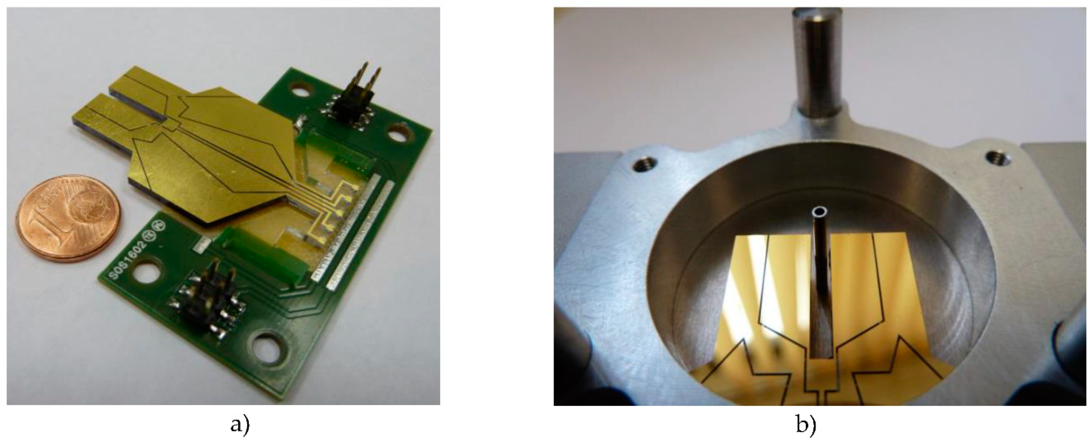
3] we introduced a patented custom QTF (
Figure 1). A surrounding cavity was added to this QTF to confine the acoustic waves emitted by the QTF, providing an unmatched quality factor of 75,000 in air around 21,500 Hz, along with a better acoustic isolation from the environment.
In the following article, we demonstrate the performance of our detector and explain the influence of the dimensions of the acoustic resonators on the quality factor.
2. Experimental Set Up
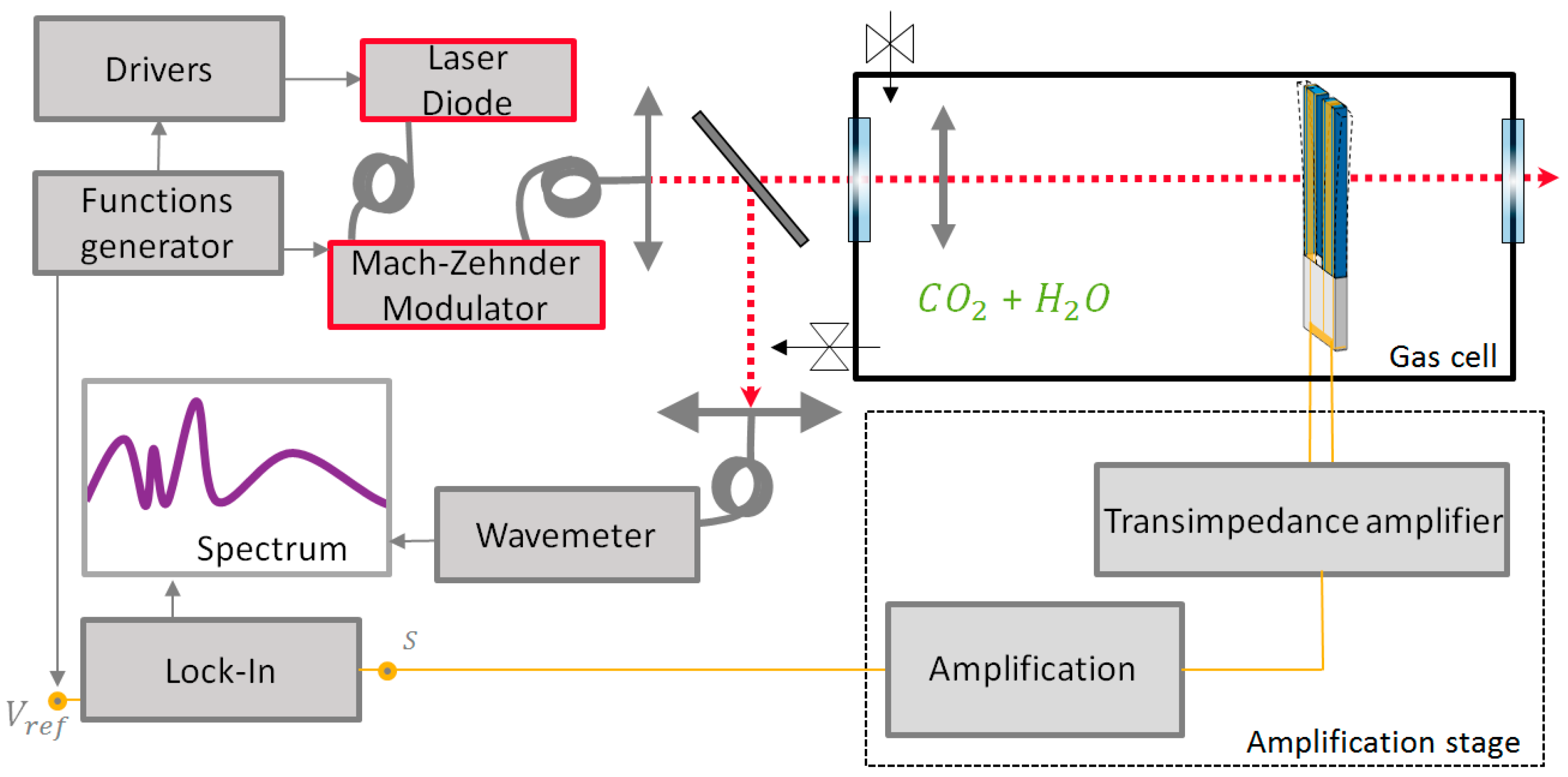
The detection scheme is presented in
Figure 2: we use a sinusoidal wavelength modulated telecom laser diode. The 2f QTF signal is first amplified by means of a low noise transimpedance amplifier, and sent to a lock-in amplifier (Stanford Research SR530) with a 1/16 Hz bandwidth. We used the 6490.5 cm
−1 absorption line of CO2, diluted at 2.7% in nitrogen at atmospheric pressure. The relative humidity of the cell is measured and corresponds to ambient humidity.
The cell contains two AR windows, a lens of focal length 200 mm, an acoustic buffer at λ/4, the tuning fork and its transimpedance amplifier. The cell is filled with the gas mixture before each measurement. The QTF is surrounded by an acoustic cavity allowing in-phase recovery of the emitted acoustic waves [
3]: it is a stainless steel cylinder with height and radius of 16 mm. Two longitudinal acoustic resonators are placed along the laser beam, inside the cavity, these are cut from stainless steel hypodermic needles. For these needles different parameters have been tested: internal diameter, length, position with respect to the QTF stem and penetration depth within the gap between the prongs. We also designed a monolithic cavity including the needles in bulk stainless steel to make the alignment easier.
3. Results
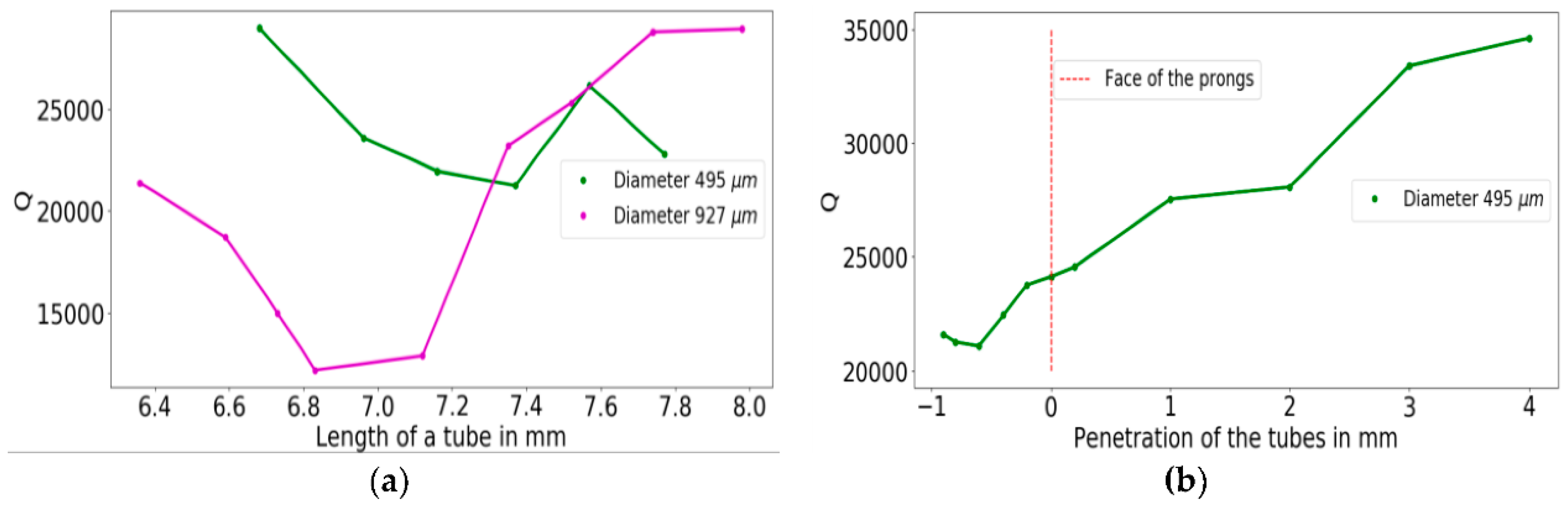
Figure 3 shows the system quality factor over inner diameter, length and penetration depth of the tubes.
When varying the internal diameter of the microresonators, a quality factor minimum is identified, corresponding to a maximum coupling between the acoustic resonators and the QTF and thus to a better signal-to-noise ratio [
3]. In
Figure 3b we see that the Q factor increases with the penetration depth, except between −0.8 to −0.5 mm where it decreases. The reason for this is that the gap between the needles becomes smaller and thus the coupling between the resonators is reduced.
The optimal needles should be 7.3 mm long for an internal diameter of 495 μm and a penetration depth of −0.8 mm. This system presents a Q factor of 21,000 at atmospheric pressure in air.
The sensitivity of the detector can be qualified by a figure of merit, called Normalized Noise Equivalent Absorption (NNEA, detailed definition in [
4]). It represents the minimum detectable absorption, independently from the laser power, the electrical bandwidth and the absorption coefficient of the gas. The NNEA is inversely proportional to the signal-to-noise ratio, which is in turn linked to the quality factor, but in a non-trivial way because of the coupling between the QTF and the microresonators [
3].
By measuring the signal amplitude and the RMS noise within the detection bandwidth we find an optimal NNEA of 3.3 × 10⁻⁸ W·cm−1·Hz−1/2 for our QTF alone and 3.7 × 10⁻⁹ W·cm−1·Hz−1/2 for the QTF with the acoustic cylinder and microresonators. The use of such acoustic resonators greatly reduced the quality factor of our system, from 75,000 to 21,000 for the optimal coupling between the resonators. Nonetheless the addition of such resonators allowed a sensitivity enhancement of about 10.
We also designed the acoustic cavity in a bulk piece of stainless steel with tubes of different sizes, allowing good alignment repeatability. With tubes of diameter 0.7 mm and length 7.3 mm we obtained a NNEA of 7.6 × 10
−9 W·cm
−1·Hz
−1/2, twice the state of the art sensitivity [
5]. The monolithic acoustic cavity could not be machined with microresonators of diameter less than 0.7 mm because it becomes difficult for suppliers to guarantee the tolerances and a good inner surface polishing. Nonetheless, it would be interesting to persevere in this direction to verify that we can obtain the same results than those obtained with the hypodermic needles.
4. Conclusions
A Quartz-Enchanced Photo-Acoustic gas detector with state of the art sensitivity was demonstrated. Its lower detection frequency makes it easier to address gases with faster relaxation times. Also a bigger gap between the prongs (2 mm) should help us obtain a better sensitivity than standard QTFs with the use of larger laser beams in the mid-infrared (typically quantum cascade lasers). We designed and optimized the acoustic cavity and the acoustic resonators, showing the influence of different parameters of these objects. The best geometry for the tubes was found, with 7.3 mm length, 0.5 mm diameter and penetration depth of −0.8 mm inside the QTF’s prongs when using a laser diode at telecom wavelength. We also designed bulk cavities with larger needles diameters and optimal lengths to accomodate for larger laser beams as those emitted by mid infrared lasers.
Future work will include the optimization of the acoustic cavity and adaptation of the design for the use with longwave infrared QCLs.
