Abstract
This work presents the investigation on a MEMS based optomechanical transducer for displacements or vibration regarding its cross-sensitivities to multidirectional input excitations. The principle of the optomechanical transducer is based on the modulation of the light flux passing through one static and one movable micromechanical aperture. This kind of transducer is of increasing interest for MEMS sensors since it has inherent benefits and can compete with state-of- the-art readout concepts regarding its resolution. We have experimentally proven that the sensitivities of the device is 3.3 × 10⁷ V/m in x-direction, 8.23 × 10⁶ V/m in y-direction, while it is negligible in z-direction.
1. Introduction
Micro-electro-mechanical systems (MEMS) have become a common part of everyday life and they are subject to a constant development [1,2]. A critical part of all MEMS based sensors is the readout method, where the most prominent is the capacitive readout [3,4]. Recently, a optomechanical readout was published, which has significant impact on MEMS-based sensors due to its benefits, like galvanic separation, no reaction forces, no restrictions regarding displacement bandwidth, and easy fabrication. It was used to measure the low-frequency Earth tides in a micromechanical seismometer [5]. It was also demonstrated that such a concept can reach displacement resolutions down to 0.86 pm/√Hz [6] and, hence, compete with state-of-the-art transducers like capacitive readouts. Furthermore, the influence of the readout on the damping behavior was investigated [7]. In this work, we focus on the cross-sensitivities of the optomechanical MEMS readout to deflections in various directions. This is crucial for clearer understanding and further improvements of the transducer.
2. Materials and Methods
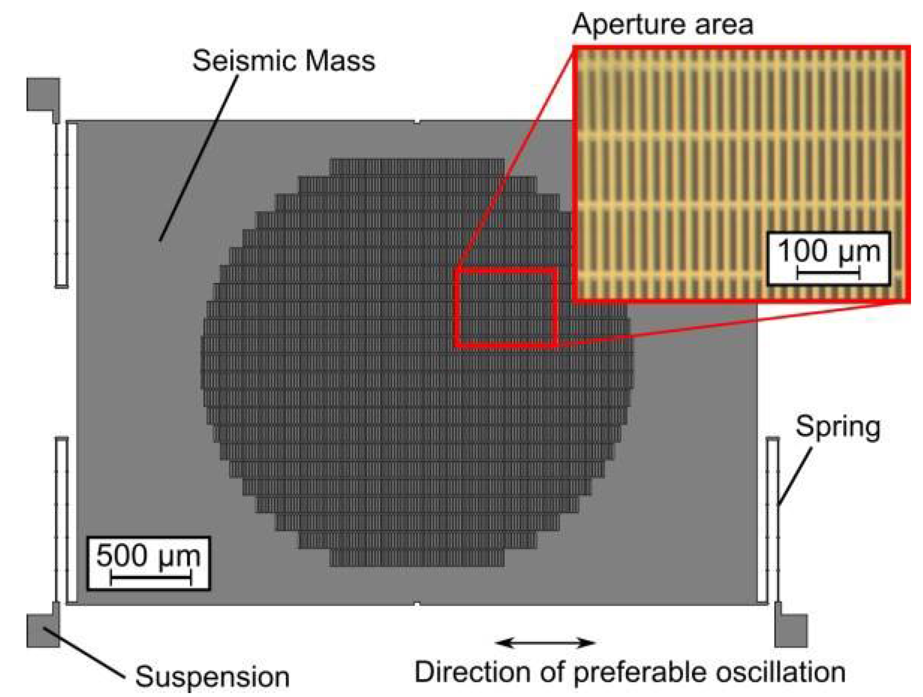
The optomechanical transducer’s output signal is proportional to the light flux modulated by two overlapping aperture arrays. One of the arrays is vapor deposited (chromium) on a fixed glass cover while the other one is etched into a movable seismic mass of a Si MEMS chip. The seismic mass (size A = 4 × 3 mm²) is spring suspended for a preferred deflection direction (Figure 1). The device is micro- fabricated in a silicon-on-insulator wafer, where the thickness of the device layer is d = 45 µm. The glass wafer, holding the stationary apertures, is bonded to the device layer with SU-8 as bonding promoter (Figure 2). The modulated light flux depends on the change of the open area of the aperture which consists of n~2500 rectangular openings (AO = 10 × 100 µm²).

Figure 1.
Schematic of the MOEMS device. A Si spring suspended seismic mass comprises rectangular aperture arrays. A glass cover on top of the structures contains the corresponding stationary chromium array (inlay, optical micrograph).
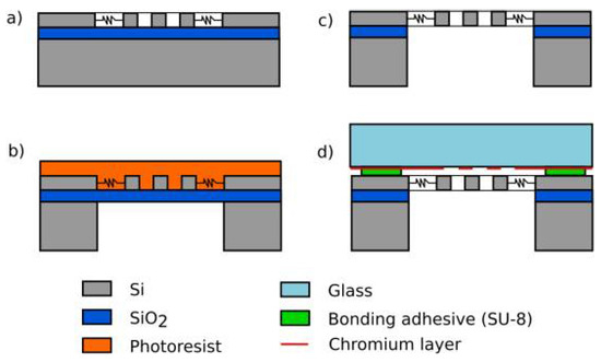
Figure 2.
Fabrication process. (a) Structuring of the device layer. (b) Backside DRIE to remove the substrate beneath the structures. (c) HF etching of the sacrificial SiO2 layer. (d) Bonding of the glass wafer with SU-8.
The mechanical vibration modes of the MEMS structure are determined prior to the measurements by means of finite element method (FEM) simulations. The device’s eigenmodes are simulated with Comsol Multiphysics in a 3D solid mechanics model. Figure 3 depicts the first eigenmodes where the lowest one f1 = 296 Hz is the vibrational mode in x-direction, followed by the basic vibrational mode in z-direction (f2 = 1559 Hz). At f4 = 2496 Hz is the vibrational mode in y- direction. The modes f3, f5, and f6 are torsional modes around the x-, y-, and z-axis, respectively.
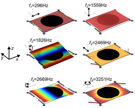
Figure 3.
FEM simulated basic vibration modes of the structure with color coded total deflections.
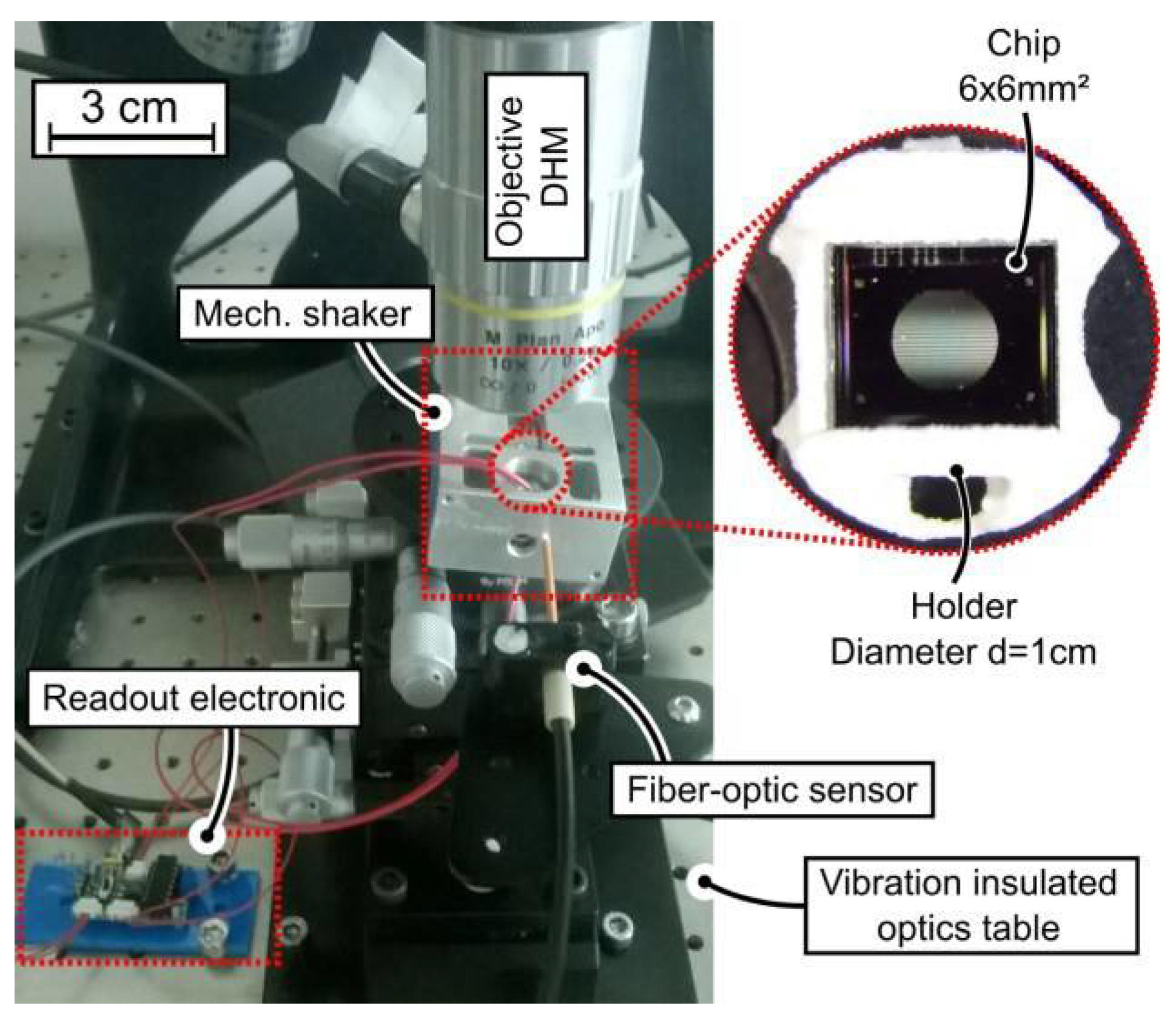
The fabricated MEMS structures are characterized with the help of a digital holographic microscope (DHM; LynceeTec, Lausanne, Switzerland) and a piezo-electric shaker unit. The device is mounted on the shaker with its preferred displacement direction facing in the x-direction. A frequency sweep between 100 Hz and 5 kHz is carried out by applying a sinusoidal voltage at the piezo shaker with an Agilent waveform generator (Agilent, 33220A). The digital holographic microscope is used to quantify the excitation amplitudes of the seismic mass, while a fiber-optic sensor (Philtec D6, Maryland, USA.) is used to measure the input excitation amplitudes, applied by the shaker unit. The measurement procedure is repeated with the device’s preferred displacement direction facing y- and z-direction regarding the shaker’s primary excitation direction. In this way, the basic vibration modes of the structure in x-, y-, and z- direction and the transfer characteristic of the seismic mass for different input excitation directions is calculated. Afterwards, the response of the optical readout out is characterized. An LED and a photodetector are put on the top and bottom side of the MEMS structure, respectively. The resulting photocurrent is converted and pre-amplified by a transimpedance amplifier. Again, a frequency sweep was carried out and the corresponding signals from the readout circuit are measured with a lock-in amplifier (Stanford Research, SR830) (Figure 4). With the recorded signals, the transfer characteristic and sensitivities of the optomechanical transducer were calculated.

Figure 4.
A piezo-electric shaker is used to introduce excitations in different spatial directions at a set of frequencies. The deflections of the mass and the applied excitation amplitudes are evaluated with a digital holographic microscope and a fiber-optic sensor, respectively. The output from the readout circuit is recorded with a lock-in amplifier.
3. Results
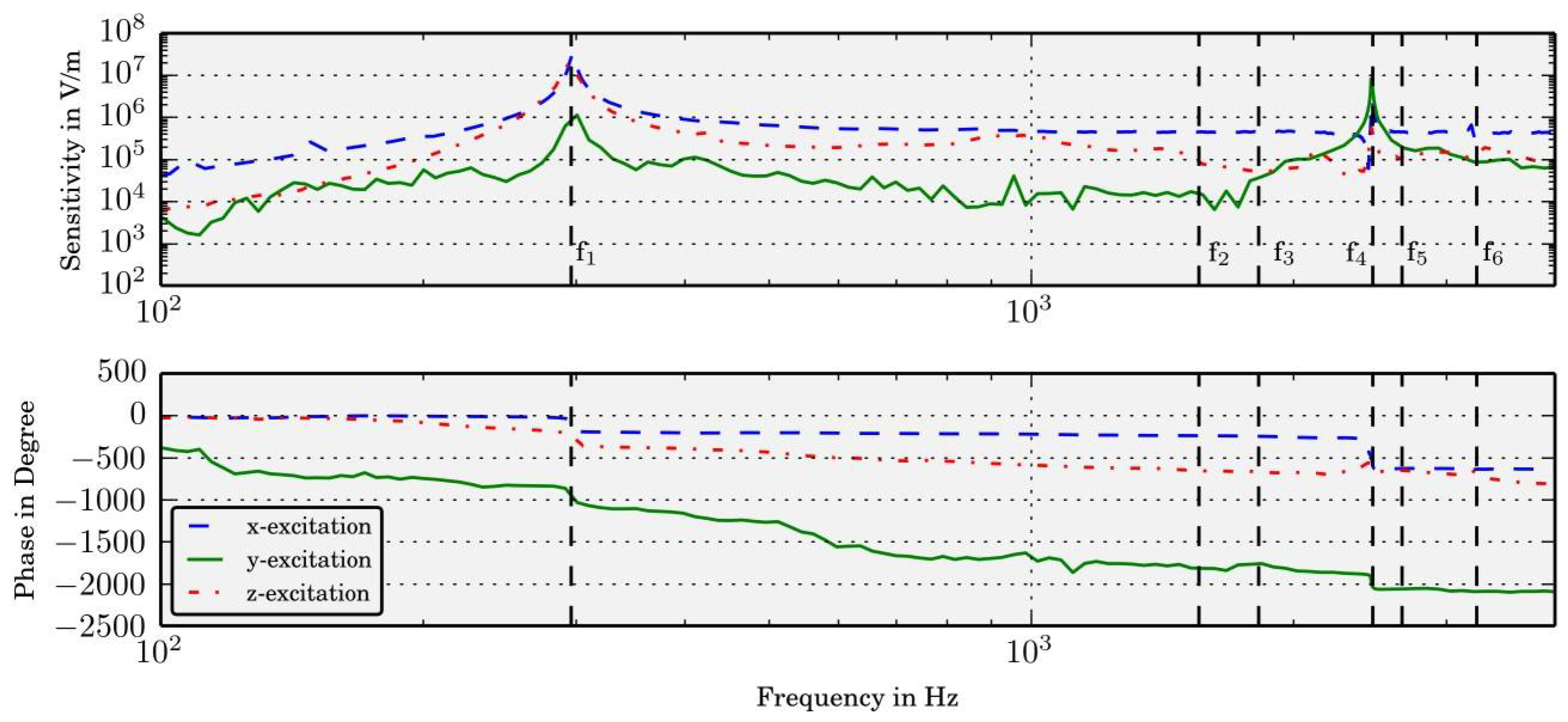
The device was excited at a set of frequencies to obtain the transfer characteristic for input excitations in x-, y-, and z-direction, respectively. The simulated resonance frequencies of the seismic mass match the measured results very well. The response of the optomechanical transducer is depicted in Figure 5. The in-plane vibration modes f1 (x-direction), f4 (y-direction) can be clearly observed both in the amplitude and phase signal of the readout. The out-of-plane modes f2 (z-direction), f3 and f5 (out-of-plane rotational modes) of the seismic mass were observable with the DHM, but not in the output of the optomechanical transducer. Also the in-plane-rotational mode f6 could not be observed.
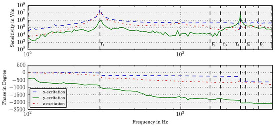
Figure 5.
The transfer characteristic of the optomechanical transducer reveals that the in-plane vibration modes (f1, f4, f6) are in very good agreement with the simulated ones. No out-of-plane modes (f2, f3, f5) are observable in the transducer’s output signals. This indicates that the readout has a negligible cross-sensitivity regarding such out-of-plane deflections.
4. Conclusions
A micromechanical optomechanical transducer was characterized regarding its response to multidirectional input excitations based on the example of a vibration sensor. While the basic vibration modes of the seismic mass could be observed with a digital holographic microscope, the optomechanical transducer is only sensitive to in-plane excitations of the mass in x- and y-directions.
The basic vibration modes in x- and y-directions can be observed for all three input directions. This effect results from a non-ideal positioning of the device on the mechanical shaker and, hence, an at least partly transfer of the input excitation power into the x- and y-vibrational mode. Nevertheless, we have experimentally proven that the sensitivities of the chosen device and aperture design is 3.3×10⁷ V/m in x-direction, 8.23×10⁶ V/m in y-direction, and negligible in z-direction. This information is of use for the future development of tailor-made innovative optomechanical MEMS sensors.
Author Contributions
All Authors contributed equally to the work.
Acknowledgments
This work was supported by the country of Lower Austria, the European Regional Development Fund (ERDF) and the Austrian Science Fund (FWF project number P 28404NBL).
Conflicts of Interest
The authors declare no conflict of interest. The founding sponsors had no role in the design of the study; in the collection, analyses, or interpretation of data; in the writing of the manuscript, and in the decision to publish the results.
References
- Perlmutter, M.; Robin, L. High-performance, low cost inertial MEMS: A market in motion! In Proceedings of the 2012 IEEE/ION Position, Location and Navigation Symposium, Myrtle Beach, SC, USA, 23–26 April 2012; 225–229; pp. 225–229. [Google Scholar] [CrossRef]
- Lammel, G. The future of MEMS sensors in our connected world. In Proceedings of the 2015 28th IEEE International Conference on Micro Electro Mechanical Systems (MEMS), Estoril, Portugal, 18–22 January 2015; pp. 61–64. [Google Scholar] [CrossRef]
- Masako, T. An industrial and applied review of new MEMS devices features. Microelectron. Eng. 2007, 84, 1341–1344. [Google Scholar] [CrossRef]
- Eswaran, P.; Malarvizhi, S. MEMS capacitive pressure sensors: a review on recent development and prospective. Int. J. Eng. Technol. 2013, 5, 2734–2746. [Google Scholar]
- Hortschitz, W.; Kainz, A.; Steiner, H.; Stifter, M.; Kohl, F.; Schalko, J.; Sauter, T.; Keplinger, F. MOEMS Vibration Sensor for Advanced Low-frequency Applications with pm Resolution. Procedia Eng. 2014, 87, 835–838. [Google Scholar] [CrossRef]
- Middlemiss, R.P.; Samarelli, A.; Paul, D.J.; Hough, J.; Rowan, S.; Hammond, G.D. Measurement of the Earth tides with a MEMS gravimeter. Nature 2016, 531, 614–617. [Google Scholar] [CrossRef] [PubMed]
- Kainz, A.; Steiner, H.; Schalko, J.; Jachimowicz, A.; Kohl, F.; Stifter, M.; Beigelbeck, R.; Keplinger, F.; Hortschitz, W. Distortion-free measurement of electric field strength with a MEMS sensor. Nature Electron. 2018, 1, 68–73. [Google Scholar] [CrossRef] [PubMed]


Publisher’s Note: MDPI stays neutral with regard to jurisdictional claims in published maps and institutional affiliations. |
© 2018 by the authors. Licensee MDPI, Basel, Switzerland. This article is an open access article distributed under the terms and conditions of the Creative Commons Attribution (CC BY) license (https://creativecommons.org/licenses/by/4.0/).