Abstract
In this paper, a novel capacitive tactile sensing device has proposed and demonstrated to solve coupling problem within the normal force and shear force by the unique design of electrode shape. In addition, the tactile sensor was added in the measuring capability of torsion sensing compared with traditional capacitive sensor. The perceptive unit of tactile sensor, which was consist of five sensing electrodes to detect three-axial force. The complete tactile sensor composed of a top electrode, a bottom electrode, and a spacer layer. Each capacitive sensing unit comprised a pair of the concentric-shape but different size electrodes (top electrode and bottom electrode). In the future, the proposed tactile sensor can be utilized in the wearable devices, flexible interface, and bionic robotic skins.
1. Introduction
In the past, these sensors were fabricated using silicon and glass substrates, resulting in limitations in the surface. Recently, the flexible tactile sensors have gradually attracted increasing research attention in the artificial skin, touch panels, and control robotic fingers, because of their low cost, bendable, and stretchable characteristics. In general, tactile sensors have been developed maturely in the mechanism, which detected pressure through changes in piezoresistivity, piezoelectricity, and capacitance. Among them, capacitive tactile sensors utilized pair parallel electrodes to perceive force direction and achieve multi-touch ability. In mechanism of capacitive sensing, the applied force upon the tactile sensor resulted capacitance changes in the displacement and overlapped areas among two electrodes of the parallel plate capacitor. The capacitance of a parallel plate capacitor depended on the overlap area of the electrodes A and their separation between two electrodes d, and the capacitance was thus given by: ∆C = ε × A/d, where ∆C, ε, A, and d represent the capacitance, dielectric constant, overlapping area of the electrodes, and distance between the electrodes of the capacitor, respectively. However, previous studies have proposed and demonstrated capacitive tactile sensors to focus on normal force, shear force and pulling force [1,2,3], but few research concentrates on composite force and torsion in capacitive tactile sensor. Actually, the traditional sensing unit that contained four square-shaped capacitors was unable to decouple normal force and shear force when the applied force was not vertical or parallel on the surface. When shear force (x-y plane) involved normal force (z direction), it may cause measurement results inaccurately. Moreover, the traditional approach cannot identify the torsion force which loaded on the tactile sensor. In this study, we have developed the capacitive tactile sensor using concentric- shape electrodes to decouple normal force and shear force and perceive the torsi on force, as shown in Figure 1.
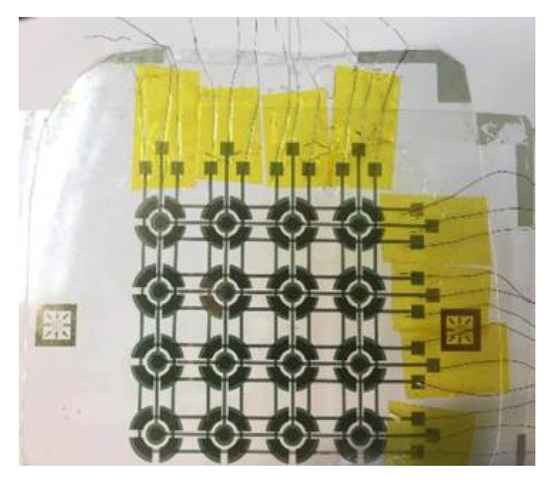
Figure 1.
Schematic of the flexible tactile sensor with concentric-shape electrodes.
2. Fabrication
Regarding to the fabrication of the tactile sensor, polyethylene terephthalate (PET) and polydimethylsiloxane (PDMS) composed principal parts of the structure, including upper layer (PET), top electrode (Au), insulate layer (PDMS), spacer (PDMS), bottom electrode and lower layer (PET) as shown in Figure 2. The 4-inch transparent PET substrates (Toray, T60, 0.188 mm) as the upper and lower layer were cleaned with acetone at room temperature and blow-dried. The PET substrate was span-coated photoresist with 5 µm (AZ4620) onto the surface and patterned the sensor working area by the photolithography. Sputtering Au with 100 nm by RF magnetron sputtering system. and processing lift-off photoresist was regarded as the electrode on PET substrates. Simultaneously, the silicon mold by ICP process was coated with FOTS (1H, 1H, 2H, 2H, Perfluorooctyltrichlorosilane, Alfa Aesar L16606) to prepare the anti-adhesion layer. The PDMS with a base and hardener mixture ratio of 10-1 was poured onto the silicon mold with 3000 RPM. Subsequently, PDMS was solidified in an oven at 100 °C for 1 h to complete the procedure of the insulate layer (0.01 mm) and spacers (0.02 mm). Bonding one of the aforesaid PET substrate (upper layer) on the PDMS surface by UV adhesive was exposed ultraviolet under 100 mV for 3 min, and then the PDMS structure detached from silicon mold. After demolding, the bottom layer was attached on the structure of insulator and spacer between two layers by alignment key and finished a tactile sensor.
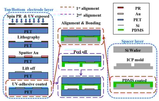
Figure 2.
Schematic of fabrication process in the capacitive tactile sensor.
3. Design Concept of Concentric-Shape Electrode
Inspired by tactile sensor on the robotic finger, the sensing area was 1 × 1 cm2, and the working range of the detected force was limited under 0.5 N in this study. Different from previous study, five capacitors in the bottom and top electrodes were 5 × 5 arranged in one perceptive unit, which composed the proposed tactile sensor. The design concept of electrodes was divided into two parts, one was bottom electrode larger than top electrode, and another part was concentric-shape electrodes. The concentric fan-shape electrodes of each pair were aligned in the radius of the x and y direction (C1–C4), and the concentric circle-shape electrodes were aligned in center of a circle (C5) between two electrodes. The radius of the bottom and top electrodes in one concentric fan-shape were 4.0 mm and 3.5 mm (C1–C4), and the radius of the bottom and top electrodes in one concentric circle-shape were 1.5 mm and 1.0 mm (C5), respectively, as shown in Figure 3a,b. The distance of the clearance between fan-shape capacitor was 1 mm in both x and y directions. Between the bottom and top electrodes, PDMS of 0.02 mm and 0.01 mm was utilized as the spacer and insulator which formed air gap layer in order to increase the capacitive changes easily, as shown in Figure 3c.
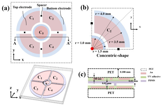
Figure 3.
(a) Top view of the sensing unit which contained five capacitors; (b) Enlarged view of C2 in (a) with dimensions; (c) Cross-sectional of the sensing unit in (a).
4. Measurements and Results
The measurement results as follow: When unloading applied on the tactile sensor, the fan- shaped electrodes (C1–C4) obtained the same initial capacitance (∆C1 = ∆C2 = ∆C3 = ∆C4) and the initial capacitance of the circular electrode was equal to ∆C5. When only the normal force compressed physics space forward -z-direction, the distance among two electrodes decreased and resulted in the capacitance increasing, as shown in Figure 4 (sensitivity: C1, C2, C3 and C4 ≈ 1.558 pF/N, C5 = 0.537 pF/N). When the shear force pushed physics space forward +x-direction, the overlap areas of C1 and C3 decreased (∆C1 and ∆C3: decreased (−), sensitivity: C1 and C3 ≈ −0.833 pF/N); the overlap areas of C2, C4 and C5 were no changes (∆C2, ∆C4, and ∆C5: the initial capacitance), as shown in Figure 5. The C5 electrode is key point that ensure the force was the pure shear force in here, when torsion force applied on the tactile in the x-y plane, the overlap areas of C1, C2, C3, and C4 decreased (∆C1, ∆C2, ∆C3 and ∆C4: decreased (−), sensitivity: C1, C2, C3 and C4 ≈ −0.094 pF/N); the overlap areas of C5 were no changes (∆C5: the initial capacitance), as shown in Figure 6.
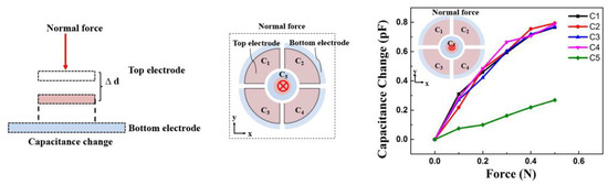
Figure 4.
Schematic of (a) the sensing mechanism in normal force (b) the measured capacitance changes for the normal force in –z-direction.
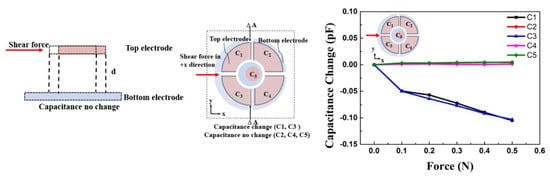
Figure 5.
Schematic of (a) the sensing mechanism in shear force (b) the measured capacitance changes for the shear force in +x-direction.
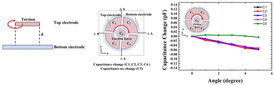
Figure 6.
Schematic of (a) the sensing mechanism in torsion (b) the measured capacitance changes for the torsion in the x-y plane.
5. Conclusions
In summary, a flexible capacitive tactile sensor was constituted with five concentric-shape electrodes, which enable to measure normal force, shear force and torsion. Simultaneously, the demonstrated tactile sensor indeed proved that concentric-shape electrode enabled to avoid unaffectedly the normal force when measured the pure shear force due to concentric-shape electrodes. Furthermore, the fabrication process of the tactile sensor is low cost, without the need of the complex and expensive equipment. In the future, it is anticipated that the flexible tactile sensor can be applied in robotic arms, prosthetic limbs, and wearable devices.
References
- Chuang, S.; Chandra, M.; Chen, R.; Lo, C. Capacitive tactile sensor with asymmetric electrodes for angle- detection-error alleviation. Sens. Actuators A Phys. 2016, 250, 159–169. [Google Scholar] [CrossRef]
- Chandra, M.; Ke, S.; Chen, R.; Lo, C. Vertically stacked capacitive tactile sensor with more than quadrupled spatial resolution enhancement from planar arrangement. Sens. Actuators A Phys. 2017, 263, 386–390. [Google Scholar] [CrossRef]
- Chung, Y.; Chuang, S.; Chen, Y.; Lo, C.; Chen, R. Capacitive tactile sensor for angle detection and its accuracy study. IEEE Sens. J. 2016, 16, 6857–6865. [Google Scholar] [CrossRef]
Publisher’s Note: MDPI stays neutral with regard to jurisdictional claims in published maps and institutional affiliations. |
© 2018 by the authors. Licensee MDPI, Basel, Switzerland. This article is an open access article distributed under the terms and conditions of the Creative Commons Attribution (CC BY) license (https://creativecommons.org/licenses/by/4.0/).