Abstract
This study implements the metal-oxide-semiconductor (MOS) type gas sensor using the TSMC 0.35 μm 2P4M process. The gas concentration is detected based on the resistance change measured by the proposed sensor. This design has three merits: (1) low-cost post-CMOS process using metal/oxide wet etching, (2) composite sensing material based on ZnO-SnO2 coating on the CMOS-MEMS structure, (3) vertical integration of heater and ZnO-SnO2 gas-sensing films using CMOS-MEMS and drop casting technologies. Proposed design significantly increase the sensitivity at the high operating temperature. In summary, the sensitivity of presented sensor increased from 0.04%/% (O2/N2) at near room operating temperature to 0.2%/%(O2/N2) at near 140 °C for the range of 5–50% oxygen concentration.
1. Introduction
The gas sensors can find applications in many fields, such as industrial, automotive, medical and home healthcare, etc. Various approaches, such as electrochemical, metal oxide semiconductor, infrared, catalytic combustion and resonant, have been reported for gas detection. Among these approaches, MOS technology could find extensive applications in medical, transport, HVAC, and consumer. Presently, numerous MOS gas sensors are implemented using the combination of different metal-oxide. However, the MOS type sensing approach has low selectivity. The ZnO [1] and SnO2 [2] exhibit required properties, such as the wide-bandgap semiconductor, to enhance gas sensing performance and sensitivity are two most common sensing materials.
The CMOS-MEMS fabrication technology has the advantages of electrical routing compatibility, monolithic integration of IC and MEMS devices, design flexibility by using multi-stacking thin films, and available foundry service. The CMOS-MEMS has been exploited to realize gas sensors [3,4,5] after adding different sensing materials. Moreover, the multi-layer CMOS process enable the vertical integration of micro heater and gas sensors to reduce the chip size. This study will leverage the CMOS-MEMS process and MOS sensing technologies to implement the gas sensor.
2. Design Concept
The proposed gas sensor is implemented using the standard TSMC CMOS process. Figure 1a illustrates the proposed vertical integration of heater and MOS gas sensor design, and the gas sensor consists of interdigitated electrodes and ZnO-SnO2 sensing film. The proposed CMOS-MEMS gas sensor consists of interdigitated sensing electrodes and vertically integrated heater is 95 × 125 μm2. In addition, the planar dimension of each sensing finger is 10 × 75 μm2.
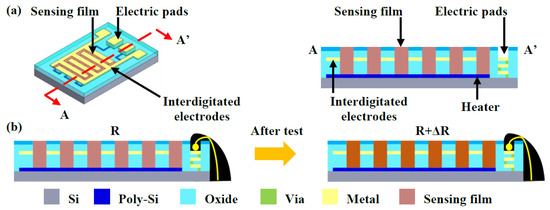
Figure 1.
(a) The design concept of the gas-sensor, and (b) working principle of the gas sensor.
In Figure 1b, the interaction of sensing material and surrounding gases will lead to the variation of electrical conductance for MOS gas sensor. The reaction between the sensing film and O2 gas may result in a significant resistance increase which was detected to determine the presence and concentration of the test gas [6].
3. Fabrication Process and Result
3.1. CMOS-MEMS Devices
By following the design rules, the micro heater, sensing electrodes, and trenches to accommodate sensing materials are defined by standard CMOS layers. Figure 2 shows process flow. Figure 2a shows the chip fabricated by standard TSMC 0.35 μm 2P4M CMOS process. In Figure 2b,c, metal wet-etching and the following oxide wet-etching processes were performed to expose the Al sensing finger. Figure 2d depicts the RIE process to expose bond pads. Figure 2e displays the wire-bonding to PCB board and then sealed/protected by epoxy. Finally, in Figure 2f, the gas-sensing film was dispensed into the gap between sensing fingers and then baked at 60 °C for 30 min. Micrographs in Figure 3a,b show the top-view of typical fabricated devices. Micrographs in Figure 3c,d display sensing finger before and after ZnO-SnO2 dispensing.
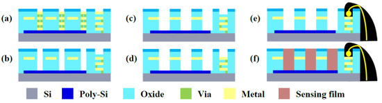
Figure 2.
(a) TSMC 0.35 μm 2P4M process, and (b–f) post-CMOS fabrication processes to implement the proposed gas sensor.
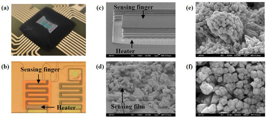
Figure 3.
(a,b) OM micrographs of the sensing chip, (c,d) SEM of the sensing finger before/after ZnO-SnO2 dispensing, and (e,f) SEM of the ZnO-SnO2 thin film.
3.2. ZnO-SnO2 Sensing Film
The sensing film based on ZnO-SnO2 powders was synthesized using hydrothermal synthesis method. The solution was mixed with SnCl4·5H2O, cetyltrimethylammonium bromide (CTAB), NaOH, deionized water, and ethanol in the autoclave at 200 °C for 40 h. Then the synthesis was baked at 60 °C for 6 h to get white powder of SnO2. In order to prepare the sensing complex, the SnO2 was mixed with deionized water and Zn(CH3COO)2·2H2O. After that, the mixture was baked at 60 °C for 6 h to form the ZnO-SnO2. The ZnO-SnO2 was then annealed in quartz furnace at 700 °C for 3 h to get crystalline ZnO-SnO2 microstructures [7]. Figure 3e–f respectively show sensing films (ZnO-SnO2) with different zoom-in magnification, and the high surface-area-to-volume ratio sensing material is demonstrated. Figure 4 shows the EDX spectra analysis of Zno-SnO2. The constituents of Zn, Sn and O are identified by the peaks. Note the additional peaks of C and Pt are caused by carbon conductive-tape and Pt-coating for SEM sample preparation.
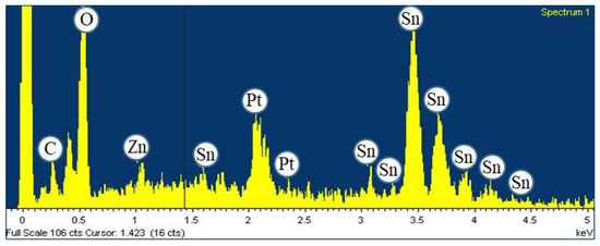
Figure 4.
EDX analysis of ZnO-SnO2.
4. Measurement Setup and Result
Figure 5 displays the measurement setup and results for resistive temperature sensing unit. The chip was heated from 30 to 120 °C with intervals of 5 °C, and the resistance change of the heater is characterized by source meter. Measurement results indicate the non-linearity of heater was 0.01%.
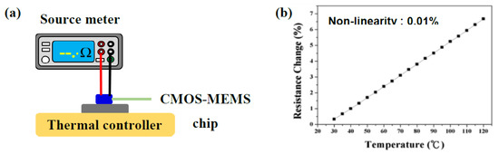
Figure 5.
(a) The test setup, and (b) measurement results, for the resistance change versus temperature.
Figure 6a shows the thermal distribution and temperature measurement setup. To calibrate the emissivity of materials and prevent the influence from environment temperature fluctuation, the thermal controller is specified at 25 °C as a reference. Measurements in Figure 6b show the temperature change/distribution of sensing-chip as input currents varying from 1 to 4 mA. As indicated by the color bars, the temperature is increased for near 100 °C by different input current, and the thermal distribution of the micro heater agrees well with the design. Figure 7a shows the experimental setup to characterize the presented gas sensor. The mass flow controllers (MFC) were used to control gas flow rate and gas mixed concentration. The gas sensor was placed into the test chamber which has purged with N2 to clean out particles and other gases. Then a specific volume of O2 was inject into the mixing chamber to reach a specific gas concentration and then transport to the test chamber. Measurements in Figure 7b depict the responses of O2 concentration at different operating temperature specified by input current of heater. Measurement results show the sensitivity of O2 concentration is improved from 0.04%/% (O2/N2) to 0.2%/% (O2/N2) (within O2 concentration of 5–50%), as input currents increasing from 1 to 4 mA (O2/N2). The results indicate that the sensing responsivity of proposed CMOS-MEMS O2 gas sensor can be improved by the monolithically embedded heater.
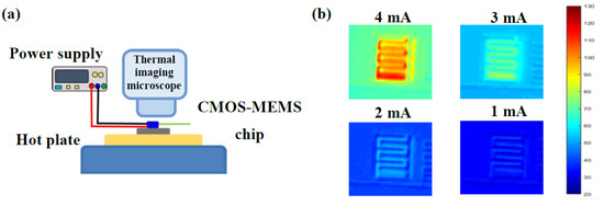
Figure 6.
(a) Experimental setup to characterize the temperature variation of heater, and (b) measurements of the variation of input current with heater temperature.
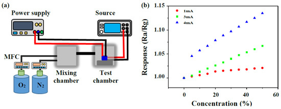
Figure 7.
(a) Experimental setup for gas sensing tests, and (b) responses of the ZnO-SnO2 sensors based on different operation current and oxygen concentration.
5. Conclusions
In this paper, a novel vertical integration integrated COMS-MEMS gas sensor, including MOS type gas sensor filled with ZnO-SnO2 and micro heater detector, is designed and implemented based on the TSMC 0.35 μm 2P4M standard CMOS process. Moreover, the in-house post-processing and hydrothermal synthesis method are required to fabricate the CMOS chip. The sensing structure and filling conditions as well as the morphology of ZnO-SnO2 sensing film were inspected and proven through FE-SEM and EDX. Measurements showed the presented device has high sensitivity (0.2%/%) at operating temperature (approximately 140 °C).
Acknowledgments
This project was support by the ministry of science and technology of Taiwan under grant number MOST 107-2911-I-007-501, MOST 107-2218-E-007-022, MOST 107-2622-8-007-005-TE3, MOST 105-2221-E-007-026-MY3, and MOST 104-2221-E-007-016-MY3. The authors are grateful to the TSMC and the National Chip Implementation Center, Taiwan, for supporting IC manufacturing. The authors are also grateful to D.J. Yao of National Tsing Hua University, Taiwan for providing the measurement facilities.
References
- Alenezi, M.R.; Alzanki, T.H.; Almeshal, A.M.; Alshammari, A.S.; Beliatis, M.J.; Henley, S.J.; Silva, R.P. A model for the impact of the nanostructure size on its gas sensing properties. R. Soc. Chem. 2015, 5, 103195–103202. [Google Scholar] [CrossRef]
- Jin, W.X.; Ma, S.Y.; Tie, Z.Z.; Wei, J.J.; Luo, J.; Jiang, X.H.; Wang, T.T.; Li, W.Q.; Cheng, L.; Ma, Y.Z. One-step synthesis and highly gas-sensing properties of hierarchical Cu-doped SnO2 nanoflowers. Sens. Actuators B Chem. 2015, 213, 171–180. [Google Scholar] [CrossRef]
- Bedair, S.S.; Fedder, G. K, CMOS MEMS Oscillator for Gas Chemical Detection. Available online: https://ieeexplore.ieee.org/document/1426330 (accessed on 11 November 2018).
- Lombardi, A.; Grassi, M.; Malcovati, P.; Capone, S.; Francioso, L.; Siciliano, P.; Baschirotto, A. A CMOS integrated interface circuit for metal-oxide gas sensors. Sens. Actuators B Chem. 2009, 142, 82–89. [Google Scholar] [CrossRef]
- Lee, Y.C.; Cheng, S.W.; Cheng, C.L.; Fang, W. Design and implementation of gas sensor array based on fluorescence quenching detection using CMOS-MEMS process. In Proceedings of the 2017 19th International Conference on Solid-State Sensors, Actuators and Microsystems (TRANSDUCERS), Kaohsiung, Taiwan, 18–22 June 2017; pp. 672–675. [Google Scholar]
- Ding, J.; McAvoy, T.J.; Cavicchi, R.E.; Semancik, S. Surface state trapping models for SnO2-based microhotplate sensor. Sens. Actuators B Chem. 2001, 77, 597–613. [Google Scholar] [CrossRef]
- Chang, H.C.; Hsu, Y.L.; Huang, W.C.; Chen, Y.H.; Chang, I.N. Nanoflower structures of ZnO-SnO2 arranged on nanoporous Al2O3 for sensing ethanol and methanol gases. Microsyst. Technol. 2017, 23, 499–506. [Google Scholar] [CrossRef]
Publisher’s Note: MDPI stays neutral with regard to jurisdictional claims in published maps and institutional affiliations. |
© 2018 by the authors. Licensee MDPI, Basel, Switzerland. This article is an open access article distributed under the terms and conditions of the Creative Commons Attribution (CC BY) license (https://creativecommons.org/licenses/by/4.0/).