1. Introduction
The rise of attention for real-time health monitoring is driving an increasing interest toward highly accurate breathalysers, able to sense low concentration of chemicals in breath to monitor, among the others, diseases [
1] or alcohol concentration [
2]. Each device needs to include one or more flow sensors, to compensate for the different lungs capability and ensure accurate results. Each sensor has an optimal operating temperature of hundreds of degrees, achieved typically with a power dissipation below 10 mW [
3].
The optimal operating temperature depends on the targeted application, with the possibility to detect multiple information by pulsing the signal cycling through different values and post-processing the data [
4]. This approach imposes a thermal cycle on the device, that induces a mechanical stress with a negative impact on the reliability [
5].
The gravity of this problem increases in membrane-type structures [
6], a widely used approach to increase the insulation between active elements and the substrate with a positive effect on power dissipation and sensitivity [
5,
7].
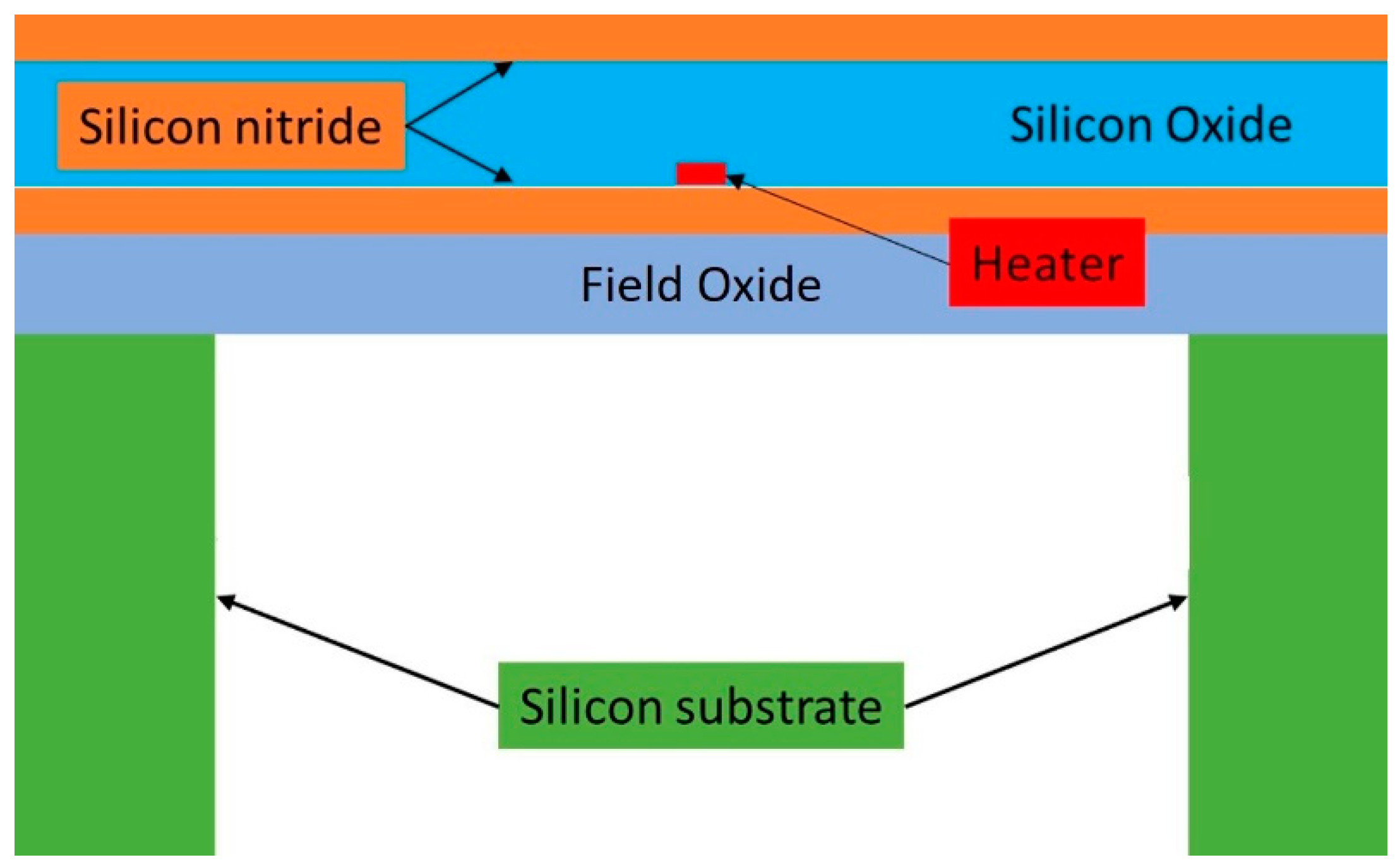
The devices analysed in this work are built with a commercial CMOS process that includes a stack of layers (schematically reported in
Figure 1) with different mechanical properties and thermal expansion coefficients. The fabrication process is finalised with a deep reactive ion etching step, to precisely remove the silicon from underneath the active area creating a closed membrane structure.
This work analyses three thermal flow sensors consisting of a hot wire with different heater and membrane size (at constant ratio), comparing electro-thermal and thermo-mechanical behaviour in order to find the optimum configuration.
The devices are accurately described in
Section 2, while the characterisation processes and their results are reported in
Section 3. Finally,
Section 4 presents the study conclusions, together with the future work.
2. Devices
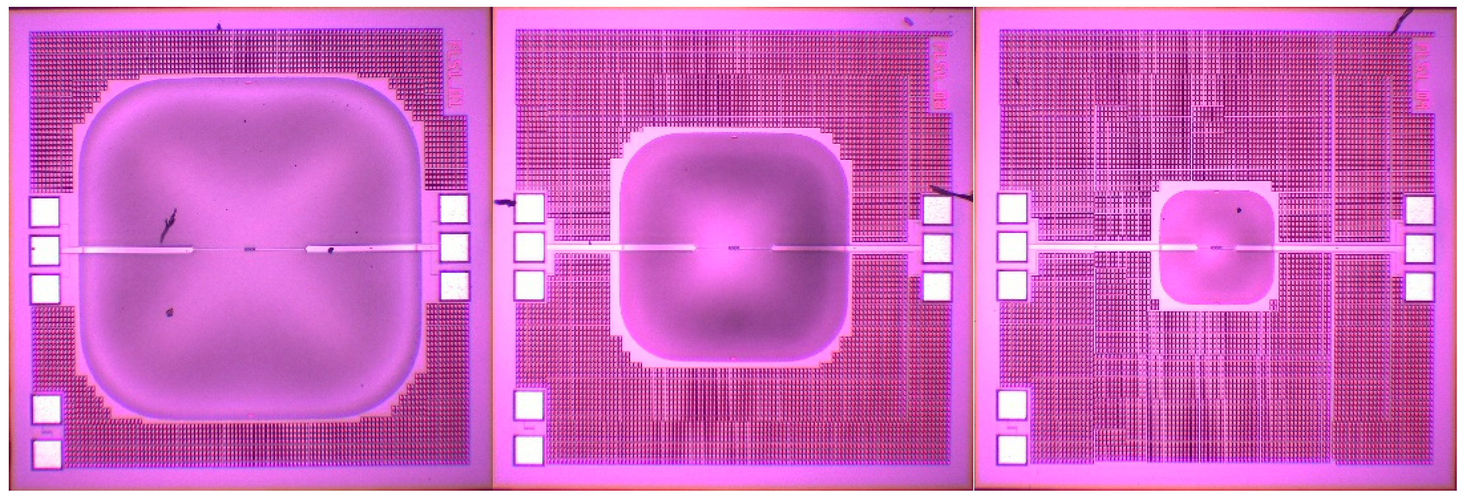
The three devices analysed in this work are flow sensors with different membrane size (1200 µm, 800 µm and 400 µm respectively) including a single hot-wire in the middle (as shown in
Figure 2).
The hot-wire is a thin strip of metal that, when biased with a constant current, generates heat via joule heating, locally increasing the temperature of active area and surrounding fluid.
The metal resistivity strongly depends on the temperature with an empirical quadratic relation (Equation (1)) where T
0 is 25 ◦C and the fitting parameters, provided by the foundry, are reported in
Table 1.
This known relation can be used to extrapolate the device temperature from its resistance. A calibration process then relates the heater temperature with the fluid velocity above the sensor.
3. Results
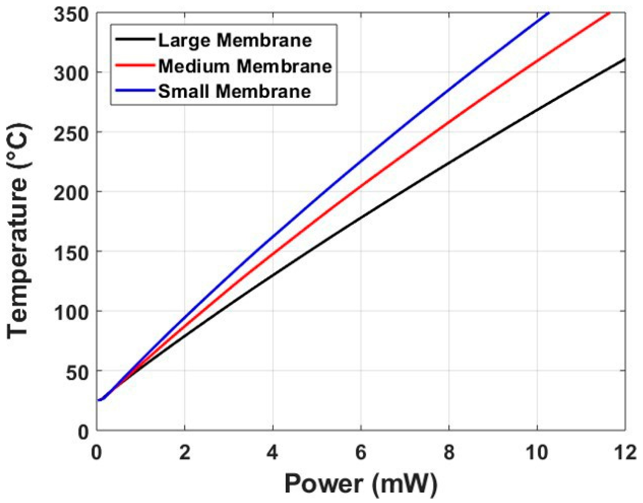
The electro-thermal characterisation used the hot-wire as both heat source and temperature sensor via the change in resistance. To ensure high accuracy in the temperature evaluation, a Kelvin probing approach is used:
two wide tracks are used to deliver the biasing current with a reduced heat generation;
two thin tracks, connected at the edges of the hot wire, are used to accurately measure the voltage across it.
A labview script can be used to convert the current and voltage values in power dissipation and temperature. The results for the three devices are plotted in
Figure 3 below for a wide range of input power.
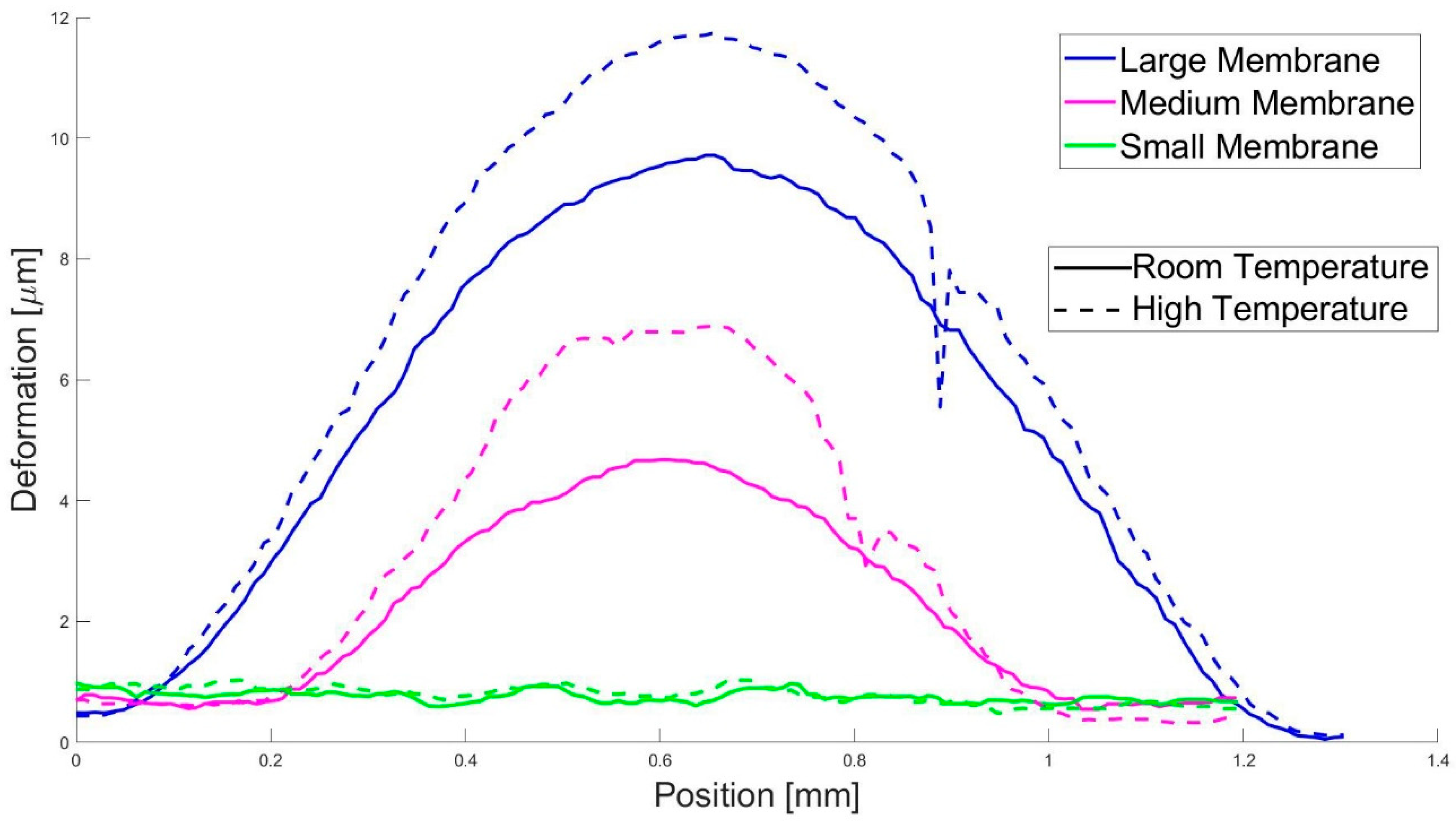
For the thermo-mechanical analysis, the vertical deflection inside the membrane has been recorded in all devices at room temperature and when biased with 10 mA, corresponding to a heater temperature of ≈400, 300 and 200 °C respectively.
Figure 4 shows a comparison between the profiles on a cut perpendicular to the heater passing through the centre of the membrane.
4. Conclusions and Future Work
A complete characterisation of three flow sensors has been performed, looking at the electro-thermal behaviour as well as the mechanical deformation for different membrane size to minimise the internal stress and improve the device reliability.
The findings show that smaller membranes require less power to reach the same operating temperature and, below a threshold membrane size, have a perfectly flat profile, proof of negligible internal stress regardless of the operating temperature.
Future studies are required to evaluate the membrane size effect on the flow response to identify the optimum design.
Author Contributions
Conceptualisation: F.U.; Device design: A.D.L.; Investigation and Data curation: C.F. and E.L.W.G.; Resources and data analysis: N.A. and L.A.F.; Writing-Original Draft: C.F.; Writing-Review & Editing, F.U., A.D.L., E.L.W.G., N.A. and L.A.F.
Funding
This research was funded by Innovate UK grant number 103383.
Conflicts of Interest
The authors declare no conflict of interest. The founding sponsors had no role in the design of the study; in the collection, analyses, or interpretation of data; in the writing of the manuscript, and in the decision to publish the results.
Sample Availability
All the samples used in this analysis are available via Flusso Ltd.
References
- Banach, N.M.; Rust, M.J.; Priefer, R. A portable spectrophotometer-based breathalyser for point-of-care testing of diabetic patients. In Proceedings of the 2013 39th Annual Northeast 39th Annual NEBEC Bioengineering Conference, Syracuse, NY, USA, 5–7 April 2013; pp. 245–246. [Google Scholar]
- Daniel, D.A.; Thangavel, K. Profiling of Artificial Breathalyzer to early diagnosis of Non-communicable Diseases. In Proceedings of the 2015 International Conference on Innovations in Information, Embedded and Communication Systems (ICIIECS), Coimbatore, India, 19–20 March 2015. [Google Scholar]
- De Luca, A.; Falco, C.; Gardner, E.L.; Coull, J.D.; Udrea, F. Diode-based CMOS MEMS thermal flow sensors. In Proceedings of the 19th International Conference on Solid-State Sensors, Actuators and Microsystems (TRANSDUCERS), Kaohsiung, Taiwan, 18–22 June 2017; pp. 2211–2214. [Google Scholar]
- Hepp, C.J.; Krogmann, F.T.; Urban, G.A. Multi-parameter monitoring of binary gas mixtures: Concentration and flow rate by DC excitation of thermal sensor arrays. Sens. Actuators A 2017, 265, 32–39. [Google Scholar] [CrossRef]
- Bhattacharyya, P. Technological journey towards reliable microheater development for MEMS gas sensors: A review. Trans. Device Mater. Rel. 2014, 14, 589–599. [Google Scholar] [CrossRef]
- Laconte, J.; Iker, F.; Jorez, S.; André, N.; Proost, J.; Pardoen, T.; Flandre, D.; Raskin, J.P. Thin Films stress extraction using micromachined structures and wafer curvature measurements. Microelectron. Eng. 2004, 76, 219–226. [Google Scholar] [CrossRef]
- Puigcorbe, J.; Vogel, D.; Michel, B.; Vila, A.; Gracia, I.; Cane, C.; Morante, J.R. Thermal and mechanical analysis of micromachined gas sensors. J. Micromech. Microeng. 2003, 13, 548–556. [Google Scholar] [CrossRef]
| Publisher’s Note: MDPI stays neutral with regard to jurisdictional claims in published maps and institutional affiliations. |
© 2018 by the authors. Licensee MDPI, Basel, Switzerland. This article is an open access article distributed under the terms and conditions of the Creative Commons Attribution (CC BY) license (https://creativecommons.org/licenses/by/4.0/).

 ,
, 


