


Abstract
In this paper, we describe the fabrication of miniaturized flexible Radio frequency RF microcoil for Nuclear Magnetic Resonance (NMR), which have been constructed based on Micro Electro Mechanical Systems (MEMS) technology. 3D Electromagnetic numerical simulations of the physical properties of this microcoil were conducted using Multiphysics software. Numerical simulation shows that the rectangular microantenna (500 × 1000 µm2) on kapton substrate has efficient results in terms of magnetic field, inductance, magnetic energy and resistive losses. This micro-coil is fabricated with three mask levels on polyimide substrate using micromoulding technology.
1. Introduction
In the last decade we have noticed the appearance of electronic polymeric technology, which demonstrated several advantages in terms of low cost, flexibility and enhanced performances in different applications. The choice of these flexible materials as substrates is justified by their interesting intrinsic properties (chemical stability, mechanical, biocompatibility...). These advantages have made it possible to innovate in the field of instrumentation for biomedical applications such as Nuclear Magnetic Resonance (MNR) for imaging or spectroscopy [1,2].
The sensitivity of the NMR signal can be improved by optimizing the signal-to-noise ratio (SNR) of the micro-sensor. In order to increase SNR in NMR application, there are essentially three methods: either by increasing the intensity of the static magnetic field, or by cooling the micro-coils [3] or also by reducing the size of the NMR sensors [4].
In this paper, we describe the fabrication steps of a micrometric radio frequency (RF) micro-coil specially for NMR applications. The use of flexible substrates in this application makes it possible to adapt the micro-sensor to the shape of the studied sample and consequently increase the sensitivity [1,2].
2. COMSOL Simulations
2.1. Design
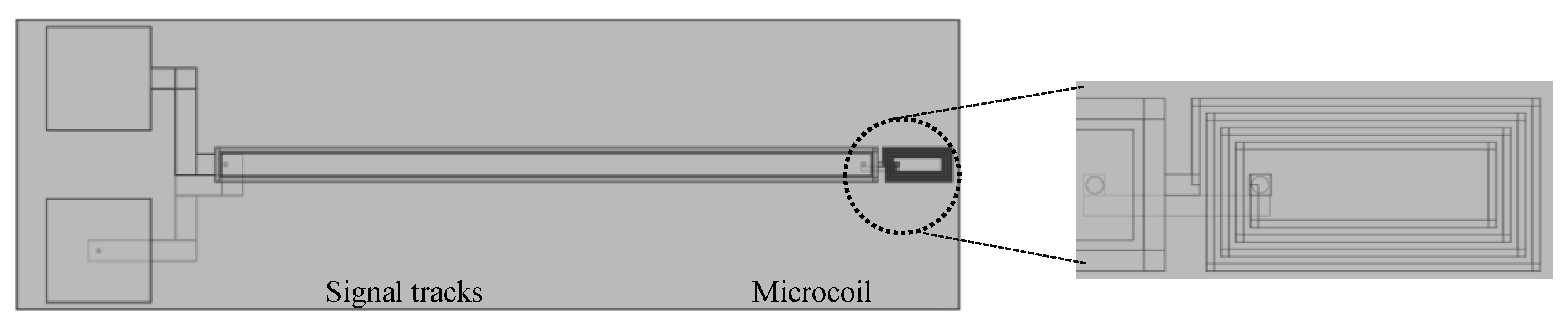
The microcoil investigated in this study was composed of a microcoil connected to signal tracks fabricated on flexible substrates providing low dielectric losses. The microcoil part has a rectangular shape (500 × 1000 µm2): 4, track width: 20 µm, track spacing: 22 µm (Figure 1) [5]. This self-resonates well above the Larmor frequency of interest, i.e., about 300 MHz, and will be tuned and matched capacitively.
Figure 1.
Microcoil design.
2.2. COMSOL Simulation
The micro-coil physical behavior was simulated using the quasi-static approach and solving the Maxwell equations by the finite element method (FEM). This numerical method calculates an approximate solution by projecting on a finite dimension space. The model used [6] for the simulation provides physical parameters of the micro-coil such as the magnetic field for a given excitation, inductance and internal resistance.
The energy of the electric field is mainly concentrated inside the substrate. For this purpose it is essential that the chosen substrate material exhibits low losses in order to avoid the appearance of parasitic capacitances. This property is characterized by a physical magnitude called loss tangent (). As seen in Equation (1), the quality, without load, factor of the resonator increases when this parameter decreases.
For this reason we have chosen to model our micro-coil on tree types of flexible substrates (Kapton, PEEK and PEN). These substrates have a good dissipation factor which helps to improve the quality factor of the micro-coil. The following table (Table 1) summarizes the electrical characteristics of these substrates.
Table 1.
Dielectric characteristics of the polymers substrates.
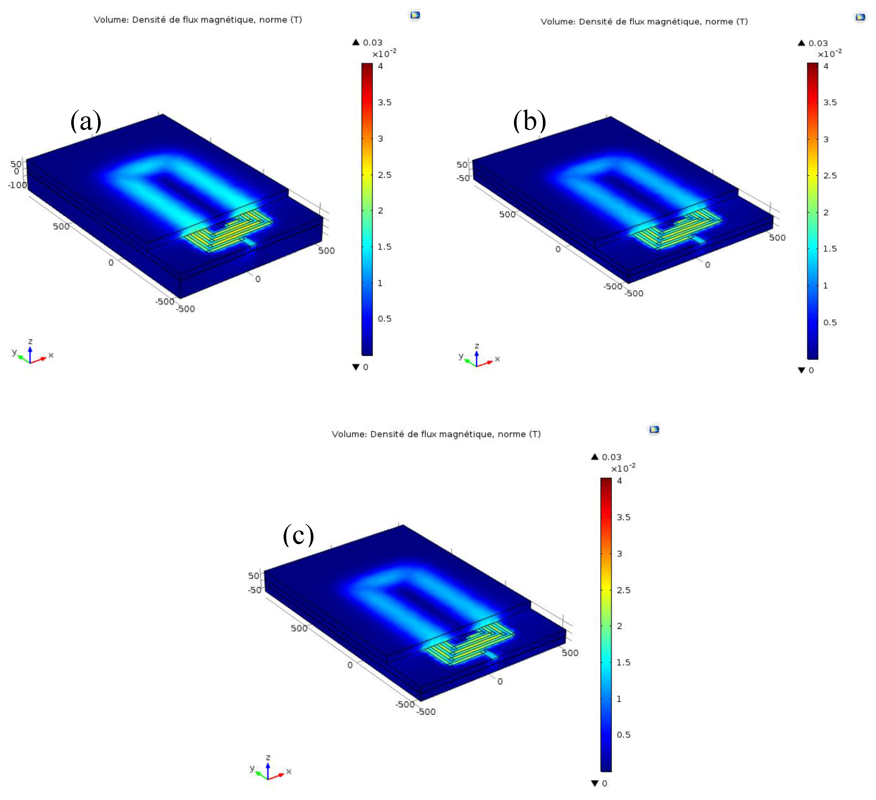
The numerical simulations on Comsol Multiphsics software have shown that the distribution of the magnetic field in the micro-coil is homogeneous in the three substrates (Figure 2). The values of the inductance and the resistance are illustrated in the following table (Table 2). We chose to work with the kapton substrate because it has a good thermal stability and has more chemical resistance (Figure 2).
Figure 2.
Distribution of the magnetic field density for an excitation of 1 A. (a) on a kapton substrate; (b) on a PEEK substrate and (c); on a PEN substrate.
Table 2.
Results of simulations with different substrates using COMSOL.
3. Planar Microcoil Fabrication
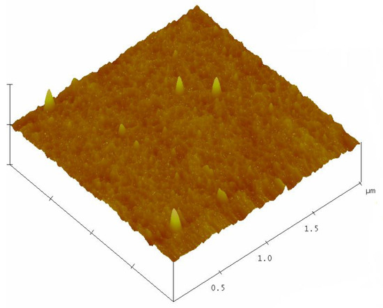
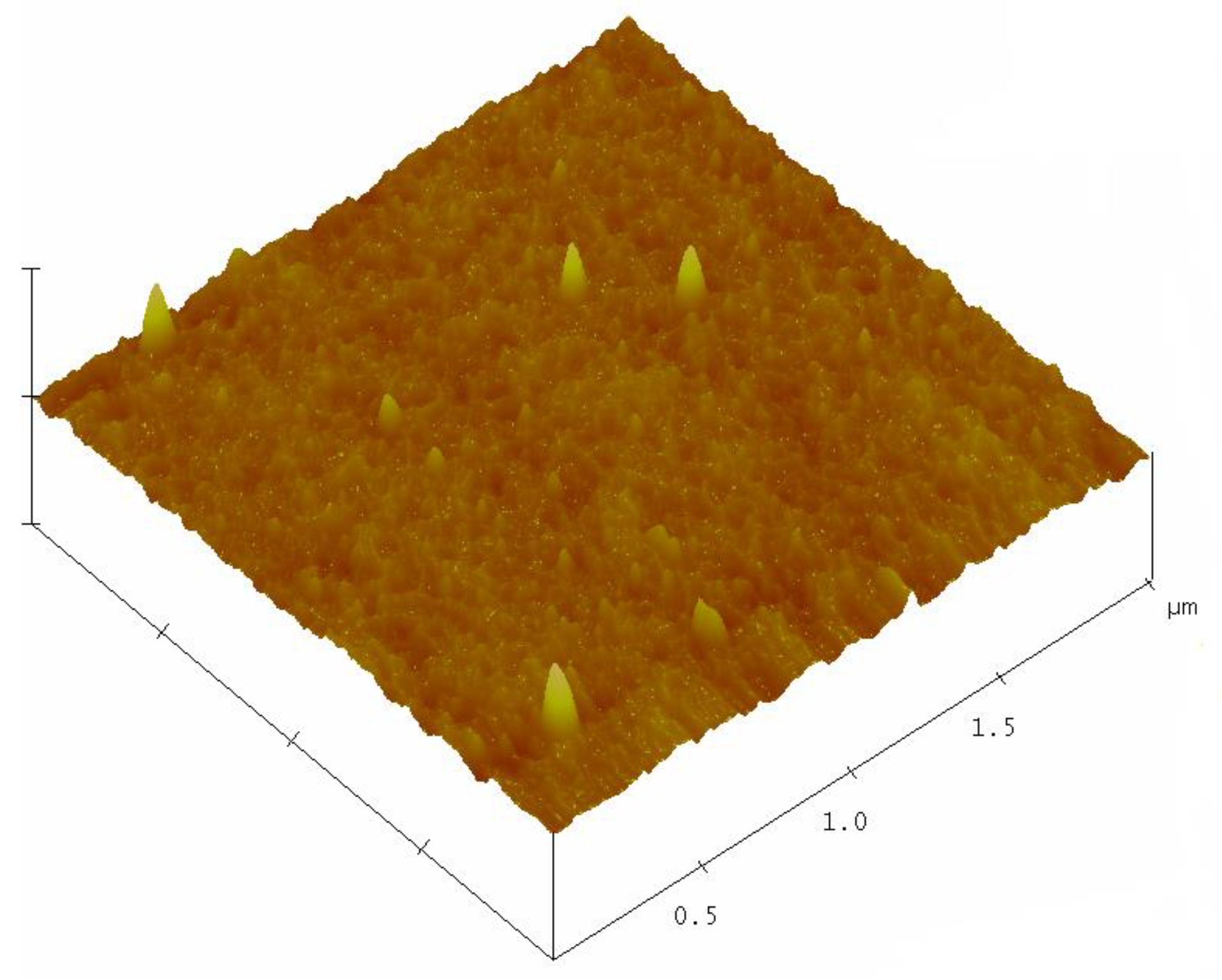
In this section, we describe the fabrication process for the RF microil on Kapton substrate. This polyimide is marketed under the name of Kapton HN, DuPont. We preferred to work with a thickness of 125 μm to facilitate the handling of the substrate during the realization process of the microcoil. The Surface morphology was studied by atomic force microscopy (AFM). It indicated a roughness value about of 1.60 nm (Figure 3)
Figure 3.
Morphology of kapton substrate by atomic force microscopy (AFM).
Fabrication Procss
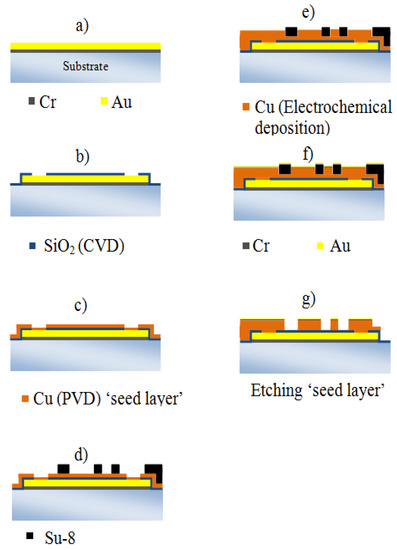
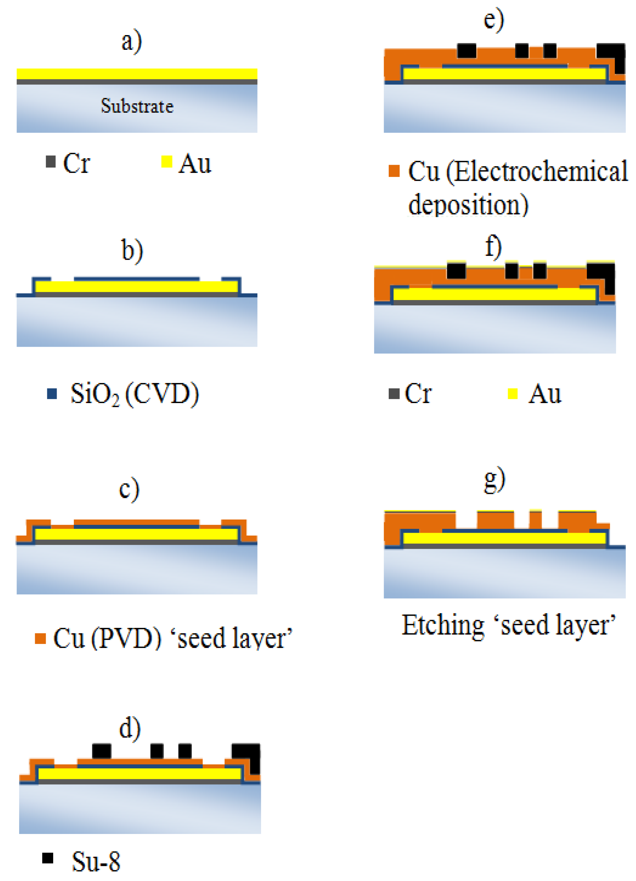
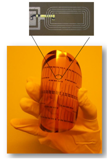
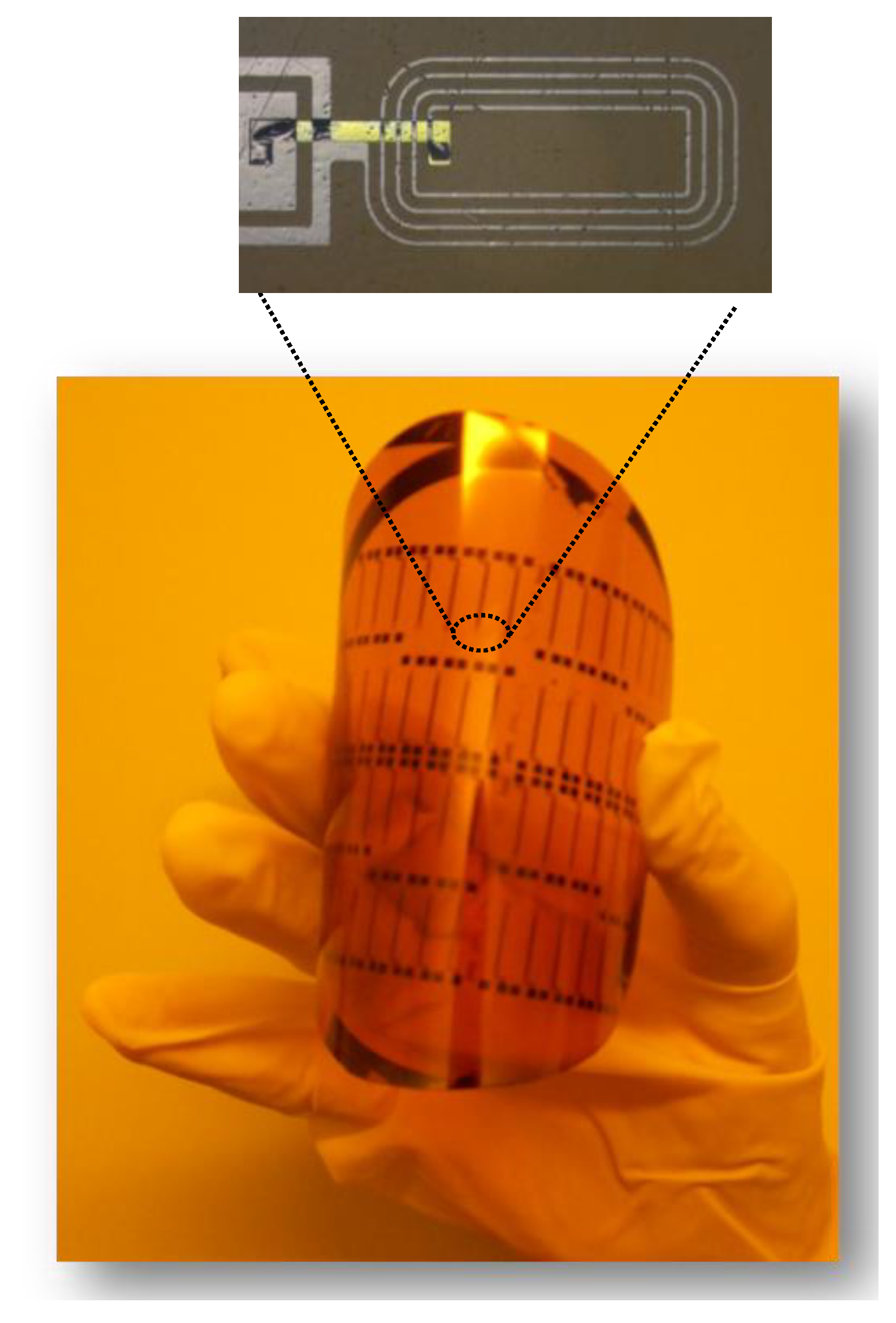
The realization of the microsensor requires three levels of masks. The first level will be used to create underpasses, the second is used to create vias contact and the third allows the microcoil modeling. Before handling, Kapton substrate requires cleaning with acetone bath followed by an another isopropanol bath. We start the process by growing 500 µm of (Cr/Au) using sputtering (Figure 4a). This layer is structured with the first mask to obtain the ‘underpass’. After we cover all the substrate with 600 µm of SiO2 layer deposed by Chemical Vapor Deposition (CVD). Photolithography of this layer allows to take back the contact in underpass (Figure 4b). Next step we deposited 100 µm of copper by sputtering (Figure 4c). We subsequently deposit a thick layer of negative resist type (SU-8 2025). This layer is structured with the third mask in order to construct the mold which will allow the electrodeposition of copper (Figure 4d,e). After, we sputtered a topcoat of (Cr/Au) layer. Finally, we removed the micro-mould and we etched the (Cu) seed layer (Figure 4f,g). Figure 5 shows an example of micro coils on Kapton substrate.
Figure 4.
Fabrication process sequence of the microcoils.
Figure 5.
Microcoils on kapton substrate.
4. Conclusion and Perspectives
During this work, we optimized the choice of the substrate used in the architecture of the micro-coil by 3D modeling under COMSOL software. The three selected flexible substrates (Kapton, PEEK, and PEN) exhibit similar magnetic field distribution and close inductance resistance values. We have also presented a description of the manufacturing process. This will allow us to evaluate the electrical characteristics of the micro-antenna in the next step.
Acknowledgments
This work is supported by the Tunisian Ministry of Higher Education and Scientific Research in the framework of the Tunisian-French cooperation (PHC-UTIQUE) project CMCU2014 “µSESAME” 14G1109.
Conflicts of Interest
The authors declare no conflict of interest.
References
- Couty, M.; Woytasik, M.; Ginefri, J.-C.; Rubin, A.; Martincic, E.; Poirier-Quinot, M.; Darrasse, L.; Boumezbeur, F.; Lethimonnier, F.; Tatoulian, M.; et al. Fabrication and Packaging of Flexible Polymeric Microantennae for in Vivo Magnetic Resonance Imaging. Polymers 2012, 4, 656–673. [Google Scholar] [CrossRef] [Scilit]
- Woytasik, M.; Ginefri, J.-C.; Raynaud, J.-S.; Poirier-Quinot, M.; Dufour-Gergam, E.; Grandchamp, J.-P.; Girard, O.; Robert, P.; Gilles, J.-P.; Martincic, E.; et al. Characterization of flexible RF microcoils dedicated to local MRI. Microsyst. Technol. 2007, 13, 1575–1580. [Google Scholar] [CrossRef] [Scilit]
- Baxan, N.; Rabeson, H.; Pasquet, G.; Châteaux, J.-F.; Briguet, A.; Morin, P.; Graveron-Demilly, D.; Fakri-Bouchet, L. Limit of detection of cerebral metabolites by localized NMR spectroscopy using microcoils. Comptes Rendus Chim. 2008, 11, 448–456. [Google Scholar] [CrossRef] [Scilit]
- Poirier-Quinot, M.; Ginefri, J.-C.; Girard, O.; Robert, P.; Darrasse, L. Performance of a miniature high-temperature superconducting (HTS) surface coil for in vivo microimaging of the mouse in a standard 1.5T clinical whole-body scanner. Magn. Reson. Med. 2008, 60, 917–927. [Google Scholar] [CrossRef] [Scilit] [PubMed]
- Rosillo, J.T. Contribution à l’amélioration de la sensibilité d’un micro-récepteur RMN implantable. Ph.D. Thesis, Université Claude Bernard-Lyon I, Villeurbanne, France, 2014. [Google Scholar]
- Mansour, N.B.; Dridi, C.; Yaakoubi, N.; Fakri-Bouchet, L. Implantable NMR microcoil: Design, Numerical Simulation and Fabrication. In Proceedings of the Madica 2014, Mahdia,Tunisia, 5–7 November 2014. [Google Scholar]
- Professiobal Plasctics. Available online: http://www.professionalplastics.com (accessed on 2 May 2017).
- Dupont. Available online: http://www.dupont.com (accessed on 16 April 2017).
- Available online: http://www.teijindupontfilms.jp/english/product/pen_teo.html (accessed on 16 April 2017).

Publisher’s Note: MDPI stays neutral with regard to jurisdictional claims in published maps and institutional affiliations. |
© 2017 by the authors. Licensee MDPI, Basel, Switzerland. This article is an open access article distributed under the terms and conditions of the Creative Commons Attribution (CC BY) license (https://creativecommons.org/licenses/by/4.0/).