Abstract
This study reports on the integration of a Silicon MEMS hotplate into a natural gas quality analyzer, i.e., a miniaturized gas viscometer used to measure the Wobbe Index (WI). COMSOL Multiphysics simulation was used for selection of the optimum geometry of the hotplate and gas sensing cell. Experimental characterization of the hotplate confirmed its stability under working condition of the sensor. The sensor has been tested by running various gases such as Nitrogen and Methane. The thermal analysis of the sensor and experimental results show a reduced response time of the sensor at lower power consumption and lower thermal time constant.
1. Introduction
As the composition of natural gas varies, the required air to fuel ratio needed to ensure an optimum combustion varies as well. Determining the quality of natural gas provides the ideal fuel to air ratio, which thus allows a safer, a cleaner and a more efficient combustion in natural gas appliances. Wobbe Index (WI) is a quality indicator of combustion gases that allows setting the air to fuel ratio [1]. There is a correlation between the WI and the dynamic viscosity of the gas [2]. Therefore, a natural gas viscometer can be used as a gas quality sensor. The aim of this study is to investigate the performance of a natural gas viscometer integrated with Silicon MEMS hotplate. Figure 1 shows a schematic representation of the sensor. The sensor consists of a gas chamber, a capillary tube, a heating element and a pressure sensor. The working principle of the sensor is based on pumping a gas through the capillary tube by heating it up using the heater, flow of a new gas into the gas chamber by cooling down the gas inside the chamber, measurement of the differential pressure along the capillary during the heating and cooling period, and analyzing the pressure data to determine the gas viscosity [3]. The previous implemented heating element was a Low-Temperature-Co-fired-Ceramic (LTCC) heater made using the screen printing technique. Despite the high accuracy and precision of the results, the sensor operation was overshadowed by many drawbacks of the heater, namely high thermal time constant, high power consumption and the manufacturing of the heater related challenges such as stability, robustness and mass production. MEMS technology offers the possibility to fabricate heaters on a very thin membrane with advantages of thermally isolated heated area from the substrate and reduced power consumption. Therefore, Silicon MEMS hotplates can be a replacement for the LTCC heater of the sensor. This study reports on the design and embedment of a silicon micro-machined Platinum heater in the sensor with the aim of overcoming the aforementioned drawbacks of LTCC heater.
Figure 1.
Schematic of the sensor and its working principle.
2. Design and Simulation
2.1. Design of MEMS Hotplate
Three different micro-hotplates were designed. The devices have substrate dimensions of 5.2 mm × 3.55 mm2, 3 × 3 mm2 and 1.5 × 1.5 mm2, membrane dimensions of 3.2 × 2.55 mm2, 2 × 2 mm2, and 1.0 × 1.0 mm2, and membrane-to-heater ratio (MHR) of 1.4. The larger hotplate was considered to have the same dimensions as the already integrated LTCC heater and the other two were designed in order to study the effect of the hotplate size on the sensor’s performance. The heater shape and geometrical parameters such as width of the heater arms and the interconnections were also chosen by optimizing the temperature distribution using COMSOL Multiphysics simulations as well as considering the electrical characteristic of the sensor. Table 1 summarized the designed parameters of the Silicon hotplates and the actual LTCC heater.
Table 1.
Micro-hotplates design summary.
2.2. Finite Element Modeling of the Sensor
To study the effect of the designed Silicon hotplates on the sensor’s performance, a 3D model of the entire system was built in SolidWorks and were modeled in COMSOL Multiphysics. In the 3D model the capillary tube dimensions were considered to be unique for all the sensors while the sensor’s cavity volume was chosen as the minimum volume that fits the hotplate’s substrate size and fulfills the general requirement for packaging processes. The working gas was assumed to be Nitrogen. A 5 s heat pulse was applied to the heater of the sensor which corresponds to a temperature increase of about 70 °C for the heater. The applied powers are summarized in Table 2. The sensors with hotplate Si_1 consumes 5 times less power than the one with LTCC heater. The reduction in power consumption is even more for smaller Silicon hotplates. The result of the gas differential pressure after switching off the heater is plotted in Figure 2. The time needed for the stabilization of this differential pressure is correlated to the viscosity of the gas and geometrical parameters of the sensor. The measured viscosity values from differential pressure data are summarized in Table 2. The measurement error is less than 8%. As can be seen from the plot the pressure inversion once the heater is switch off in case of a sensor with a Silicon hotplate is sharper. This is due to a faster decrease in the gas temperature resulting from a lower thermal time constant of a Silicon hotplate compare to the one of a LTCC heater, 0.1 s and 1 s, respectively. Lower thermal time constant of the sensor allows having a faster response time as stabilization of differential pressure can be faster.
Table 2.
Summary of Sensors performance, Gas: Nitrogen.
Figure 2.
Simulated differential pressure curve once the heater is off.
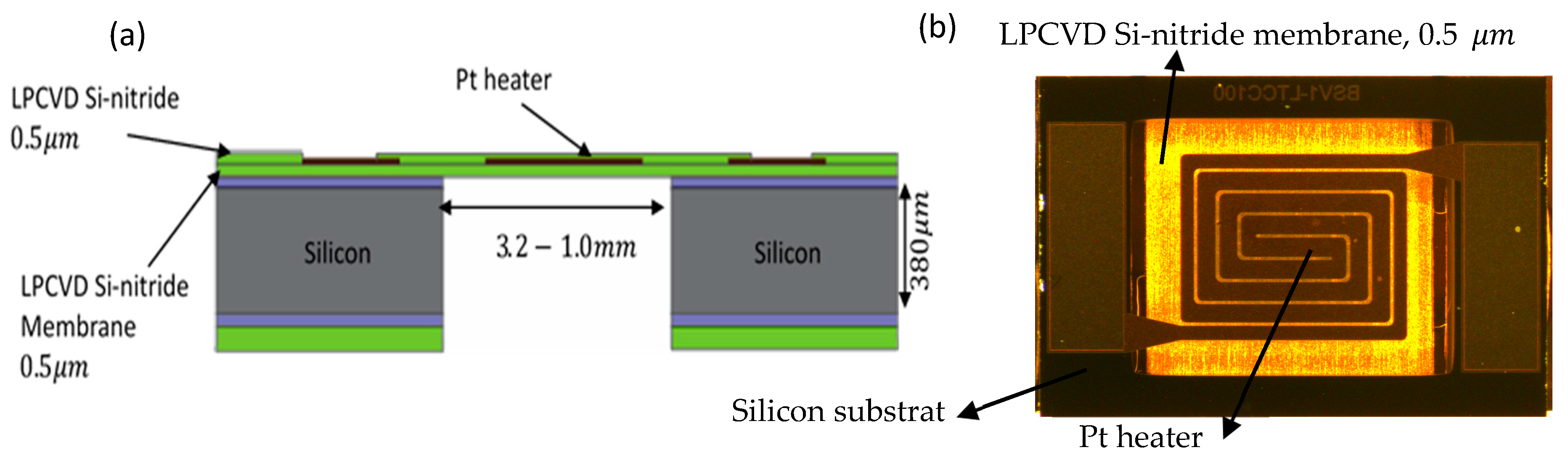
2.3. Fabrication of MEMS Hotplate
The micro hotplates were fabricated on a Silicon substrate and consisted of a Platinum (Pt) heater stacked between two insulators forming a suspended membrane (Figure 3). The membrane thermally isolates the heated area from the silicon chip frame and permits reducing the micro hotplate power consumption. The membrane is released from the backside by dry etching of substrate and wet etching of SiO2.
Figure 3.
(a) Schematic cross-section of various layers comprising a Silicon micro-hotplate; (b) Fabricated micro-hotplate, Si_1-top side view.
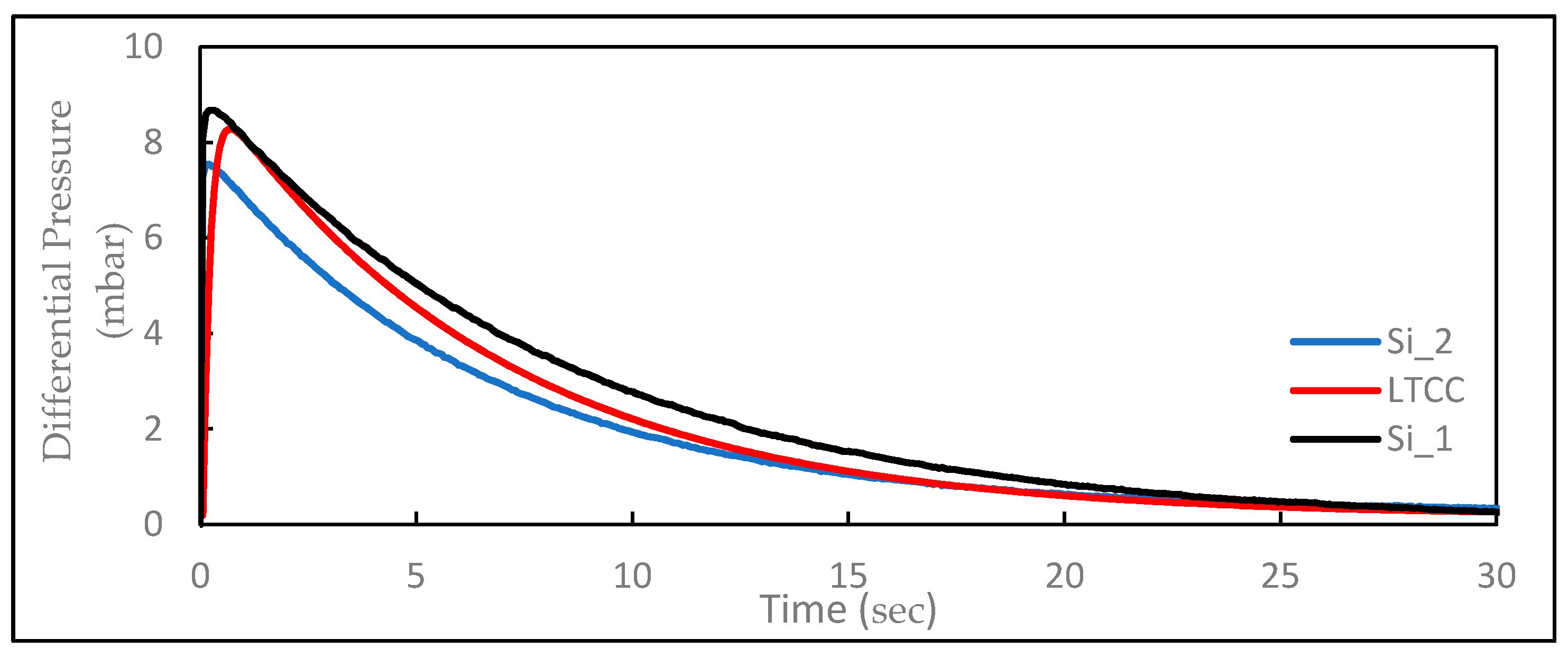
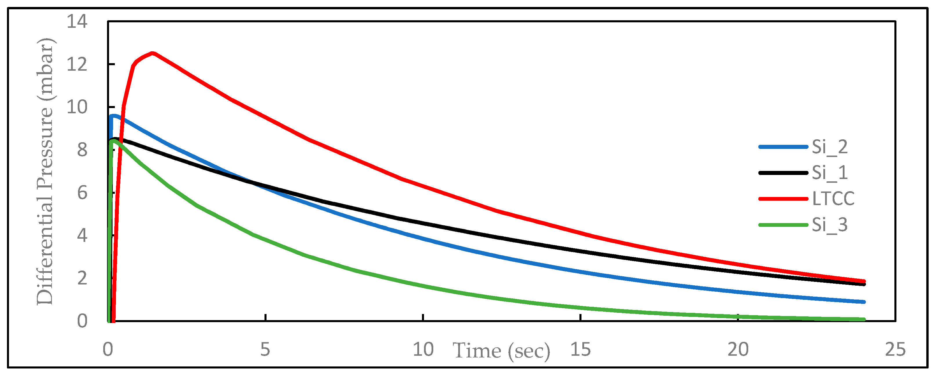
2.4. Characterization of MEMS Hotplate
Electro-thermo-mechanical characterization of the fabricated hotplate, namely analysis of power consumption, temperature distribution, maximum power, and long-term stability, was carried out. Thermal evaluation of the hotplates shows the power consumption by devices Si_1 and Si_2 at an operating temperature condition of 200 °C, are 90 and 103 mW, respectively, and the difference between the average and maximum temperature is about 10 °C. Long-term stability test of the hotplates under a pulse-mode operation condition, a rectangular heat pulse at temperature about 200 °C with frequency of 1 Hz, also showed the heaters exhibited the same resistivity as the beginning of the measurement after about 5 million cycles, corresponding to 15 years operation of the sensor.
3. Experimental Study and Analysis
The sensors with implemented Silicon hotplates were tested by running various mixtures of chemical components of natural gas and their performances were compared with the LTCC sensor. Figure 4 shows the sensors differential pressure data once the heater is switch off. As expected from the simulation data, the differential pressure increases faster in case of sensors with Silicon hotplates. This is because the gas inside the chamber loses the heat faster and consequently a more rapid increase in the differential pressure between two ends of the capillary occurs. A very rapid increase in the differential pressure allows having a faster pressure relaxation and therefore having a lower response time. The applied power and the calculated viscosity are also reported in Table 3. From the experimental results the sensor with a Silicon hotplate can be characterized by a low power consumption (<50 mW) and low response time.
Figure 4.
Experimental differential pressure data once the heater is switch off, Gas: Nitrogen.
Table 3.
Calculated dynamic viscosity by viscometer for Methane and Nitrogen.
4. Conclusions
Silicon MEMS hotplates have the advantages of lower thermal time constant, lower power consumption, and more reliability over LTCC heaters. Confirmed by both experimental and computational studies, the use of Silicon MEMS hotplate as the heating element in the presented gas viscometer makes it an ultra-low power and fast response sensor suitable for mass production.
Acknowledgments
This research was supported by a CTI grant (18610.1 PFEN-NME-F) entitled “AccuWobbe-Accurate, fast response and low power natural gas wobbe analyzer for integration on the natural gas distribution grid and wireless data communication”.
Conflicts of Interest
The authors declare no conflict of interest.
References
- Slim, B.; Levinsky, H.; Knijp, J. Retrofit Wobbe Control System for Industrial Gasburners. In Proceedings of the International Gas Union Research Conference 2017, Rio de Janeiro, Brazil, 24–27 October 2016. [Google Scholar]
- Pickenaecker, K.; Wawrzinek, K.; Trimis, D. Optimization of burners by air-ratio-controlled combustion based on wobbe number measurement. In Proceedings of the European Conference on Small Burner and Heating Technology, Stuttgart, Germany, 16–17 March 2000; pp. 231–240. [Google Scholar]
- Slater, C.; Farine, G. Gas Sensor. European Patent Application EP 2 993 472 A1, 3 September 2016. [Google Scholar]
Publisher’s Note: MDPI stays neutral with regard to jurisdictional claims in published maps and institutional affiliations. |
© 2017 by the authors. Licensee MDPI, Basel, Switzerland. This article is an open access article distributed under the terms and conditions of the Creative Commons Attribution (CC BY) license (https://creativecommons.org/licenses/by/4.0/).