Article

Formation Control of Underactuated AUVs Based on Event-Triggered Communication and Fractional-Order Sliding Mode Control

School of Mechanical and Electrical Engineering, North University of China, Taiyuan 030051, China
*
Author to whom correspondence should be addressed.
Fractal Fract. 2025, 9(12), 755; https://doi.org/10.3390/fractalfract9120755
Submission received: 23 October 2025 / Revised: 10 November 2025 / Accepted: 20 November 2025 / Published: 21 November 2025

Abstract

To address the challenges faced by multiple autonomous underwater vehicles (AUVs) in formation control under complex marine environments—such as model uncertainties, external disturbances, dynamic communication topology variations, and limited communication resources—this paper proposes an integrated control framework that combines robust individual control, distributed cooperative formation, and dynamic event-triggered communication. At the individual control level, a robust control method based on a fractional-order sliding mode observer (FOSMO) and a fractional-order terminal sliding mode controller (FOTSMC) is developed. The observer exploits the memory and broadband characteristics of fractional calculus to achieve high-precision estimation of lumped disturbances, while the controller constructs a non-integer-order sliding surface with an adaptive gain law to guarantee finite-time convergence of tracking errors. At the formation coordination level, a distributed trajectory generation method based on dynamic consensus is proposed to achieve reference trajectory planning and formation maintenance in a cooperative manner. At the communication level, a dynamic-threshold event-triggered mechanism is designed, where the triggering condition is adaptively adjusted according to the state errors, thereby significantly reducing communication load and energy consumption. Theoretically, Lyapunov-based analysis rigorously proves the stability and convergence of the closed-loop system. Numerical simulations confirm that the proposed method outperforms several benchmark algorithms in terms of tracking accuracy and disturbance rejection. Moreover, the integrated framework maintains precise formation under communication topology variations, achieving a communication reduction rate exceeding 65% compared to periodic protocols while preserving coordination accuracy.

1. Introduction

With the continuous development of marine resource exploitation and deep-sea exploration, autonomous underwater vehicles (AUVs) have become indispensable unmanned platforms in modern ocean engineering. Owing to their autonomous control and long-endurance capabilities, AUVs have been widely deployed in tasks such as seabed mapping, pipeline inspection, resource exploration, and ocean environmental monitoring [1,2,3]. In recent years, multi-AUV cooperative formation control has attracted increasing attention. By enabling cooperative operations among multiple agents, multi-AUV systems can significantly enhance mission efficiency, spatial coverage, and system robustness in uncertain and dynamic marine environments. However, due to strong nonlinearities, environmental uncertainties, dynamic communication topologies, and limitations of underwater acoustic bandwidth [4,5,6], achieving accurate formation tracking and coordination remains a challenging problem.
The primary objectives of AUV formation control are precise trajectory tracking and stable formation maintenance. However, the intrinsic characteristics of AUVs—including nonlinear dynamics, strong coupling effects, and underactuation—introduce significant modeling uncertainties such as parameter disturbances, unmodeled dynamics, and external ocean disturbances. These uncertainties severely compromise both control accuracy and system stability. To mitigate these effects, a variety of robust control and disturbance observation strategies have been developed, including PID control [7,8,9], fuzzy control [10,11], sliding mode control (SMC) [12,13,14], neural network compensation [15,16,17], sliding mode observer [18,19,20], extended state observers (ESO) [9,21,22], and nonlinear disturbance observers [12,13], while [14] employed Linear Active Disturbance Rejection Control (LADRC) to observe and provide feedforward compensation for lumped disturbances. Among them, sliding mode control has been extensively applied to underwater systems due to its strong robustness and low dependency on model accuracy; however, the well-known chattering phenomenon limits its control precision. To alleviate this problem, terminal sliding mode control [23,24,25] and high-order sliding mode control [26,27] have been introduced to improve convergence speed while suppressing chattering. Meanwhile, disturbance estimation approaches based on neural networks and observers have demonstrated superior robustness. For instance, adaptive radial basis function neural networks (RBFNNs) have been utilized for real-time disturbance estimation [15,16]; extended state observers have been applied to estimate and compensate for lumped disturbances to enhance tracking accuracy [9,28]; and nonlinear disturbance observers combined with SMC have achieved stronger robustness [12,13]. Furthermore, finite-time and fixed-time disturbance observers [29,30] have improved estimation rapidity and accuracy. Recently, fractional calculus has been introduced into sliding mode control to enrich the controller design space. The fractional operator provides a memory effect that allows smoother transition in both time and frequency domains, effectively suppressing chattering and enhancing disturbance attenuation. Therefore, fractional-order SMC offers potential advantages in terms of robustness, smoothness, and dynamic response [19,20], while fractional-order sliding mode or fuzzy-neural composite controllers [31] enhance system dynamic response and disturbance rejection. Motivated by these findings, this study proposes an integrated fractional-order sliding mode observation–control framework (FOSMO–FOTSMC), which leverages the memory–attenuation characteristics of fractional calculus to smooth high-frequency switching in the frequency domain and accelerate error convergence in the time domain. This framework achieves zero residual disturbance estimation within a prescribed time while effectively mitigating chattering.
In terms of formation control structures, the leader–follower method has been widely adopted due to its simplicity and ease of implementation, where the leader provides global trajectory information and followers adjust their states accordingly [15]. However, single-leader failures may cause formation collapse. To address this, multi-leader, virtual leader, and redundant chain strategies [32,33] have been introduced, improving robustness at the cost of increased communication complexity. The Virtual Structure method treats the formation as a rigid body to achieve high precision [34], but its rigid assumption limits shape flexibility. To improve adaptability, a “virtual path + parameter consensus” mechanism was proposed [19,35], allowing each AUV to follow an individual trajectory while coordinating parameters, though it remains dependent on pre-defined global paths, compromising full decentralization. Alternatively, consensus-based approaches, founded on graph theory, achieve distributed coordination through local information exchange [22,36,37,38], offering good scalability but potentially suffering from oscillations under time delays, packet loss, or topology variations. The behavior-based method [39,40] employs rule-based individual behaviors (e.g., target seeking, collision avoidance) to achieve group coordination but lacks global stability guarantees. On the other hand, considering the limited bandwidth and energy-sensitive engineering constraints of underwater acoustic communication, traditional periodic communication strategies often result in redundant communication and energy waste. Consequently, event-triggered communication (ETC) has gradually emerged as a frontier in distributed control research [16,29,41]. This mechanism significantly reduces communication load by exchanging information only when trigger conditions are met. Related research includes intelligent control based on the dynamic event-triggered mechanism (DETM) [17], which utilizes the DETM to optimize communication resource allocation. Combined with finite-time sliding mode Zeno-resistant communication strategies [25] and energy-optimization methods based on fixed-time convergence [29,41], these approaches achieve a favorable balance between performance and communication efficiency.
Inspired by these works, this paper proposes a hierarchical consensus-based formation control framework integrating dynamic event-triggered communication. The framework adopts a “upper-layer consensus-lower-layer tracking” decoupled design: the upper layer employs a distributed consensus protocol to generate reference trajectories under local communication topology, while the lower layer utilizes the FOSMO-FOTSMC structure for precise tracking and robust disturbance rejection. Furthermore, an adaptive dynamic-threshold event-triggered strategy is introduced to regulate communication frequency according to real-time state errors, achieving a “dense-near, sparse-far” communication policy that optimizes both energy consumption and stability.
The main contributions of this paper are given by the following:
(1) Fractional-order sliding mode observation–control integrated design: An integrated fractional-order sliding mode control method (FOSMO-FOTSMC) is proposed, which utilizes the memory properties of fractional-order calculus to achieve precise estimation and compensation of lumped disturbances. This approach enhances the trajectory tracking accuracy and disturbance rejection capability of AUVs in uncertain environments, providing a solid foundation for reliable formation control.
(2) Hierarchical consensus-based coordination architecture: A distributed control structure with “upper-layer coordination and lower-layer tracking” is designed. The upper layer generates reference trajectories based on consensus protocols, while the lower layer performs precise tracking and compensation. This decouples cooperative control tasks from tracking, enhancing the system’s fault tolerance against individual failures and improving the formation system’s scalability and flexibility in reconfiguring formations.
(3) Dynamic event-triggered communication mechanism: An adaptive dynamic threshold triggering strategy is proposed, adjusting trigger conditions based on real-time errors. This approach effectively reduces communication load and energy consumption while ensuring formation stability.
(4) Stability and performance validation: The stability and convergence of the proposed control strategy are rigorously proven using the Lyapunov stability theory. Simulations validate its superior performance in robustness, formation maintenance, and communication energy efficiency.
It is worth emphasizing the key distinctions between this work and our prior research [19]. Reference [19] focused on a path-following formation problem, where the coordination was achieved through consensus on a single path parameter. In contrast, this paper addresses a more general trajectory-tracking formation problem. We develop a novel distributed virtual trajectory generator, which, combined with a dynamic event-triggered communication mechanism, forms a hierarchical control architecture. This new architecture not only enhances system robustness against dynamic topology changes but also significantly improves communication efficiency. The remainder of this paper is organized as follows: Section 2 introduces the necessary preliminaries and problem formulation. Section 3 presents the design of the proposed AUV observer–controller framework and provides stability analysis. Section 4 details the hierarchical formation control architecture, including the consensus-based trajectory generation method, dynamic event-triggered communication strategy, and theoretical proofs. Section 5 presents numerical simulations and discusses the results. Finally, Section 6 concludes the paper and outlines future research directions.

2. Prerequisite Knowledge and Problem

2.1. Prerequisite Knowledge

2.1.1. Graph Theory

In multi-agent systems (MASs), the communication topology is typically modeled using either directed or undirected graphs. In this paper, the communication topology among follower AUVs is represented by an undirected graph G = V , ε , A , where V = { 1 , 2 , , N } denotes the set of nodes (AUVs), and ε V × V represents the set of edges, corresponding to the communication links between any two nodes. The matrix A = [ a i j ] N × N denotes the adjacency matrix of the graph, which is symmetric. Specifically, if there exists a communication link between nodes i and j , then a i j = a j i = 1 ; otherwise, a i j = 0 . The set N i = { j V : ( i , j ) ε } represents the neighbor set of node i , and its cardinality N i denotes the number of neighbors of node i . The degree matrix of the graph is defined as a diagonal matrix D = diag d 11 , d 22 , , d N N N × N , where each diagonal element is given by d i i = j N i a i j . The Laplacian matrix of the undirected graph G is defined as L = D A = [ l i j ] N × N , where the elements of L are defined as follows:
l i j = d i i ,   i = j a i j ,   i j
Lemma 1
([6]). Consider a connected undirected graph  G  and the Laplacian matrix of  G  is defined as  L . Then the following hold.
1.   L  is positive semi-definite. Specifically, for every  x N , x T L x = i , j ε x i x j 2 0 .
2. The smallest eigenvalue of  L  is  λ 1 = 0 . Its geometric multiplicity is exactly one, which is equivalent to the graph  G  being connected. The second-smallest eigenvalue  λ 2  is strictly positive. Consequently, for every  x N  orthogonal to  1 _ N T x = 0 , the inequality  x T L x λ 2 x 2  holds, and  λ 2  quantifies the algebraic connectivity of  G .

2.1.2. Finite-Time Stability Theorem

Lemma 2
([25]). Consider a nonlinear system  x ˙ ( t ) = f ( x ( t ) ) ,   x ( 0 ) = x 0 n . If there exists a positive definite Lyapunov function  V x  such that
V ˙ ( x ) c V ( x ) α , c > 0 ,   0 < α < 1
then the system states converge to the origin in finite time, given by
T ( x 0 ) = V ( x 0 ) 1 α c ( 1 α )
that is,  lim t T ( x 0 ) x ( t ) = 0 .

2.1.3. Fixed-Time Stability Theorem

Lemma 3
([16]). If a positive definite Lyapunov function V x is continuous and radially unbounded, and satisfies
V ˙ ( x ) γ 1 V α ( x ) γ 2 V β ( x ) , γ 1 ,   γ 2 > 0 , 0 < α < 1 < β
then the system is globally fixed-time stable. In this case, the convergence time is bounded and independent of the initial conditions and satisfies
T T max : = 1 γ 1 ( 1 α ) + 1 γ 2 ( β 1 )
If for all x t , the following inequality holds:
V ˙ ( x ) γ 1 V α ( x ) γ 2 V β ( x ) + ϑ , ϑ > 0
then the system is practically fixed-time stable, meaning that the system states converge to a small neighborhood of the origin within a finite time, the settling time satisfies
T T max : = 1 γ 1 θ ( 1 α ) + 1 γ 2 θ ( β 1 )
where 0 < θ < 1 is a constant.

2.1.4. Basic Concepts of Fractional-Order Calculus

Fractional-order calculus is a generalization of classical integer-order calculus. The fractional-order integral or derivative of a function can be expressed as follows [42]:
D t m t 0 f t = d m d t m f t                     m > 0 f t                                             m = 0 t 0 t f τ d τ m             m < 0
where t 0 denotes the lower limit of the variable t , n 1 < m n , and m is an integer. When m > 0 , the operator represents a fractional derivative, and when m < 0 , it represents a fractional integral. For brevity, the operator D t m t 0 · is denoted as D m · hereafter.
Common definitions of fractional calculus include the Riemann–Liouville, Caputo, and Grünwald–Letnikov forms. The mathematical expression of the Riemann–Liouville definition is given as follows [43]:
D m f t = 1 G n m d n d t n 0 t f τ t τ 1 + m n d τ
where G m = 0 exp t t m 1 d t denotes the Gamma function.
Lemma 4
(Boundedness of fractional derivatives) [43]. If a signal  f t  and its first-order derivative  f ˙ t  are bounded, that is, there exist positive constants  M f  and  M f ˙  such that  f t M f ,   f ˙ t M f ˙ ,   t , then the fractional derivative of any order  m 0 , 1 of  f t , denoted as  D m f t , is also bounded.

2.2. AUV Mathematical Model

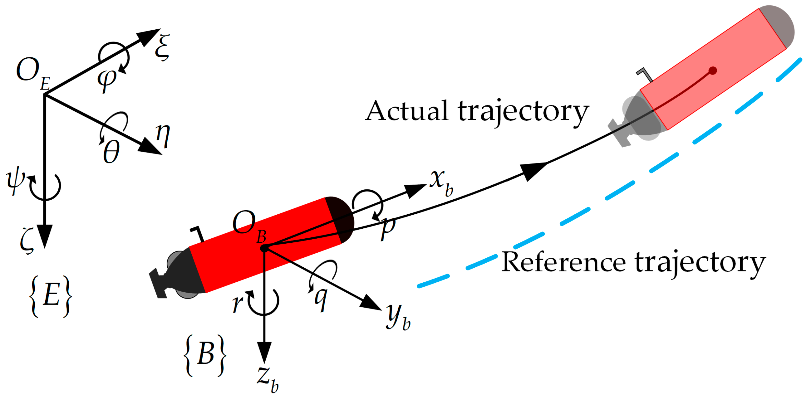
In this section, the three-dimensional (3D) trajectory tracking error model of an underactuated AUV is derived. First, the coordinate frames and relevant notations are defined. Then, the kinematic and dynamic equations of the AUV are presented in detail. Based on these models, the 3D trajectory tracking problem of the AUV is formulated.
As shown in Figure 1, the body-fixed coordinate frame B : O B x b y b z b and the earth-fixed coordinate frame E : O E ξ η ζ are established according to the notation recommended by the International Towing Tank Conference (ITTC). The origin of the body-fixed frame is located at the center of buoyancy. The kinematic and dynamic models of the AUV can be expressed as follows [44]:
η ˙ = J η v M v ˙ + C v v + D v v + g η = τ + τ d
Assumption 1.
The AUV prototype under study has a uniformly distributed mass, and its gravitational and buoyant forces are balanced. To simplify the subsequent controller design, the sway motion dynamics are neglected.
Assumption 2.
Environmental disturbances such as waves and ocean currents have finite energy in practice. Therefore, the disturbance vector τ d and its derivative τ ˙ d are unknown but bounded.
Based on these assumptions, Equation (10) can be described as
x ˙ = u cos ψ cos θ v sin ψ + w cos ψ sin θ y ˙ = u sin ψ cos θ + v cos ψ + w sin ψ sin θ z ˙ = u sin θ + w cos θ θ ˙ = q ψ ˙ = r / cos θ
u ˙ = m 2 m 1 v r m 3 m 1 w q d 1 m 1 u + τ 1 + τ d 1 m 1 v ˙ = m 1 m 2 u r d 2 m 2 v + τ d 2 m 2 w ˙ = m 1 m 3 u q d 3 m 3 w + τ d 3 m 3 q ˙ = m 1 m 3 m 4 u w d 4 m 4 q g 4 m 4 + τ 4 + τ d 4 m 4 r ˙ = m 1 m 2 m 5 u v d 5 m 5 r + τ 5 + τ d 5 m 5
where η = x , y , z , θ , ψ T and v = u , v , w , q , r T denote the position and attitude in the earth-fixed frame and the velocity vector in the body-fixed frame, respectively. The vector τ = τ 1 , 0 , 0 , τ 4 , τ 5 T represents the control input, and τ d = τ d 1 , τ d 2 , τ d 3 , τ d 4 , τ d 5 T denotes the disturbance vector. The matrix J η is the rotation matrix transforming body-fixed velocities into the earth-fixed frame; M is the inertia matrix; C v and D v are the Coriolis–centripetal and hydrodynamic damping matrices, respectively; and g η represents the restoring forces and moments due to gravity and buoyancy.
Let the AUV pose in the earth-fixed frame denote η = x , y , z , θ , ψ T , and the reference trajectory denote η r = x r , y r ,   z r , θ r , ψ r T . The reference attitude angles θ r and ψ r are defined mathematically as
θ r = arctan z ˙ r x ˙ r 2 + y ˙ r 2 ψ r = atan 2 y ˙ r , x ˙ r
The tracking error in the earth-fixed frame is defined as x e , y e , z e , θ e , ψ e T = R η η r T , where R is the rotation matrix from the E to the B . Taking the derivative of the tracking error yields
x ˙ e = r y e q z e + u v p sin θ r sin θ v p cos θ r cos θ cos ψ e y ˙ e = r x e r z e tan θ + v + v p sin ψ e cos θ r z ˙ e = q x e + r y e tan θ + w + v p sin θ r cos θ v p sin θ cos θ r cos ψ e θ ˙ e = q θ ˙ r ψ ˙ e = r / cos θ ψ ˙ r / cos θ r
where v p = x ˙ r 2 + y ˙ r 2 + z ˙ r 2 .
Assumption 3.
The desired reference trajectory η r = x r , y r ,   z r , θ r , ψ r T is known and twice continuously differentiable.

2.3. Control Objectives

Consider a multi-AUV system composed of one leader AUV (indexed by 0) and N follower AUVs (indexed by i = 1, 2, …, N). The overall control objectives of the system are defined in a hierarchical manner.

2.3.1. Upper-Level Consensus Objective (Formation Generation)

Let η 0 t denote the desired pose of the leader, and d i 0 represent the desired relative offset between the i t h follower and the leader. Similarly, d i j denotes the desired relative displacement between followers i and j, determined by the formation geometry. The goal of the upper-level consensus protocol is to generate a set of distributed virtual reference trajectories η r i t such that all followers reach agreement with the leader’s trajectory while maintaining the desired formation. This objective is formulated as
lim t T f η r i t η 0 t + R i 0 d i 0 = 0 , i = 1 , 2 , , N lim t T f η r i t η r j t + d i j = 0 , i , j 1 , 2 , , N
where T f denotes the formation convergence time, and R i 0 is the rotation matrix. d i j = R i 0 d i 0 R j 0 d j 0 .

2.3.2. Lower-Level Tracking Objective (Trajectory Tracking)

Define the local tracking error of the i t h AUV as η i t η r i t . The robust tracking control objective is to ensure that each AUV accurately tracks its own reference trajectory under model uncertainties and unknown environmental disturbances. This objective is formulated as
lim t T t η i t η r i t = 0 , i = 1 , 2 , , N
where T t denotes the tracking convergence time.

2.3.3. Communication Control Objective

Let T t o t a l denote the total simulation time, T s denote the sampling period, and t k i i denote the event-triggered communication instants. Under the above control objectives, an event-triggered communication mechanism is designed to reduce the communication frequency, thereby lowering energy consumption and channel congestion. The communication objective is formulated as
N e t c N p e r γ
where N p e r = T t o t a l T s and N e t c = i = 1 N k i denote the numbers of periodic and event-triggered communications, respectively, and γ represents the communication reduction ratio.

3. Single AUV Tracking Controller Design

The controller design primarily encompasses two core components: First, based on the backstepping method, a Lyapunov function is constructed to design desired velocity commands (including longitudinal velocity, pitch angular velocity, and yaw angular velocity) for pose tracking error. By adjusting relevant parameters, system error convergence is ensured. Second, at the dynamic level, fractional-order operations based on the Riemann–Liouville definition are introduced to construct a fractional-order sliding mode observer. This enables high-precision estimation of lumped disturbances within the system, such as model uncertainties and external disturbances. Building upon this, a terminal sliding surface with fractional-order characteristics is designed, and corresponding force and torque control laws are derived to ensure rapid convergence of velocity tracking errors within finite time.
The overall control system architecture is shown in Figure 2. This approach not only achieves precise trajectory tracking control of the AUV in three-dimensional space but also enhances the system’s adaptability and robustness against unknown environmental disturbances.

3.1. Kinematic Controller Design

Underactuated AUVs lack direct actuation in sway and heave directions. Hence, the 3D trajectory tracking problem can be reformulated as a pose error stabilization problem. The primary objective is to design desired velocity commands. The surge velocity u , pitch rate q , and yaw rate r are selected as the virtual control inputs. The desired velocity command is designed as
U d = u d = k x x e + v p cos θ r cos θ cos ψ e + v p sin θ r sin θ k y y e sign x e ο + x e q d = k θ sin θ e + v p z e cos ψ e + θ ˙ r k z z e sign sin θ e ο + sin θ e r d = k ψ sin ψ e + ψ ˙ r / cos θ r v p y e cos θ r cos θ
where k x , k y , k z , k θ , and k r are positive controller parameters, and o is a small positive constant ensuring non-zero denominators.
Theorem 1.
Considering the error model described by Equation (14), if the desired velocity law is designed as in Equation (18), then the pose tracking error globally and asymptotically converges to zero.
Proof of Theorem 1.
A Lyapunov function is constructed as
V 1 = 1 2 x e 2 + 1 2 y e 2 + 1 2 z e 2 + 1 cos ψ e + 1 cos θ e
Taking the derivative of Equation (19) and substituting Equation (14) into it, we obtain the following:
V ˙ 1 = x e x ˙ e + y e y ˙ e + z e z ˙ e + θ ˙ e sin θ e + ψ ˙ e sin ψ e         = x e u v p sin θ r sin θ v p cos θ r cos θ cos ψ e + v y e + q θ ˙ r + v p z e cos ψ e sin θ e               + z e w + v p sin θ r cos θ 1 cos ψ e + r / cos θ ψ ˙ r / cos θ r + v p y e cos θ r sin ψ e
bringing Equation (18) into Equation (20), we obtain
V ˙ 1 = x e x ˙ e + y e y ˙ e + z e z ˙ e + θ ˙ e sin θ e + ψ ˙ e sin ψ e           = k x x e 2 k θ sin θ e 2 k ψ sin ψ e 2 k y y e x e ο + x e k z z e sin θ e ο + sin θ e + v y e + z e w + v p sin θ r cos θ 1 cos ψ e
Given the properties of the function, we know that v p sin θ r cos θ 1 cos ψ e 2 v p , so w + v p sin θ r cos θ 1 cos ψ e w + 2 v p . When x e 0 and sin θ e 0 , there exist x e ο + x e 1 and sin θ e ο + sin θ e 1 . Therefore, the function V ˙ 1 satisfies the following inequality:
V ˙ 1 k x x e 2 k θ sin θ e 2 k r sin ψ e 2 y e k y v z e k z w + 2 v p
The underactuated AUV has no direct driving forces in the two degrees of freedom of lateral and vertical oscillation, and both velocities v and w are bounded. It is evident that by selecting controller parameters k y > v and k z > w + 2 v p , one can ensure V ˙ 1 < 0 . Therefore, the underactuated AUV navigating at the desired velocity designed by Equation (18) can stabilize the trajectory tracking position and attitude errors. □

3.2. Fractional-Order Sliding Mode Disturbance Observer Design

The AUV dynamics are highly nonlinear and affected by parameter uncertainties and unknown ocean disturbances. To design a robust controller, accurate estimation of lumped disturbances is necessary. Equation (10) can be rewritten as
v ˙ = M 1 τ + H v + Δ
where H v = M 1 C v v + D v v + g η is a known nominal nonlinear function, and Δ = M 1 Δ C v v + Δ D v v + Δ g η τ d represents the lumped disturbance including model uncertainties and time-varying external forces.
The estimated velocity is denoted by v ^ ˙ = M 1 τ + H v ^ + Δ ^ , and the estimation error is v ˜ = v v ^ .
where Δ ^ represents the observed value of the disturbance.
Assumption 4.
Building on Assumption 2, the lumped disturbance Δ comprises bounded unknown dynamics and external disturbances. Moreover, its rate of change is limited by the inertia of the physical process and cannot be arbitrarily fast. Therefore, Δ and its first time-derivative Δ ˙ are assumed bounded, i.e., there exists a positive constant L 1 such that Δ L 1 , Δ ˙ L 1 .
The design objective of the observer is to estimate this lumped disturbance in real time and with high accuracy under the assumption of Assumption 4. Fractional calculus operators possess infinite dimensionality and memory properties in the frequency domain. Incorporating them into the sliding mode observer design can effectively enhance the observer’s dynamic performance, improving both convergence speed and estimation accuracy. Based on the Riemann–Liouville fractional calculus definition, this paper designs a fractional-order sliding mode disturbance observer and its parameter adaptation law in the following form:
Δ ^ ˙ = D m + 1 v ˜ + k v v ˜ ˙ + L ^ sign S + k 1 S α 1 sign S + k 2 S α 2 sign S + k 3 S L ^ ˙ = k 4 S
where 1 < m < 0 , k v , k 1 , k 2 , k 3 , k 4 are positive definite gain matrices, and 0 < α 1 < 1 and 1 < α 2 denote fractional orders.
Remark 1.
To simplify the expression, let L = L 1 + L 2 .
Remark 2.
The inclusion of fractional derivative and integral operators utilizes the memory property of fractional calculus, enabling faster and smoother estimation of Δ .
Remark 3.
Although the adaptive law L ^ ˙ = k 4 S implies that the gain L ^ increases as long as the sliding surface S 0 , this growth does not lead to divergence in practice. Owing to the finite-time convergence property of the proposed fractional-order sliding mode controller and observer, the system states reach a small neighborhood of S = 0 within a fixed time. Once S becomes sufficiently small, the term k 4 S approaches zero, and thus the growth rate of L ^ rapidly decreases. Consequently, L ^ converges to a finite and bounded constant that is large enough to compensate for the lumped disturbance but will not increase indefinitely.
Assumption 5.
Due to the limited thrust of the AUV’s thrusters, rudder effectiveness, and structural strength of the vehicle, the vehicle’s velocity vector v and its derivative must remain bounded over any finite time interval. The observer dynamics (24) are continuous and possess the fixed-time input-to-state stability property [45]. Given that its inputs are bounded, the observed state v ^ and its derivative remain bounded over the same interval. Consequently, the nonlinear function H v ˜ = H v H v ^ and its derivative H v ˜ ˙ are also bounded, i.e., there exists a positive constant L 2 satisfying H v ˜ L 2 and H v ˜ ˙ L 2 hold.
Remark 4.
Given the boundedness of v ˜ by Assumption 5, it follows from Lemma 4 that its fractional-order derivative term D m + 1 v ˜ is also bounded.
Theorem 2.
For the AUV system under Assumptions 2–5, if the FOSMO is designed as in Equation (24) with properly chosen gains k v , k 1 , k 2 , k 3 , k 4 and fractional order m , then both the velocity estimation error and disturbance estimation error converge to a small neighborhood of zero in fixed time.
Proof of Theorem 2.
A fractional sliding surface is designed as
S = k v v ˜ + D m v ˜ ˙ + v ˜ ˙
the convergence law is designed as
S ˙ = k 1 S α 1 sign S k 2 S α 2 sign S k 3 S
A Lyapunov function is designed as
V 2 = 1 2 S 2 + 1 2 k 4 L ˜ 2
Taking the derivative of Equation (27), bringing Equations (24–26) into it yields
V 2 = S S ˙ L ˜ L ^ ˙ k 4 = S k v v ˜ ˙ + D m + 1 v ˜ ˙ + H v ˙ + Δ ˙ H v ^ ˙ Δ ^ ˙ L ˜ S = S H v ˜ ˙ + Δ ˙ L ^ S k 1 S α 1 + 1 k 2 S α 2 + 1 k 3 S 2 L ˜ S S L L ^ S k 1 S α 1 + 1 k 2 S α 2 + 1 k 3 S 2 L ˜ S L S L ^ S L ˜ S k 1 S α 1 + 1 k 2 S α 2 + 1 k 3 S 2 = k 1 S α 1 + 1 k 2 S α 2 + 1 k 3 S 2
According to the fixed-time stability theorem, the observation error Δ ˜ = Δ Δ ^ will converge to an equilibrium point within a fixed time interval. Therefore, the system can provide precise disturbance estimation for the entire control system. □

3.3. Dynamic Controller Design

Based on the disturbance estimate Δ ^ provided by FOSMO, the control objective is to design a control law τ that ensures the AUV’s actual velocity accurately tracks the desired reference in finite time under model uncertainties and disturbances. Define the velocity tracking error as
U e = u e = u u d q e = q q d r e = r r d
The fractional-order terminal sliding surface is designed as
σ = U e + k U D n U e ω sign U e
where k U and ω denote the positive definite gain matrices to be designed, with 0 < ω < 1 and 1 < n < 0 .
Remark 5.
Unlike the integer-order sliding surface, the proposed fractional-order sliding surface introduces a fractional integral term, which embeds a memory characteristic into the control law. This design improves robustness against modeling errors and high-frequency disturbances. The fractional order n 1 , 0 provides an effective balance between fast convergence and smooth control effort.
The sliding mode convergence law is designed as
σ ˙ = K 1 σ β sign σ K 2 σ
where K 1 and K 2 denote the positive definite gain matrices to be designed; β is an adjustable power and satisfies 0 < β < 1 .
Furthermore, the design control law and parameter adaptation law are as follows:
τ = M k U D n + 1 U e ω sign U e L ^ 3 sign σ K 1 σ β sign σ K 2 σ H v Δ ^ + U ˙ d L ^ ˙ 3 = K 3 σ
where K 3 is the positive definite gain matrices.
Remark 6.
The desired velocity is generated by the kinematic controller (19) and is bounded. Meanwhile, according to Assumption 4, the actual AUV velocity is also bounded. Therefore, the velocity tracking error must be bounded. According to Lemma 4, its fractional-order differential term D n + 1 U e ω sign U e is bounded.
Assumption 6.
This assumption is not imposed a priori; it follows directly from Theorem 2. The designed fractional-order sliding mode observer guarantees that the disturbance estimation error Δ ˜ converges to a bounded and closed set within a fixed time. Hence, there exists a positive constant L 3 such that Δ ˜ L 3 . This bound is used to simplify the stability analysis of the controller, and its validity is ensured by the observer itself.
Theorem 3.
Considering the underactuated AUV dynamic system described by Equation (23), under Assumptions 1–6, and employing the fractional-order sliding mode observer (24) for lumped disturbance estimation together with the fractional-order terminal sliding mode dynamic control law in Equation (32), it can be established that the tracking error converges to a neighborhood of the origin in finite time. This implies that the actual velocity of the AUV achieves precise tracking of the desired reference velocity within a finite-time interval.
Proof of Theorem 3.
A Lyapunov function is designed as
V 3 = 1 2 σ 2 + 1 2 K 3 L ˜ 3 2
Taking the derivative of Equation (33), bringing Equations (24) and (32) into it yields
V ˙ 3 = σ U ˙ e + k U D n + 1 U e ω sign U e L ˜ 3 L ^ ˙ 3 / K 3 = σ M 1 τ + H v + Δ U ˙ d + k U D n + 1 U e ω sign U e L ˜ 3 σ = σ Δ Δ ^ K 1 σ β sign σ K 2 σ L ˜ 3 σ L ˜ 3 σ K 1 σ β + 1 K 2 σ 2 L ˜ 3 σ = K 1 σ β + 1 K 2 σ 2
According to the finite-time stability theorem, the sliding-mode variables converge to zero within a finite time, and the velocity tracking error also converges to zero within a finite time. □

4. Formation Controller Design

4.1. Controller Principle

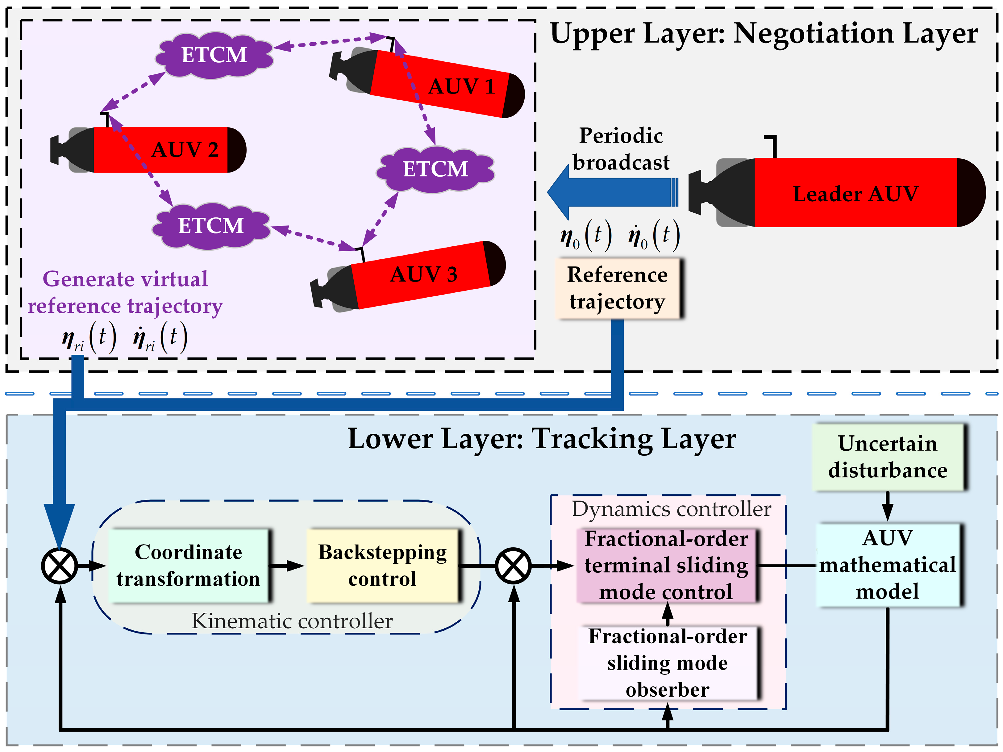
The proposed formation controller adopts a hierarchical “upper-layer consensus—lower-layer tracking” architecture, as illustrated in Figure 3. The core idea is to decouple the leader’s global guidance information from the followers’ local cooperative information. Key data are exchanged on demand via a dynamic event-triggered communication mechanism, effectively reducing redundant communication compared with conventional periodic broadcasting, while the consensus protocol ensures formation accuracy and synchronization.
At the upper consensus layer, the leader AUV periodically broadcasts its state information to all followers. Each follower communicates only with its predefined neighbors when the event-triggering condition is satisfied. Using the locally received neighbor information, each follower generates its virtual reference trajectory through a distributed dynamic consensus algorithm, achieving cooperative trajectory coordination and global synchronization within the formation. This design exhibits strong fault tolerance: if a single AUV fails, its tracking error affects only its own local performance and does not propagate to adjacent agents through the control law. Other AUVs can still negotiate their desired trajectories through local communication, maintaining overall formation integrity. Moreover, formation reconfiguration can be achieved simply by adjusting relative offsets in the upper-layer consensus process without modifying the lower-layer tracking controller, enhancing flexibility and robustness. At the lower tracking layer, each AUV uses its locally generated virtual trajectory as a reference and executes a fractional-order sliding mode observer (FOSMO) combined with a fractional-order terminal sliding mode controller (FOTSMC). This robust control law guarantees finite-time convergence of the AUV’s actual motion to the reference trajectory, thereby achieving high-precision formation control in three-dimensional space.

4.2. Consensus-Based Trajectory Generation

The consensus-based trajectory generation follows a distributed update law that enables coordinated motion among AUVs. Each follower iteratively adjusts its virtual reference trajectory based on relative state discrepancies with its neighbors within the dynamically changing communication topology. The update law is designed as
η ˙ r i t = j N i k i j a i j t η r i t η r j t + d i j k i 0 a i 0 η r i t η 0 t + R i 0 d i 0 + η ˙ 0 t
where η r i t denotes each follower AUV’s reference trajectory, and serves as a virtual reference state used to construct the upper-layer consensus model. η 0 t represents the leader’s desired reference trajectory. N i denotes the communication neighbor set of AUV i. a i j is the element of the adjacency matrix. a i 0 represents the leader’s connectivity weight. d i j denotes the desired relative offset between follower i and follower j as determined by the formation geometry, and d i 0 represents the desired relative offset between follower i and the leader. k i j and k i 0 are tuning coefficients.
This consensus protocol ensures that all followers asymptotically synchronize their virtual trajectories with the leader’s reference, thereby maintaining both geometric formation integrity and motion coordination—even in the presence of switching communication topologies or localized link failures.
Assumption 7.
The communication topology graph G among followers is undirected and connected.

4.3. Dynamic Event-Triggered Communication Mechanism

In multi-AUV formation systems, the event-triggered mechanism (ETM) aims to balance formation consistency and communication efficiency. It minimizes unnecessary underwater acoustic transmissions—thereby reducing energy consumption and channel congestion—while ensuring that state synchronization occurs in time to maintain formation stability. For each follower, define its state error as
e i t = η r i t k i i η r i t , t t k i i , t k i + 1 i
where the variable e i t is introduced to measure the deviation between the current state of an AUV and its last broadcasted state, serving as the core basis for triggering communication. t k i i denotes the most recent triggering instant determined by the triggering law, η r i t k i represents the broadcasted value of AUV i at the last triggering instant t k i , and η r i t is its current actual value
Remark 7.
A larger value of e i t indicates that the AUV’s current state has significantly deviated from its previously broadcasted state. If neighboring AUVs continue to update based on outdated information, their trajectories will diverge.
The threshold setting adopts an adaptive strategy: during the initial stage of system operation, since tracking errors are relatively large, the threshold is relaxed to reduce redundant communications. As the system converges and the tracking error decreases, the threshold is gradually tightened to improve control precision. The dynamic event-triggering law is designed as
t k i i = inf t > t k i 1 i     e i t χ i t χ i t = k χ 0 1 + k χ 1 e i t exp k χ 2 t + k χ 3 χ i t = max χ i t min , min χ i t max , χ i t
where χ i t is the designed dynamic threshold that varies according to changes in state deviation. The terms χ i t min and χ i t max represent the lower and upper bounds of the threshold, respectively. χ i t is confined to the interval χ i t min , χ i t max through saturation to ensure smooth variation, balancing both stability and feasibility. k χ 0 , k χ 1 , and k χ 2 are tuning coefficients. A small constant k χ 3 is introduced and maintained after convergence to prevent χ i t from becoming exactly zero.
Remark 8.
To prevent abrupt jumps in variable χ i t , it is smoothed using the formula χ i t k = α χ i t k 1 + 1 α χ i t k , where χ i t k 1 is the threshold value at the previous instant and α = 0.3 is a tuning coefficient.
The above design exhibits the following characteristics: during the initial phase with large errors, a wider threshold effectively reduces unnecessary event triggers; as the error gradually converges, the threshold automatically shrinks to ensure final control precision and stability. By setting upper and lower bounds on the threshold, the system avoids performance degradation due to overly large or small thresholds. Smooth and continuous variation in the threshold prevents controller oscillations caused by abrupt changes. Furthermore, an exponential decay term is introduced to further enhance the system’s convergence speed.

4.4. Stability of ETM and Lower Bound on Triggering Intervals Analysis

To ensure the practical applicability of the proposed distributed formation control strategy, this section rigorously analyzes the stability of the closed-loop system and the feasibility of the communication mechanism.
Let the consensus deviation variable of follower AUV i (i = 1,2,…,N) be denoted as δ i t = η r i t η 0 t + R i 0 d i 0 , and the control objective is defined as
lim t T f δ i t = 0 , t T f , δ i t = 0
According to the triggering instants determined by the dynamic event-triggered mechanism, the consensus trajectory update rule in Equation (34) can be rewritten as
η ˙ r i t = j N i k i j a i j t δ i t k i δ j t k i k i 0 a i 0 δ i t k i + η ˙ 0 t
where δ i t k i = η r i t k i η 0 t + R i 0 d i 0 denotes the broadcast deviation at triggering instant t k i .
Theorem 4.
Consider the multi-AUV formation system. If the consensus trajectory update rule satisfies Equation (39), then the consensus deviation variable δ i t will converge to zero, indicating that the system is asymptotically stable.
Proof of Theorem 4.
Taking the derivative with respect to δ i t and substituting Equation (39) yields
δ ˙ i t = j N i k i j a i j t δ i t k i δ j t k i k i 0 a i 0 δ i t k i
A Lyapunov function is designed as
V 4 = 1 2 i = 1 N δ i T t δ i t
Taking the derivative of Equation (41), bringing Equation (40) into it yields
V ˙ 4 = i = 1 N δ i T t δ ˙ i t           = i = 1 N δ i T t j N i k i j a i j t δ i t k i δ j t k i i = 1 N δ i T t k i 0 a i 0 δ i t k i           = 1 2 i = 1 N j N i k i j a i j t δ i T t δ i t k i δ j t k i + δ j T t δ j t k i δ i t k i k i 0 a i 0 i = 1 N δ i T t δ i t k i
From Equations (37) and (38), it is known that the error between the broadcast deviation δ i t k i and the current value δ i t at the triggering instant satisfies δ i t k i i δ i t = η r i t k i i η r i t χ min , where χ i t min is the lower bound of the triggering threshold. Thus, using the approximation δ i t k i i δ i t , substituting into Equation (42) gives
V ˙ 4 = i = 1 N 1 2 j N i k i j a i j t δ i T t δ j T t 2 + k i 0 a i 0 δ i T t 2
Define the extended Laplacian matrix L E t = L t + B , where L t is composed of k i j a i j t and B = diag k i j a i 0 is the leader connectivity matrix. Since L t and B are symmetric matrices, L E t is also symmetric and has a minimum eigenvalue λ min t > 0 such that
V ˙ 4 = i = 1 N 1 2 j N i k i j a i j t δ i T t δ j T t 2 + k i 0 a i 0 δ i T t 2 λ min t V 4
Zeno behavior, characterized by excessively frequent event triggers in a short time leading to system failure, must be avoided by proving the existence of a strictly positive lower bound for the triggering interval [41,46].
Theorem 5.
Under the dynamic event-triggered law (36) proposed in this paper, for any AUV i, the time interval between two consecutive triggering instants has a strictly positive lower bound, i.e., no Zeno behavior occurs in the system.
Proof of Theorem 5.
Let t k i i be the k i t h triggering instant of AUV i, and the subsequent triggering instant be t k i + 1 i . The triggering interval is defined as Δ t k i i = t k i + 1 i t k i i . The state error is defined as
e i t = η r i t k i i η r i t = δ i t k i i δ i t
Taking the derivative of Equation (45) yields e ˙ i t = δ ˙ i t . Since δ i t converges, δ ˙ i t has an upper bound. Let δ ˙ i t N and N > 0 , then we obtain e ˙ i t = δ ˙ i t N .
At the triggering instant t k i i , the error is reset, i.e., e i t k i i = 0 . According to the mean value theorem for integrals, for any t t k i i , t k i + 1 i , we obtain
e i t = t k i i t e ˙ i κ d κ t k i i t e ˙ i κ d κ N t t k i i
When t = t k i + 1 i , the triggering condition is satisfied with e i t k i + 1 i = χ i t k i + 1 i . Combining this with χ i t χ i t min as defined in Equation (37), we obtain
N Δ t k i i χ i t min Δ t k i i χ i t min N = Δ t min
Since χ i t min > 0 and N > 0 , it follows that Δ t min > 0 , implying the existence of a strictly positive lower bound for the triggering interval. Therefore, no Zeno behavior occurs in the system. □

4.5. Overall Closed-Loop System Stability

The proposed control framework constitutes a hierarchical closed-loop system. While the preceding theorems have established the stability of individual components, this subsection provides a synthesized stability analysis for the overall integrated system, explicitly considering the interplay between the sliding mode observer, controller, and the time-varying network.
The overall formation error e f , i t = η i t η 0 t + R i 0 d i 0 for follower AUV i can be decomposed into two distinct components:
1.
The consensus error is δ i t = η r i t η 0 t + R i 0 d i 0 , which is governed by the upper-layer dynamics.
2.
The tracking error is Ρ i t = η i t η r i t , which is governed by the lower-layer dynamics.
The stability of the overall system is analyzed as follows:
1. Upper-layer stability with event-triggered communication: As proven in Theorem 4 and Theorem 5, the distributed consensus protocol under the dynamic event-triggered mechanism guarantees that the consensus error δ i t is asymptotically stable, and the system does not exhibit Zeno behavior. Considering bounded perturbations present in practical systems, the consensus error is uniformly ultimately bounded (UUB). A key feature of this mechanism is that the broadcasted reference trajectory η r i t k i i is held constant between triggering instants. This introduces a piecewise-constant nature to the input of the lower-level tracker. However, the triggering law (Equation (36)) is specifically designed to ensure that the resulting error e i t = η r i t k i i η r i t . Consequently, the actual input to the lower-level controller is a bounded signal with bounded discontinuities.
2. Lower-layer stability with sliding mode observer: The lower-level tracking loop for each AUV is a closed-loop system comprising the plant dynamics, the FOSMO (Theorem 2), and the FOTSMC (Theorem 3). Theorem 2 establishes that the disturbance estimation error of the FOSMO converges to a small region around zero in fixed time. Building upon this accurate estimation, Theorem 3 proves that the velocity tracking error also converges in finite time. This finite-time convergence property is strong and implies that the lower-level tracking loop is input-to-state stable and possesses inherent robustness to bounded input variations. Therefore, even when the reference input is piecewise-constant due to the event-triggered mechanism, the resulting tracking error Ρ i t remains UUB. The robust sliding mode controller and the disturbance-estimating observer effectively treat the jumps in the reference signal as a form of bounded, additive disturbance.
3. Integrated system performance: The overall formation error e f , i t = δ i + Ρ i t is a superposition of the UUB tracking error and the UUB consensus error. Therefore, the total formation error is also UUB. This proves the practical stability of the entire multi-AUV formation control system. The event-triggered communication successfully reduces network usage at the cost of introducing bounded, non-smooth variations in the reference trajectories, but it does not compromise the ultimate boundedness of the overall system.
4. Robustness to time-varying dynamics: The stability of the overall closed-loop system holds in the presence of the time-varying factors considered in this work:
Time-varying disturbances: The FOSMO (Theorem 2) is specifically designed to estimate and compensate for time-varying lumped disturbances in finite time, ensuring the robustness of the lower-level loop.
Time-varying communication topology: The stability of the upper-layer consensus (Theorem 4) is analyzed under a Laplacian matrix, provided the graph remains jointly connected.
In conclusion, the decoupled hierarchical design, combined with the finite-time and UUB stability properties of its components, guarantees that the overall closed-loop system, integrating the sliding mode observer, controller, and event-triggered communication, is uniformly ultimately bounded stable under realistic time-varying conditions.

5. Numerical Simulation and Result Analysis

To verify the proposed control framework in terms of trajectory-tracking accuracy, disturbance estimation capability, and system robustness, two simulation cases are conducted. The simulations utilized the team’s nonlinear underactuated AUV model [9,12,13,19], with the complete set of parameters provided in Appendix A. All simulations were executed within the MWORKS 2024a (Suzhou Tongyuan Software, Suzhou, China).

5.1. Case 1: Single AUV Tracking Performance Verification

This case validates the tracking and disturbance estimation performance of the proposed FOSMO–FOTSMC control structure. The AUV follows a three-dimensional figure-eight helical trajectory, and four control methods are compared as follows:
Method 1: Integer-order SMO + conventional sliding mode control (baseline).
Method 2: FOSMO + terminal sliding mode control (controller improvement only).
Method 3: ESO + FOTSMC (observer improvement only).
Method 4: FOSMO + FOTSMC (proposed method).
The parameterized equation of the trajectory is given by the following:
x 0 t = 60 sin 0.05 t y 0 t = 60 sin 0.05 t z 0 t = 0.5 t cos 0.05 t
The initial position is x 0 , y 0 , z 0 , θ 0 , ψ 0 T = 3 , 2 , 0 , 0 , 0.1 T , and the initial velocity is u 0 , v 0 , w 0 , q 0 , r 0 T = 0.5 , 0 . 1 , 0.1 , 0 , 0 T . The applied environmental disturbance is given by
τ d 1 = 6 cos 0.5 t 2 sin 0.3 t 1.5         t < 100 s 8 sin 0.7 t 3 + 4 cos 0.6 t         100 s t τ d 4 = 7 sin 0.7 t 2 5 sin 0.2 t 1.3         t < 100 s 7 cos 0.5 t 2 3 sin 0.3 t         100 s t τ d 5 = 5 cos 0.6 t 3 + 5 cos 0.3 t 1.3         t < 100 s 9 cos 0.8 t 3 cos 0.5 t 1.2         100 s t
The controller parameters are as follows: k x = 1.5 , k y = 2 , k z = 12 , k θ = 10 , k r = 10 , k v = 15 , 15 , 15 T , k 1 = 15 , 15 , 15 T , k 2 = 10 , 10 , 10 T , k 3 = 5 , 5 , 5 T , k 4 = 15 , 15 , 15 T , α 1 = 5 7 , 5 7 , 5 7 T , α 2 = 5 3 , 5 3 , 5 3 T , K U = 1 . 5 , 1 . 5 , 1 . 5 T , m = 0 . 5 , 0 . 5 , 0 . 5 T , K 1 = 0 . 5 , 5 . 5 , 5 . 5 T , K 2 = 2 . 5 , 4 . 5 , 4 . 5 T , K 3 = 0 . 5 , 1 . 2 , 1 . 2 T , ω = 0 . 7 , 0 . 7 , 0 . 7 T , β = 0 . 5 , 0 . 5 , 0 . 5 T , n = 0 . 5 , 0 . 5 , 0 . 5 T . The detailed controller structures and parameters of the three methods used for comparison are provided in Appendix B.
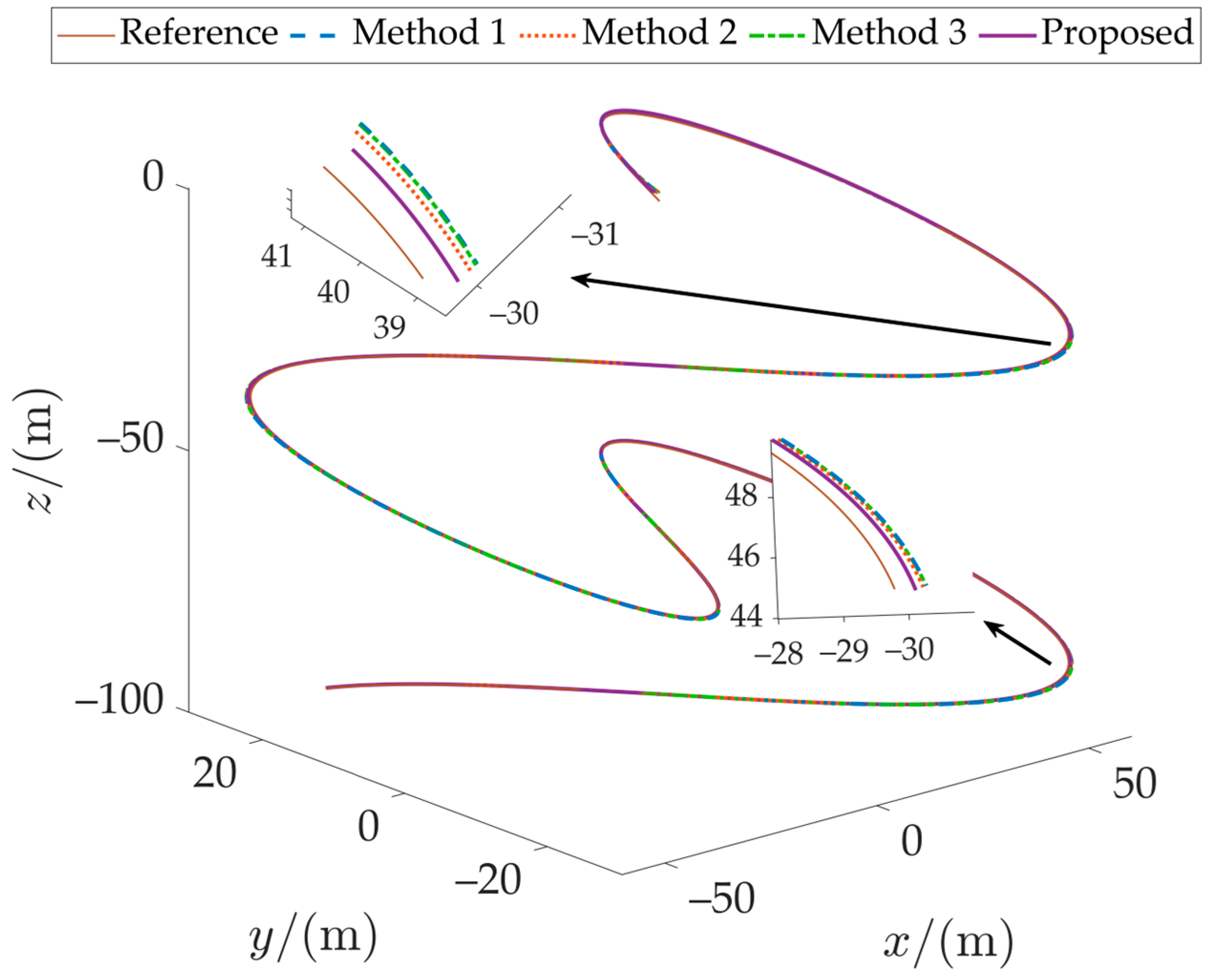
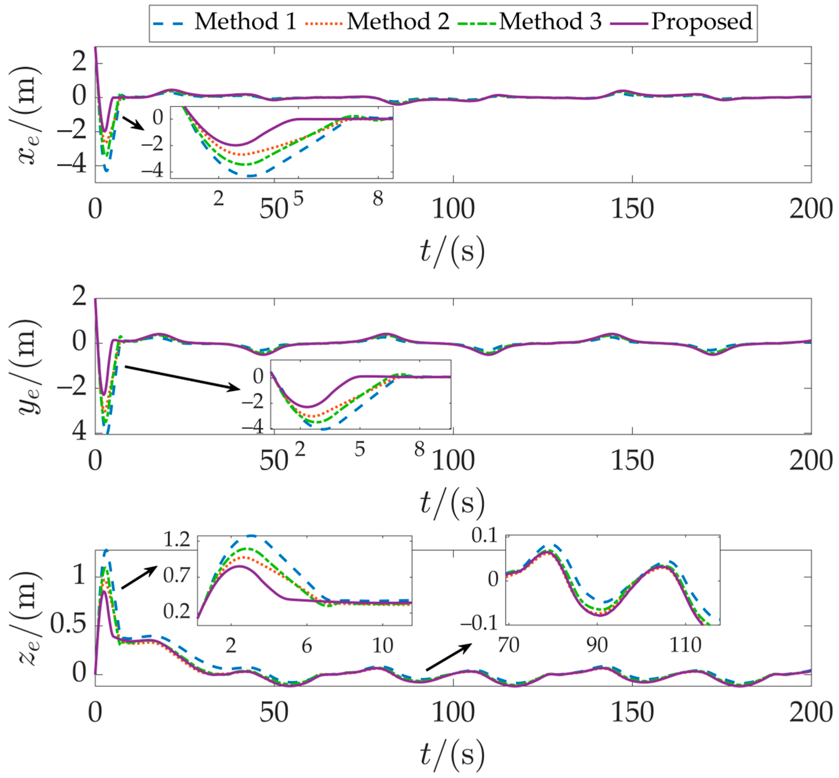
Figure 4 presents the trajectory tracking results of the underactuated AUV in three-dimensional space. It can be observed that all four control strategies achieve effective tracking of the desired trajectory, though differences exist in tracking accuracy. Figure 5 illustrates the positional error comparison among the methods. Method 1 exhibits the largest error amplitude, followed by Method 3. While Method 2 shows improvement over the baseline method, its overall error remains higher than that of the proposed method.
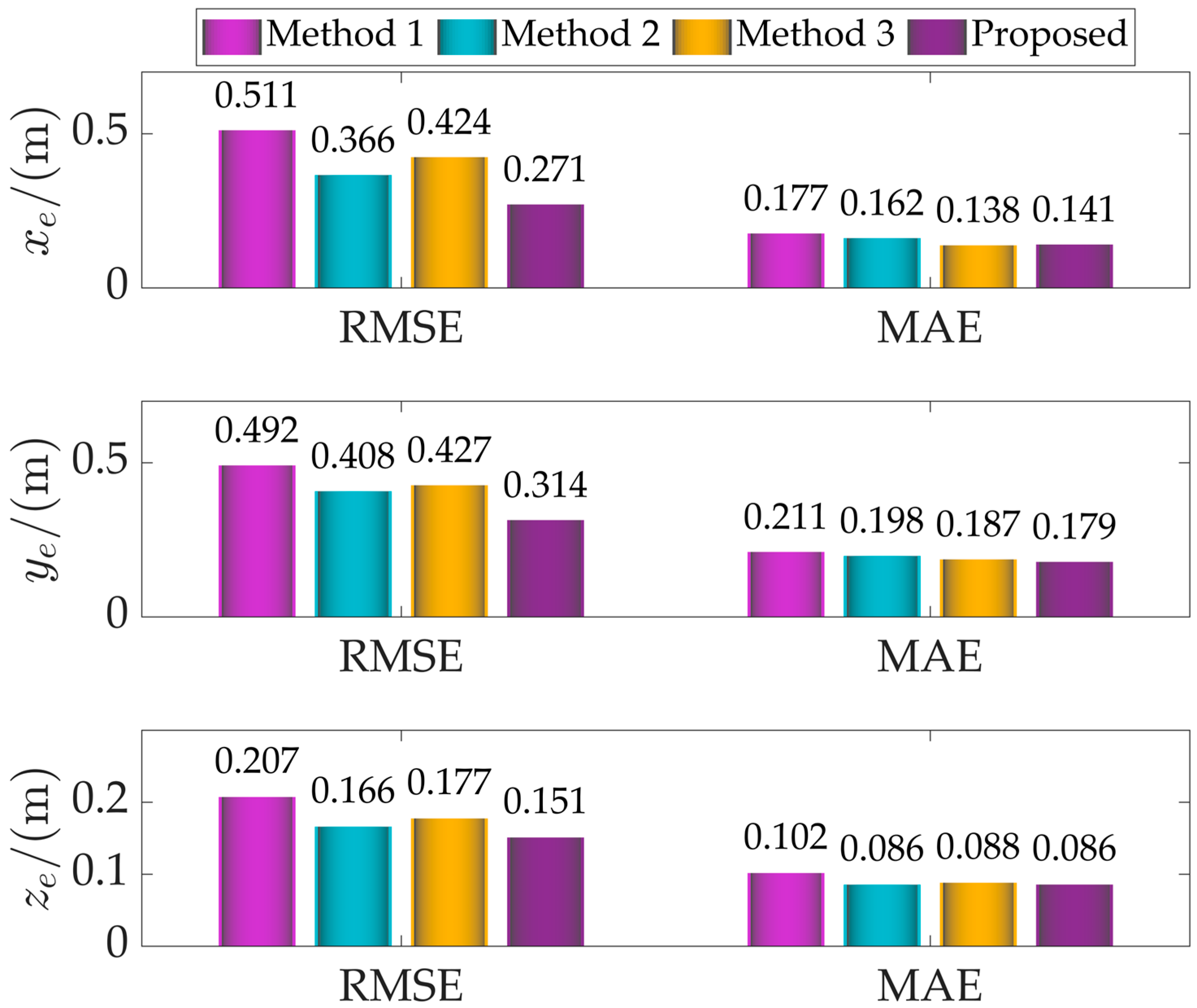
For quantitative evaluation, root mean square error (RMSE) and mean absolute error (MAE) were employed as performance metrics, with results shown in Figure 6. The proposed method achieves optimal values for both metrics, while Method 1 performs the worst. Notably, Method 2 exhibits significant fluctuations during both initial and later stages.
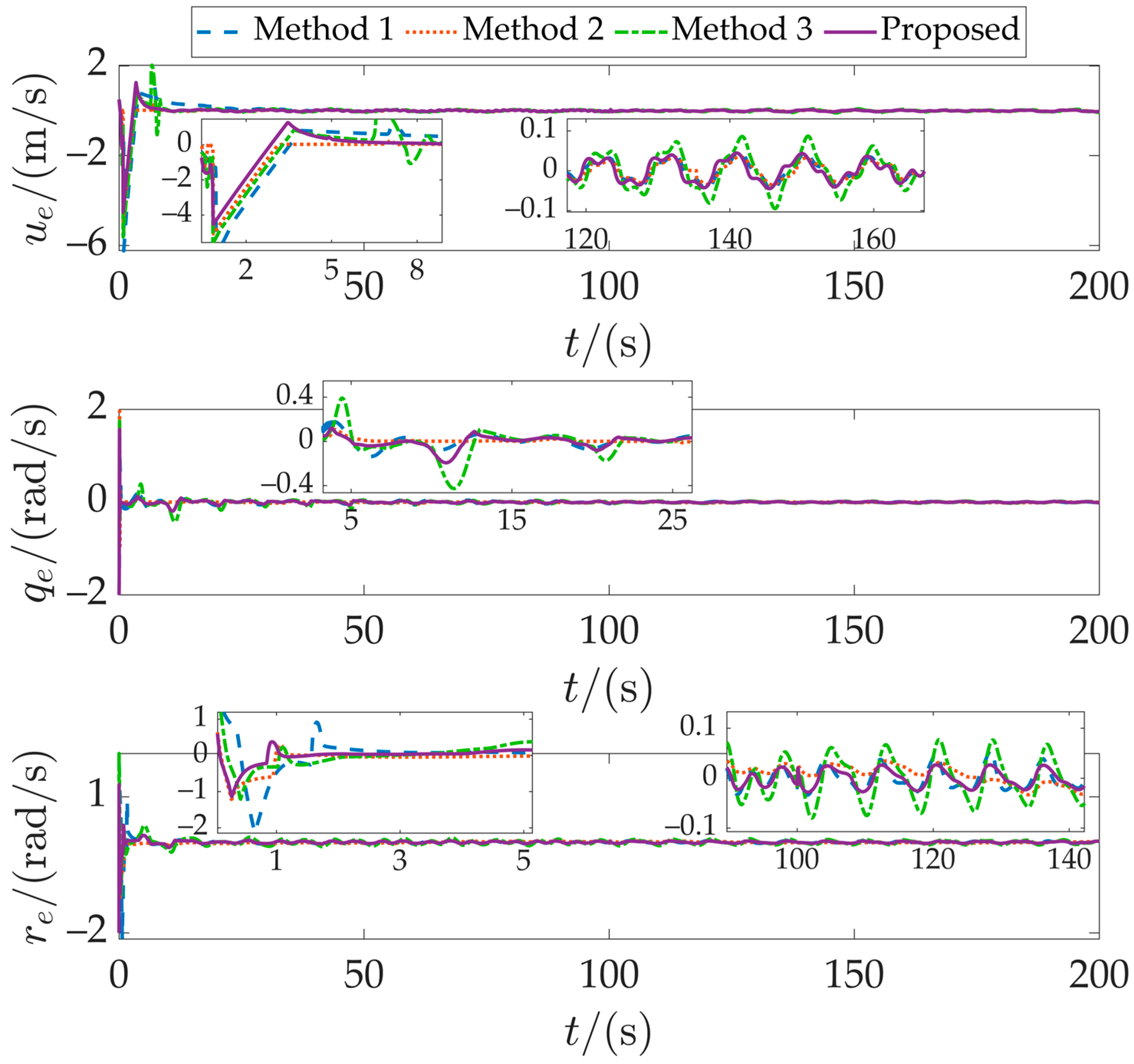
Figure 7 presents the velocity tracking error results. The proposed method responds rapidly and stabilizes near the desired velocity, demonstrating superior dynamic tracking capability and steady-state performance. In contrast, Methods 1 and 3 show substantial velocity fluctuations, with Method 3 exhibiting more pronounced oscillations under disturbances.
To further evaluate observer performance, Figure 8 displays the disturbance estimation results for the three observers: (a) fractional-order sliding mode observer (FOSMO), (b) integer-order sliding mode observer, and (c) extended state observer (ESO). Overall, all three methods capture the general disturbance trends, but with notable differences in detail. The integer-order sliding mode observer shows significant estimation bias with substantial fluctuations and drift. ESO exhibits phase lag in estimation, particularly failing to accurately track rapidly varying disturbances (e.g., in the x-direction). In contrast, the proposed FOSMO achieves stable and precise estimation of external disturbances across all directions, rapidly converging to true values even during abrupt disturbance changes. The FOSMO introduces a memory-weighted estimation that achieves a balance between fast transient response and smooth steady-state behavior, enabling accurate and low-noise disturbance reconstruction even under abrupt changes. The FOTSMC, on the other hand, modulates the switching dynamics through fractional-order surfaces, suppressing high-frequency chattering. When combined, the two modules yield more precise disturbance compensation and smoother control actions, which explains the reduced tracking error observed in Figure 5 and Figure 7.
Overall, the fractional-order design enhances disturbance estimation accuracy and robustness. Compared with ESO-based methods, the proposed FOSMO-FOTSMC maintains high tracking precision and stability even under strong, time-varying disturbances.

5.2. Case 2: Formation Tracking Performance Verification

This case comprehensively evaluates formation control and communication efficiency under dynamic formation transitions and event-triggered communication. The formation consists of one leader and three followers, where the leader tracks the figure-eight helical path from case 1 and periodically broadcasts reference positions. Followers exchange local information and generate their own desired trajectories using the distributed consensus mechanism.
The simulation consists of two phases:
Phase 1 (0–100 s): The followers maintain a planar linear formation behind the leader. Formation values are given by d 10 = 3 , 6 , 0 T , d 20 = 3 , 0 , 0 T , d 30 = 3 , 6 , 0 T .
Phase 2 (100–200 s): The formation transitions to a spatial triangular shape (delta formation), with the leader at the center. Formation values are given by d 10 = 0 , 6 , 5 T , d 20 = 0 , 0 , 5 T , d 30 = 0 , 6 , 5 T .
The initial bit state of the leader is x 0 , y 0 , z 0 , θ 0 , ψ 0 T = 3 , 2 , 0 , 0 , 0.1 T , and the initial velocity is u 0 , v 0 , w 0 , q 0 , r 0 T = 0.5 , 0 , 0 , 0 , 0 T . The initial bit state of the two followers is 3 , 0 , 0 , 0 , 0 T , 5 , 2 , 0 , 0 , 0 T , 3 , 1 , 0 , 0 , 0 T and the initial velocity is 1 . 5 , 0 , 0 , 0 , 0 T . The environmental disturbance is set as
τ d 1 = 13 sin 0.3 t cos 0.5 t τ d 4 = 15 cos 0.7 t cos 0.2 t τ d 5 = 12 sin 0.5 t cos 0.3 t
To validate the effectiveness of the event-triggered mechanism and its communication efficiency, this study designs two comparative scenarios:
1. Formation tracking under periodic communication: The initial communication topology is set as AUV1 ↔ AUV2 ↔ AUV3. During t = 120–150 s, the link between Follower 1 and Follower 2 is disconnected, along with the direct connection between the leader and Follower 3. These links are restored at t = 150 s to assess the system’s ability to maintain formation under partial communication.
2. Formation tracking under dynamic event-triggered communication: Initial conditions remain identical to the periodic communication case. However, information exchange occurs only when predefined triggering conditions are met. The upper and lower limits for the event trigger threshold in the simulation are set to 0.2 m and 0.5 m.
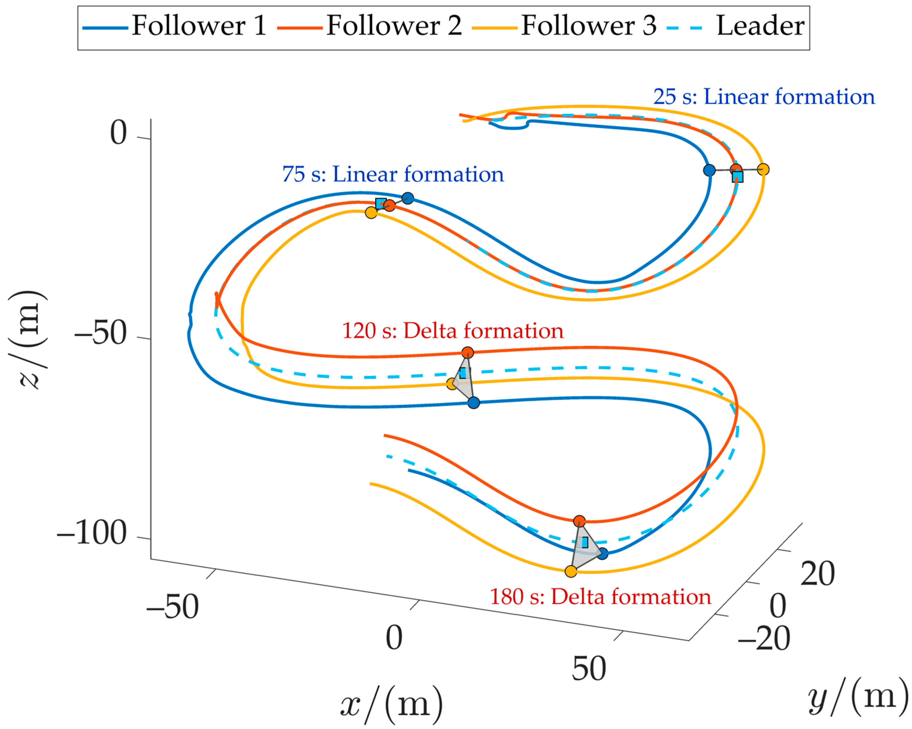
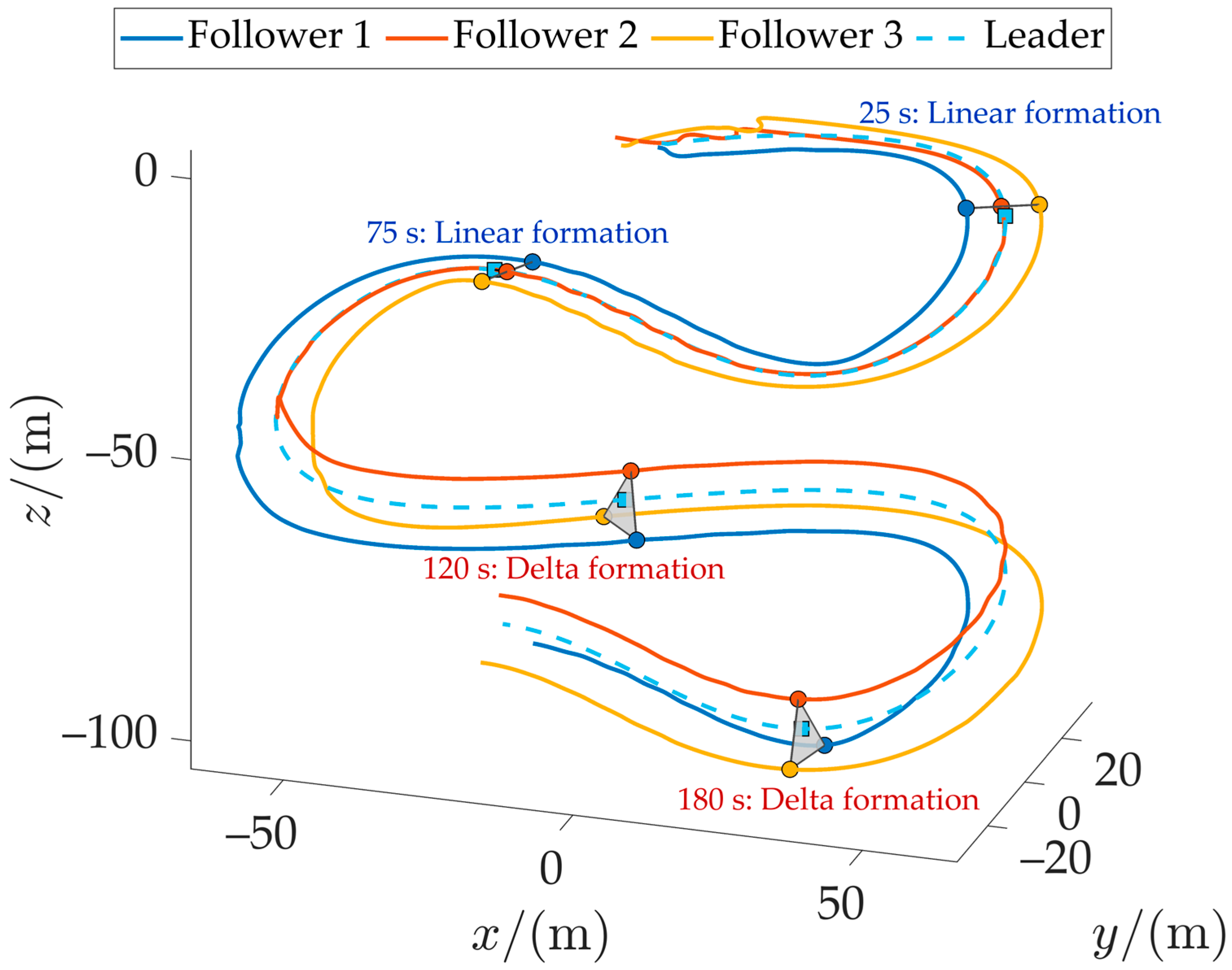
Figure 9 and Figure 10 illustrate the formation tracking performance of the four AUVs in three-dimensional space and horizontal projections, respectively. Different colored symbols indicate AUV positions at selected time instants (squares denote the leader, circles represent followers), with the gray area marking the formation coverage region of the followers. The formation remains stable in both straight-line and triangular configurations. The designed controller ensures rapid convergence to the desired trajectories. Although initial deviations occur due to starting position and formation errors, the system stabilizes quickly.
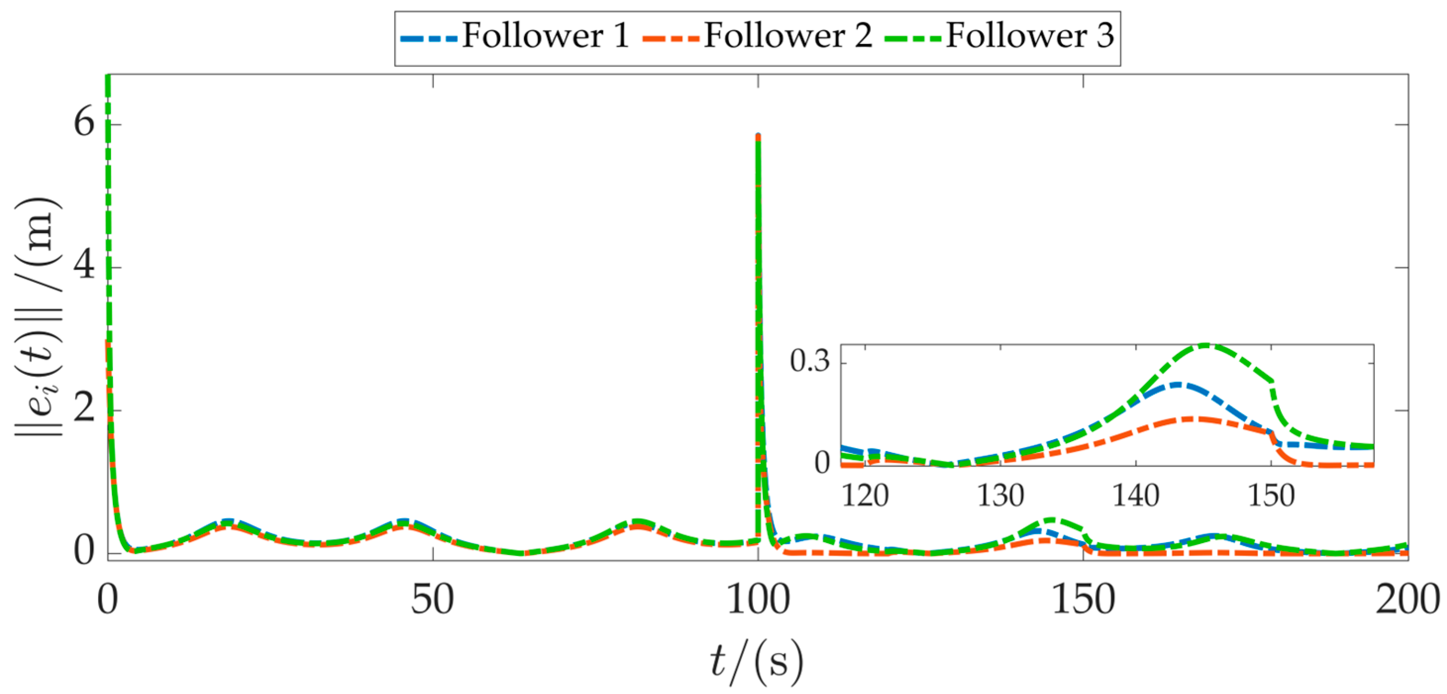
Figure 11 shows the formation error curves of the three followers. Errors increase slightly during the initial phase due to large starting deviations but are rapidly regulated within the threshold range through the trajectory negotiation mechanism. At t = 100 s, when the formation shape changes, errors spike transiently but recover to a stable state quickly. Between 120 s and 150 s, during the communication topology change, Follower 3 exhibits slightly larger fluctuations than Followers 1 and 2, which aligns with the loss of partial neighbor information due to link disconnections. Nevertheless, all errors remain within acceptable bounds, confirming the distributed robustness of the algorithm.
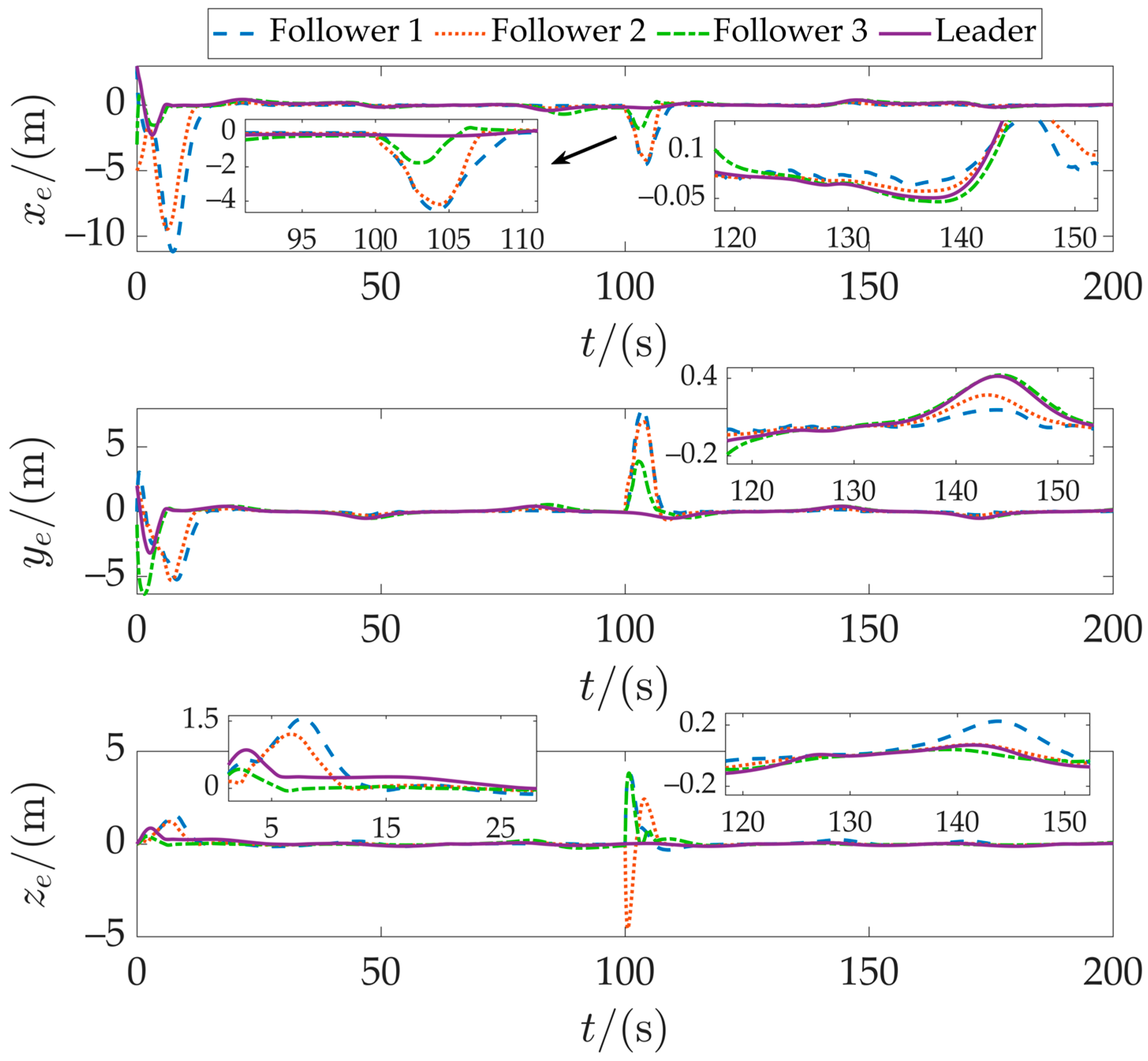
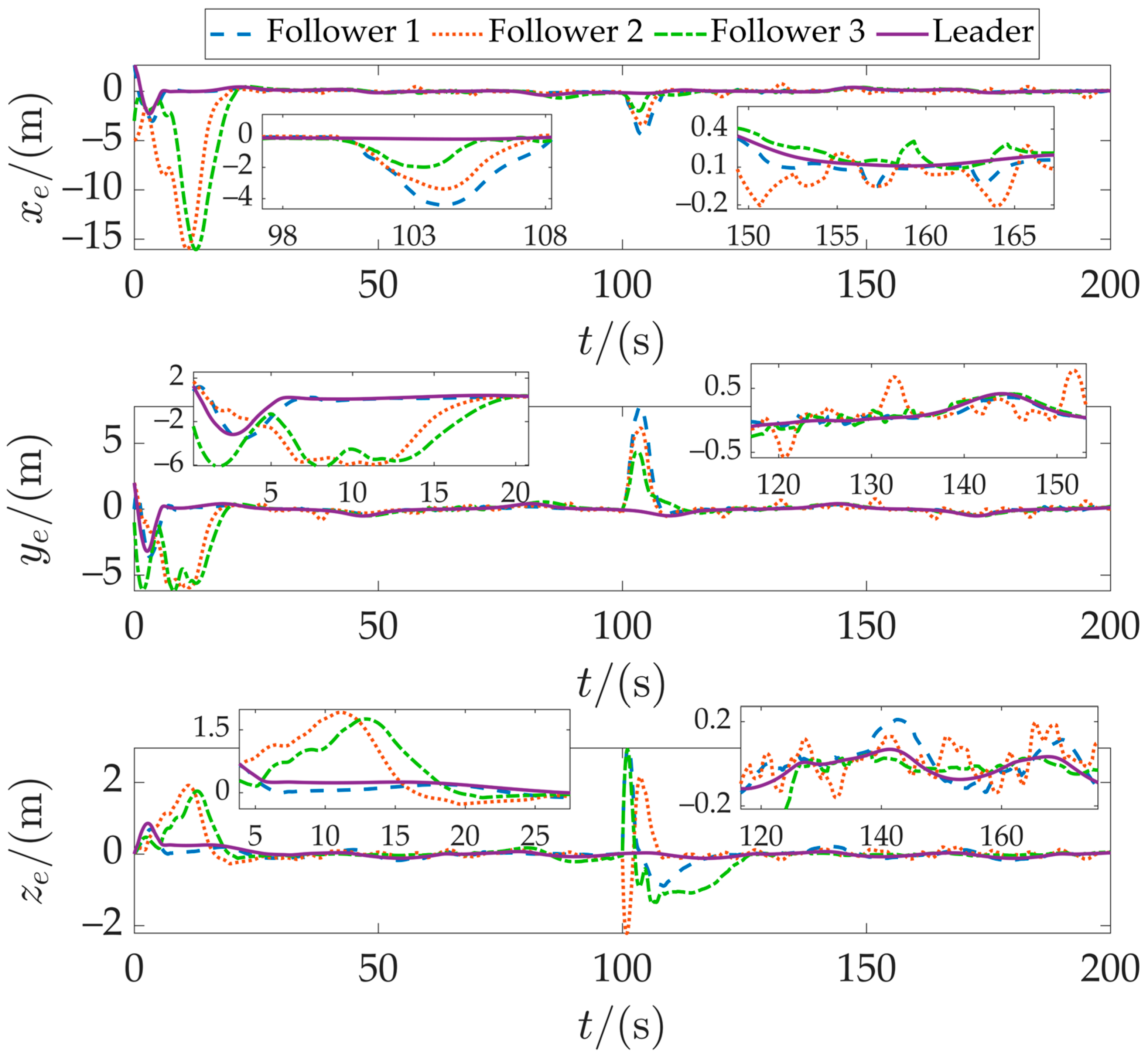
Figure 12 further presents the position tracking errors of all four AUVs. The leader shows small and stable tracking errors. The followers initially exhibit larger errors owing to their deviated initial positions but converge rapidly. A brief error surge occurs during the formation switch at t = 100 s, reflecting transient effects from trajectory reconfiguration, yet the system promptly restores tracking accuracy. The magnified view of the 120–150 s interval confirms that no error divergence occurs even under degraded communication, demonstrating consistent tracking performance under constrained conditions.
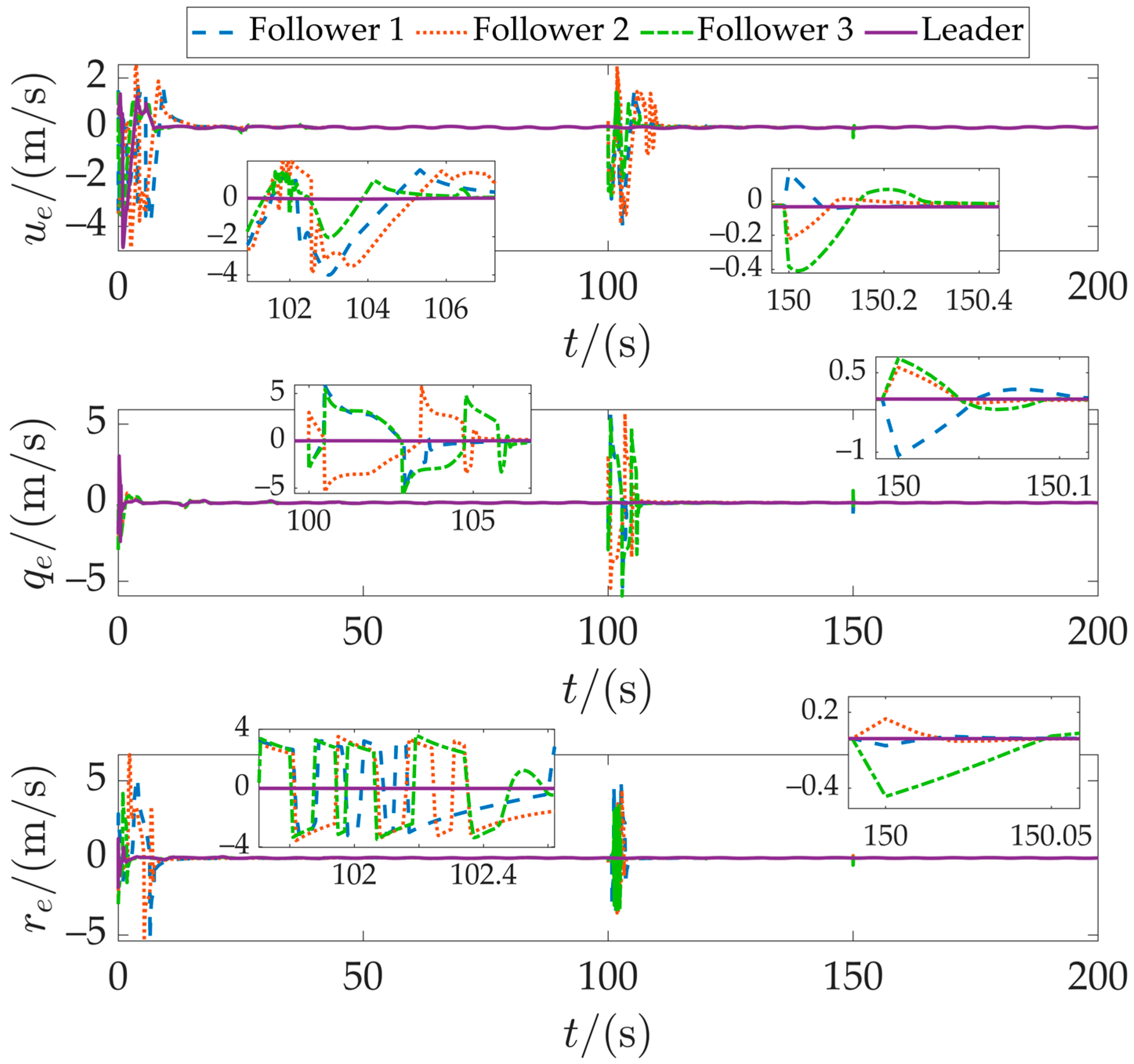
Figure 13 depicts the velocity error profiles. Despite starting from different initial positions, all AUVs rapidly reached steady-state operation. A transient oscillation in velocity error is observed during the formation reconfiguration at t =1 00 s, reflecting necessary speed adjustments to align with the new formation geometry. The system demonstrated effective recovery, with errors converging to zero shortly after this transition. An enlarged view of the topology restoration phase around t = 150 s reveals minor velocity fluctuations caused by communication link recovery. These disturbances were suppressed within 0.5 s without propagating to position tracking errors, confirming the robustness and disturbance rejection capability of the proposed formation coordination controller.
Figure 14, Figure 15, Figure 16, Figure 17, Figure 18 and Figure 19 present the simulation results under the dynamic event-triggered communication mechanism. Figure 14 and Figure 15 show the formation evolution of the four AUVs in three-dimensional space and on the horizontal plane, respectively, using the same color coding and annotation conventions as in the periodic communication case. It can be observed that under event-triggered communication, the overall formation remains stable, with all AUVs converging rapidly to the desired trajectory. However, due to the discontinuous nature of information updates introduced by the triggering mechanism, the resulting trajectories exhibit slightly more fluctuation and are less smooth than those under periodic communication. Despite this, the system maintains strong dynamic coordination and high formation accuracy.
Figure 16 shows the position tracking error curves of the four AUVs. The three followers exhibit larger error amplitudes during both the initial transient phase and the formation switching at t = 100 s, along with slightly extended convergence times, compared to the periodic communication case. This behavior results from the reduced frequency of neighbor information updates under the event-triggered mechanism. As the negotiated reference trajectory updates only when communication is triggered, it responds discontinuously to changes in state errors, leading to temporary fluctuations when errors remain within the triggering threshold and no communication occurs. Overall, the event-triggered mechanism achieves a significant reduction in communication frequency at the cost of a minor degradation in tracking accuracy.
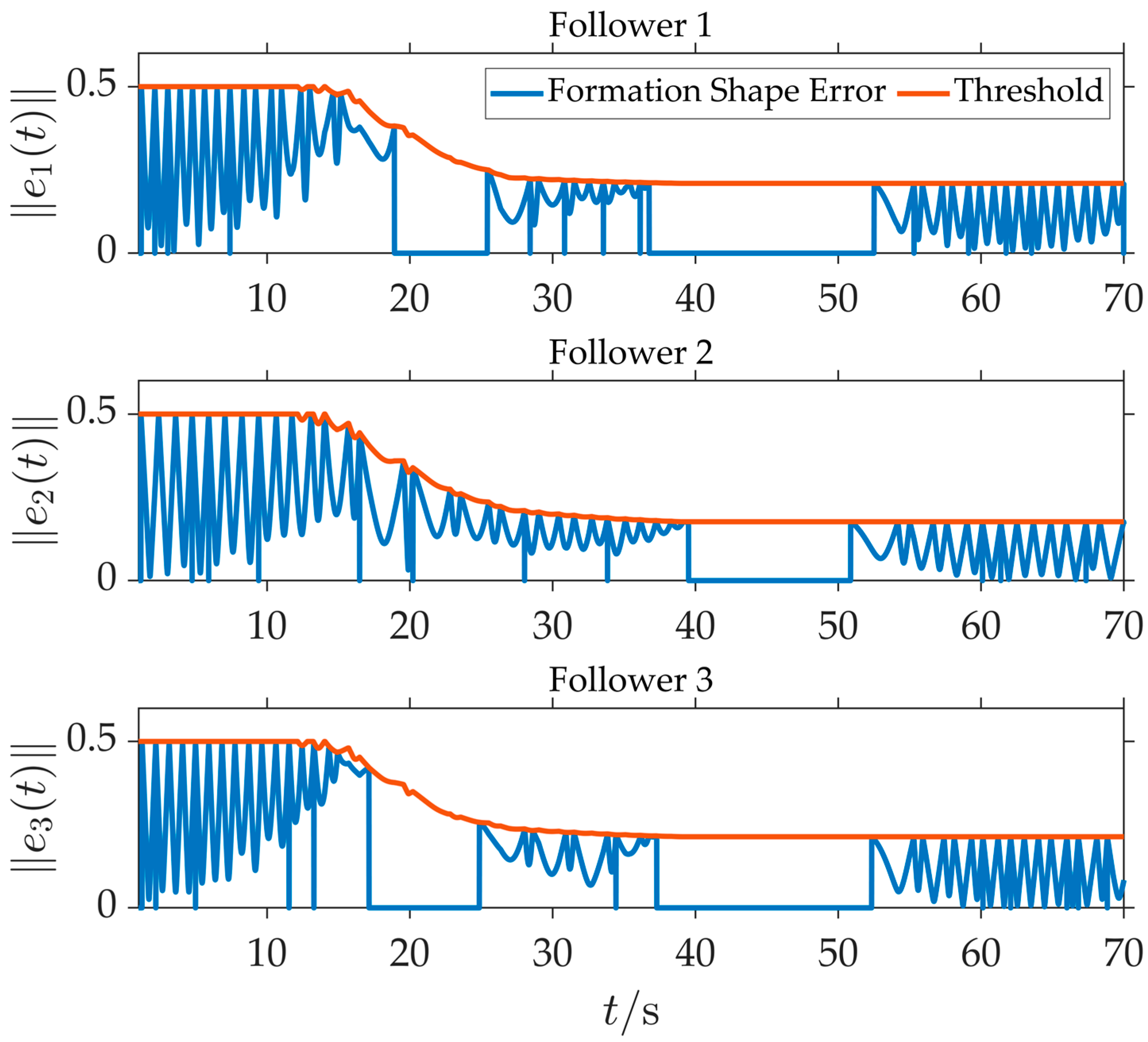
To further illustrate the working pattern of the event-triggered mechanism, Figure 17 zooms in on the time interval from t = 1 s to t = 70 s, which covers the transition from the transient phase to steady-state operation. The figure clearly reveals a typical triggering pattern: frequent controller updates during high-error periods (e.g., the initial phase) to ensure fast convergence, followed by significantly longer triggering intervals as the system enters steady state. This pattern demonstrates the mechanism’s ability to prolong communication silence during low-error periods, thereby effectively reducing the communication load.
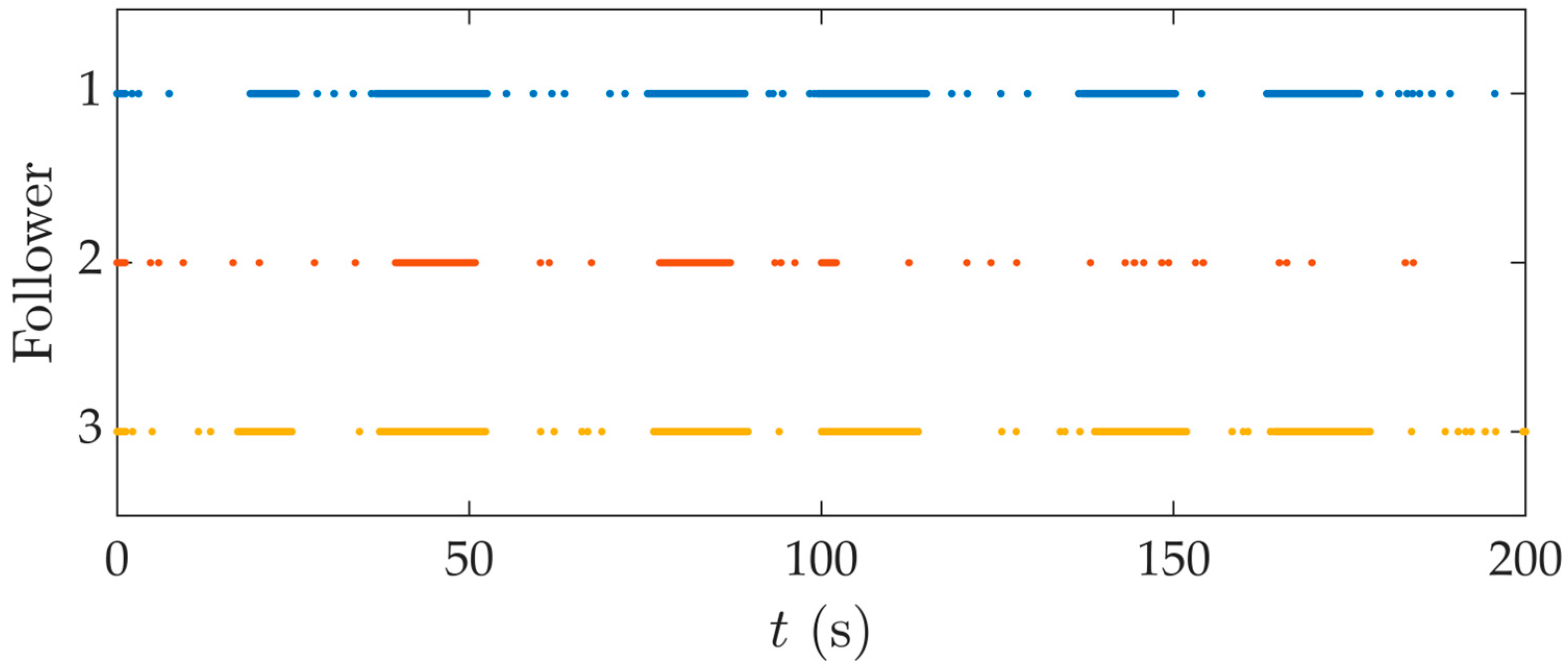
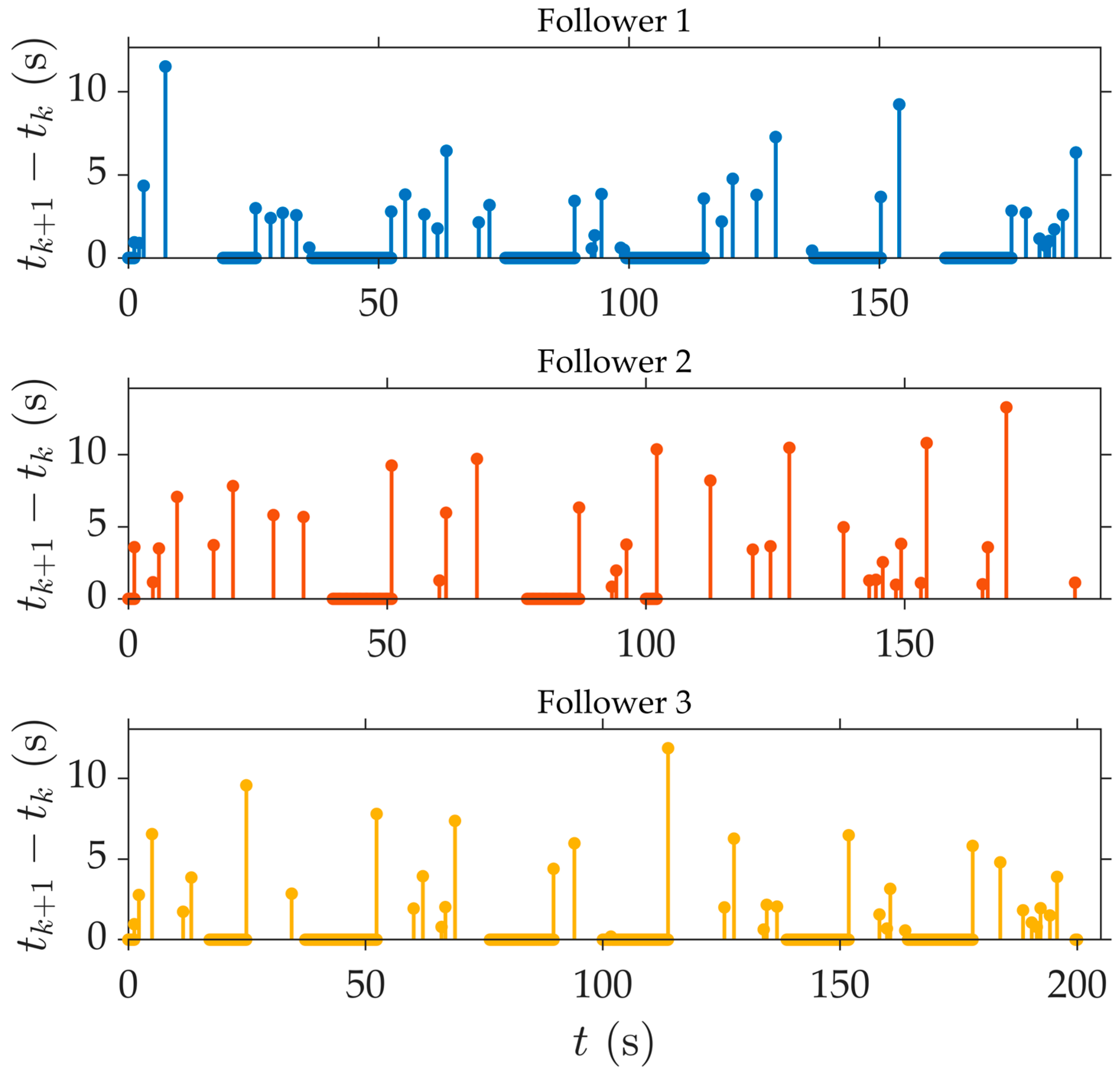
Figure 18 and Figure 19 further illustrate the behavior of the dynamic event triggering mechanism. Figure 18 shows the distribution of trigger moments for three followers throughout the entire operational cycle. Figure 19 presents the variation curve of time intervals between trigger moments. The control strategy based on dynamic triggering increases the trigger interval, thereby reducing the number of triggers, verifying the characteristic of dynamically adjusting trigger frequency according to system state. As summarized in Table 1, the total number of triggering instances under the dynamic event-triggered mechanism decreased by 65.2%, 87.5%, and 65.8%, respectively, compared to the periodic communication scheme. These results confirm that the proposed triggering strategy significantly reduces communication overhead while preserving control performance.
In summary, the simulation results comprehensively validate the effectiveness and robustness of the proposed method under dynamic formation changes, communication topology variations, and event-triggered communication. The system consistently maintains formation stability with limited communication resources, achieving high-precision trajectory tracking and substantial communication savings.
6. Conclusions

This paper presents a distributed cooperative formation control strategy for underactuated AUVs operating in complex marine environments. The method integrates a fractional-order sliding mode observer (FOSMO) and a fractional-order terminal sliding mode controller (FOTSMC) within a hierarchical “consensus–tracking” architecture.
The FOSMO enhances disturbance estimation precision through the memory characteristics of fractional calculus, while the FOTSMC guarantees finite-time convergence and strong robustness. A dynamic event-triggered communication mechanism is further introduced to adaptively regulate transmission frequency according to state errors, significantly reducing communication load and energy consumption. Two simulation cases validate the effectiveness of the proposed approach. In trajectory tracking tests, the FOSMO+FOTSMC scheme demonstrates superior performance in both accuracy and disturbance rejection compared to integer-order SMC and other fractional-order variants. In formation scenarios, the method reliably handles formation switching and communication topology changes, with the event-triggered mechanism reducing communication frequency by 65.2–87.5% relative to time-triggered setups, without compromising steady-state formation precision.
Future work will address communication delays and packet loss in underwater acoustic channels, explore asynchronous triggering and adaptive parameter optimization, and conduct hardware-in-the-loop and sea trials to further evaluate real-world performance and energy efficiency.

Author Contributions

Conceptualization, L.H.; resources, Y.Z.; methodology, S.L.; software, B.L. and M.X.; writing—original draft preparation, Z.Y. and C.B. All authors have read and agreed to the published version of the manuscript.

Funding

This research was funded by the Armament and Equipment Advance Research Project of the Central Military Commission, by the Fundamental Research Program of Shanxi Province, grant number 202303021212190, by the 2025 Shanxi Province Graduate Practice and Innovation Project Funding, grant number 2025SJ297 and 2025SJ025.

Data Availability Statement

Data are contained within the article.

Acknowledgments

The authors would like to express their sincere gratitude to the reviewers for their valuable time and professionalism. The reviewers’ critical comments and suggestions for improvement played a key role in enhancing the quality and completeness of this paper, enabling this study to be presented to a wider audience in a more rigorous form.

Conflicts of Interest

The authors declare no conflicts of interest.

Appendix A

Table A1. Parameters of the prototype.
ParametersValueParametersValue
M kg 33.68 X u ˙ kg –0.93
I y y kg m 2 3.54 Y v ˙ kg –35.5
I z z kg m 2 3.54 Z w ˙ kg –35.5
X u kg / s –8.105 X u | u | kg / m –3.9
Y v kg / s –62.025 Y v | v | kg / m –131
Z w kg / s –61.701 Z w | w | kg / m –131
M q kg m 2 / rad s –42.637 M q ˙ kg m 2 / rad –4.88
N r kg m 2 / rad s –48.776 N r ˙ kg m 2 / rad –4.88
M q | q | kg m 2 / rad 2 –188 N r | r | kg m 2 / rad 2 –94

Appendix B

This appendix provides a complete mathematical description and parameter settings for the three benchmark methods used for comparison in Simulation Case 1 of Section 5. All parameters have been finely tuned in the same simulation environment to ensure fairness in performance comparison.

Appendix B.1. Method 1: Integer-Order SMO + Conventional Sliding Mode Control

Integer-order SMO is designed as
Δ ^ ˙ = k v v ˜ ˙ + L ^ sign S + k 1 S α 1 sign S + k 2 S α 2 sign S + k 3 S L ^ ˙ = k 4 S
where k v , k 1 , k 2 , k 3 , k 4 are positive definite gain matrices. The sliding surface is designed as
S = k v v ˜ + v ˜ ˙
the convergence law is designed as
S ˙ = k 1 S α 1 sign S k 2 S α 2 sign S k 3 S
Conventional sliding mode control law is designed as
τ = M k U U e K 1 sign σ K 2 σ H v Δ ^ + U ˙ d
where K 1 , K 2 , and K U denote the positive definite gain matrices to be designed. The sliding surface is designed as
σ = U e + k U 0 t U e d τ
the convergence law is designed as
σ ˙ = K 1 sign σ K 2 σ
Parameter set: k v = 5 , 6 , 6 T , k 1 = 10 , 10 , 10 T , k 2 = 10 , 10 , 10 T , k 3 = 12 , 12 , 12 T , k 4 = 10 , 10 , 10 T , K U = 0 . 8 , 1 . 1 , 1 . 2 T , K 1 = 8 , 8 , 9 T , K 2 = 1 . 5 , 1 . 5 , 2 . 5 T .

Appendix B.2. Method 2: FOSMO + Terminal Sliding Mode Control

This benchmark utilizes the FOSMO presented in Section 3.2 of the main text (Equation (24)).
Terminal sliding mode control law is designed as
τ = M L ^ 3 sign σ K 1 σ β sign σ K 2 σ H v Δ ^ + U ˙ d / 1 + k U ω U e ω 1 L ^ ˙ 3 = K 3 σ
where K 1 , K 2 , K 3 , K U , ω , and β denote the positive definite gain matrices to be designed. The sliding surface is designed as
σ = U e + k U U e ω sign U e
the convergence law is designed as
σ ˙ = K 1 σ β sign σ K 2 σ
Parameter set: k v = 15 , 15 , 15 T , k 1 = 15 , 15 , 15 T , k 2 = 10 , 10 , 10 T , k 3 = 5 , 5 , 5 T , k 4 = 15 , 15 , 15 T , α 1 = 5 7 , 5 7 , 5 7 T , α 2 = 5 3 , 5 3 , 5 3 T , m = 0 . 5 , 0 . 5 , 0 . 5 T , K U = 1 . 5 , 1 . 5 , 1 . 5 T , K 1 = 5 . 5 , 5 . 5 , 5 . 5 T , K 2 = 4 . 5 , 4 . 5 , 4 . 5 T , K 3 = 0 . 8 , 1 . 2 , 1 . 2 T , ω = 0 . 7 , 0 . 7 , 0 . 7 T , β = 0 . 5 , 0 . 5 , 0 . 5 T .

Appendix B.3. Method 3: ESO + FOTSMC

ESO is designed as
e = z 1 υ z ˙ 1 = H v + z 2 + M 1 τ λ 1 e z ˙ 2 = λ 2 e
where λ 1 and λ 2 denote the positive definite gain matrices to be designed. z 1 and z 2 are the observed values of v = u , v , w , q , r T and v ˙ , respectively.
This benchmark utilizes the FOTSMC presented in Section 3.3 of the main text (Equation (32)).
Parameter set: λ 1 = 4 , 5 , 5 , 5 , 4 T , λ 2 = 25 , 20 , 20 , 18 , 18 T , K U = 0 . 5 , 0 . 5 , 0 . 5 T , K 1 = 5 . 5 , 5 . 5 , 5 . 5 T , K 2 = 4 . 5 , 4 . 5 , 4 . 5 T , K 3 = 0 . 8 , 1 . 2 , 1 . 2 T , ω = 0 . 7 , 0 . 7 , 0 . 7 T , β = 0 . 5 , 0 . 5 , 0 . 5 T , n = 0 . 5 , 0 . 5 , 0 . 5 T .

References

  1. He, L.; Xie, M.; Zhang, Y. A Review of Path Following, Trajectory Tracking, and Formation Control for Autonomous Underwater Vehicles. Drones 2025, 9, 286. [Google Scholar] [CrossRef]
  2. Li, J.; Zhang, G.; Jiang, C.; Zhang, W. A Survey of Maritime Unmanned Search System: Theory, Applications and Future Directions. Ocean Eng. 2023, 285, 115359. [Google Scholar] [CrossRef]
  3. Cheng, C.; Sha, Q.; He, B.; Li, G. Path Planning and Obstacle Avoidance for AUV: A Review. Ocean Eng. 2021, 235, 109355. [Google Scholar] [CrossRef]
  4. Er, M.J.; Gong, H.; Liu, Y.; Liu, T. Intelligent Trajectory Tracking and Formation Control of Underactuated Autonomous Underwater Vehicles: A Critical Review. IEEE Trans. Syst. Man Cybern. Syst. 2024, 54, 543–555. [Google Scholar] [CrossRef]
  5. Cao, W.; Yan, J.; Yang, X.; Luo, X.; Guan, X. Communication-Aware Formation Control of AUVs with Model Uncertainty and Fading Channel via Integral Reinforcement Learning. IEEECAA J. Autom. Sin. 2023, 10, 159–176. [Google Scholar] [CrossRef]
  6. Wang, H.; Tong, S.; Wang, A.; Zhang, W.; Hu, Z.; Peng, Z. Heterogeneous Cross Domain Coordinated Control of ASV-AUV System for Maritime Search and Rescue. Ocean Eng. 2024, 306, 117950. [Google Scholar] [CrossRef]
  7. Liu, L.; Zhang, L.; Pan, G.; Zhang, S. Robust Yaw Control of Autonomous Underwater Vehicle Based on Fractional-Order PID Controller. Ocean Eng. 2022, 257, 111493. [Google Scholar] [CrossRef]
  8. Alagoz, B.B.; Tepljakov, A.; Petlenkov, E.; Yeroglu, C. Multi-Loop Model Reference Proportional Integral Derivative Controls: Design and Performance Evaluations. Algorithms 2020, 13, 38. [Google Scholar] [CrossRef]
  9. He, L.; Zhang, Y.; Xie, M.; Yuan, Z.; Bai, C. Three-Dimensional Trajectory Tracking Control of Underactuated AUV Based on Fractional-Order PID and Super-Twisting Extended State Observer. Fractal Fract. 2025, 9, 580. [Google Scholar] [CrossRef]
  10. Zhang, Z.; Wu, Y. Adaptive Fuzzy Tracking Control of Autonomous Underwater Vehicles with Output Constraints. IEEE Trans. Fuzzy Syst. 2021, 29, 1311–1319. [Google Scholar] [CrossRef]
  11. Yu, C.; Xiang, X.; Wilson, P.A.; Zhang, Q. Guidance-Error-Based Robust Fuzzy Adaptive Control for Bottom Following of a Flight-Style AUV with Saturated Actuator Dynamics. IEEE Trans. Cybern. 2020, 50, 1887–1899. [Google Scholar] [CrossRef]
  12. He, L.; Zhang, Y.; Li, S.; Li, B.; Yuan, Z. Three-Dimensional Path Following Control for Underactuated AUV Based on Ocean Current Observer. Drones 2024, 8, 672. [Google Scholar] [CrossRef]
  13. He, L.; Zhang, Y.; Fan, G.; Liu, Y.; Wang, X.; Yuan, Z. Three-Dimensional Path Following Control of Underactuated AUV Based on Nonlinear Disturbance Observer and Adaptive Line-of-Sight Guidance. IEEE Access 2024, 12, 83911–83924. [Google Scholar] [CrossRef]
  14. Wang, L.; Lu, Y.; Zhang, L.; Cui, B.; Chen, F.; Liang, B.; Yu, L.; Yu, S. Position and Attitude Control of Multi-Modal Underwater Robots Using an Improved LADRC Based on Sliding Mode Control. Sensors 2025, 25, 6010. [Google Scholar] [CrossRef] [PubMed]
  15. Shojaei, K. Neural Network Formation Control of Underactuated Autonomous Underwater Vehicles with Saturating Actuators. Neurocomputing 2016, 194, 372–384. [Google Scholar] [CrossRef]
  16. Wang, H.; Su, B. Event-Triggered Formation Control of AUVs with Fixed-Time RBF Disturbance Observer. Appl. Ocean Res. 2021, 112, 102638. [Google Scholar] [CrossRef]
  17. Liu, H.; Zeng, C.; Tian, X.; Mai, Q. Intelligent Emotional Learning Control System with Prescribed Performance and Dynamic Event-Triggered Mechanism for Trajectory Tracking of Underactuated AUV. Ocean Eng. 2025, 342, 122983. [Google Scholar] [CrossRef]
  18. Liu, X.; Zhang, M.; Yao, F. Adaptive Fault Tolerant Control and Thruster Fault Reconstruction for Autonomous Underwater Vehicle. Ocean Eng. 2018, 155, 10–23. [Google Scholar] [CrossRef]
  19. He, L.; Xie, M.; Zhang, Y.; Li, S.; Li, B.; Yuan, Z.; Bai, C. Formation Control of Underactuated AUVs Using a Fractional-Order Sliding Mode Observer. Fractal Fract. 2025, 9, 465. [Google Scholar] [CrossRef]
  20. Rong, S.; Wang, H.; Li, H.; Sun, W.; Gu, Q.; Lei, J. Performance-Guaranteed Fractional-Order Sliding Mode Control for Underactuated Autonomous Underwater Vehicle Trajectory Tracking with a Disturbance Observer. Ocean Eng. 2022, 263, 112330. [Google Scholar] [CrossRef]
  21. Liu, L.; Wang, D.; Peng, Z. ESO-Based Line-of-Sight Guidance Law for Path Following of Underactuated Marine Surface Vehicles with Exact Sideslip Compensation. IEEE J. Ocean. Eng. 2017, 42, 477–487. [Google Scholar] [CrossRef]
  22. Xie, M.; Wu, Z.; Huang, H. Low-Complexity Formation Control of Marine Vehicle System Based on Prescribed Performance. Nonlinear Dyn. 2024, 112, 18311–18332. [Google Scholar] [CrossRef]
  23. Wu, J.; Liu, H.; Li, B.; Li, J.; Li, M. Precision Trajectory Control in Underwater Vehicle-Manipulator Systems Using Advanced Sliding Mode Techniques and State Estimation. Ocean Eng. 2025, 318, 120129. [Google Scholar] [CrossRef]
  24. Luo, W.; Liu, S. Disturbance Observer Based Nonsingular Fast Terminal Sliding Mode Control of Underactuated AUV. Ocean Eng. 2023, 279, 114553. [Google Scholar] [CrossRef]
  25. Meng, C.; Zhang, W.; Du, X. Finite-Time Extended State Observer Based Collision-Free Leaderless Formation Control of Multiple AUVs via Event-Triggered Control. Ocean Eng. 2023, 268, 113605. [Google Scholar] [CrossRef]
  26. Xiong, X.; Xiang, X.; Duan, Y.; Yang, S. Adaptive SNDO-STSM Hierarchical Robust Control of Autonomous Underwater Vehicle: Theory and Experimental Validation. IEEE Trans. Ind. Electron. 2024, 71, 14351–14361. [Google Scholar] [CrossRef]
  27. Fei, J.; Feng, Z. Fractional-Order Finite-Time Super-Twisting Sliding Mode Control of Micro Gyroscope Based on Double-Loop Fuzzy Neural Network. IEEE Trans. Syst. Man Cybern. Syst. 2021, 51, 7692–7706. [Google Scholar] [CrossRef]
  28. Lunyang, L.; Yuxiang, C.; Chunliang, Y.; Hong, Z.; Hong, X.; Yiyang, X.; Guodong, Z. Motion Control of Negative-Lift AUV Based on Disturbance Compensation Nonlinear Model Predictive Control with Extended State Observation. Ocean Eng. 2025, 329, 121145. [Google Scholar] [CrossRef]
  29. Wang, Z.; Wang, Y.; Sun, Y.; Qin, H. Fixed-Time Dynamic Event-Triggered Three-Dimensional Formation Control for Multi-AUV System with Disturbance Observer. Ocean Eng. 2024, 308, 118165. [Google Scholar] [CrossRef]
  30. Zhang, Y.; Sun, X.; Liu, W.; Wang, Y.; Miao, J. Performance-Triggering Frequency Trade-off Bearing-Based Formation Control for AUVs: A Dynamic Event-Triggered Strategy with MIET. Ocean Eng. 2025, 340, 122318. [Google Scholar] [CrossRef]
  31. Fei, J.; Wang, Z.; Fang, Y. Self-Evolving Recurrent Chebyshev Fuzzy Neural Sliding Mode Control for Active Power Filter. IEEE Trans. Ind. Inform. 2023, 19, 2729–2739. [Google Scholar] [CrossRef]
  32. Millán, P.; Orihuela, L.; Jurado, I.; Rubio, F.R. Formation Control of Autonomous Underwater Vehicles Subject to Communication Delays. IEEE Trans. Control Syst. Technol. 2014, 22, 770–777. [Google Scholar] [CrossRef]
  33. Bian, J.; Xiang, J. Three-Dimensional Coordination Control for Multiple Autonomous Underwater Vehicles. IEEE Access 2019, 7, 63913–63920. [Google Scholar] [CrossRef]
  34. Benzerrouk, A.; Adouane, L.; Martinet, P. Stable Navigation in Formation for a Multi-Robot System Based on a Constrained Virtual Structure. Robot. Auton. Syst. 2014, 62, 1806–1815. [Google Scholar] [CrossRef]
  35. Li, J.; Yuan, R.; Zhang, H. Research on Multiple AUVs Formation Control Algorithm Based on Leader-Follower Method. Yi Qi Yi Biao Xue Bao Chin. J. Sci. Instrum. 2019, 40, 237–246. [Google Scholar] [CrossRef]
  36. Yan, T.; Xu, Z.; Yang, S.X. Consensus Formation Tracking for Multiple AUV Systems Using Distributed Bioinspired Sliding Mode Control. IEEE Trans. Intell. Veh. 2023, 8, 1081–1092. [Google Scholar] [CrossRef]
  37. Mokhtari, M.; Taghizadeh, M.; Mazare, M. Distributed Consensus and Formation Control of Multi-AUV Systems under Actuator Faults and Switching Topology. Eur. J. Control 2024, 79, 101006. [Google Scholar] [CrossRef]
  38. Li, J.; Tian, Z.; Zhang, H. Discrete-Time AUV Formation Control with Leader-Following Consensus under Time-Varying Delays. Ocean Eng. 2023, 286, 115678. [Google Scholar] [CrossRef]
  39. Liang, H.; Fu, Y.; Kang, F.; Gao, J.; Qiang, N. A Behavior-Driven Coordination Control Framework for Target Hunting by UUV Intelligent Swarm. IEEE Access 2020, 8, 4838–4859. [Google Scholar] [CrossRef]
  40. Tan, G.; Zhuang, J.; Zou, J.; Wan, L. Coordination Control for Multiple Unmanned Surface Vehicles Using Hybrid Behavior-Based Method. Ocean Eng. 2021, 232, 109147. [Google Scholar] [CrossRef]
  41. Wang, L.; Zhu, D.; Pang, W.; Luo, C. A Novel Obstacle Avoidance Consensus Control for Multi-AUV Formation System. IEEECAA J. Autom. Sin. 2023, 10, 1304–1318. [Google Scholar] [CrossRef]
  42. Monje, C.A.; Chen, Y.; Vinagre, B.M.; Xue, D.; Feliu, V. Fractional-Order Systems and Controls. In Advances in Industrial Control; Springer: London, UK, 2010; ISBN 978-1-84996-334-3. [Google Scholar]
  43. Jin, B. Fractional Differential Equations: An Approach via Fractional Derivatives; Applied Mathematical Sciences; Springer International Publishing: Cham, Switzerland, 2021; ISBN 978-3-030-76042-7. [Google Scholar]
  44. Fossen, T.I. Handbook of Marine Craft Hydrodynamics and Motion Control; Wiley: Hoboken, NJ, USA, 2021; ISBN 978-1-119-57505-4. [Google Scholar]
  45. Lopez-Ramirez, F.; Efimov, D.; Polyakov, A.; Perruquetti, W. Finite-Time and Fixed-Time Input-to-State Stability: Explicit and Implicit Approaches. Syst. Control Lett. 2020, 144, 104775. [Google Scholar] [CrossRef]
  46. Yu, H.; Chen, T. On Zeno Behavior in Event-Triggered Finite-Time Consensus of Multiagent Systems. IEEE Trans. Autom. Control 2021, 66, 4700–4714. [Google Scholar] [CrossRef]
Figure 1. Schematic diagram of 3D trajectory tracking.
Fractalfract 09 00755 g001
Figure 2. Schematic diagram of trajectory tracking control.
Fractalfract 09 00755 g002
Figure 3. Schematic diagram of formation control.
Fractalfract 09 00755 g003
Figure 4. Tracking following in case 1.
Fractalfract 09 00755 g004
Figure 5. Position error in case 1.
Fractalfract 09 00755 g005
Figure 6. Comparison of error quantification in case 1.
Fractalfract 09 00755 g006
Figure 7. Comparison of speeds in case 1.
Fractalfract 09 00755 g007
Figure 8. Disturbance estimation situation in case 1. (a) Proposed method. (b) Method 1. (c) Method 2.
Fractalfract 09 00755 g008
Figure 9. Formation 3D following situation.
Fractalfract 09 00755 g009
Figure 10. x-y plane projection following situation.
Fractalfract 09 00755 g010
Figure 11. State error.
Fractalfract 09 00755 g011
Figure 12. Position tracking error.
Fractalfract 09 00755 g012
Figure 13. Velocity error.
Fractalfract 09 00755 g013
Figure 14. Formation 3D following situation.
Fractalfract 09 00755 g014
Figure 15. x-y plane projection following situation.
Fractalfract 09 00755 g015
Figure 16. Position tracking error.
Fractalfract 09 00755 g016
Figure 17. State error and threshold.
Fractalfract 09 00755 g017
Figure 18. Distribution of event trigger timing.
Fractalfract 09 00755 g018
Figure 19. Event trigger intervals.
Fractalfract 09 00755 g019
Table 1. Comparison of trigger counts.
NameEvent Trigger CountsPeriodic Communication CountsReduction Ratio
Follower 1695520,00065.2%
Follower 2249520,00087.5%
Follower 3683720,00065.8%
Disclaimer/Publisher’s Note: The statements, opinions and data contained in all publications are solely those of the individual author(s) and contributor(s) and not of MDPI and/or the editor(s). MDPI and/or the editor(s) disclaim responsibility for any injury to people or property resulting from any ideas, methods, instructions or products referred to in the content.