Abstract
The propagation of stress waves and the evolution of blasting-induced cracks in discontinuous rock mass are strongly influenced by joint characteristics. This study focuses on intersecting-joint rock mass and employs the explicit dynamic finite element method with the RHT constitutive model to simulate blasting. The effects of joint thickness and angle on stress wave behavior and crack propagation were systematically analyzed, and fractal theory was applied using MATLAB 2023b to quantitatively characterize crack distribution. The results indicate that joint thickness significantly affects stress wave transmission and reflection: thicker joints enhance reflected wave intensity while attenuating transmitted waves due to successive reflections within the infill. Joint angle controls the number of reflections between joints, with smaller angles producing stronger interactions. Thickness and angle jointly govern crack propagation, causing cracks to concentrate between the borehole and joints. Thickness primarily determines crack density on the blast-facing side of horizontal joints, whereas joint angle exerts deflecting and inhibiting effects. Fractal analysis shows that the fractal dimension of cracks varies nonlinearly with joint characteristics, with higher values in the borehole-to-joint region, increasing with thickness and angle. These findings provide quantitative insight into stress wave–joint interactions and guidance for optimizing blasting design in jointed rock mass, helping to minimize overbreak and underbreak and improve excavation safety.
1. Introduction
Drill-and-blast methods, owing to their high construction efficiency and cost-effectiveness, are widely applied in underground engineering projects [,,,]. The presence of discontinuities, including cracks, joints, and faults, within a rock mass significantly alters its mechanical properties compared with those of intact rock [,,]. During blasting excavation, the interaction between explosive stress waves and structural discontinuity is complex and significantly affects the excavation profile. Therefore, investigating the behavior of stress waves and the development of blasting-induced cracks in jointed rock under explosive loading is crucial for improving rock fragmentation and ensuring excavation safety.
The propagation of explosive stress waves across joints is primarily influenced by the explosive source parameters, the relative position between the joints and the source, the mechanical property contrast between the rock and the joint filling material, and the joint thickness. These factors lead to variations in stress wave propagation and, consequently, changes in the cracks propagation patterns within the rock mass [,,,]. Previous studies have addressed this problem through theoretical analysis, laboratory experiments, and numerical simulations. In theoretical studies, the propagation of explosive stress waves in jointed rock is often analyzed using discontinuum methods. Li et al. [] employed the B-B model to describe the nonlinear normal and shear behavior of joints and developed corresponding propagation equations to analyze stress waves incident on joints at arbitrary angles. Unlike models that simplify joint thickness as a zero-thickness interface, stress waves incident at different angles on filled joints undergo deflected propagation. Considering the effect of thickness, Li et al. [,] proposed a thin-layer interface model for filled rock joints based on the Displacement Discontinuity Method (DDM) [,] and the concept of thin-layer interfaces [], which accounts for the influence of filled joints on transmitted and reflected waves under oblique incidence.
Experimental investigations have further examined the crack behavior of jointed rock under blasting [,]. Using wave-crack synchronous test systems combined with dynamic photoelasticity and dynamic caustic methods, these studies achieved synchronous measurement of stress wave propagation and crack evolution, providing direct insights into the propagation and superposition of explosive stress waves in jointed media. Other researchers [,] employed Crack Propagation Gauges (CPG) to record crack propagation characteristics, analyzing the crack velocity under various joint conditions and elucidating the interaction mechanisms between blasting-induced cracks and pre-existing joints.
Laboratory experiments can capture rock crack patterns, but the instantaneous nature of explosive loading and experimental limitations hinder a full understanding of how joint characteristics govern crack propagation. In contrast, numerical simulation provides substantial advantages in both efficiency and accuracy, rendering it an indispensable tool for investigating complex dynamic phenomena []. Finite Element Method (FEM) and Discrete Element Method (DEM) simulations have been used to explore the effects of joint distribution and characteristics on stress wave propagation and crack development [,,].
Most existing studies have focused on single or parallel joints, whereas joints in engineering rock mass are often irregular, disordered, and randomly distributed. Intersecting joints, formed by two joints meeting at arbitrary angles, more accurately represent real engineering conditions. Accordingly, this study employs the Riedel–Hiermaier–Thoma (RHT) damage constitutive model and the FEM software LS-DYNA R11.0 to develop a numerical model of jointed rock with filled intersecting joints subjected to blasting. The effects of varying joint characteristics on stress wave propagation and crack evolution are systematically investigated. Furthermore, fractal theory is applied to quantitatively characterize the spatial distribution of blasting-induced cracks, providing insight into the crack behavior of intersecting-joint rock under explosive loading. The findings offer scientific guidance for the design and implementation of blasting in jointed rock mass.
2. Numerical Simulation of Blasting in Intersecting-Joint Rock Mass
To investigate the influence of joint characteristics on stress wave propagation and crack development in intersecting-joint rock under blasting, a numerical model was developed using HyperMesh 2021 and subsequently analyzed in LS-DYNA R11.0.
In borehole blasting, the explosive charge typically assumes a columnar configuration, generating stress waves that propagate radially as cylindrical waves on coaxial wavefronts. This can be idealized as waves radiating outward from a line source on a plane perpendicular to the charge axis, forming circular wavefronts in the surrounding medium []. Consequently, when explosive stress waves encounter intersecting joints, normal (perpendicular) incidence occurs. Accordingly, the intersecting joints are modeled as the intersection of a horizontal joint and an inclined joint, with the angle between them defined as the joint angle. The joint surfaces are simplified as smooth planes, and the infill material is represented as an elastic continuous medium perfectly bonded to the surrounding rock on both sides.
2.1. Numerical Model Development
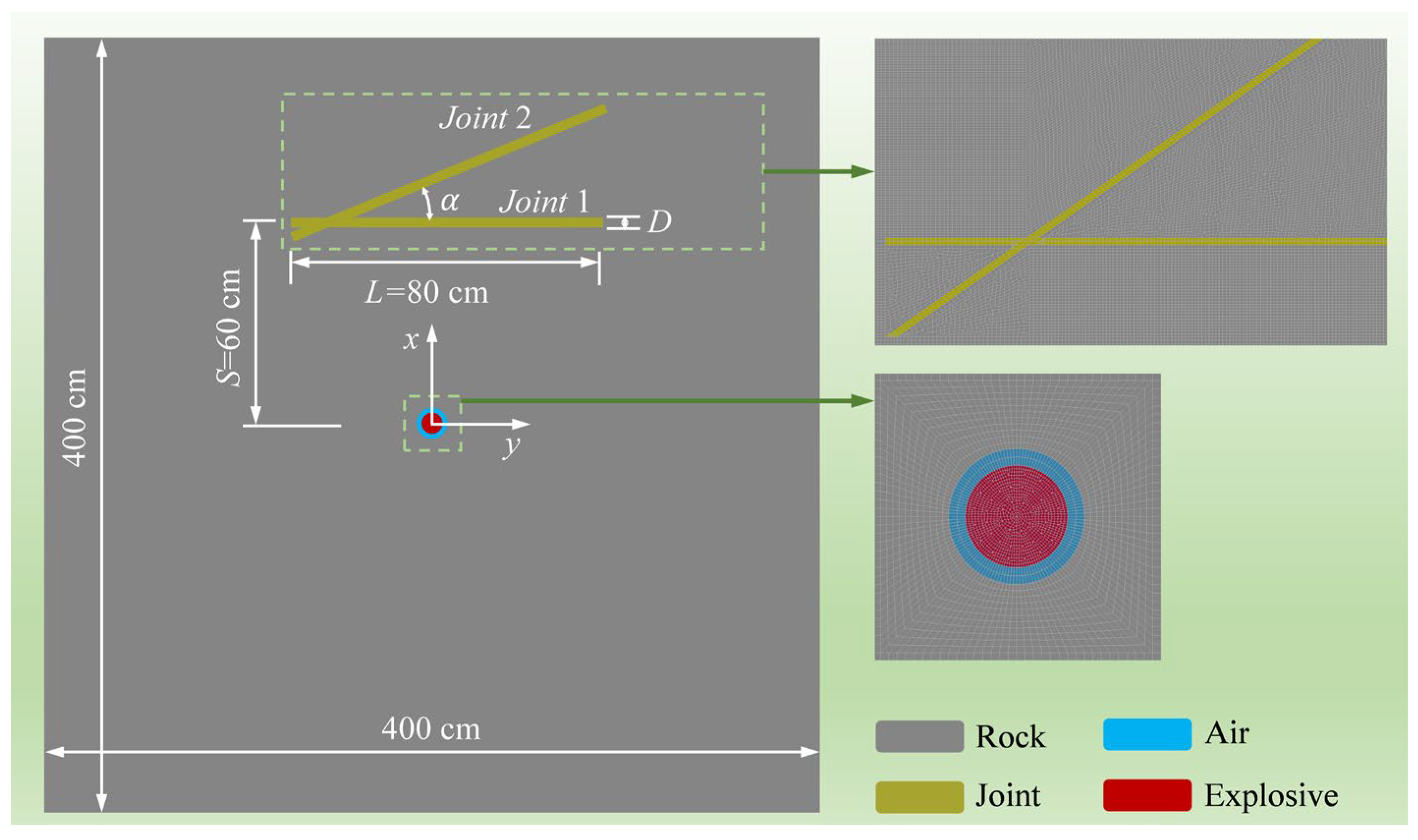
The propagation of stress waves within rock mass is often idealized as a plane strain problem. In this study, a quasi-two-dimensional model with dimensions of 400 cm × 400 cm × 0.4 cm was adopted, as illustrated in Figure 1. A displacement constraint was applied in the model’s normal direction (i.e., the z-direction), such that out-of-plane displacements are much smaller than in-plane displacements. Therefore, the model can effectively represent the plane strain condition of stress wave propagation. However, it should be noted that this simplified model cannot fully capture the complete three-dimensional effects around the borehole axis.
Figure 1.
Schematic diagram of the numerical model for blasting in intersecting-joint rock.
The borehole is positioned at the center of the model, with a set of filled intersecting joints located above it. The horizontal joint is designated as Joint 1 (J1), and the inclined joint as Joint 2 (J2), with the distance between J1 and the borehole (S) set to 60 cm and the joint length (L) set to 80 cm. A single-hole uncoupled charge configuration is employed, with a borehole radius of R = 2.0 cm and a charge radius of r = 1.5 cm.
In the model, J2 intersects J1 at a distance of 10 cm from the end of J1. The inclined joint induces complex stress wave transformations. To simplify the investigation of interactions between intersecting joints, only the right half of the cross-joint system is analyzed. As shown in Figure 1, when stress waves are incident from the left half, a portion can propagate to the right half; however, their paths are relatively long, and by the time they reach the right half, they are sufficiently far from the intersection, exerting negligible influence on the wave superposition near the joint intersection. Therefore, the left half is omitted from the analysis.
In this study, the joint angle (α) and the thickness of the joint infill material (hereafter referred to as joint thickness, D) were selected as the primary variables, while the length of J1 and its distance from the borehole were kept constant to maintain consistent incident wave (blast stress wave) conditions. The joint angle α was set to 5°, 15°, 25°, 35°, and 45° to investigate the influence of varying joint angles on stress wave propagation and crack response. When the joint infill thickness is much smaller than the wavelength of the blast stress wave, its effect on wave propagation can be neglected []. Therefore, the joint thicknesses were chosen to be comparable to or larger than the stress wave wavelength, with D set to 0.2 r, 0.4 r, and 0.6 r.
Since dynamic finite element simulation results are highly sensitive to mesh size, a hexahedral mesh was employed in the model. To minimize wave distortion, the maximum element size is generally kept below one-tenth of the stress wave wavelength (λ). To ensure the accuracy and stability of the numerical model, a mesh sensitivity analysis was performed. The results indicated that when the average mesh size ranged from 0.2 to 0.4 cm, the variation in the calculated results was within 5%. Therefore, to achieve a balance between computational accuracy and efficiency, the average mesh size was set to 0.4 cm in the simulations in this study, with local refinement implemented around the borehole.
To prevent severe mesh distortion, the model was established using the Arbitrary Lagrangian-Eulerian (ALE) coupling algorithm, in which the explosive and air were meshed with Eulerian elements, while the rock and filled joints were meshed with Lagrangian elements. The interface between the rock and explosive was modeled using the *CONSTRAINED_LAGRANGE_IN_SOLID keyword in LS-DYNA for ALE coupling. Non-reflective boundaries were applied to the surfaces surrounding the model to simulate an infinite rock domain, thereby preventing stress wave reflections at the boundaries from affecting the simulation results.
2.2. Parameters of Materials
2.2.1. RHT Model
The Riedel–Hiermaier–Thoma (RHT) constitutive model is widely used to describe the dynamic response of rock and concrete-like materials under large deformations and high strain rates, such as those induced by blasting, impact, or projectile penetration. Developed as an enhancement of the HJC constitutive model, the RHT model incorporates the third invariant of the deviatoric stress tensor, enabling qualitative identification of material deformation modes and stress states. It also captures key behaviors during material failure, including strain hardening, strain rate sensitivity, and compressive damage softening. Unlike the Holomquist-Johnson-Cook (HJC) or the Johnson-Holmquist (JH-2) models that primarily characterize the compressive damage of materials, the RHT constitutive model is a comprehensive tension–compression damage model that simultaneously accounts for strain-rate effects, strain hardening, and damage softening.
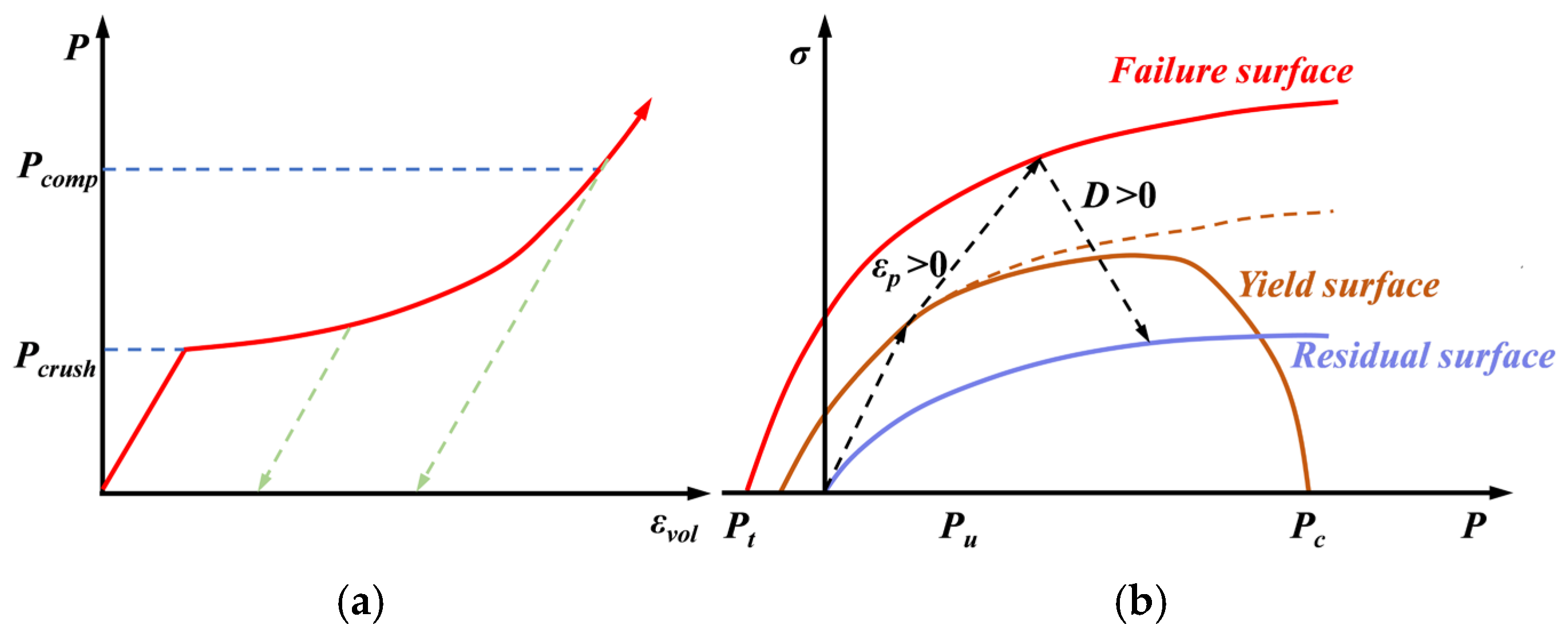
In the RHT constitutive model, the yield surface is defined by the uniaxial compressive strength (fc), the regularized yield function , and the William–Warnke function R3 [], as illustrated in Figure 2. The yield surface can be expressed as:
Figure 2.
Schematic diagram of RHT model []. (a) p-α equation of state; (b) Stress limit surfaces.
Here, the normalised pressure P* represents the ratio of pressure P to compressive strength fc, P* = P/fc, P = (σ1 + 2σ3)/3; s is the deviatoric stress tensor; is the plastic strain rate; represents the normalised plastic strain; θ is the Lode angle, which is defined by the second and third invariants of the deviatoric stress tensor; Fr is the dynamic increase factor. Granite is selected as the rock material for the numerical simulations in this study. The parameters [] are listed in Table 1.
Table 1.
RHT model parameters of rock.
2.2.2. Parameters of Explosive
Emulsion explosive No. 2 was selected as the explosive in this study. The explosive behavior was modeled using the *MAT_HIGH_EXPLOSIVE_BURN material model in LS-DYNA, combined with the Jones-Wilkins-Lee (JWL) equation of state (EOS) to describe the relationship among the volume, pressure, and energy of the detonation products. The JWL EOS is widely used to simulate explosives in rock mechanics due to its capability to accurately capture the dynamic expansion behavior of detonation products []. The EOS can be expressed as follows:
In the equation, Ve and E0 represent the relative volume and the specific energy of the detonation products, respectively, while the parameters ωe, Ae, Be, R1 and R2 are material constants. The calculation parameters [] are listed in Table 2.
Table 2.
Parameters of No. 2 emulsion explosive.
2.2.3. Parameters of the Filled Joints
Compared with the surrounding rock, the material filling the joints generally exhibits weaker mechanical properties, and the filled joints are usually considered as soft layers of finite thickness []. Therefore, soft rock was selected as the joint infill material. The *MAT_PLASTIC_KINEMATIC material model was employed, which accounts for strain rate effects and can effectively capture the dynamic mechanical response of the infill under explosive loading. Its constitutive equation is expressed as follows:
In the equation, σy and σ0 represent the yield strength and initial yield stress, respectively; denotes the strain rate; C and P are strain-rate related parameters; is the effective plastic strain; and EP is the plastic hardening modulus, which can be calculated from the elastic modulus Ej and the shear modulus Et, EP = EjEt/(Ej − Et). The specific calculation parameters [] are listed in Table 3.
Table 3.
Parameters of filled joints.
2.2.4. Parameters of Air
Air and explosive were treated as the fluid components in the ALE algorithm. In the simulations, the *MAT_NULL material model was employed in combination with the linear equation of state (*EOS_LINEAR_POLYNOMIAL) to describe their behavior. The air properties were defined based on the ideal gas assumption [], and the pressure was calculated as follows:
In the equation, P represents the internal energy; μ is the equation of state parameter; C0–C6 are material constants, with C4 and C5 set to 0.4 and the remaining constants set to 0; E denotes the internal energy, which is taken as 250 MPa; and the air density ρ is set to 1.225 g/cm3.
2.3. Validation of the Numerical Simulation
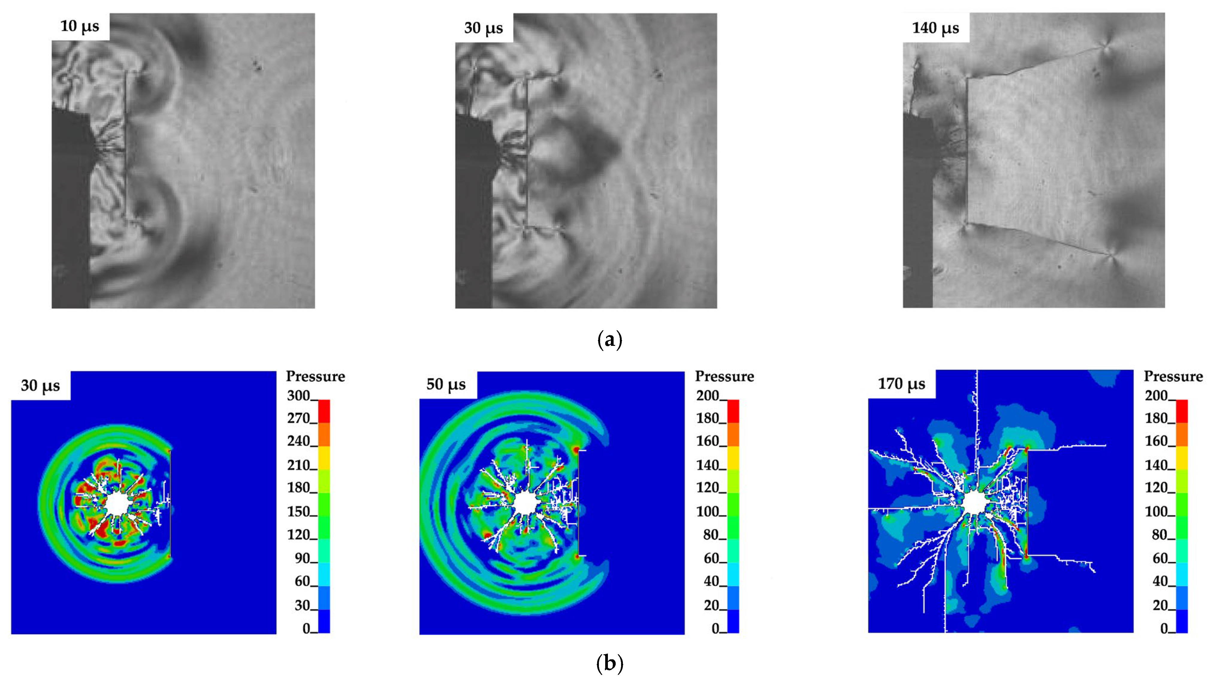
Based on literature [], the effectiveness and validity of the numerical simulation were verified through laboratory experiments. Figure 3 illustrates the propagation of explosive stress waves and the resulting crack development under different conditions.
Figure 3.
Comparison of model test and numerical simulation results. (a) model test results []; (b) numerical simulation results.
The experiments employed a dynamic photoelastic system consisting of a light source, a high-speed camera, an explosive loading device, a synchronization controller, and a photoelastic instrument. The high-speed camera captured two consecutive images at intervals of 10 μs. The specimens were 5 mm-thick polymethyl methacrylate (PMMA) plates with a pre-drilled borehole of 6 mm in diameter and a 60 mm longitudinal joint, with the distance from the borehole to the joint set at 25 mm. Lead azide (Pb(N3)2) explosive was placed in the borehole and detonated using a probe high-voltage discharge.
The presence of the joint significantly altered the propagation path of the explosive stress wave. As shown in Figure 3, after detonation, the stress wave propagated outward in a circular pattern and was first reflected at the center of the joint. Subsequently, the stress wave traveled toward the joint ends, where diffraction occurred, producing localized stress concentrations. This led to the initiation and propagation of wing cracks at the joint ends, as illustrated in Figures. The numerical simulation successfully reproduced the entire process of stress wave propagation and crack development, thereby validating the accuracy and reliability of the simulation.
3. Analysis of Numerical Simulation Results
3.1. Propagation of Blasting-Induced Cracks
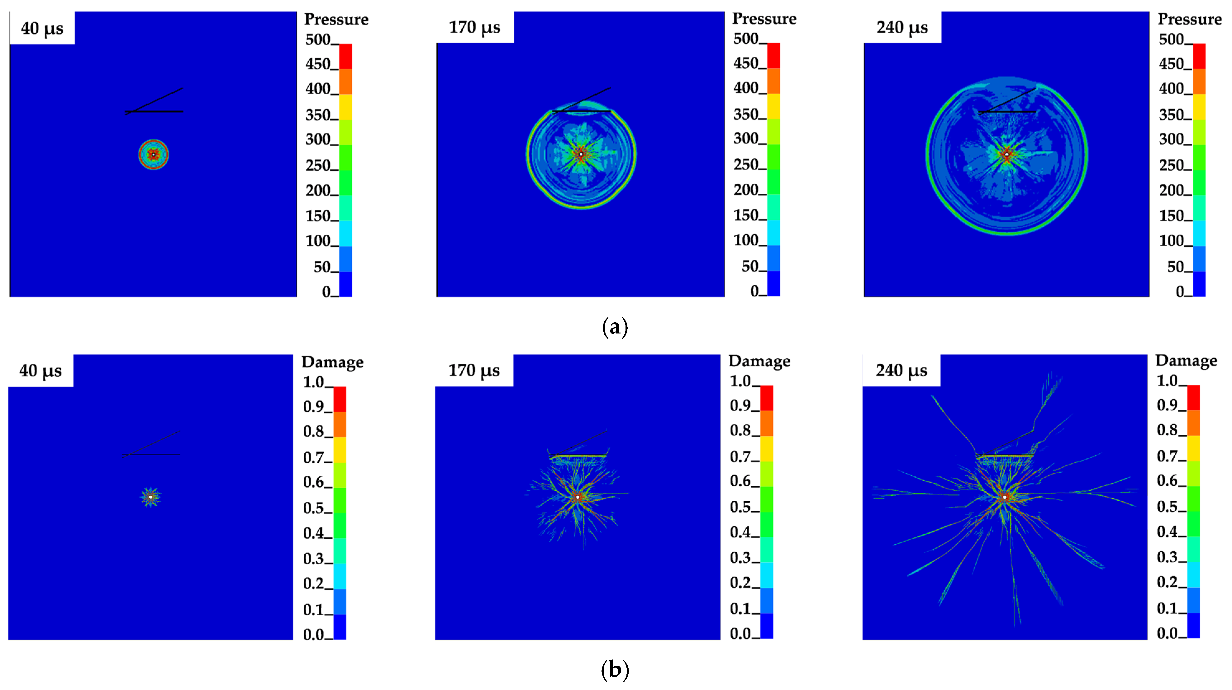
Since the overall blasting response of rock mass is generally consistent across different joint configurations, the case with a joint angle of 25° and a joint thickness of 0.4 r was selected as a representative example to illustrate the crack evolution in intersecting-joint rock under blasting. The stress distribution and crack propagation at 40 μs, 170 μs and 240 μs are shown in Figure 4.
Figure 4.
Blasting-Induced Crack in Intersecting-joint. (a) Propagation of Stress Waves; (b) Propagation of Blasting-Induced Crack.
Immediately after detonation, the shock wave exerts a load on the borehole wall that greatly exceeds the dynamic compressive strength of the rock, leading to crushing and the formation of a pulverized zone around the borehole. In general, the pulverized zone radius ranges from approximately 2–5 R; however, due to the uncoupled charge configuration adopted in this study, the zone was reduced to about 1.5–2 R. Beyond this region, the shock wave attenuates into a stress wave that propagates outward in concentric circular fronts centered on the borehole.
At 120 μs, the compressive stress wave reaches the center of J1, where it generates reflected and transmitted waves along the joint plane. The reflected wave travels back toward the borehole, producing numerous short cracks on the explosion-facing side of J1 that continue to develop during subsequent propagation. Superposition between the reflected and incident waves forms an arch-shaped wavefront, which alters both the direction and length of radial cracks when they intersect, creating clear differences compared with the crack patterns observed in joint-free regions. The transmitted wave, meanwhile, propagates across J1 with little distortion, indicating that the filled joint has only a minor influence on waveform evolution. Approximately 50 μs later, this transmitted wave impinges on the inclined joint (J2), producing new transmitted and reflected waves. Multiple reflections between J1 and J2 promote tensile failure of the rock located between the joints.
As the stress wave continues to interact with the joints, diffraction occurs at the ends of J1 and J2. The diffracted waves superimpose with the transmitted wave, giving rise to local stress concentrations and initiating wing cracks at the joint tips. Notably, wing cracks at the J2 tip are more easily triggered and longer than those at the J1 tip, implying that the inclined joint tip induces stronger stress concentration, while wing crack growth at the horizontal joint tip is comparatively suppressed. With repeated transmission and reflection between the joint planes, stress concentration at the tips persists. Finally, under the quasi-static action of detonation gases, the blasting-induced cracks propagate further, completing the fracture process.
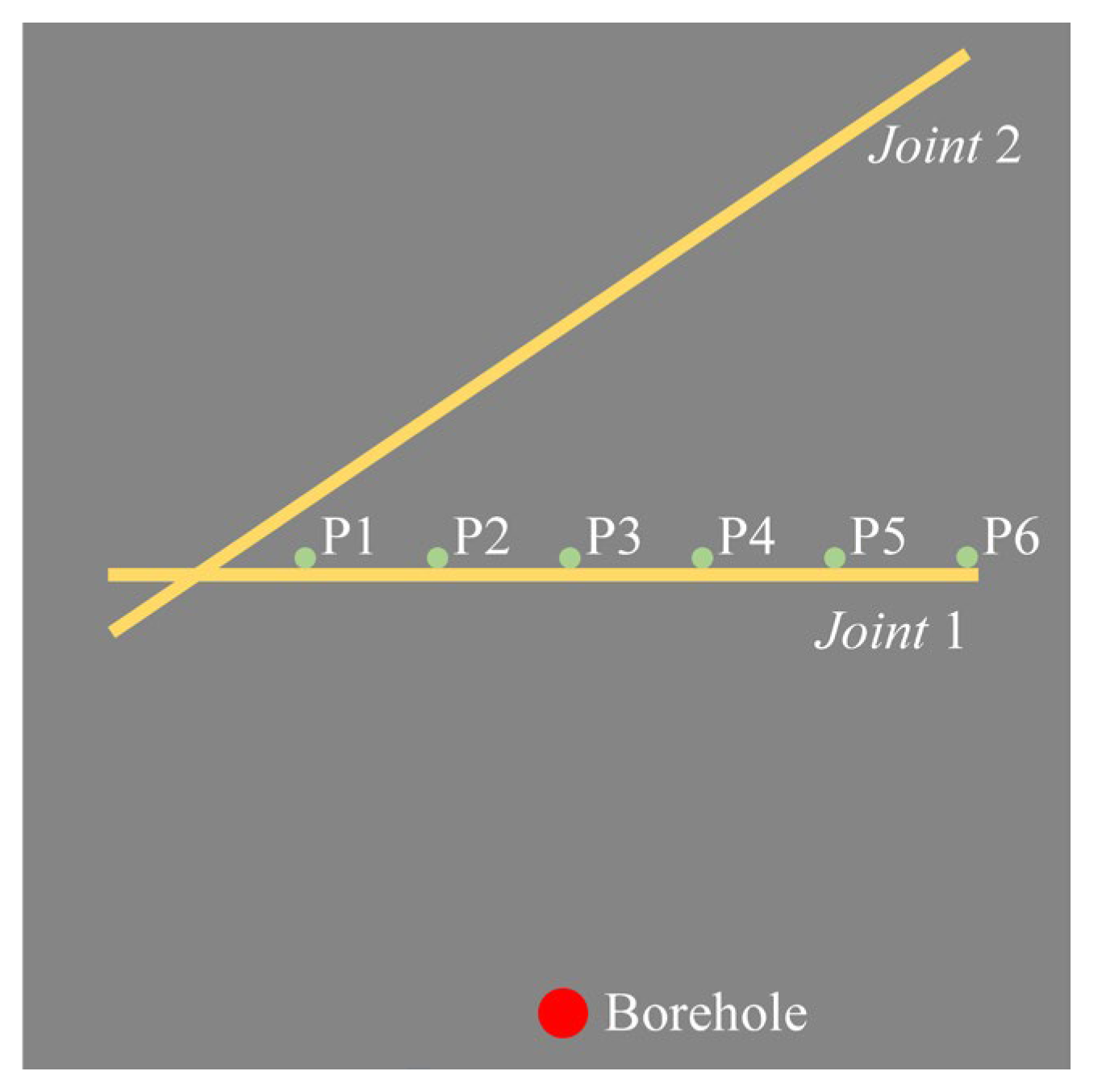
To further analyze crack propagation between the intersecting joints, six monitoring points were placed along the far side of J1 at 10 cm intervals, as illustrated in Figure 5. The stress evolution induced by blasting was recorded at these points to characterize the interaction between the joints.
Figure 5.
Schematic diagram of monitoring point arrangement.
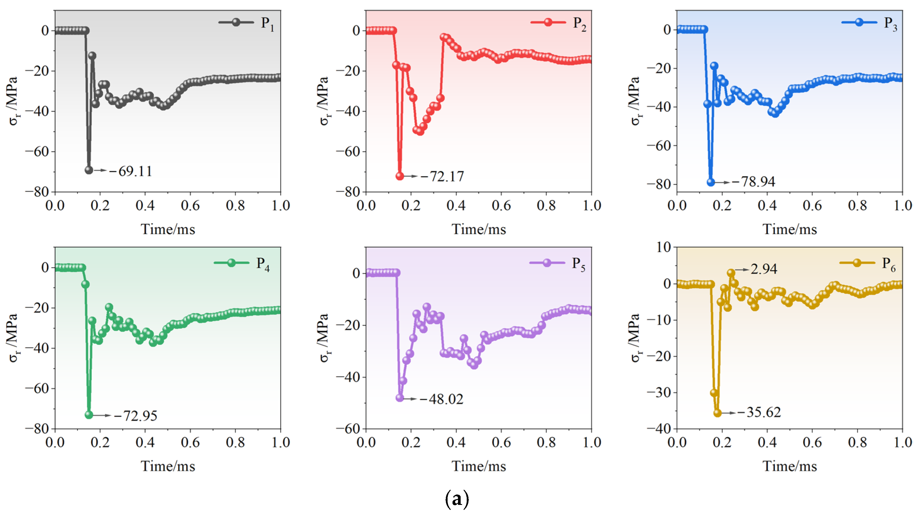
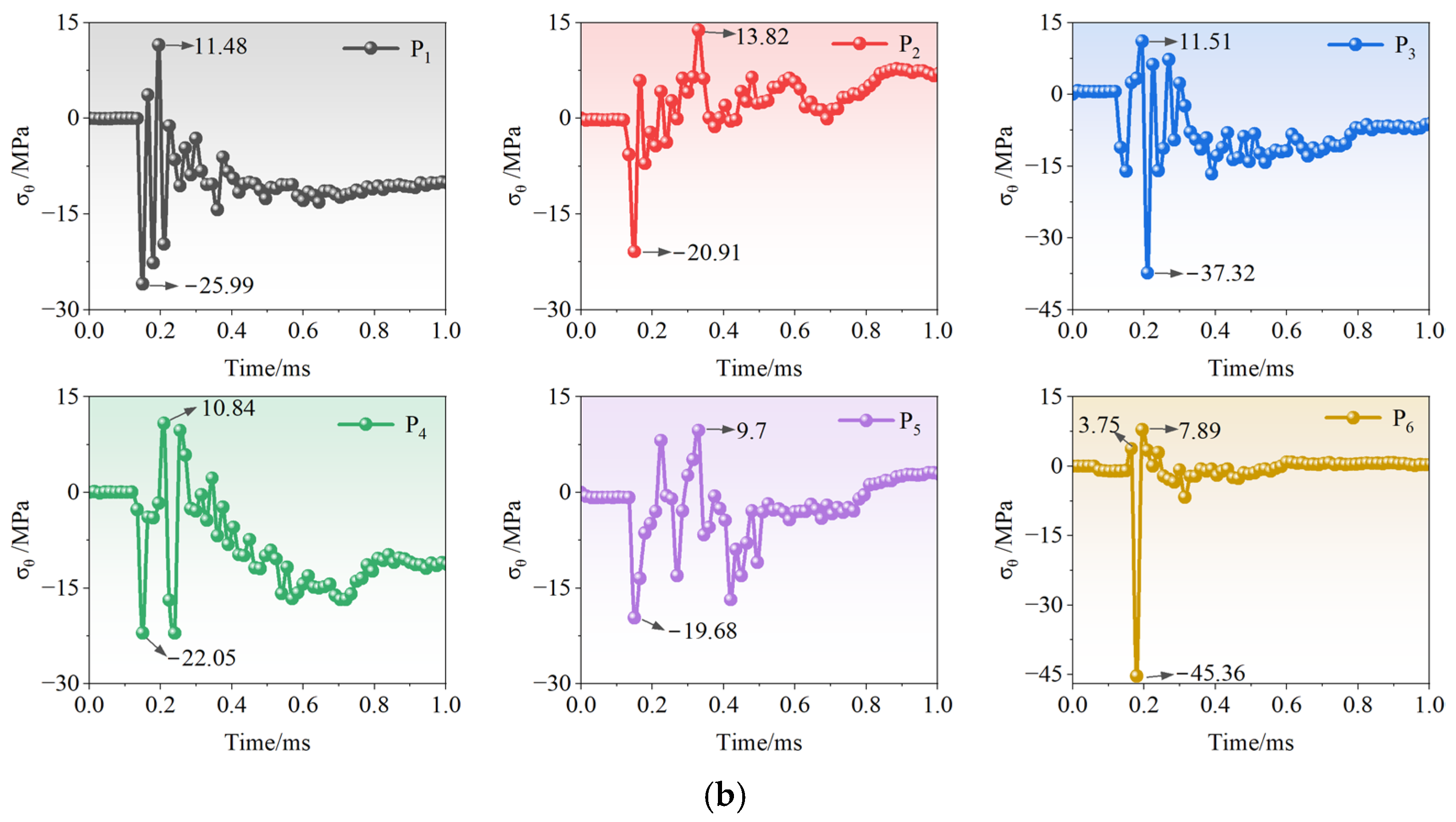
Figure 6 illustrates the temporal evolution of radial and circumferential stresses at the monitoring points, where tensile stress is defined as positive and compressive stress as negative. Overall, the radial stress remains predominantly compressive, whereas the circumferential stress alternates between compression and tension.

Figure 6.
Variation in radial and circumferential stresses at monitoring points: (a) Radial; (b) Circumferential.
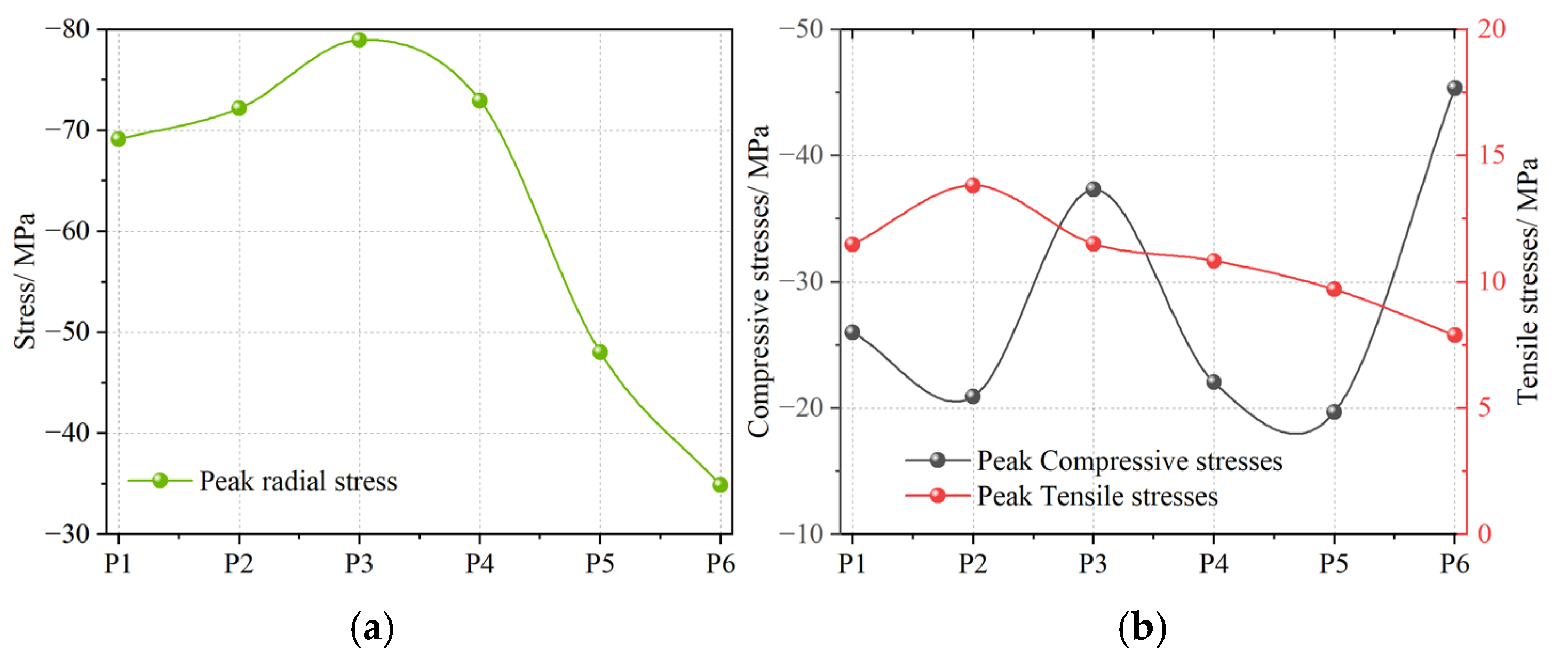
As shown in Figure 6a, the radial stress curves display similar temporal patterns across all monitoring points. At approximately 120 μs, the incident wave reaches J1, producing a sharp stress increase followed by attenuation after the peak. The corresponding peak radial compressive stresses are plotted in Figure 7a, showing a single-peak distribution with the central point (point 3) experiencing the maximum stress. The peak stresses at neighboring points gradually decrease as the incident angle of the explosive stress wave diminishes relative to the joint plane.
Figure 7.
Peak stress curves at different monitoring points. (a) Radial; (b) Circumferential.
In contrast, the circumferential stress curves exhibit pronounced oscillations. For example, at point 5, the stress rises sharply to −19.68 MPa at 150 μs, then decreases to approximately −4.89 MPa. Subsequently, the circumferential stress reverses to tension, reaching a peak of 8.13 MPa, followed by three additional compression–tension cycles, which are also observed at other monitoring points. This behavior indicates that the transmitted wave within J1 undergoes repeated reflections between the intersecting joints, producing alternating tensile stresses that promote fracture development. At the joint tip (point 6), however, the stress evolution differs: the circumferential stress is initially tensile, then rapidly drops into compression and peaks at −45.36 MPa. This phenomenon arises from stress wave diffraction at the joint tip, where the diffracted tensile component is subsequently reinforced by the transmitted wave.
Figure 7b presents the peak circumferential stresses. Unlike the radial stress distribution, the circumferential compressive stress exhibits a double-peak profile, with abrupt changes at the joint tips. The tensile stress, in contrast, decreases progressively with distance from the joint intersection: points near the intersection experience higher tensile peaks due to stronger and more frequent reflections, while points farther away show reduced tensile amplitudes.
3.2. Effect of Joint Angle on Stress Wave Propagation
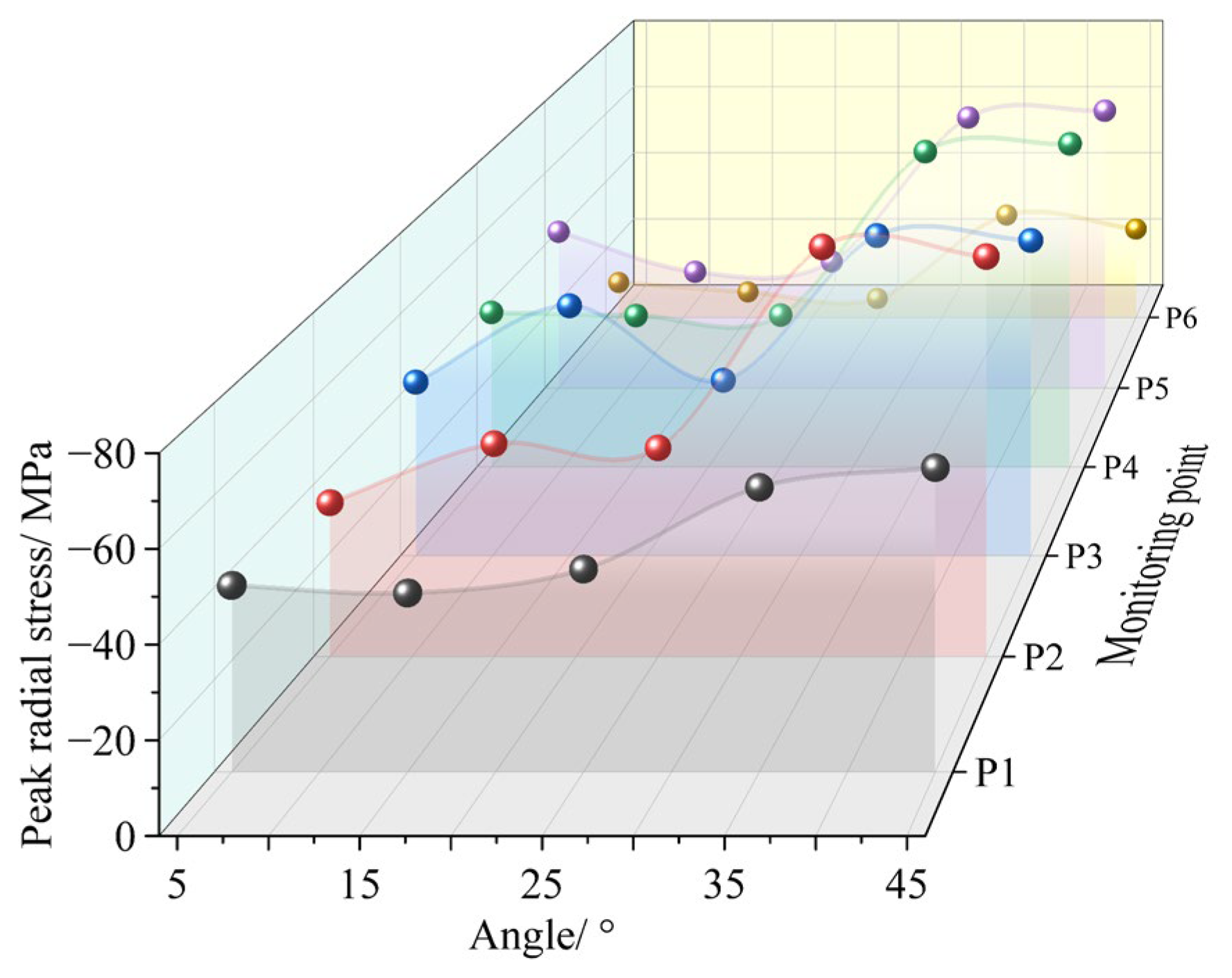
As noted above, the first radial stress peak at the monitoring points arises from the transmitted wave generated when the explosive stress wave impinges on the joint. Because the borehole–J1 distance remains constant, the first peak stress at each point is nearly identical across different joint angles when the joint thickness is fixed. To isolate the effect of joint angle on stress wave propagation, the joint thickness was therefore held constant at 0.2 r, minimizing the influence of infill thickness. For analysis, the second radial stress peak and the maximum circumferential stress at each monitoring point were extracted.
Figure 8 presents the peak radial stress distributions at the monitoring points. The results show that peak radial stress increases with joint angle. For angles below 25°, the variation in radial stress is relatively modest; however, when the angle exceeds 25°, the radial stress rises sharply, with the most pronounced increase observed at 35°, where the highest stress peaks occur. This trend is attributed to stress wave reflections between the joints. At small joint angles, stronger reflected stresses suppress the growth of radial compressive stress. With increasing angle, the restraining effect of reflections weakens, allowing larger radial stress peaks to develop.
Figure 8.
Peak radial stresses at monitoring points.
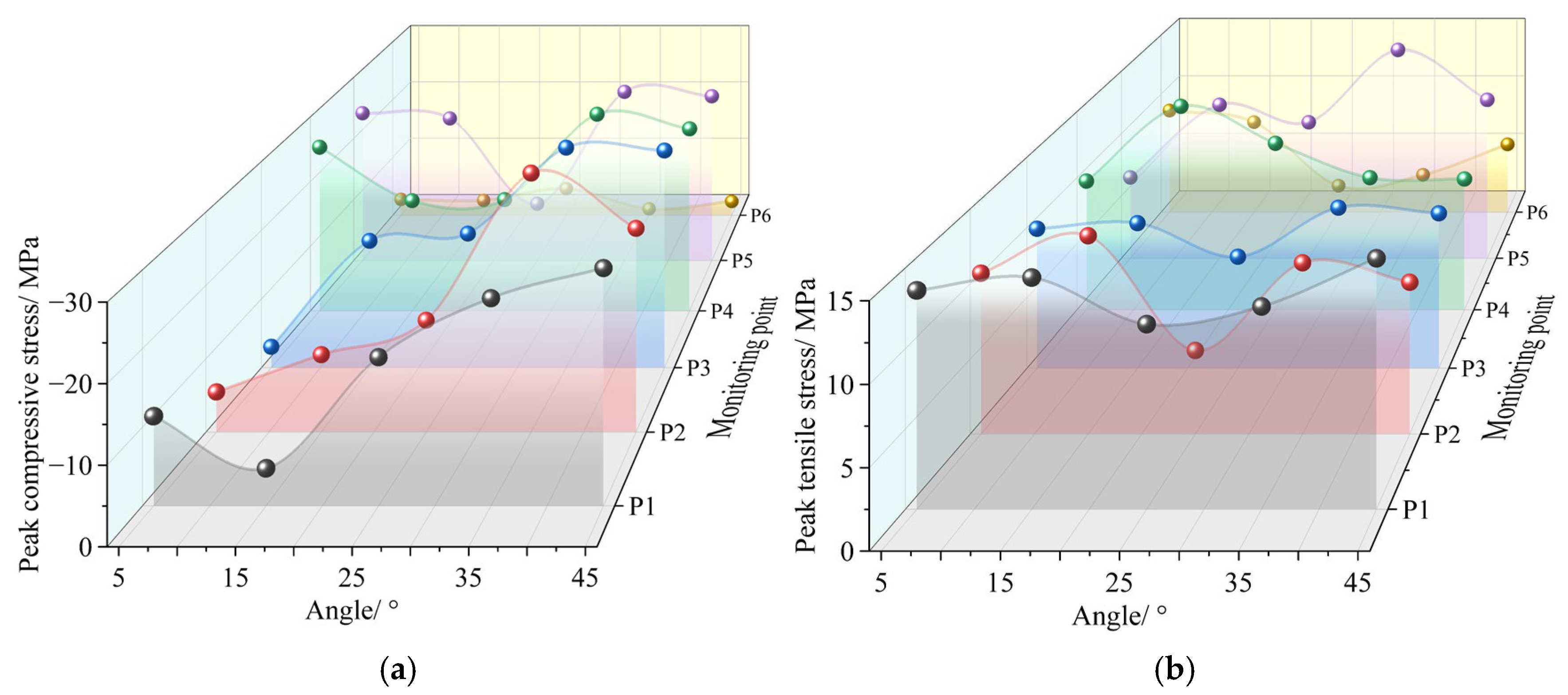
The peak circumferential compressive and tensile stresses are presented in Figure 9. Similar to the radial stress, the circumferential compressive stress increases with joint angle. In contrast, the circumferential tensile stress decreases as the joint angle increases. This trend can be explained by stress wave reflections between the intersecting joints: at smaller joint angles, stronger reflections generate higher tensile stresses while simultaneously suppressing compressive stress growth. As the joint angle increases, the reflection effect weakens, leading to progressively lower circumferential tensile stress peaks and enhanced compressive stress development.
Figure 9.
Peak circumferential stresses at monitoring points: (a) Compressive; (b) Tensile.
3.3. Effect of Joint Thickness on Stress Wave Propagation
As discussed above, the interaction between the intersecting joints is strongest at a joint angle of 35°. To examine the effect of joint infill thickness on stress wave propagation, the case with a 35° joint angle was analyzed. Peak radial and circumferential stresses at each monitoring point were extracted, as shown in Figure 10.
Figure 10.
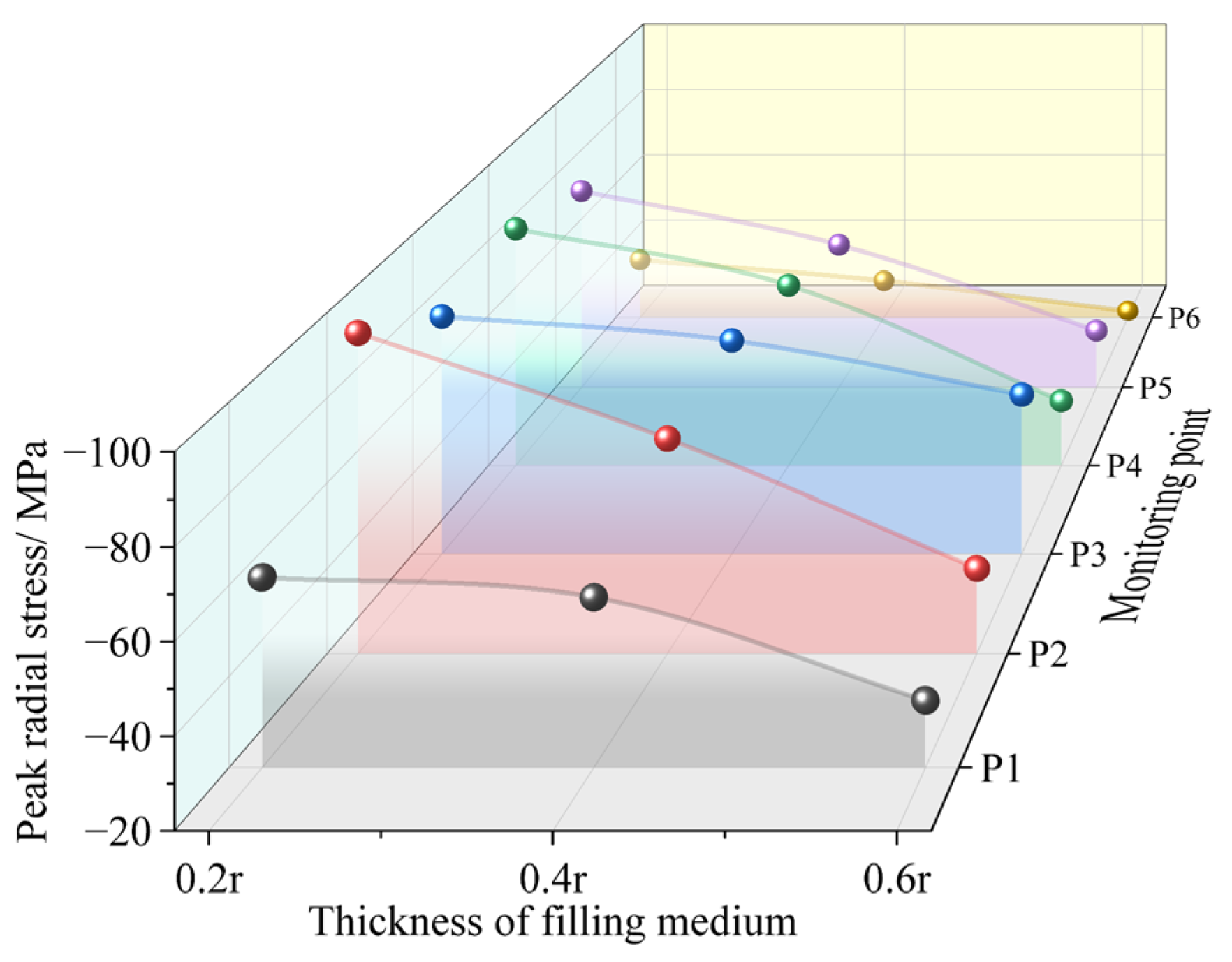
Peak radial stresses at monitoring points.
The results indicate that, as the joint thickness increases, the peak radial stress at all monitoring points decreases, with the most rapid reduction observed at 0.4 r. This trend is attributed to the reduced stiffness of thicker joints, which causes stress waves to undergo multiple successive reflections within the infill, dissipating energy and thereby diminishing the transmitted wave intensity.
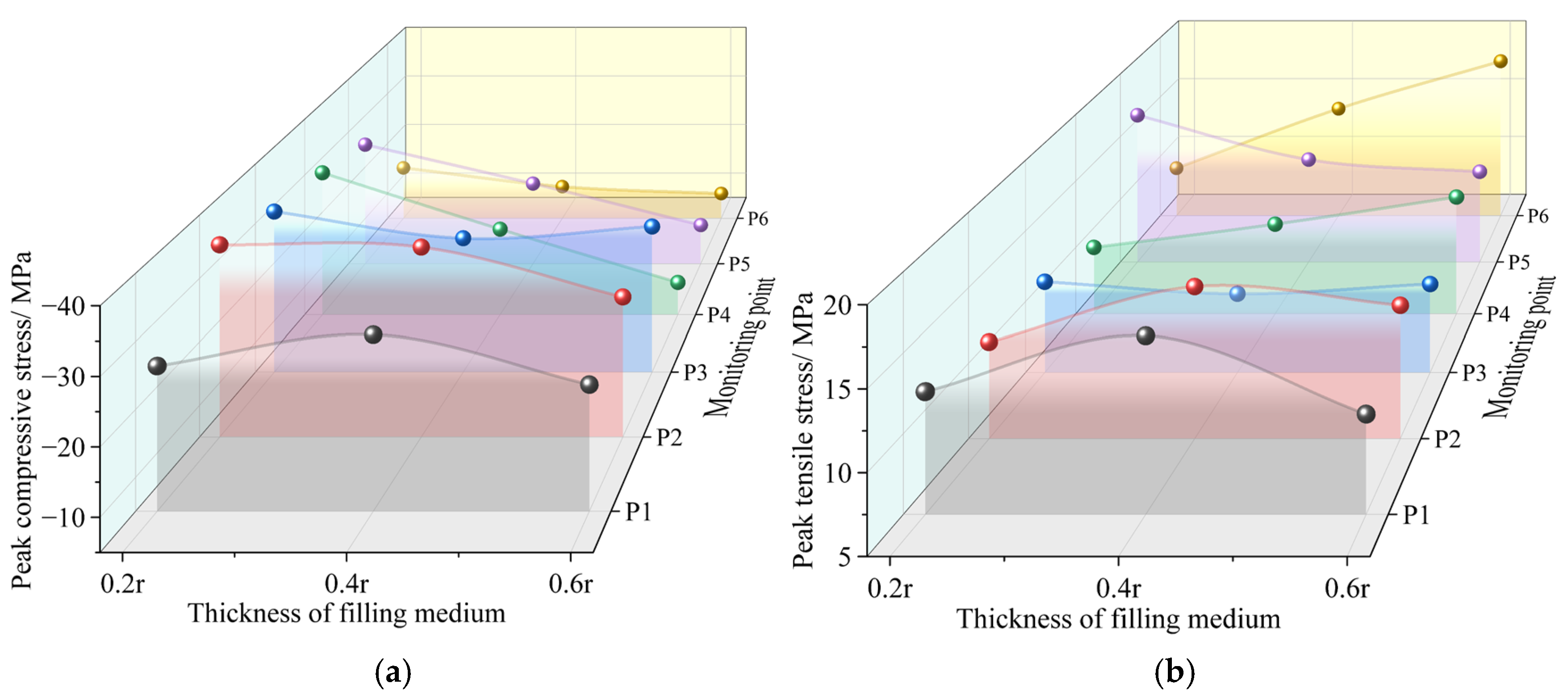
The peak circumferential stress distributions are shown in Figure 11. The circumferential compressive stress exhibits a trend similar to that of the radial stress, decreasing with increasing joint thickness. In contrast, the circumferential tensile stress shows a nonlinear response. At monitoring points P1–P5, the peak tensile stress gradually decreases as the joint thickness increases. However, at the joint ends, the circumferential tensile stress increases with increasing thickness, indicating that thicker joints induce stronger stress concentration at the tips and promote greater energy accumulation.
Figure 11.
Peak circumferential stresses at monitoring points: (a) Compressive; (b) Tensile.
Based on the above analysis, the stress distribution near the joint tip is significantly affected by the joint characteristics. To further quantify the influence of joint angle and thickness on the peak stress, monitoring point P6 was selected as the reference, with α = 5° and D = 0.2 r as the baseline conditions. The variations in radial and circumferential peak stresses under different joint angles and thicknesses were evaluated in terms of percentage increase or decrease relative to the reference case, as summarized in Table 4.
Table 4.
Percentage changes in peak radial and circumferential stresses with varying joint angles and thicknesses.
4. Analysis of Blasting-Induced Crack Propagation in Jointed Rock Mass
4.1. Crack Propagation in Jointed Rock Under Blasting with Varying Joint Characteristics
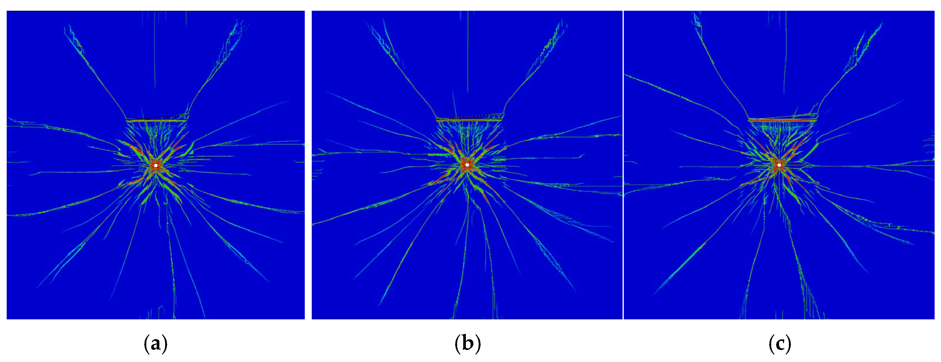
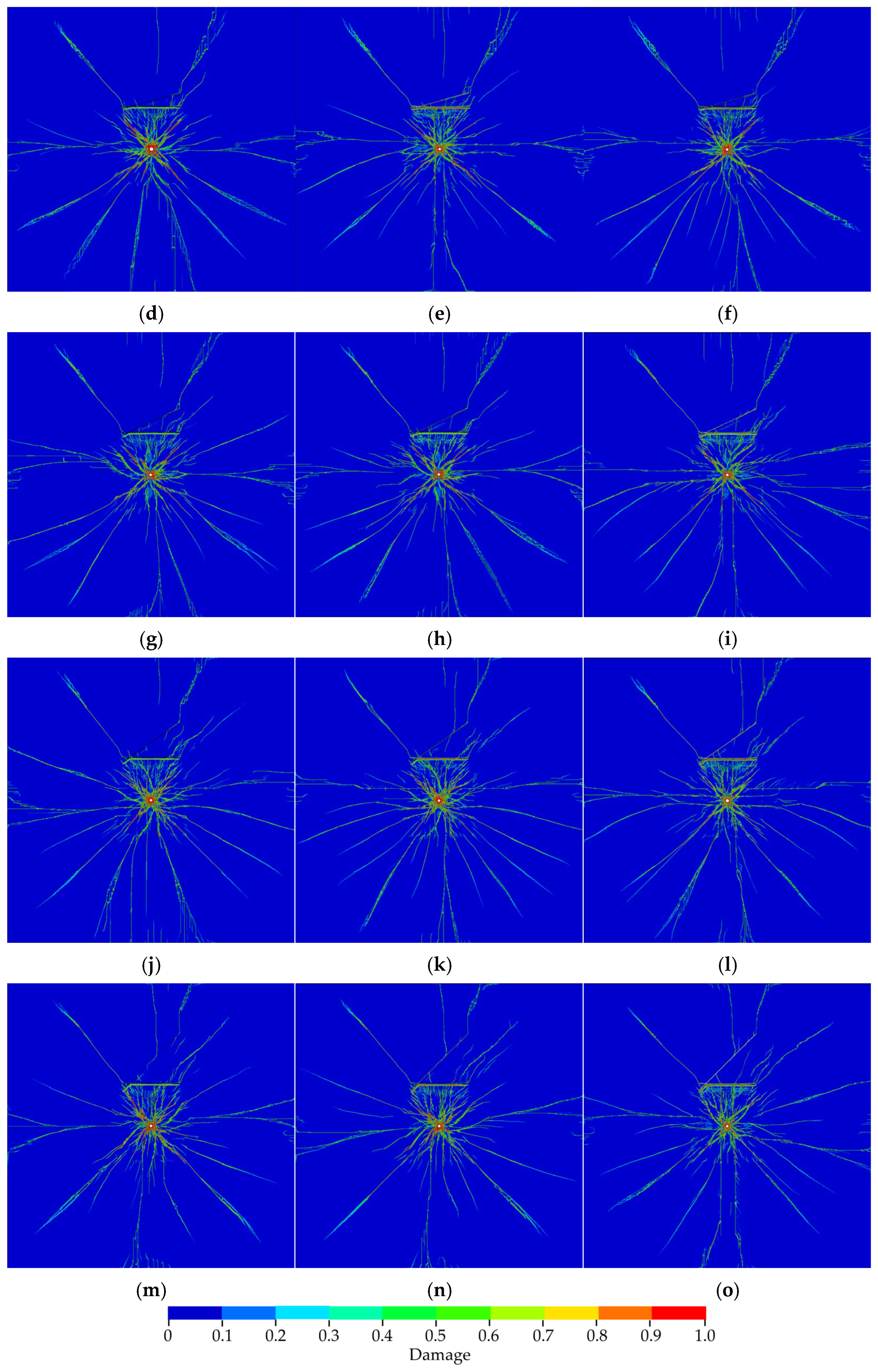
Figure 12 illustrates the crack propagation patterns in jointed rock under blasting for varying joint characteristics. Blasting-induced cracks generally comprise radial main cracks along the borehole, wing cracks at joint ends, and inter-joint cracks, with the propagation behavior strongly influenced by joint properties.

Figure 12.
Crack Propagation Patterns in Intersecting-joint under Blasting with Different Joint Characteristics. (a) α = 5°, D = 0.2 r; (b) α = 5°, D = 0.4 r; (c) α = 5°, D = 0.6 r; (d) α = 15°, D = 0.2 r; (e) α = 15°, D = 0.4 r; (f) α = 15°, D = 0.6 r; (g) α = 25°, D = 0.2 r; (h) α = 25°, D = 0.4 r; (i) α = 25°, D = 0.6 r; (j) α = 35°, D = 0.2 r; (k) α = 35°, D = 0.4 r; (l) α = 35°, D = 0.6 r; (m) α = 45°, D = 0.2 r; (n) α = 45°, D = 0.4 r; (o) α = 45°, D = 0.6 r.
For a fixed joint angle, when the joint thickness is 0.2 r, the radial main cracks between the borehole and the joint are distributed radially, resembling the crack pattern observed in joint-free regions beneath the borehole. As D increases, the front face of J1 exhibits denser cracks, forming an inverted triangular distribution between the borehole and J1, while the main cracks in other directions diminish. Additionally, increasing the joint angle amplifies the concentration of cracks between the borehole and the horizontal joint. These observations indicate that both joint thickness and joint angle jointly affect the crack propagation mode, primarily through changes in the intensity and number of reflected waves, which modify the principal stress field and thereby influence the direction and length of the main cracks.
Specifically, joint thickness predominantly governs the density of cracks on the front face of horizontal joints, whereas joint angle has multiple effects. At 5°, radial main cracks extend radially from the borehole before propagating horizontally, suggesting that the joint angle mainly alters crack orientation. For angles between 15° and 35°, the main cracks still radiate from the borehole but terminate after a finite distance. In this case, the inclined joint not only biases the crack propagation direction but also inhibits crack tip growth by reducing the propagation velocity. At 45°, both the biasing and inhibitory effects of the inclined joint are weakened.
Within the rock mass between joints, increasing D leads to crack concentration near the joint ends and a higher number of cracks at the joint tips. This is because thicker joints reduce stiffness, attenuate transmitted wave intensity, and weaken stress wave reflections, resulting in fewer inter-joint cracks, consistent with the previously discussed stress wave propagation characteristics. For inclined joints, larger joint angles facilitate the initiation and extension of wing cracks at the tips, and a main crack develops on the rear face of J2, with a propagation depth comparable to that of the wing cracks.
4.2. Statistical Analysis of Blasting-Induced Crack Distribution in Rock Mass
The spatial distribution of blasting-induced cracks in rock mass serves as a crucial indicator for assessing rock damage, and proper control of crack propagation can mitigate over- or under-excavation. Previous studies [] have demonstrated that the evolution of blasting-induced cracks exhibits fractal characteristics. To quantitatively describe the crack distribution in intersecting-joint rock under blasting, the fractal dimension is employed. Several approaches exist to calculate the fractal dimension, including the self-similarity dimension, capacity dimension, multifractal dimension, and box-counting dimension. Among these, the box-counting dimension is widely adopted in crack studies due to its intuitive representation of spatial crack distribution and its computational simplicity. The box-counting dimension Df is defined as follows []:
In the equation, N(δk) represents the number of boxes containing crack information, and δk denotes the box size.
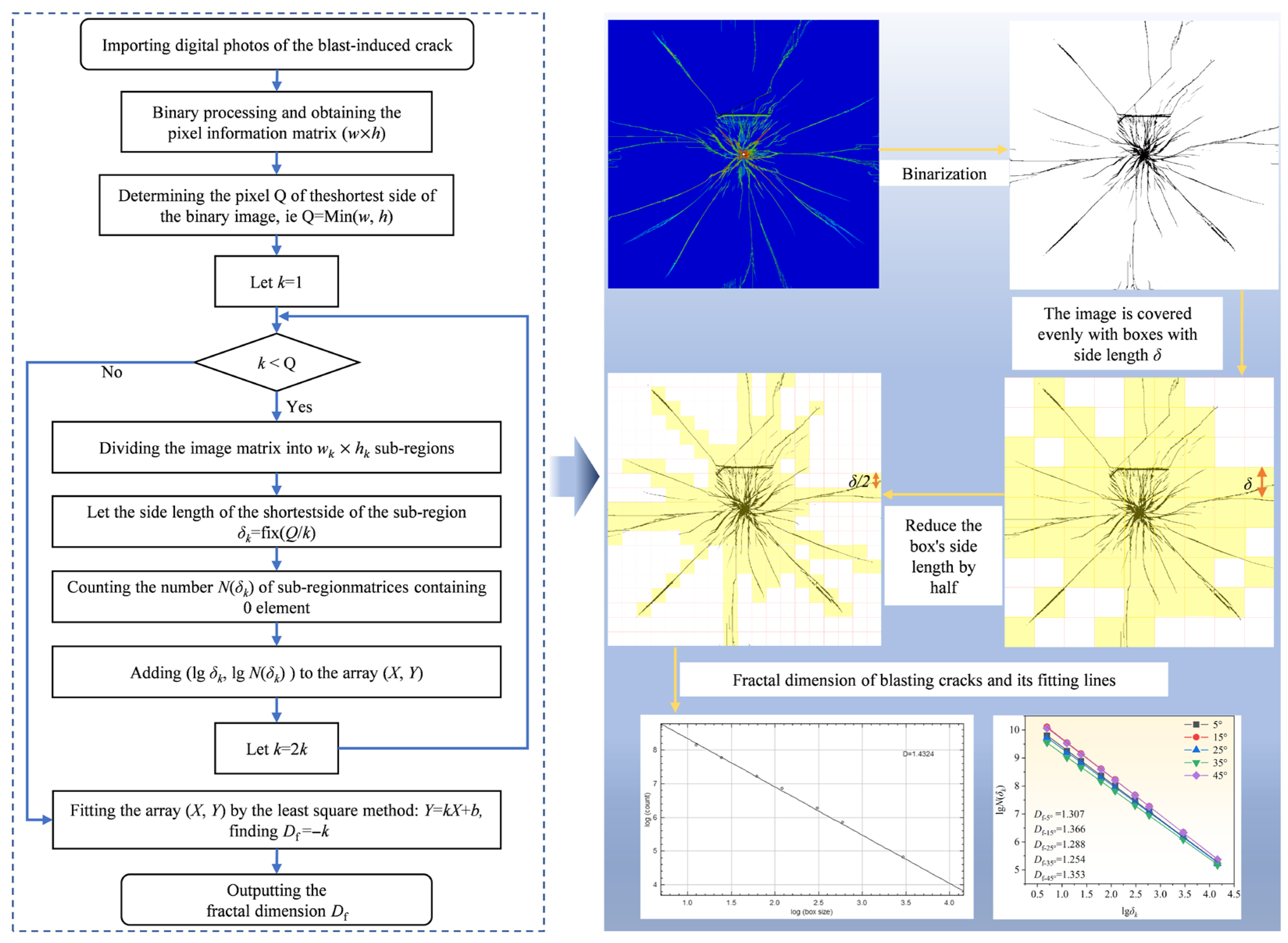
The box-counting fractal dimension method was employed to quantitatively characterize the complexity of blasting-induced cracks. Binary images of the cracks were processed and analyzed in MATLAB 2023b, where the images were partitioned and the fractal dimensions were subsequently calculated. The detailed computational procedure is illustrated in Figure 13.
Figure 13.
Procedure for calculating the fractal dimension of blasting-induced cracks by MATLAB.
In rock blasting, the fractal dimension can be employed to characterize the extent of rock damage, providing a unified description of both microcrack evolution and macroscopic damage features, while enabling quantitative analysis of internal damage progression under blasting loads. Accordingly, the relationship between the post-blast rock damage degree ω and the fractal dimension Df can be expressed as follows []:
In the equation, D0 denotes the fractal dimension of internal cracks before blasting, and represents the fractal dimension when the medium is completely damaged ( = 2 for two-dimensional problems and = 3 for three-dimensional problems). As indicated by Equation (6), a larger fractal dimension corresponds to more developed macroscopic cracks and a higher degree of rock damage.
4.3. Crack Distribution in Blasted Rock Mass with Varying Joint Configurations
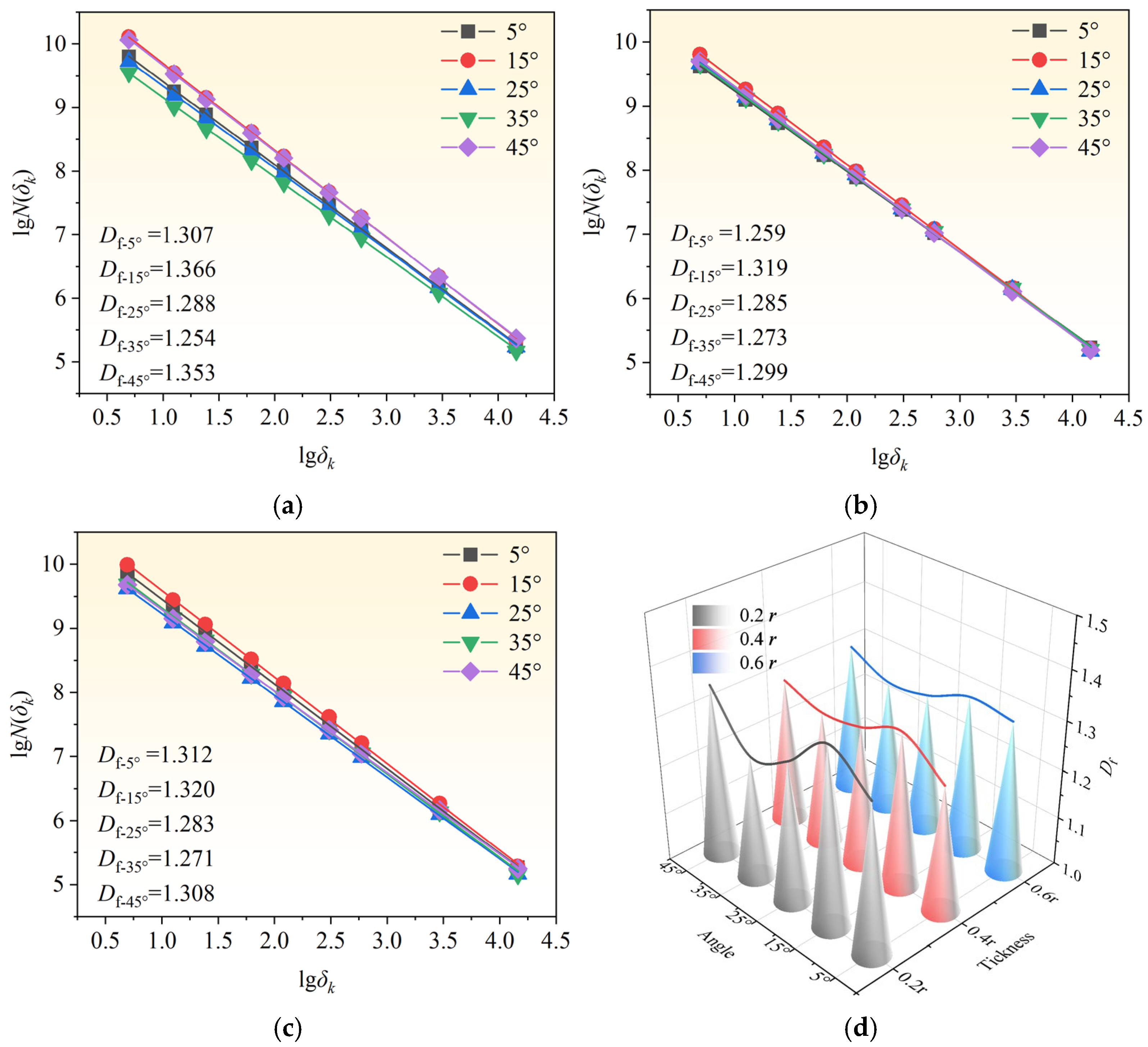
Using the fractal dimension calculation procedure illustrated in Figure 13, the fractal dimensions of blasting-induced cracks in rock mass with varying joint characteristics were statistically analyzed. The box-counting fitting lines are presented in Figure 14. The coefficient of determination (R2) for all 15 datasets exceeds 0.99, confirming that the propagation of blasting-induced cracks follows fractal scaling laws.
Figure 14.
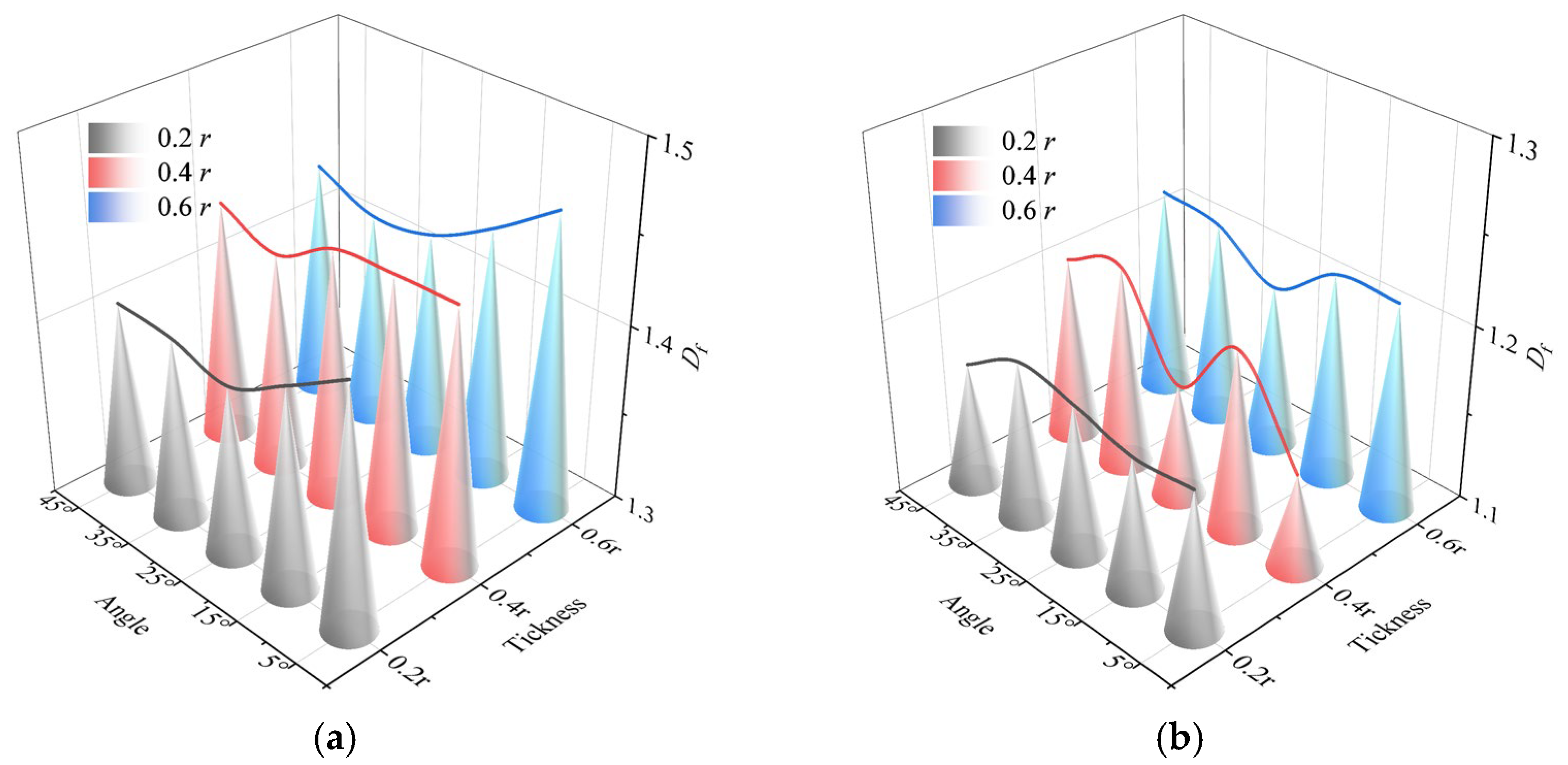
Calculation curves of box-counting dimension. (a) D = 0.2 r; (b) D = 0.4 r; (c) D = 0.6 r; (d) fractal dimension curve.
As shown in Figure 14, the fractal dimension exhibits a non-monotonic trend with increasing joint thickness, initially decreasing and then increasing. When the joint thickness is relatively small (D = 0.2 r), the cracks display relatively high fractal dimensions. Regarding joint angle, the fractal dimensions of blasting-induced cracks decrease in the order of 15°, 45°, 5°, 25°, and 35°, corresponding to ω of 0.683, 0.676, 0.653, 0.644, and 0.627, respectively. This indicates that neither the fractal dimension nor the rock damage degree increases monotonically with joint angle. The repeated reflection of stress waves between joints plays a crucial role in controlling the propagation of blasting-induced cracks.
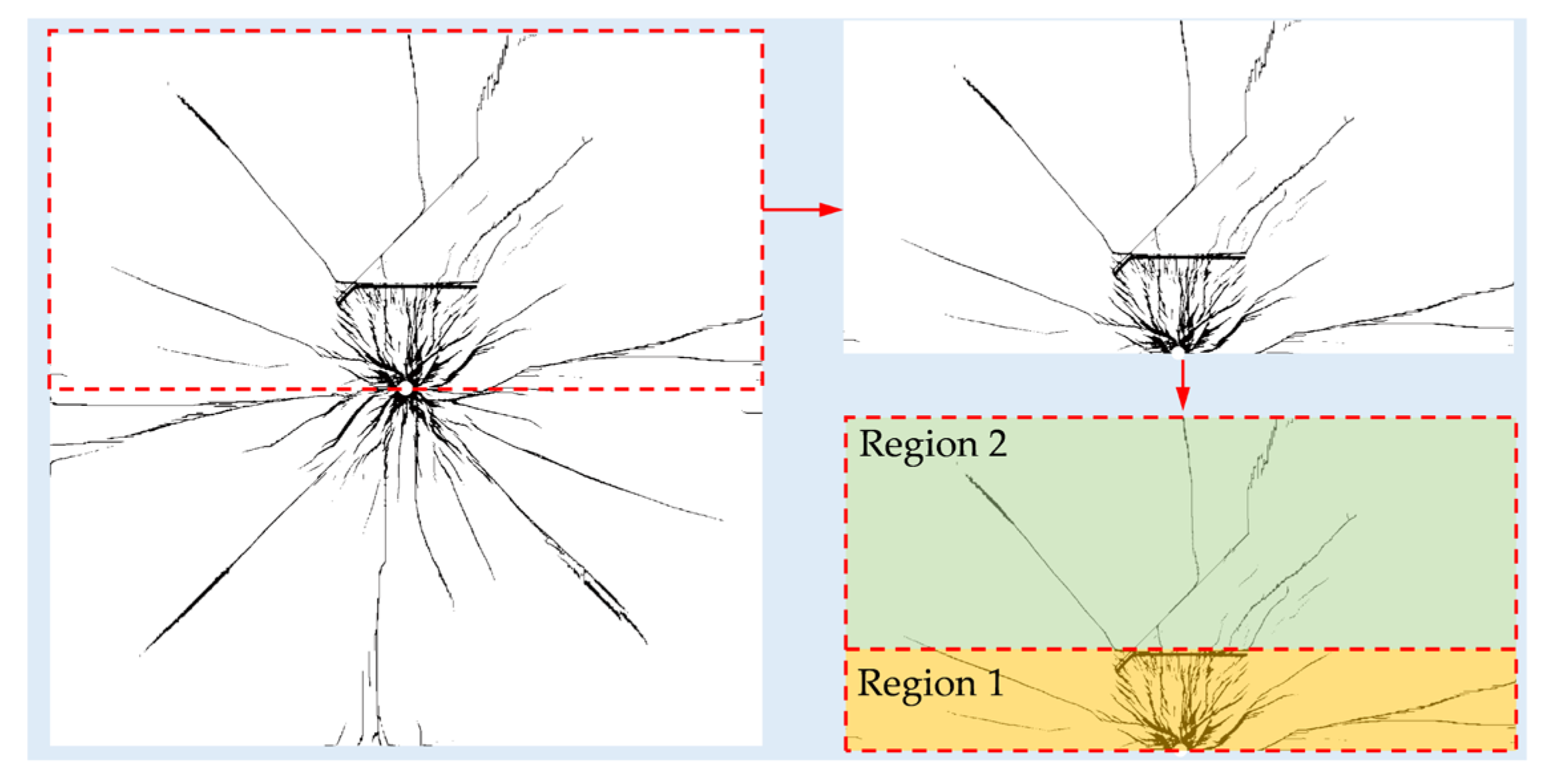
To specifically investigate the influence of different joint characteristics on the distribution of blasting-induced cracks in rock mass, the cracks along the borehole axis were extracted. The cracked zone along the horizontal joint J1 was divided into two regions for analysis: Region 1 (R1) and Region 2 (R2), as illustrated in Figure 15. R1 corresponds to the rock mass between the borehole and J1, while R2 corresponds to the rock mass above J1.
Figure 15.
Division of blasting-induced cracks into distinct regions.
The fractal dimension curves of blasting-induced cracks in R1 and R2 under varying joint characteristics are presented in Figure 16. It is evident that the fractal dimensions in R1 are generally higher than those in R2, indicating more developed cracks and greater rock damage between the borehole and the horizontal joint. With increasing joint angle, the fractal dimension in R1 initially decreases and then increases. Specifically, for joint angles between 15° and 35°, the fractal dimension is relatively low. This trend aligns with the stress analysis results, as larger joint angles correspond to higher radial and circumferential compressive stress peaks, which enhance both the deflection and inhibition of main cracks.
Figure 16.
Fractal dimension curves of blast-induced cracks in distinct regions. (a) R1; (b) R2.
For R2, when the joint angle is 5° or 15°, the fractal dimensions of blasting-induced cracks are similar, suggesting that the joint angle has a minor effect in this region. However, for joint angles exceeding 15°, the fractal dimensions in R2 increase due to longer propagation of inter-joint cracks and wing cracks at the ends of inclined joints. As joint thickness increases, the fractal dimensions in both R1 and R2 exhibit an increasing trend, although the underlying mechanisms differ. In R1, the increase is attributed to enhanced reflection of stress waves along the joint plane, intensifying tensile–shear damage on the blast-facing side. In R2, the increase results from stronger diffraction of stress waves at the joint ends, causing persistent stress concentration and greater energy accumulation, which promotes more extensive crack development.
The above results indicate that variations in joint thickness and angle alter the transmission and reflection mechanisms of stress waves along the joint planes, thereby modifying the principal stress field and leading to distinct patterns of blasting-induced crack propagation. The final crack morphology of the rock mass demonstrates that joint thickness primarily influences the density of cracks on the blast-facing side of horizontal joints, whereas joint angle exerts both deflecting and inhibiting effects on crack propagation.
Overall, the crack propagation pattern in rock masses with intersecting joints is more complex than that in rock masses with single or parallel joints. From a practical engineering perspective, when intersecting joints exist in the tunnel surrounding rock, peripheral hole blasting may induce extensive lateral crack development at the tips of oblique joints. Adjacent cracks tend to coalesce, which may lead to local block instability as well as significant overbreak or underbreak. Therefore, to achieve an ideal excavation profile, blasting design and drilling operations should, whenever possible, avoid intersecting joints or arrange blastholes at the intersections of joints. If drilling near joints is unavoidable, the hole spacing and the charge per hole should be appropriately reduced.
5. Conclusions
In this study, the explicit dynamic finite element method was employed and the RHT model was used to simulate the blasting process of rock mass with varying joint characteristics. The propagation of explosive stress waves and crack development in jointed rock were analyzed. Furthermore, based on fractal theory, the spatial distribution of blasting-induced cracks was quantitatively evaluated using MATLAB, and the influence of joint characteristics on crack propagation patterns was investigated. The main conclusions are summarized as follows:
(1) Joint thickness influences the transmission and reflection mechanisms of stress waves along the joint planes. As the joint thickness increases, reflection becomes stronger and reflected waves are more intense; however, due to successive reflections within the joint infill, energy is dissipated and transmitted waves experience greater attenuation. Joint angle affects the number of reflections between joints. Smaller joint angles lead to stronger interactions between joints, manifested as reduced radial and circumferential compressive stress peaks and increased circumferential tensile stress peaks.
(2) Joint thickness and angle jointly affect the propagation mode of blasting-induced cracks. Cracks tend to concentrate between the borehole and the joints, forming a roughly triangular distribution. The joint thickness primarily determines the density of cracks on the blast-facing side of horizontal joints, with thicker joints resulting in more developed cracks. Joint angle exerts both deflecting and inhibiting effects on crack propagation, causing the radial main cracks to shift from a radial to a more horizontal direction. When the joint angle ranges from 15° to 35°, the propagation of main cracks is significantly suppressed.
(3) The fractal dimension of blasting-induced cracks varies nonlinearly with joint thickness and angle. In the region above the horizontal joint, the fractal dimension is lower than that between the borehole and the horizontal joint. However, as joint thickness and angle increase, the fractal dimension in this region exhibits trends distinct from the borehole-to-joint region and shows a positive correlation with both joint thickness and angle.
To minimize overbreak or underbreak, boreholes should be positioned to avoid intersecting joints whenever possible or placed at joint intersections with appropriately reduced spacing. The findings provide experimental references and theoretical guidance for engineers in the design and implementation of blasting in jointed rock mass.
Author Contributions
Conceptualization, X.Y. and Y.W.; Data curation, X.Z.; Formal analysis, X.Y., Y.W., X.Z. and Z.L.; Funding acquisition, X.Z.; Methodology, F.W.; Resources, Y.Z.; Supervision, Z.L.; Writing—original draft, X.Y. and Y.W.; Writing—review and editing, W.G. and F.W. All authors have read and agreed to the published version of the manuscript.
Funding
The research work of this paper was funded by Beijing Postdoctoral Research Foundation (2022- ZZ-100).
Data Availability Statement
The data presented in this study are available on request from the corresponding author.
Conflicts of Interest
Authors Feng Wang and Yang Zhang were employed by the company Beijing CAS-Mechanics Blasting Co., Ltd. The remaining authors declare that the research was conducted in the absence of any commercial or financial relationships that could be construed as a potential conflict of interest.
References
- Silva, J.; Worsey, T.; Lusk, B. Practical Assessment of Rock Damage due to Blasting. Int. J. Min. Sci. Technol. 2019, 29, 379–385. [Google Scholar] [CrossRef]
- Li, Z.; Zhang, X.; Zhu, Z.; Wu, Y.; Yu, H.; Gao, W.; Lv, B. Detonation Dynamics and Damage Behavior of Segmented Tunnel Charges with Shaped Liners. Buildings 2025, 15, 2815. [Google Scholar] [CrossRef]
- Dotto, M.S.; Pourrahimian, Y. The Effect of Initiation Time Delay and Sequencing on Rock Damage in Multi-Hole Blasting. Mining 2025, 5, 22. [Google Scholar] [CrossRef]
- Wu, Y.; Zhang, X.; Li, Z.; Gao, W.; Xu, Z.; Zhang, Y.; Zhou, J. Effects of In-Situ Stress on Damage and Fractal during Cutting Blasting Excavation. Fractal Fract. 2024, 8, 450. [Google Scholar] [CrossRef]
- Li, J.; Ma, G.; Huang, X. Analysis of Wave Propagation through a Filled Rock Joint. Rock Mech. Rock Eng. 2010, 43, 789–798. [Google Scholar] [CrossRef]
- Li, F.; Yang, G.; Guo, D.; Liu, X.; Wang, X.; Hu, G. Toward Sustainable Geohazard Assessment: Dynamic Response and Failure Characteristics of Layered Rock Slopes under Earthquakes via DEM Simulations. Sustainability 2025, 17, 7374. [Google Scholar] [CrossRef]
- Luo, Z.; Gao, Z.; Liu, G.; Du, C.; Liu, W.; Wang, Z. Research on the Damage Mechanism and Shear Strength Weakening Law of Rock Discontinuities under Dynamic Load Disturbance. Symmetry 2025, 17, 569. [Google Scholar] [CrossRef]
- Jiang, X.; Xue, Y.; Kong, F.; Gong, H.; Fu, Y.; Zhang, W. Dynamic Responses and Damage Mechanism of Rock with Discontinuity Subjected to Confining Stresses and Blasting Loads. Int. J. Impact Eng. 2023, 172, 104404. [Google Scholar] [CrossRef]
- Liang, X.; Ding, C.; Zhu, X.; Zhou, J.; Chen, C.; Guo, X. Visualization Study on Stress Evolution and Crack Propagation of Jointed Rock Mass under Blasting Load. Eng. Fract. Mech. 2024, 296, 109833. [Google Scholar] [CrossRef]
- Shen, Y.; Lin, B.; Lin, M.; Liu, T.; Zhang, X.; Yang, W.; Zhang, C. Experiments and Discrete Element Simulations on the Influence of Symmetrical Forms of Joints on the Propagation of Blasting Cracks. Eng. Fract. Mech. 2025, 320, 111072. [Google Scholar] [CrossRef]
- Xu, P.; Yang, R.; Guo, Y.; Guo, Z. Investigation of the Blasting-induced Crack Propagation Behavior in a Material Containing an Unfilled Joint. Appl. Sci. 2020, 10, 4419. [Google Scholar] [CrossRef]
- Li, J.; Ma, G. Analysis of Blast Wave Interaction with a Rock Joint. Rock Mech. Rock Eng. 2010, 43, 777–787. [Google Scholar] [CrossRef]
- Li, J.C.; Wu, W.; Li, H.; Zhu, J.; Zhao, J. A Thin-Layer Interface Model for Wave Propagation through Filled Rock Joints. J. Appl. Geophys. 2013, 91, 31–38. [Google Scholar] [CrossRef]
- Li, J.; Li, H.; Jiao, Y.; Liu, Y.; Xia, X.; Yu, C. Analysis for Oblique Wave Propagation across Filled Joints Based on Thin-Layer Interface Model. J. Appl. Geophys. 2014, 102, 39–46. [Google Scholar] [CrossRef]
- Miller, R.K. An Approximate Method of Analysis of the Transmission of Elastic Waves through a Frictional Boundary. J. Appl. Math. 1977, 44, 652–656. [Google Scholar] [CrossRef]
- Schoenberg, M. Elastic Wave Behavior across Linear Slip Interfaces. J. Acoust. Soc. Am. 1980, 68, 1516–1521. [Google Scholar] [CrossRef]
- Desai, C.; Zaman, M.; Lightner, J.; Siriwardane, H. Thin-Layer Element for Interfaces and Joints. Int. J. Numer. Anal. Methods Geomech. 1984, 8, 19–43. [Google Scholar] [CrossRef]
- Duanying, W.; Zheming, Z.; Ruifeng, L.; Bang, L. Effect of Two Parallel Cracks on Main Propagating Cracks under Blasting. Explos. Shock. Waves 2019, 39, 083105. (In Chinese) [Google Scholar]
- Al-Yaari, A.; Ching, D.L.C.; Sakidin, H.; Muthuvalu, M.S.; Zafar, M.; Haruna, A.; Merican, Z.M.A.; Yunus, R.B.; Al-Dhawi, B.N.S.; Jagaba, A.H. The effects of nanofluid thermophysical properties on enhanced oil recovery in a heterogenous porous media. Case Stud. Chem. Environ. Eng. 2024, 9, 100556. [Google Scholar] [CrossRef]
- Zhai, J.; Wang, Z.; Wang, J.; Feng, C.; Li, S. Numerical Study on Blast Dynamic Response of Jointed Rock Mass under High Geostress Field. Int. J. Geomech. 2025, 25, 04025005. [Google Scholar] [CrossRef]
- Li, J.C. Wave Propagation across Non-Linear Rock Joints Based on Time-Domain Recursive Method. Geophys. J. Int. 2013, 193, 970–985. [Google Scholar] [CrossRef]
- Zhang, Q. The Transmission Process of Stress Waves at Joints. Chin. J. Geotech. Eng. 1986, 8, 99–105. (In Chinese) [Google Scholar]
- Johnson, G.R.; Holmquist, T.J. An Improved Computational Constitutive Model for Brittle Materials. In AIP Conference Proceedings; American Institute of Physics: College Park, MD, USA, 1994; Volume 309, pp. 981–984. [Google Scholar]
- Borrvall, T.; Riedel, W. The RHT Concrete Model in LS-DYNA. In Proceedings of the 8th European LS-DYNA User Conference, Strasbourg, France, 23–24 May 2011; pp. 23–24. [Google Scholar]
- Bornstein, H.; Kuznetsov, V.; Lu, J.-P.; Stojko, S.; Freundt, J. Characterisation and Validation of the JWL Equation of State Parameters for PE4. Int. J. Impact Eng. 2022, 164, 104190. [Google Scholar] [CrossRef]
- Yang, J.; Peng, C.; Ye, Z.; Yao, C.; Zhang, X.; Ma, Y.; Zhou, C. Study on the Efficiency of Energy Transfer in the Blasting with Different Coupling Mediums for Deep Rock Mass Excavation. Eng. Fract. Mech. 2025, 319, 111048. [Google Scholar] [CrossRef]
- Sharma, K.; Desai, C. Analysis and Implementation of Thin-Layer Element for Interfaces and Joints. J. Eng. Mech. 1992, 118, 2442–2462. [Google Scholar] [CrossRef]
- Wei, X.; Zhao, Z.; Gu, J. Numerical Simulations of Rock Mass Damage Induced by Underground Explosion. Int. J. Rock Mech. Min. Sci. 2009, 46, 1206–1213. [Google Scholar] [CrossRef]
- Xiao, C.; Yang, R.; Ma, X.; Wang, Y.; Ding, C. Damage Evaluation of Rock Blasting Based on Multi-Fractal Study. Int. J. Impact Eng. 2024, 188, 104953. [Google Scholar] [CrossRef]
- Li, K.; Cheng, Y.; Fan, X. Roles of Model Size and Particle Size Distribution on Macro-Mechanical Properties of Lac du Bonnet Granite Using Flat-Joint Model. Comput. Geotech. 2018, 103, 43–60. [Google Scholar] [CrossRef]
- Ding, C.; Yang, R.; Yang, L. Experimental Results of Blasting-induced Cracking Fractal Characteristics and Propagation Behavior in Deep Rock Mass. Int. J. Rock Mech. Min. Sci. 2021, 142, 104772. [Google Scholar] [CrossRef]
Disclaimer/Publisher’s Note: The statements, opinions and data contained in all publications are solely those of the individual author(s) and contributor(s) and not of MDPI and/or the editor(s). MDPI and/or the editor(s) disclaim responsibility for any injury to people or property resulting from any ideas, methods, instructions or products referred to in the content. |
© 2025 by the authors. Licensee MDPI, Basel, Switzerland. This article is an open access article distributed under the terms and conditions of the Creative Commons Attribution (CC BY) license (https://creativecommons.org/licenses/by/4.0/).