Article

An Enhanced Multiple Unmanned Aerial Vehicle Swarm Formation Control Using a Novel Fractional Swarming Strategy Approach

by
Abdul Wadood
1,2,*,
Al-Fahad Yousaf
3 and
Aadel Mohammed Alatwi
1,*
1
Renewable Energy and Environmental Technology Center, University of Tabuk, Tabuk 47913, Saudi Arabia
2
Electrical Engineering Department, Faculty of Engineering, University of Tabuk, Tabuk 47913, Saudi Arabia
3
Department of Electrical Engineering, Air University Islamabad, Aerospace and Aviation Campus, Attock 43570, Pakistan
*
Authors to whom correspondence should be addressed.
Fractal Fract. 2024, 8(6), 334; https://doi.org/10.3390/fractalfract8060334
Submission received: 30 April 2024 / Revised: 24 May 2024 / Accepted: 28 May 2024 / Published: 3 June 2024

Abstract

:
This paper addresses the enhancement of multiple Unmanned Aerial Vehicle (UAV) swarm formation control in challenging terrains through the novel fractional memetic computing approach known as fractional-order velocity-pausing particle swarm optimization (FO-VPPSO). Existing particle swarm optimization (PSO) algorithms often suffer from premature convergence and an imbalanced exploration–exploitation trade-off, which limits their effectiveness in complex optimization problems such as UAV swarm control in rugged terrains. To overcome these limitations, FO-VPPSO introduces an adaptive fractional order β and a velocity pausing mechanism, which collectively enhance the algorithm’s adaptability and robustness. This study leverages the advantages of a meta-heuristic computing approach; specifically, fractional-order velocity-pausing particle swarm optimization is utilized to optimize the flying path length, mitigate the mountain terrain costs, and prevent collisions within the UAV swarm. Leveraging fractional-order dynamics, the proposed hybrid algorithm exhibits accelerated convergence rates and improved solution optimality compared to traditional PSO methods. The methodology involves integrating terrain considerations and diverse UAV control parameters. Simulations under varying conditions, including complex terrains and dynamic threats, substantiate the effectiveness of the approach, resulting in superior fitness functions for multi-UAV swarms. To validate the performance and efficiency of the proposed optimizer, it was also applied to 13 benchmark functions, including uni- and multimodal functions in terms of the mean average fitness value over 100 independent trials, and furthermore, an improvement at percentages of 29.05% and 2.26% is also obtained against PSO and VPPSO in the case of the minimum flight length, as well as 16.46% and 1.60% in mountain terrain costs and 55.88% and 31.63% in collision avoidance. This study contributes valuable insights to the optimization challenges in UAV swarm-formation control, particularly in demanding terrains. The FO-VPPSO algorithm showcases potential advancements in swarm intelligence for real-world applications.

1. Introduction

A UAV is a plane without any personnel on board. Unmanned Aerial Vehicles (UAVs) have emerged as transformative tools in diverse fields, revolutionizing tasks ranging from surveillance and reconnaissance to disaster response and environmental monitoring [1]. Their ability to access remote or hazardous environments with agility and precision makes them indispensable in modern applications. As technological advancements continue to propel the capabilities of UAVs, a paradigm shift has been witnessed, moving beyond individual UAV operations to harnessing the collective power of UAV swarms.
UAV swarms, composed of multiple coordinated UAVs, present a leap forward in operational efficiency and adaptability [2]. Compared to a single UAV, a multi-UAV swarm possesses prominent benefits of efficiency, lower costs, and better coverage. This evolution is driven by advancements in communication, sensing, and control technologies, enabling the seamless coordination and collaboration of multiple Unmanned Aerial Vehicles in real-time scenarios [3]. In recent times, the optimization of path planning for multi-Unmanned Aerial Vehicle (UAV) systems has been a focal point in scientific exploration. Several models have been developed to tackle this optimization challenge, with the goal of identifying the most efficient path from the starting point to the destination, taking into account various constraints and conditions. The optimization goals include shortening the flight path, decreasing the travel time, ensuring collision prevention, navigating around obstacles, and managing communication delays [4,5]. The significance of optimizing path planning lies in its potential to enhance the autonomy and intelligence of unmanned aerial systems, as emphasized in [6]. While earlier studies focused on algorithms based on graphs such as Voronoi diagrams [7], probabilistic roadmap techniques, and rapidly exploring random trees, these methods often fall short in accounting for dynamic UAV and environmental constraints, making them less reliable for real-world scenarios. Notably, ref. [8] introduced a distributed flocking algorithm that stands out for its effectiveness in multiple UAV formations. The sustainability of formations within a swarm is paramount, necessitating continuous communication among swarm members to share information effectively. An early approach to the cooperative control of formations, as outlined in [9], involves consensus strategies, offering a decentralized and robust method for coordinating multi-vehicle systems. These strategies enable vehicles to converge towards a common agreement on desired variables, facilitating effective formation control and swarm behaviors across various applications. However, challenges pertaining to communication constraints and scalability must be addressed for practical implementation in real-world scenarios. Another technique, presented in [10], involves distributed formation control of multi-agent systems using complex Laplacian matrices, which encode both the magnitude and direction of the interactions between agents, enabling decentralized coordination to achieve and maintain desired formations. This method provides robustness and flexibility in dynamic environments but faces challenges related to communication, computational complexity, and ensuring synchronization and stability among numerous agents. Similarly, the technique proposed in [11], broadcast control of multi-robot systems with norm-limited update vectors, ensures coordinated actions while maintaining system stability through constraints on the magnitude of updates. While simplifying communication and control in large-scale robotic systems, this method must overcome challenges related to communication reliability, scalability, and response time. Additionally, ref. [12] introduced the notion of optimally rigid graphs to minimize communication complexity and decrease topology complexity while preserving formation shapes. This technique offers a flexible and efficient approach to formation control in multi-agent systems, allowing agents to autonomously arrange themselves in structurally stable and energy-efficient formations. Furthermore, advancements such as the integration of real-time data dynamically into computational models, as seen in the swarm control of UAVs with the DDDAS framework [13], enhance the adaptability and efficiency of UAV swarms in dynamic environments. Similarly, the immune network-based swarm intelligence technique for UAV coordination, as presented in [14], enhances adaptability, fault tolerance, and scalability but faces challenges related to communication, computational complexity, and maintaining robustness in uncertain environments. Additionally, algorithms grounded in potential fields, like interfered fluid dynamical systems and artificial potential fields, have been proposed as efficient path-planning techniques [15,16].
Despite these advancements, challenges persist in achieving global coordination among attractive and repulsive fields to generate flightworthy routes. Traditional methods, including bio-inspired algorithms, may encounter local optima challenges, especially when obstacles or targets are in close proximity. Recognizing the limitations, recent progress in swarm intelligence has seen notable developments in bio-inspired algorithms, which are known for their efficiency and robustness. Notable examples include the artificial bee colony (ABC) method, ant colony optimization (ACO) technique, genetic algorithm (GA) method, and particle swarm optimization (PSO) method, widely adopted for multi-UAV path planning [17,18,19].
In the context of path planning for Unmanned Aerial Vehicle (UAV) swarms, two pivotal factors, convergence speed and solution optimality, stand out as critical determinants for real-world applications [3,20,21]. Researchers consistently prioritize routes that exhibit both swift convergence and optimal outcomes. While various swarm algorithms have demonstrated a commendable performance, achieving the desired solution optimality and convergence speed for real-world flying applications remains a challenging pursuit. Existing research predominantly focuses on the path planning of individual UAVs, a perspective that may fall short when dealing with swarms. Swarm intelligence, lauded for its simplicity of implementation and the ability to achieve the best global results, has become integral to multi-UAV formation coordination and broader optimization challenges. In tandem with the applications in multi-UAV formation coordination, the academic community has delved into theoretical studies and advancements in swarm intelligence. A thorough analysis of particle swarm optimization (PSO) [22,23] shows that its effectiveness is greatly impacted by the topological structure, parameter selection, hybrid approaches, and swarm initialization.
A prevalent issue with traditional PSO lies in its susceptibility to local optima in numerous optimization problems. Past studies, such as the work in [24], introduced mechanisms like mutation [25] and chaotic maps to prevent premature solutions and local optima traps. A recent study introduced a new modification in the structure of classical PSO by adding a velocity-pausing concept and utilizing multiple swarm effects simultaneously, hence introducing a third type of motion for particles that leads to avoidance in terms of local optima entrapment and premature convergence [26].
While these methodologies have shown promise, the real-time measurement of velocity state variables remains a significant challenge in practical implementations. Accurate and timely velocity measurements are crucial for effective control, but the associated costs and feasibility of obtaining these measurements can be prohibitive. This challenge necessitates the use of observer design techniques to estimate the velocity indirectly, enhancing the robustness and practicality of UAV swarm control systems. Studies such as [27] on dynamic scaling and observer design for adaptive control provide a valuable framework for addressing these issues, offering methods to estimate velocity states accurately and cost effectively. Additionally, the design of adaptive fast-finite-time extended state observers (AFFT-ESOs), as presented by [28], for uncertain electro-hydraulic systems can be instrumental in UAV swarm applications. This approach involves dividing state variables and system models into independent parts, designing fast-finite-time state observers with adaptive gains for each part and ensuring the fast, uniform ultimate boundedness of the estimation errors. This methodology enables robust and accurate state estimations even in the presence of uncertainties without requiring prior knowledge of the upper bounds of these uncertainties or their derivatives. The adaptive nature of these observers allows for a real-time adjustment of gains based on the evaluation of observation errors, leading to improved convergence rates both around and far from equilibrium points. This framework, with its capability to handle uncertainties and disturbances effectively, holds significant potential for enhancing the reliability and performance of UAV swarm control systems.
Building upon these insights, this research is driven by the pursuit of quicker convergence and more optimal solutions. We propose a new hybrid technique by combining existing VPPSO with Fractional Calculus Operators. The Fractional Order Operators enhance the quality of the solution by bringing robustness into the solution due to the enabled memory-dependent behavior. The proposed algorithm accommodates the complexities introduced due to complex terrains by enhancing the exploration and exploitation capabilities.
The primary contributions of this study are twofold. First, it introduces a new hybrid technique by combining existing VPPSO with Fractional Calculus Operators, expanding the algorithm’s complexity and subsequently improving its fitness. Second, the proposed hybrid algorithm is successfully applied to the formation of multi-UAV swarms, taking into account dynamic threats, mountainous terrain, and obstacle avoidance factors. The ensuing fitness evaluations surpass comparable techniques, exemplified by [29].
The subsequent sections of this paper are organized as follows: Section 2 delineates the model for the flying space, mountainous terrain, and various parameters, including dynamic obstacles and collision costs. Section 3 provides the groundwork for UAV formation with communication delays and introduces how the communication graph concept for UAVs works. Section 4 details the fixed UAV model and the leader–follower formation model. Section 5 delves into the classic PSO algorithm, its constraints, existing velocity-pausing effects in the classic PSO algorithm, the introduction of Fractional Order Calculus, and the presentation of the proposed algorithm’s pseudo-code. Section 6 and Section 7 encompasses diverse simulation scenarios and their results. Finally, Section 8 concludes the research, introducing avenues for future exploration in this evolving field.

2. Problem Formulation

In orchestrating UAV swarm formations, critical factors like the environmental conditions, UAV security, and path costs significantly impact individual UAV path planning. The mission area, encompassing the territory, dynamic obstacles, and static obstacles, must align with ecological features while considering their influence on the formation. This paper tackles the path-planning challenge as a multi-objective optimization problem. Our proposed hybrid algorithm, integrating existing velocity-pausing particle swarm optimization (VPPSO) with Fractional Calculus Operators, seeks to optimize flying paths, navigate mountainous terrains, and ensure collision avoidance within the swarm. The subsequent sections detail environmental parameters and mission objectives, laying the groundwork for a comprehensive solution to UAV swarm-formation control in complex terrains. This section will explain, in detail, the terrain structure, various controlling parameters, and mission objectives below.

2.1. Flying Range

The primary aim is to determine the optimal path to the target amid challenging terrains and diverse environmental factors. The coordinates x, y, and z denote the three-dimensional (3D) position within the atmosphere. The mission’s flying range, as adapted from [30], encapsulates the spatial domain over which the UAV swarm operates. This encapsulation is vital for navigating through complex terrains and ensuring effective mission coverage.
( x , y , z ) x m i n x x m a x , y m i n y y m a x , z m i n z z m a x
Here,  x m i n x m a x y m i n y m a x , and  z m i n z m a x  are the flying range constraints correspondingly.

2.2. Terrain Model

A prime function of the terrain model is to generate a 3D terrain by summing up Gaussian peaks at different locations with specified heights and widths. The mathematical equation used for generating each peak is a 2D Gaussian function. The general form of a 2D Gaussian function is given by:
Z i = A i e x p X X i 2 2 σ x i 2 Y Y i 2 2 σ y i 2
Here,
  • Z i  is the height of the i indexed peak.
  • ( X i , Y i ) are the coordinates of the i indexed peak.
  • A i  is the amplitude or height of the i indexed peak.
  • σ x i 2  and  σ y i 2  are the standard deviations or widths of the i indexed peak along the X and Y directions, respectively.
So, for each peak, we are essentially summing up these 2D Gaussian functions to generate the terrain height map. The  e x p  function is the exponential function, and the rest of the terms in the exponent represent the squared distance of each point (X, Y) from the peak’s location, normalized by the peak’s width.

2.3. Objective Function

Formulating an objective function for optimizing swarm paths involves addressing a multifaceted challenge. The evaluation function considers factors such as the distance, obstacle avoidance, terrain, and radar parameters. The cost function equations to be calculated are opted from [29,31]. To ensure that the formulation is both practical and computationally efficient, we aggregate the fitness functions of all UAVs in the swarm. The comprehensive evaluation function for the swarm is now expressed as follows:
F = i = 1 N f L E i + f T R i + f C O i
Here,
  • f L E i  denotes the cost associated with the route length for UAV I.
  • f T R i  represents the expense related to navigating through mountainous terrain for UAV i.
  • f C O i  signifies the cost attributed to collisions for UAV i.
  • N is the total number of UAVs in the swarm.
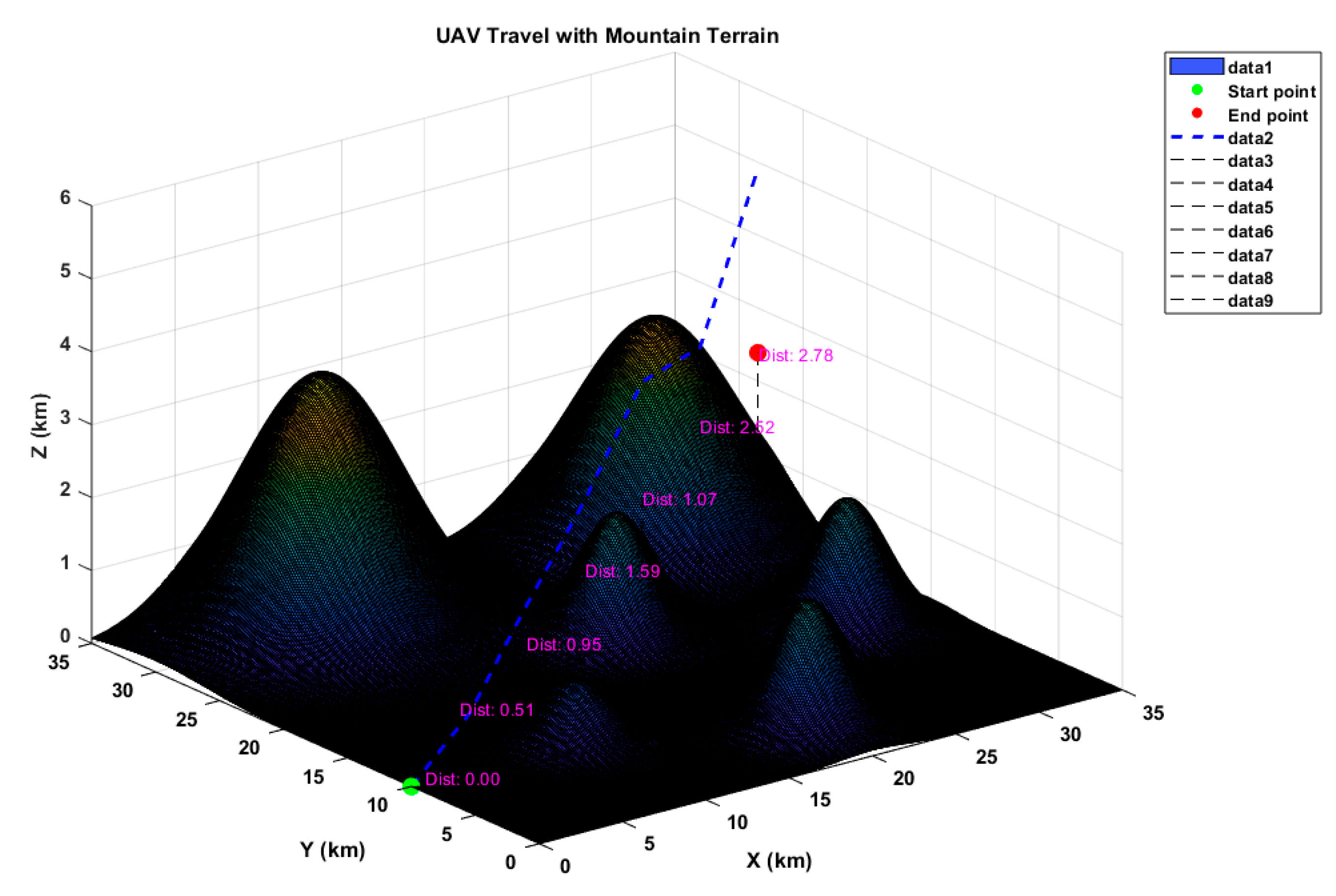
This formulation captures the intricacies of optimizing swarm paths by weighing various costs associated with the route length, terrain challenges, and collision prevention. The Figure 1 shows the graphical overview of UAVs in mission area comprised of mountains

2.3.1. Flying Path Length Cost

Reducing the cost associated with the length of the flying path is imperative in UAV path planning, considering the limited fuel capacity. To optimize fuel usage, the path should be minimized in length. Assuming the entire route comprises “n” legs, the minimal flight path length cost is:
f L E = i = 1 n l i
where
  • i = 1 n  indicates the summation of all path leg lengths from i = 1 to i = n.
  • n is the total number of legs in the route.
  • i is the index of each path leg in the route.
  • l i  denotes the length of i indexed leg in the route.

2.3.2. Mountain Terrain Cost

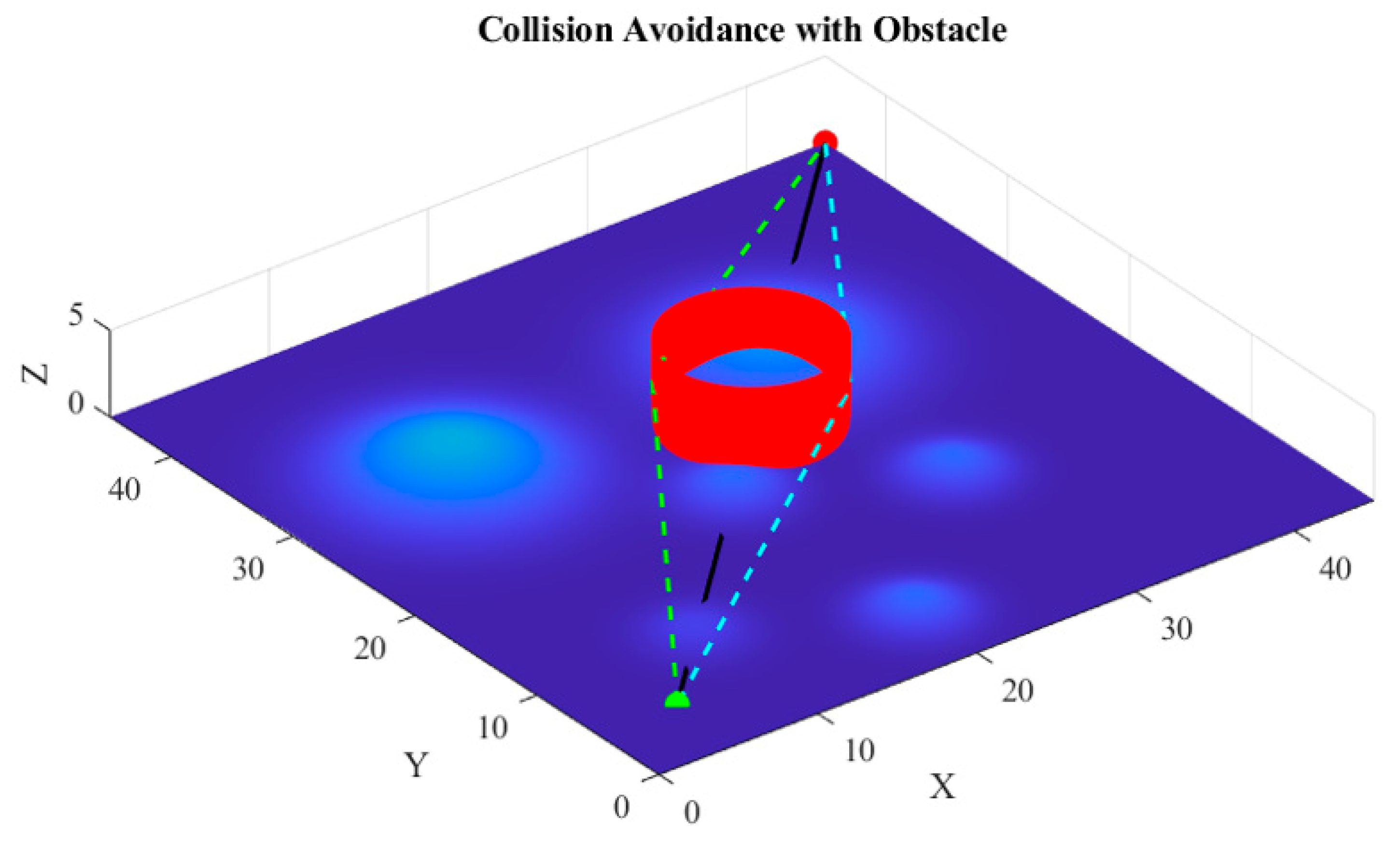
The cost of navigating through mountainous terrain is determined by the distance between the UAVs and the mountains. As the UAVs approach the mountains, the terrain cost increases. The mountain terrain cost is:
f T R = Q a v g R ,   p a t h   n o t   t h r o u g h   t h e   m o u n t a i n s ε ,   p a t h   t h r o u g h   t h e   m o u n t a i n s
a v g   R = i = 1 n r i n
where  Q  represents a value associated with the actual flying range,  ε  denotes the penality constant, “n” indicates the total number of legs, and  r i  signifies the distance between each path leg and the mountain terrain. The concept is elaborated in detail in Figure 2.
The calculated distances represent the distances between the UAV and the mountain at each waypoint. These distances are essential for evaluating the mountain terrain cost, which indicates how close the UAV is to the mountain during its travel. In the context of mountain terrain cost, the distance values represent the vertical distance between the UAV and the mountain surface directly beneath it. This distance helps in assessing the proximity of the UAV to the mountain, which is crucial for determining the terrain cost.

2.3.3. Collision Cost Function

The collision risk within a multiple UAV swarm arises from encounters with obstacles and other UAVs within the swarm. Hence, managing the formation entails addressing both formation control and collision avoidance simultaneously [29,32]. Maintaining the formation requires sufficient separation from both obstacles and other UAVs. Here, we propose an approach employing an indexing technique to tackle collision avoidance. Each UAV is assigned a higher or lower index, with lower-indexed UAVs creating virtual obstacles around higher-indexed ones and maneuvering to avoid them. Timely responses from lower-indexed UAVs are crucial to evade collisions with adjacent UAVs with higher indices or other obstacles [33]. Consequently, a collision avoidance cost function is formulated to mitigate such risks. The cost function of collision avoidance is:
f C O = P c o × i = 1 n u m c o d k i d k i = 1 , d k i d s a f e 0 , d k i > d safe  
Here, ‘Pco’ represents the penalty incurred from collisions, and ‘numco’ denotes the number of collisions that UAVk must prevent. ‘dki’ signifies the distance between UAVk and the i indexed collision center, while ‘dsafe’ denotes the minimum spacing UAVs must maintain to prevent collisions.

2.4. Constraints

The constraints imposed on the optimization model are defined as follows:
l m i n l i l m a x
Equation (8) indicates the permissible range for the flight length, and  i = 1 ,   2 , , n .
ψ i ψ m a x
Equation (9) denotes the restriction on turning angles, where  ψ m a x  represents the maximum allowable turning angle, and  i = 1 ,   2 , , n .
ϑ i ϑ m a x
Similarly, Equation (10) defines the constraints on the climb/dive angles, with  ϑ m a x  indicating the maximum permissible climb/dive angle, and  i = 1 ,   2 , , n .
A i < A m a x
Furthermore, Equation (11), represents the limitation on altitude, where  A m a x  denotes the maximum allowable altitude.
These constraints ensure that the optimization algorithms adhere to the specified criteria, where the flight length, turning angles, climb/dive angles, and altitude are constrained within predefined limits to meet operational requirements.

3. Introduction to UAV Formation with Communication Latency

During the operation of multiple UAV formations, maintaining the coherence of the formation configuration relies on the exchange and sharing of information among formation members. However, due to inherent communication delays during information exchange among members, the stability of the entire system is inevitably affected. Therefore, investigating the issue of consistency in UAV formation systems with communication delays holds practical significance.

Concept of UAV Communication Network Topology

Suppose we have a directed graph G(V, E, A) representing the communication topology, where multiple drones operate in formation. Here, V = {V1, V2, …, Vk} denotes the vertex set, E represents the edge set, and A is the weight adjacency matrix.
The edges of this directed graph are defined as  e m n  =  V m , V n , where  V m  serves as the tail and  V n  as the head of the edge. The weight adjacency matrix  A = a m n  specifies the weight of adjacency between nodes; if  a m n  > 0, it indicates that node ‘m’ can receive information from node ‘n’, otherwise,  a m n  = 0. Additionally, we define the diagonal matrix  D = d i a g   d m   m = 1,2 , , k , where each element  d m  is the sum of the ith row of matrix A. The Laplace matrix of graph G, denoted as L, is given by L = D − A [5,34].
For an undirected graph G (where  a m n = a n m ), the Laplace matrix L is symmetric, positive semi-definite. When G is undirected and all nodes are connected, it is termed as an undirected connected graph. In graph theory, it is known that the Laplace matrix L can be diagonalized to obtain the minimum value  Γ  of the diagonal matrix G, satisfying:
0 = λ 1 < λ 2 λ m a x  
where  λ 1  to  λ m a x  represent the eigenvalues of L. Next, we examine the communication structure of a formation system comprising “n” drones, represented as an undirected connected graph. The dynamic system model of each UAV is approximated using the following second-order equations:
x ˙ m ( t ) = ν m ( t ) ν ˙ m ( t ) = u m ( t ) = 1,2 , , k
To maintain consistency throughout the manuscript, since UAVs’ movements involve direction, using “velocity” is generally more appropriate. Here, ‘xm’ denotes the position status, ‘vm’ signifies the velocity status, and ‘um’ represents the control input of the formation member. To ensure the alignment of formation members with their anticipated movement patterns, a prescribed control protocol is employed. This protocol is expressed as:
u m ( t ) = a m n k 1 x n t τ x m t τ + r m n + k 2 ν n t τ ν m t τ + k 3 h m ν s ν m
Here,  k 1 k 2 , and  k 3  represent system control gains, while ‘ τ ’ denotes the time delay for information transmission between formation members ‘n’ and ‘m’. ‘rmn’ symbolizes the expected relative position between formation members ‘m’ and ‘n’, with ‘vs’ indicating the anticipated formation velocity. The ability index ‘hm’ enables the acquisition of expected velocity information. This protocol, expressed as:
U ( t ) = k j ( L X ( t τ ) diag   ( A R ) ) k 2 L V ( t τ ) k 3 H V ( t ) ν s 1 n × 1
integrates various factors. Additionally, ‘R’ is an ‘n × n’ matrix comprised of elements rij, and  d i a g   ( A R )  represents a vector containing the diagonal elements of A × R.H’ is an n × n diagonal matrix defined by ‘hi’. The vector X(t) comprises the position statuses of formation members, denoted as  X ( t ) = x 1 ( t ) , x 2 ( t ) x k T , while V(t) represents the velocity states of formation members, given by  V ( t ) = v 1 ( t ) , v 2 ( t ) v k T . Finally, U(t) signifies the control input vector for formation members, expressed as U(t) = [u1(t), u2k(t), …,uk]T. The system’s state equation can be expressed as follows:
X ˙ V ˙ = 0 1 0 0 I k 0 0 0 k 3 H X V 0 0 k 1 k 2 L X ( t τ ) V ( t τ ) + 0 k 1 d i a g   ( A R ) + 0 k 3 v s H × I k × 1
In the context of the state equation provided for the UAV formation system, “Ik” stands for the identity matrix of size k × k. In this equation “Ik” ensures that the velocity state vector “V” is correctly combined with the position state vector “X” in the dynamic system model.
The control protocol aims to achieve:
l i m t x m ( t ) x n ( t ) r m n l i m t ν m ( t ) ν n ( t ) 0 l i m t ν m ( t ) = l i m t ν m ν s
This implies that the relative positions of formation members ‘m’ and ‘n’ tend towards the expected relative position  r m n , while the velocities of ‘m’ and ‘n’ converge to the expected velocity ‘ns’. This encapsulates the mathematical representation of the consistency issue within a UAV formation system.

4. Formation Dynamics and Modeling

In this section, we will focus on the details of a UAV model with a fixed configuration and the leader–follower formation model.

4.1. Modeling of Fixed-Wing UAVs

This research primarily focuses on regulating multi-UAV swarms. We adopt the point-mass model to represent our fixed-wing UAVs [3,5,15,16,17,18,19,20,21,22,23,24,25,26,27,28,29,30,31,32,33,34,35]. Here, we consider a swarm of UAVs employing the following model:
x ˙ m = V m c o s   γ m c o s   χ m
y ˙ m = V m c o s   γ m s i n   χ m
h ˙ m = V m s i n   γ m
where ‘xm’ and ‘ym’ represent the longitudinal and lateral displacements, respectively, while ‘hm’ denotes the altitude. Similarly,
V m = T m D m m m g s i n   γ m
γ ˙ m = L m c o s   φ m m m g c o s   γ m m m V m
χ ˙ m = L m s i n   φ m m m V m c o s   γ m
V m  indicates the ground velocity.  γ m  represents the flight path angle,  φ m  denotes the bank angle, and  χ ˙ m  represents the heading angle.  T m  is the thrust,  D m  is the drag,  L m  represents lift, and  m m  and  g  denote the mass and gravitational acceleration, respectively.
Utilizing feedback linearization, the nonlinear model can be linearized as:
x m ¨ = u x m y m ¨ = u y m h m ¨ = u h m
where  u x m u y m ,  and  u h m  are the simulated control inputs associated with UAV movements and altitude variations. The actual control inputs are the bank angle, lift, and thrust, expressed as:
φ m = t a n   1   u y m c o s   χ m u x m s i n   χ m u h m + g c o s   γ m u x m c o s   χ m + u y m s i n   χ m s i n   γ m
L m = m m u h m + g c o s   γ m u x m c o s   χ m + u y m s i n   χ m s i n   γ m cos   φ m
T m = m m u h m + g s i n   γ m + u x m c o s   χ m + u y m s i n   χ m c o s   γ m + D m
Furthermore,  m , xm, and  h m  must satisfy the following dynamic constraints:
V min   V m V m a x
χ m n m a x g / V m
λ m i n h m λ m a x
where  V min    and  V m a x  represent the lowest and highest velocities,  n m a x  is the maximum lateral overload, and  λ m i n    and  λ m a x  are the lowest and highest climbing velocities, respectively.

4.2. Formation Control with Leader–Follower Dynamics

In the pursuit of effective formation control for multi-UAV swarms, a point mass model is employed, allowing each UAV to navigate at a consistent altitude within the three-dimensional operational space. The model delineates the dynamics governing the formation as follows:
x ˙ i = V F , i c o s   ψ E , i c o s   μ E , i μ ˙ L z i + ψ ˙ L y i V L , i
y ˙ i = V F , i s i n   ψ E , i c o s   μ E , i ψ ˙ L x i
z ˙ i = V F , i s i n   μ E , i μ ˙ i x i
μ E , i = μ L f μ F , i f
ψ E , i = ψ L f ψ F , i f
Here, (xi, yi, and zi) represent the current coordinates of the i-th UAV, while  V F , i  and  V L , i  denote the angular and lateral velocities of i-th UAV, respectively. Additionally,  ψ E , i  is the heading angle difference in the horizontal plane for the i-th UAV, and  μ E , i  is the heading angle difference in the vertical plane for the i-th UAV. ψL and µL are the angular velocities related to the leader UAV. ΨF,i and µF,i are angular velocities related to the i-th follower UAV. The desired leader–follower configuration, depicted in Figure 3, elucidates the followers’ adherence to the leader’s trajectory, with neighboring UAVs serving as references to uphold the formation’s integrity. In larger formations, it is imperative to maintain consistent spacing between UAVs, a challenge exacerbated in scenarios involving dynamic threats, as observed in scenario 2, where slight deviations in the inter-UAV distances are inevitable [36,37].
This study advocates leader–follower formation control, wherein each follower tailors its trajectory in accordance with the leader’s path, maintaining a constant altitude across all UAVs. Notably, a simulated leader is employed instead of a physical counterpart, affording followers the flexibility to adjust their velocity and direction in tandem with the simulated leader’s guidance. This approach mitigates the risk associated with potential malfunctions of a real leader, ensuring robust and efficient formation control throughout the mission [38,39].

5. Hybrid Approach for Formation Control

5.1. Classical PSO

Particle swarm optimization (PSO) serves as a computational strategy inspired by the collective behaviors observed in natural swarming phenomena of fish and bird flocks [40]. Its iterative process begins with the initialization of random solutions, iteratively updating both the position and velocity to converge towards an optimal global solution. Each particle dynamically adjusts its search direction based on its prior performance, individual best outcome, and the overall best outcome within the swarm. If the newly calculated position surpasses its predecessors, it becomes the individual best position; likewise, if it outperforms all other positions, it assumes the global best position. Initially introduced by, PSO orchestrates a swarm of particles traversing the search space to discover the optimal solution. Mathematically, each particle i within the D-dimensional space possesses position and velocity vectors, which are represented as:
V i = V i 1 , V i 2 , , V i D , i = 1,2 , , N
X i = X i 1 , X i 2 , , X i D , i = 1,2 , , N
Here,  V i  and  X i  represent the velocity and position vectors of individual particle  i , respectively, while D represents the number of dimensions, and  N  signifies the swarm size. During the initiation of the PSO optimization procedure, the velocity and position of each particle are randomly set within predefined ranges.
Here,  V i  and  X i  denote the velocity and position vectors of particle  i , respectively, while D represents the number of dimensions, and  N  signifies the swarm size. At the onset of the PSO optimization process, the velocity and position of each particle are randomly initialized within predefined ranges. Throughout the iterative process, each particle is guided by both the global best particle (gbest = [gbest1, gbest2, …, gbestD]), representing the best solution found thus far, and its personal best position (Pbest = [Pbest1, Pbest2, …, PbestD]) to update its velocity and position according to:
V i d ( t + 1 ) = w V i d ( t ) + c 1 r 1   Pbest   i d ( t ) X i d ( t ) + c 2 r 2   gbest   d ( t ) X i d ( t )
X i d ( t + 1 ) = X i d ( t ) + V i d ( t + 1 )
In this formulation,  w  represents the inertia weight,  c 1  and  c 2  denote the cognitive and social acceleration coefficients, respectively, while  r 1  and  r 2  are random variables uniformly distributed in the range [0, 1]. Notably,  w c 1 , and  c 2  play pivotal roles in balancing the PSO’s exploration and exploitation capabilities. Subsequently, a particle updates its personal best position according to:
P b e s t i   ( t + 1 ) = X i ( t + 1 )   if   f X i ( t + 1 ) < f P b e s t i   ( t ) P b e s t i   ( t )   otherwise  
where the personal best position of particle  i  is only updated if the fitness of the newly generated particle  X i  surpasses the current fitness of  P b e s t i . The next iteration involves updating  g b e s t  based on:
g b e s t   ( t + 1 ) = P b e s t i   ( t + 1 )   if   f   Pbest   i ( t + 1 ) < f ( gbest   ( t ) ) g b e s t   ( t )   otherwise  
The PSO process continues until a predefined stopping criterion is met, ensuring the convergence towards an optimal solution.

5.2. Velocity-Pausing PSO

In VPPSO, particle velocities are dynamically adjusted to balance exploration and exploitation during optimization. The velocity update equation incorporates a parameter, α, controlling the probability of velocity pausing at each iteration:
V i ( t + 1 ) = V i ( t ) i f r a n d < α w V i ( t ) O t h e r w i s e + c 1 r 3 P b e s t i   ( t ) X i ( t ) + c 2 r 4 g b e s t   ( t ) X i ( t )
This novel concept prevents premature convergence while maintaining diversity within the swarm. The modified velocity equation includes a term dependent on the iteration count  t :
V i ( t + 1 ) = V i ( t ) r 5 a ( t ) + c 1 r 6 Pbest   i ( t ) X i ( t ) + c 2 r 7 g b e s t   ( t ) X i ( t )
where  a ( t ) = e x p b t T b , enhancing the exploration by adjusting velocity updates over time. Additionally, VPPSO employs a two-swarm strategy: one swarm follows traditional PSO with velocity pausing, while the other updates positions based solely on the global best:
X i t + 1 = g b e s t + a ( t ) r 8 g b e s t   | a t i f   r 9 < 0.5 g b e s t a ( t ) r 10 g b e s t   | a t O t h e r w i s e
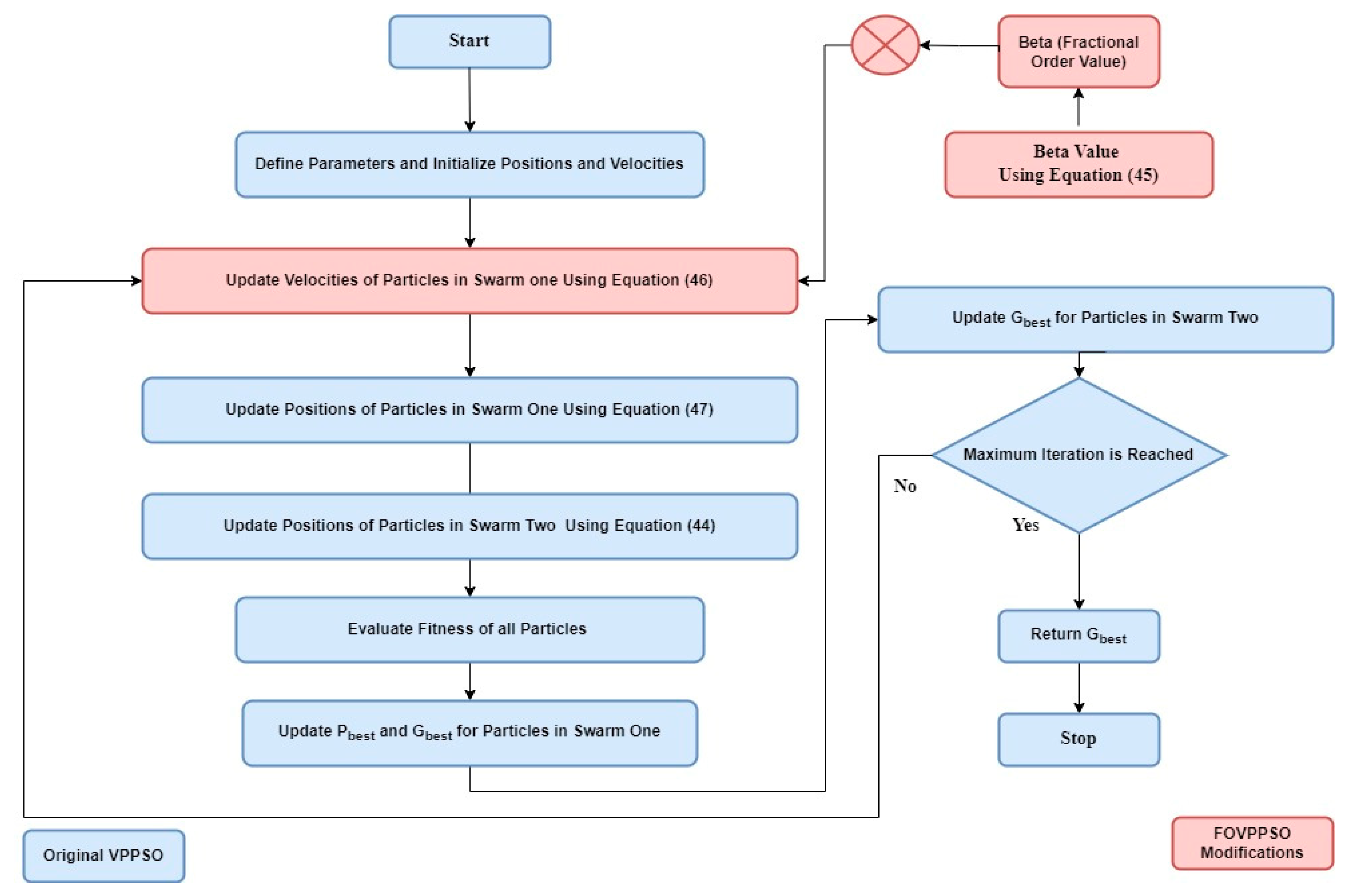
This approach ensures a balance between exploration and exploitation, leading to efficient optimization. In short, VPPSO introduces innovative modifications to the PSO algorithm, leveraging velocity pausing and a two-swarm strategy to tackle complex optimization challenges effectively. The working methodology of FO-VPPSO is shown in Figure 4.

5.3. Fractional Order Hybrid PSO

The addition of fractional order in velocity-pausing PSO (VPPSO) aims to enhance the algorithm’s adaptability and exploration–exploitation balance, leading to potentially improved optimization performance [41]. Prime issues seen when utilizing the classical PSO algorithm are pre-mature convergence and imbalanced exploration–exploitation. The fractional order value β is included in the equations for velocity update to enhance the performance of the algorithm. The mathematical equation for calculating the value of the fractional order β based on the convergence trend is given by the equation:
β = m a x 1   weighted _ avg _ improvement     threshold     weighted _ convergence _ rate ,   m i n i m u m _ b e t a
Equation (45) adjusts the fractional order value  β  dynamically based on the average improvement and convergence rate of the objectives, aiming to maintain a balance between exploration and exploitation during the optimization process. Hence, the function dynamically adjusts β based on the convergence trend, preventing premature convergence by balancing exploration and exploitation.
Now, the term  1   weighted _ avg _ improvement     threshold    measures the relative improvement achieved compared to the threshold. If the improvement is high (i.e., objectives are improving rapidly), this term will be close to 0, indicating that  β  should be larger. Conversely, if the improvement is low, this term will be larger than 1, suggesting that  β  should be smaller.
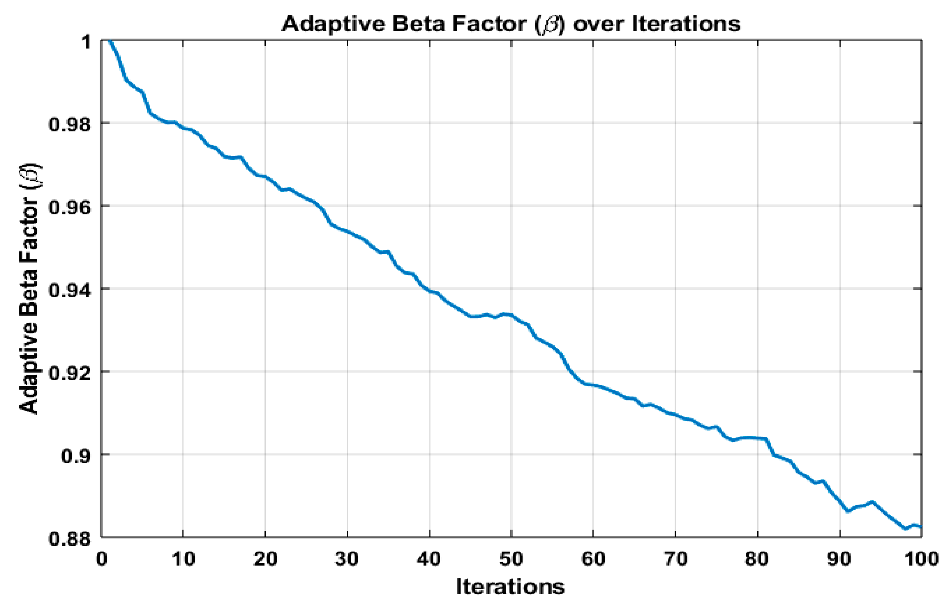
The Weight_Convergence_rate term represents the convergence rate of the objectives. A higher convergence rate indicates that the objectives are changing rapidly, possibly suggesting that the optimization process is unstable or nearing convergence. By subtracting the convergence rate from the first term, the equation ensures that  β  is reduced when objectives are converging rapidly. Moreover, the weighted convergence rate term adjusts β downwards when the objectives are converging rapidly, indicating a need for more exploitation. This term is subtracted from the first term to reduce β during high convergence rates, ensuring that the algorithm does not converge prematurely. As can be seen in Figure 5, the adaptive beta factor varies dynamically as the iteration goes on to keep a balanced exploration and exploitation. At the beginning, the value of β is 1. This makes sense because initially, the algorithm should allow for maximum exploration, since there is no prior information about the search space.
The velocity and position update equations for the fractional-order velocity-pausing PSO (FOVPPSO) can be extracted as follows:
V i ( t + 1 ) = V i ( t ) β a ( t ) + c 1 r 6 P b e s t i ( t ) X i ( t ) + c 2 r 7 gbest   ( t ) X i ( t )
where  V i (t) is the velocity of particle ‘ i ’ at iteration ‘ t ’, and ‘β’ is the adaptive fractional order, adjusted based on the convergence trend.  a ( t )  is the adaptive factor that decays with time ‘ t ’.  c 1  and  c 2  are the cognitive and social acceleration coefficients, respectively.  r 6  and  r 7  are random variables uniformly distributed in the range [0, 1].  P b e s t i ( t )  and  gbest   ( t )  are the personal best position and global best position at iteration ‘ t ’, respectively.  X i ( t )  is the current position of particle ‘i’ at iteration ‘ t ’. The position update equation for each particle i at iteration t + 1 is given by:
X i ( t + 1 ) = X i ( t ) + V i ( t + 1 )
where  X i ( t + 1 )  is the updated position of particle ‘i’ at iteration  ( t + 1 ) .

5.4. Hybrid Algorithm

Step 1:
The 3D mission environment and terrain model are developed based on the specifications of the task. The starting and ending points for the UAV swarm are established.
Step 2:
The parameters are initialized, including the total particle number N, the particle position and velocity matrices, β (fractional order), c1, c2, the maximum number of iterations T, the communication range, and other relevant parameters.
Step 3:
The fitness function is designed considering the objectives and constraints of the optimization problem. The fitness function should reflect the performance metrics to be optimized, such as the flight length, terrain cost, and collision cost.
Step 4:
Objective functions:
The objectives (flight length, terrain cost, and collision cost) are aggregated into the fitness function that evaluates each UAV’s (particle’s) performance.
The fitness function directly influences the velocity and position updates, guiding the swarm towards optimal solutions that balance these objectives.
Step 5:
The fitness functions of the entire swarm are monitored, and the optimal positions for each UAV are computed as well as the optimal position for the formation.
Step 6:
Updating the parameters dynamically:
The fractional order β is updated based on the convergence trend using the calculate_adaptive_beta function. The inertia weight w and c1 and c2 coefficients are adjusted if necessary to balance exploration and exploitation.
Step 7:
Updating the particles:
The velocity and position of the particles are updated using the FOVPPSO algorithm with velocity pausing and fractional-order dynamics.
Step 8:
Tuning parameters to swarm position:
The position of each UAV in the swarm is updated using the velocity update Equation (44) of FO-VPPSO, which is influenced by the adaptive value β and coefficients c1 and c2.
As the UAVs navigate the 3D mission environment, their positions represent the search space explored by the FO-VPPSO particles.
Step 9:
Steps 4–6 are repeated until the maximum iterations T are reached.
Step 10:
The hybrid algorithm is finished, and the results are analyzed:
The convergence of the fitness functions is plotted over the iterations to observe the algorithm’s performance.
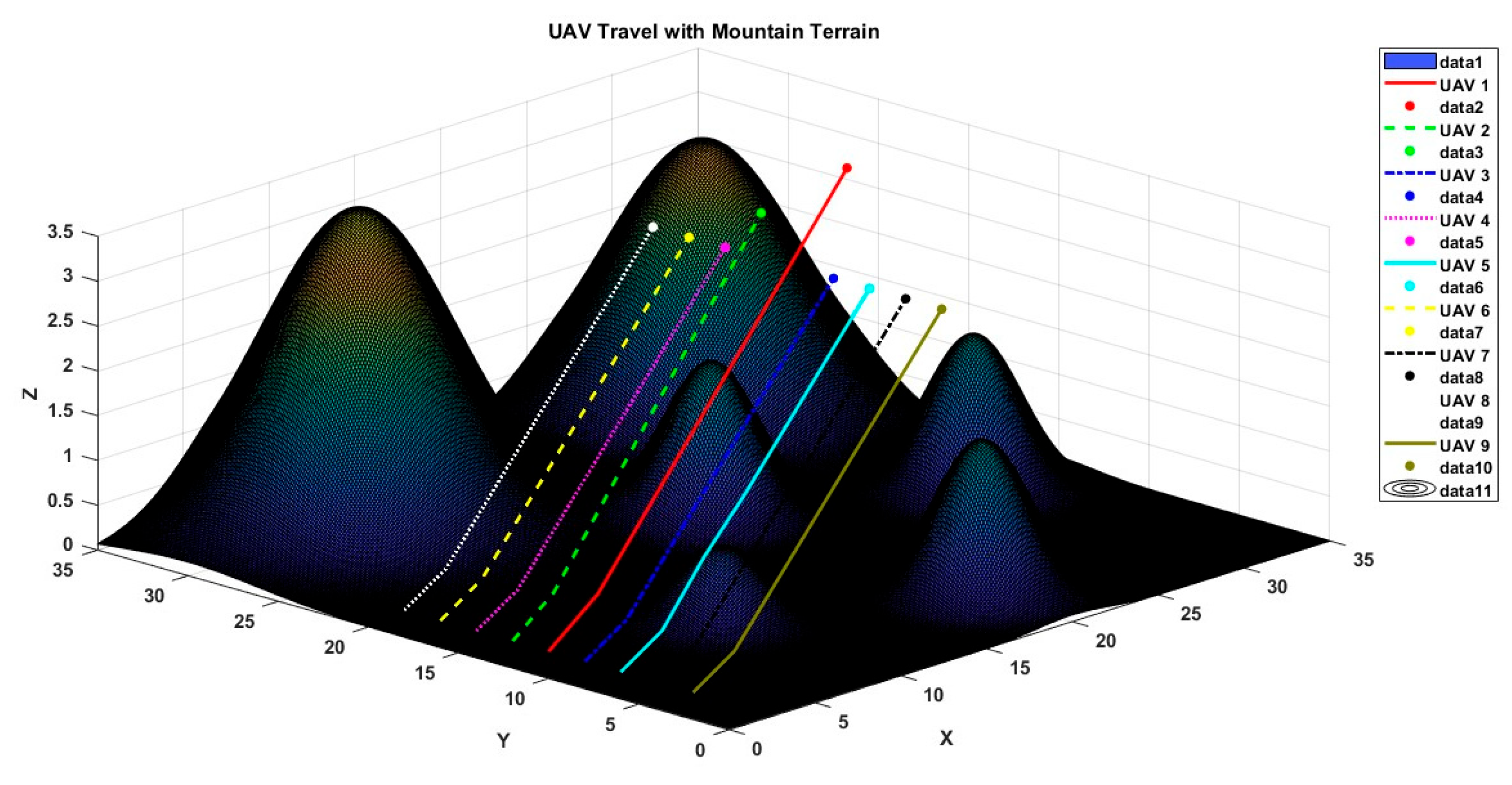
A visual graphical abstract, explaining the complete scenario is provided here in Figure 6.

6. Experimental Analysis and Findings

In this section, firstly, the performance of the optimization techniques is evaluated using standard benchmark functions, both for single and multiple models, which are commonly used methods. The optimizer with the lowest rate of error is deemed the most optimum and is recognized as a competent optimizer. This research uses a comprehensive collection of 13 benchmark functions to assess the effectiveness of different optimization methods in a wide range of circumstances. The first seven functions, labeled as F1 to F7, are categorized as unimodal functions, whereas functions from F8 to F13 are considered to be multimodal functions. FOVPPSO produces the most favorable results in every unique testing situation. The numerical results are shown in Table 1, which exhibits the effectiveness of FOVPPSO based on the mean fitness value over 100 independent iterations, and it was observed that FOVPPSO outperformed other state-of-the-art optimizers. Furthermore, to demonstrate the efficacy of our proposed technique through simulations conducted in diverse environments, the simulations were executed on a computer equipped with an Intel Core i5-1065G7 processor, running a 64-bit Windows 10 operating system, and having 8 GB of RAM. MATLAB R2022a(R) was utilized for conducting the simulations. Our algorithm was tested in two distinct scenarios aimed at capturing common challenges encountered by both civilian and military operations. The first scenario only included mountainous terrain to be covered. The second scenario included a more complex nature, with moveable objects included in the terrain. Some static obstacles were also added into the algorithm to make detection and avoidance a challenging task.

6.1. Scenario 1

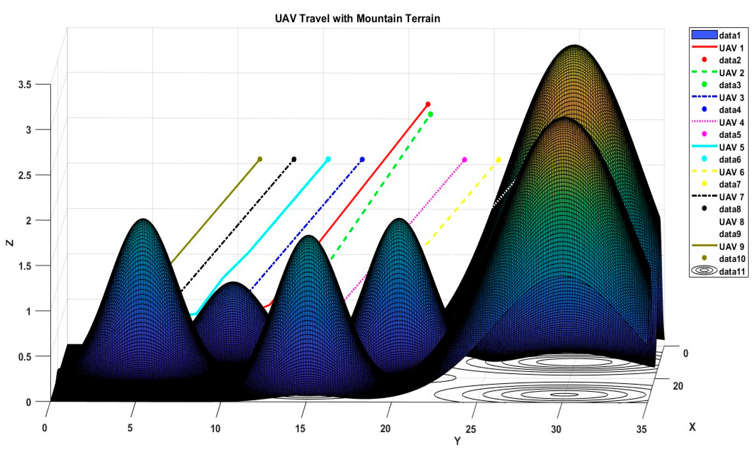
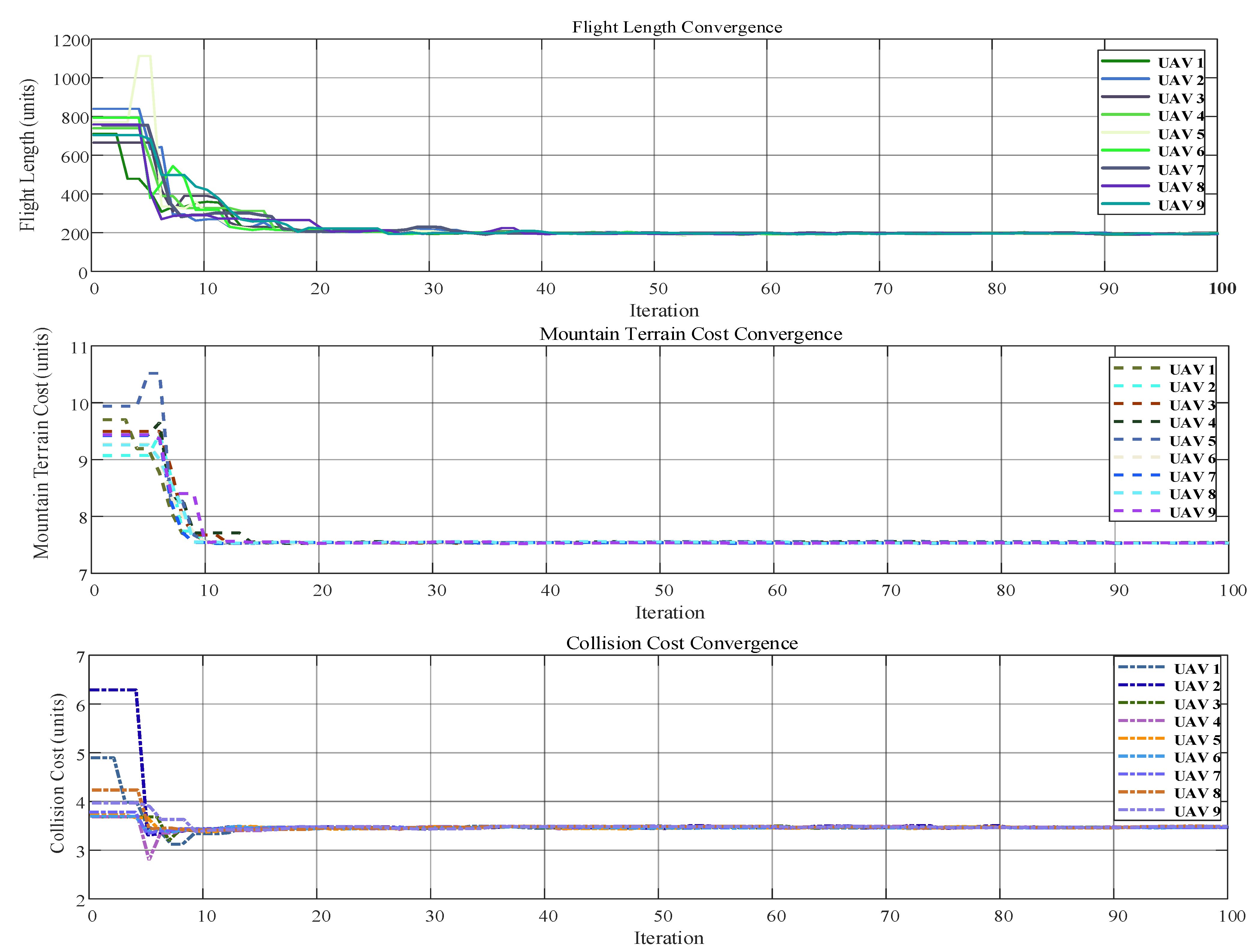
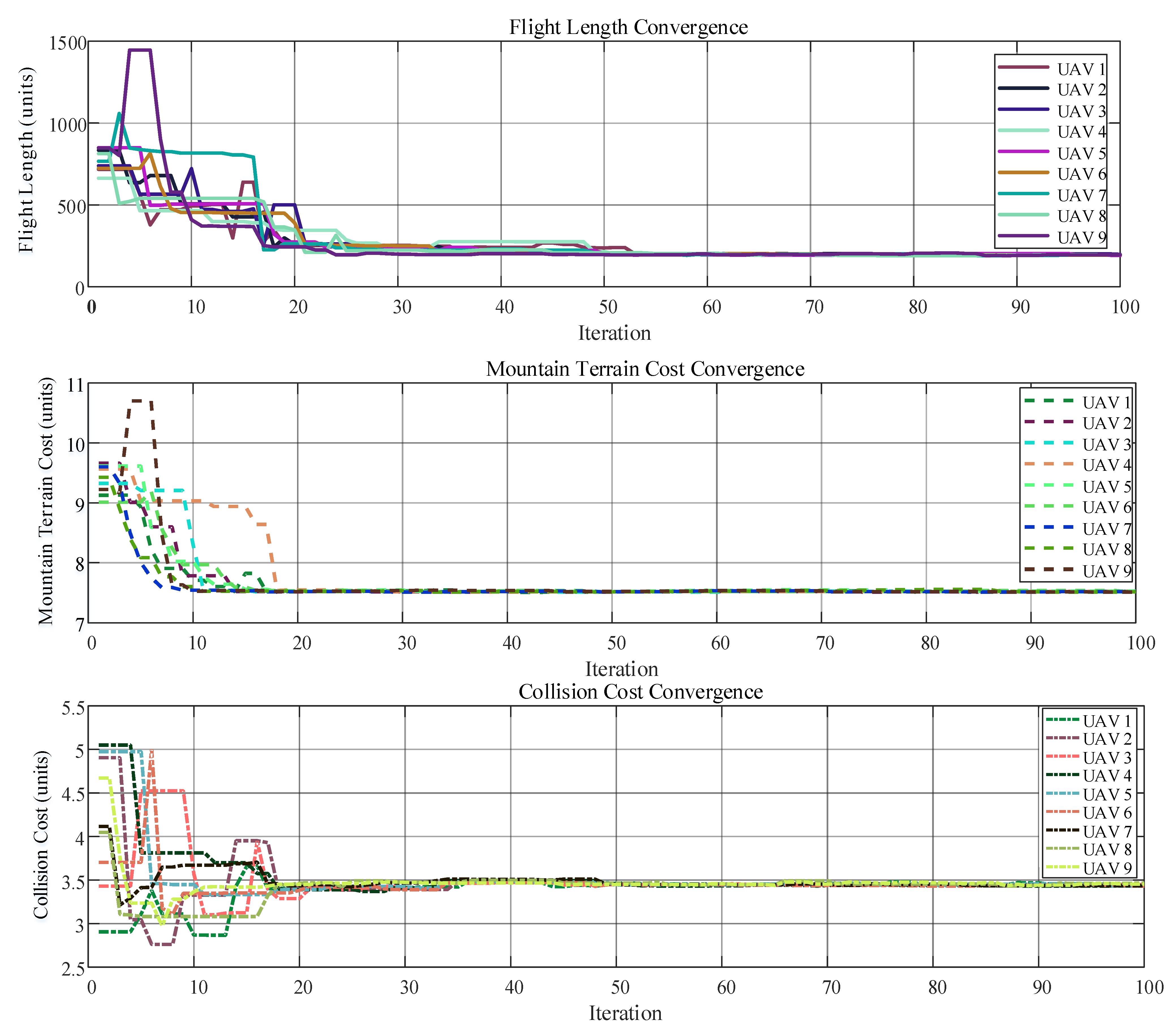
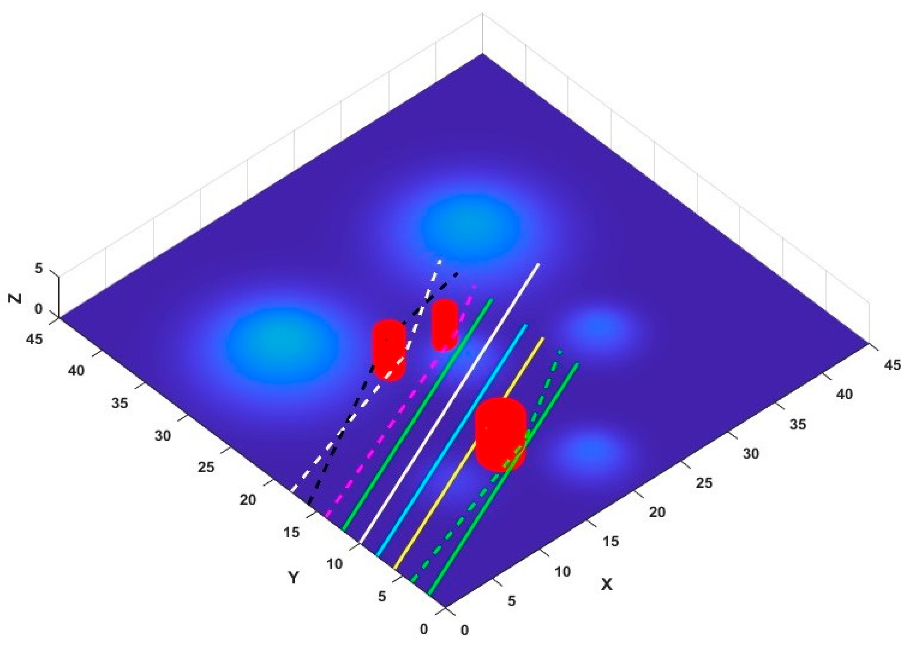
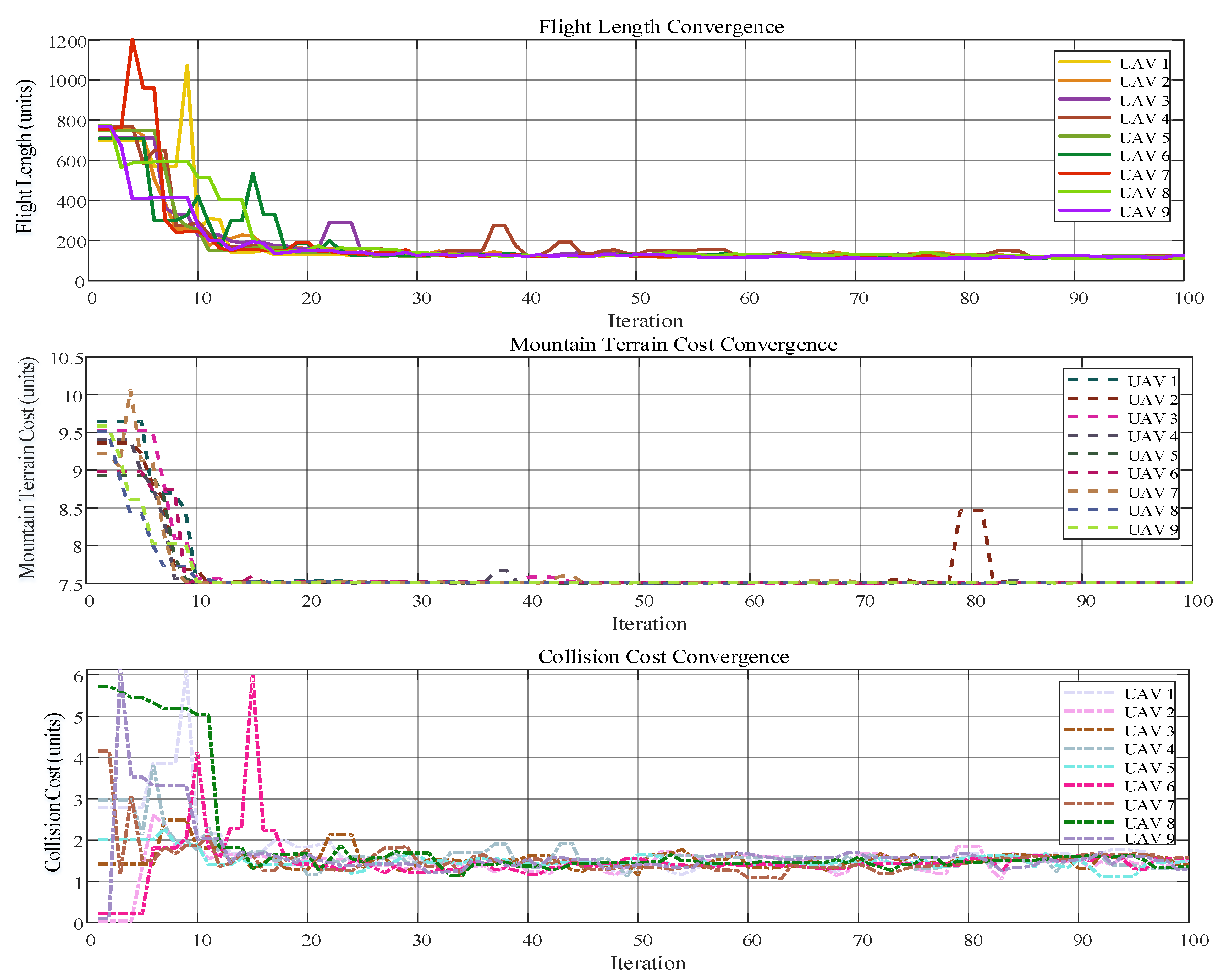
Scenario 1 involves a mountainous terrain through which a formation of nine UAVs must navigate from the origin to the target. This scenario features six mountains, each imposing constraints parameters, as detailed in Table 2. The objectives for the swarm in this scenario include avoiding collisions with the mountains and other UAVs, maintaining formation, and selecting the shortest route to the destination. Visual representations of the 3D environment, including mountain peaks, are depicted in Figure 7, with subsequent figures displaying the swarm’s path in the xyz-planes, xz-planes (Figure 8), and yz-planes (Figure 9). Additionally, Figure 10 illustrates the fitness levels of all UAVs across multiple iterations, with a zoomed-in view provided for clarity due to the complexity of visualizing nine UAVs simultaneously. Notably, the leader exhibits the shortest convergence time due to covering the most extensive distance. The convergence characteristic graphs obtained during the course of simulation via FOVPPSO and VPPSO for the flight length, mountain terrain, and collision cost are shown in Figure 10 and Figure 11, and it has been realized that FOVPPSO performs better than VPPSO in terms of the quality of the solution, convergence characteristic of the optimizer, and achieving the optimum solution in a fewer number of iterations as compared to its VPPSO; also, the fitness progression of all UAVs is shown over numerous iterations, albeit with some difficulty in interpretation due to the number of UAVs involved. Comparisons with the fitness levels achieved using traditional PSO and the VPPSO method proposed by [26] reveal our technique’s superior performance, with fitness levels ranging from 10 to 20 compared to VPPSO and classical PSO. Finally, Table 3 summarizes the starting positions, destinations, and distances traveled by each UAV during the mission, demonstrating deliberate variations in the origin points to prevent collisions.
F 12 ( x ) = π n 10 s i n   π y 1 + i = 1 n 1 y i 1 2 1 + 10 s i n 2   π y i + 1 + y n 1 2 + i = 1 n u x i , 10,100,4 y i = 1 + x i + 1 4 u x i , a , k , m = k x i a m x i > a 0 a < x i < a k x i a m x i < a
F 13 ( x ) = 0.1 s i n 2   3 π x 1 + i = 1 n x i 1 2 1 + s i n 2   3 π x i + 1 + x n 1 2 1 + s i n 2   2 π x n + i = 1 n u x i , 5,100,4

6.2. Scenario 2

Scenario 2 entails a simulation where a group of nine UAVs is tasked with navigating from the starting point to the destination within an environment containing both static and dynamic obstacles. The scenario comprises three distinct obstacles, each with specified constraints as outlined in Table 4, along with the placement details of moveable objects, provided in Table 5.
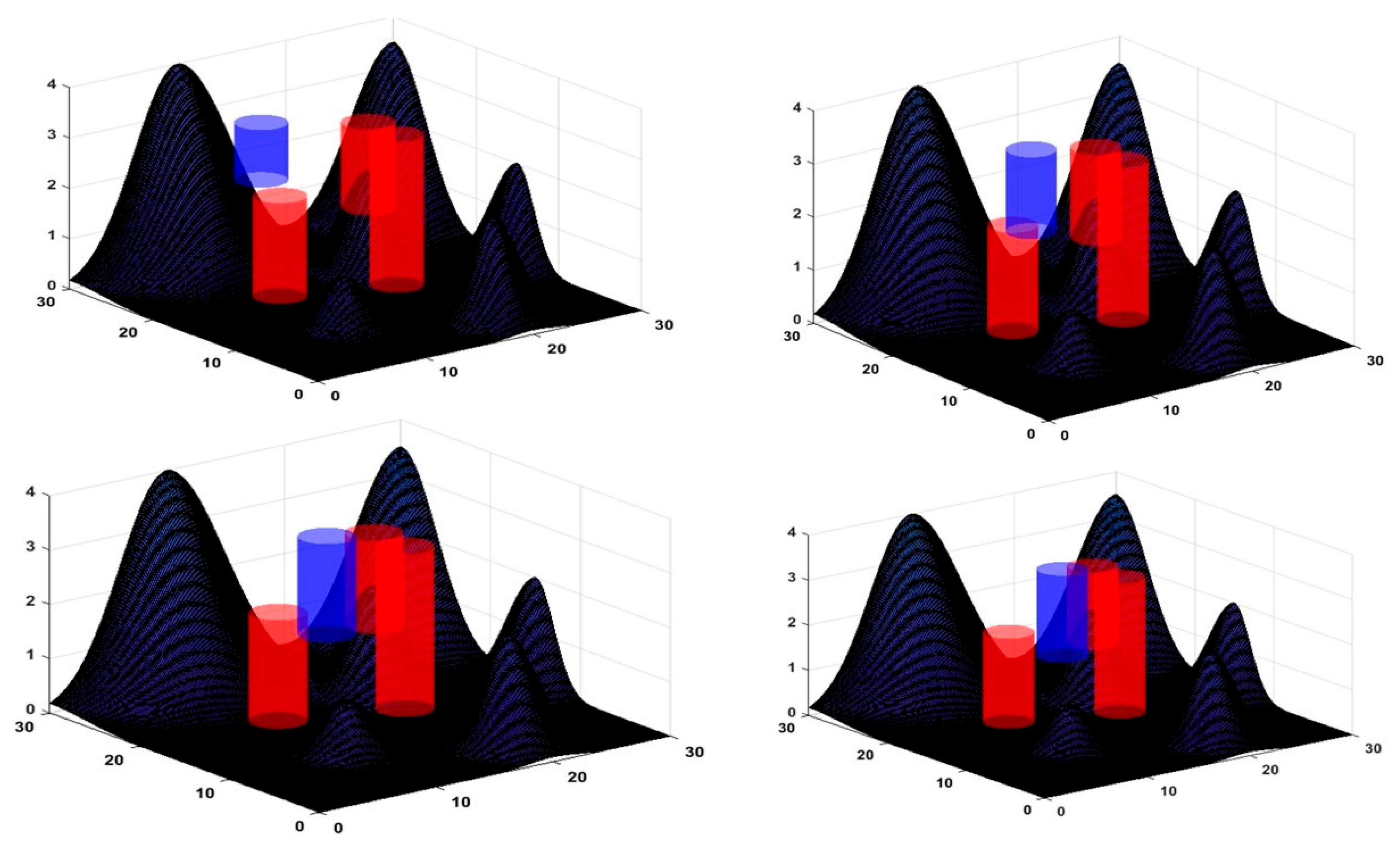
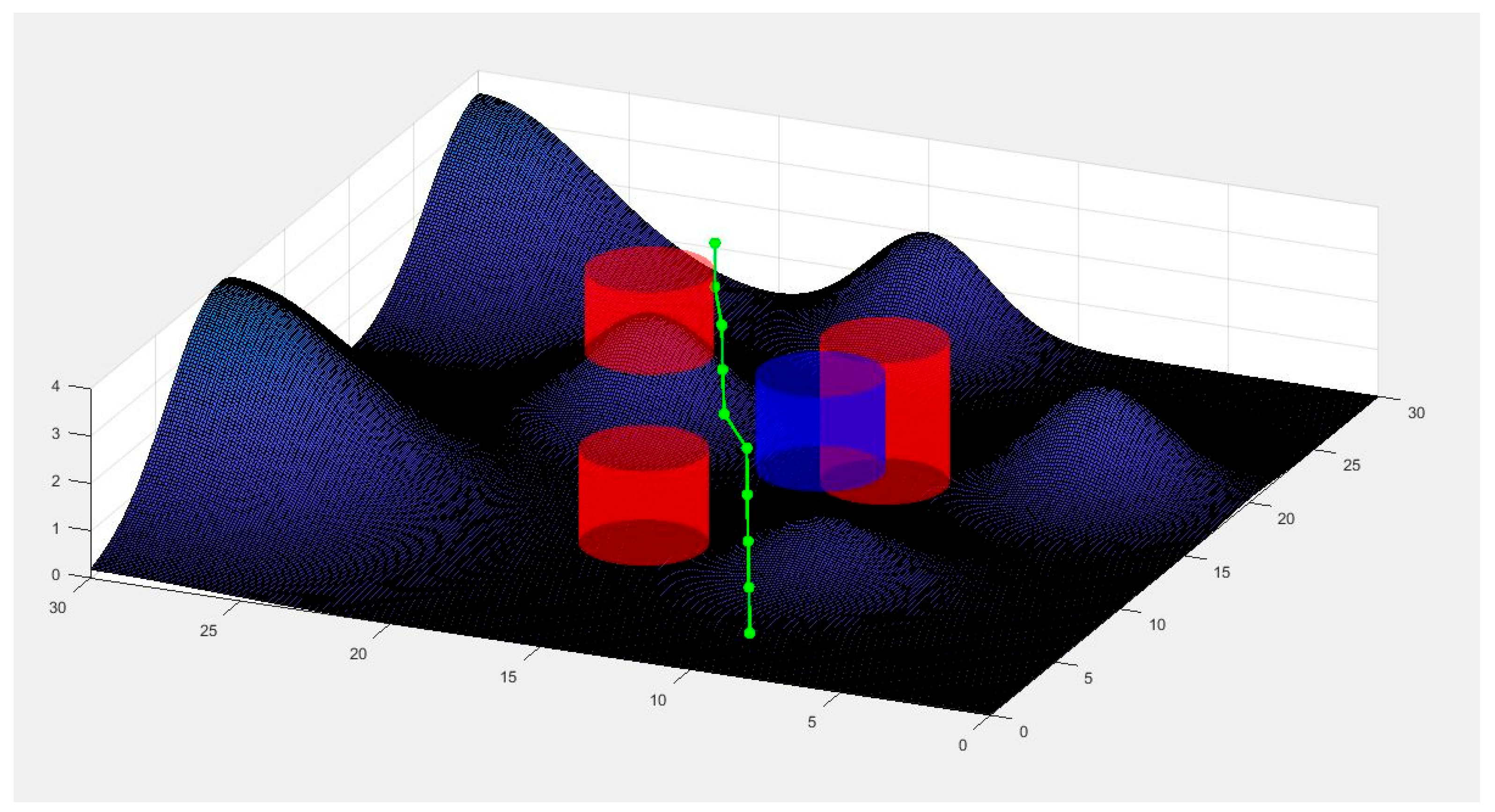
Within this setting, the swarm of UAVs must achieve five primary objectives: avoiding collision with a moveable object by continuous measurements of the object position, circumventing obstacles, steering clear of other UAVs, preserving formation integrity, and selecting the most efficient route to the destination. Figure 12 provides depictions of the environment from multiple perspectives, showcasing the dynamic object trajectory while navigating around obstacles and terrain. The red colored cylinders show the static obstacles placed at different coordinates of terrain, whereas the blue cylindrical structure shows the moveable dynamic object. The green arrow points towards the dynamic obstacle at different positions inside the terrain.
Due to the random trajectory of dynamic threats, this leads to major deviations compared to Scenario 1. Furthermore, Figure 13 explains the concept of actual path deviation in both directions due to an obstacle. Figure 14 provides an insight into the behavior of the swarm in the case of an obstacle, and how the specific UAVs within the swarm that confront some obstacles possess obstacle detection and path deviation abilities to avoid collision. Figure 15 shows a clear image of the leader UAV performing a path deviation throughout the terrain while avoiding a collision with the dynamic obstacle, as well as when it comes into the trajectory of the leader UAV.
Figure 16 and Figure 17 illustrate the fitness progression of all UAVs over numerous iterations, albeit with some difficulty in interpretation due to the number of UAVs involved. To address this, a zoomed-in segment of the graph is provided for clarity. Notably, both the leader and eight follower UAVs exhibit longer convergence times owing to the heightened complexity of the mission environment. Specifically, the collision cost function convergence graph shows abrupt behavior at the start to detect the trajectory of the dynamic obstacle and plan accordingly. The starting positions, destinations, and the distances traveled by each UAV throughout the scenario are shown. Once again, distinct origin points are assigned to each UAV to prevent collisions. The convergence characteristic graph obtained during the course of simulation via FOVPPSO and VPPSO for the flight length, mountain terrain, and collision cost further demonstrate that FOVPPSO performs better than VPPSO in terms of the quality of the solution, convergence characteristic of the optimizer, and achieving the optimum solution in a fewer number of iterations as compared to its counterpart.
Also, to determine the efficiency of the proposed hybrid algorithm, the distance, mountain terrain cost, and collision avoidance are used as evaluation indices, and the comparison results are shown in Table 6.
These results highlight that the FO-VPPSO algorithm achieves the shortest flight length and the lowest mountain terrain cost, indicating its efficiency in path optimization and navigation through challenging terrains. Despite having a slightly higher collision cost compared to PSO, FO-VPPSO balances well between all metrics, demonstrating its robustness and effectiveness for UAV swarm-formation control in dynamic environments.

7. Implementations

Transitioning from simulation to hardware implementation involves several considerations. We envision deploying our technique on embedded systems or specialized hardware platforms suitable for UAV swarm control. These platforms may include microcontrollers or embedded computing units equipped with communication modules for inter-UAV communication. Additionally, integrating our algorithm with onboard sensors and actuators enables real-time decision making and control.

7.1. Sensors

The number and type of sensor required depend on the specific application and the level of autonomy desired. Common sensors for UAVs include GPS for localization, IMU for attitude estimation, and obstacle detection sensors (e.g., LiDAR and cameras) for environment perception. The exact sensor configuration would be tailored to the mission objectives, such as terrain mapping, surveillance, or search and rescue operations.

7.2. Potential Challenges

Deploying UAV swarm algorithms in real-world scenarios presents various challenges, including communication constraints, energy management, environmental variability, and safety considerations. Ensuring robustness in regard to communication delays, handling dynamic environments, and addressing hardware limitations are key challenges to overcome. Moreover, integrating fault tolerance mechanisms and adapting to unforeseen conditions are crucial for mission success.

7.3. Computational Complexities

The computational complexity of our method depends on factors such as the swarm size, dimensionality of the optimization problem, and algorithmic complexity. While our proposed FO-VPPSO algorithm introduces additional computational overhead compared to traditional PSO variants, its benefits in terms of convergence speed and solution quality justify the computational cost. We aim to optimize the algorithm for efficiency without compromising performance, leveraging techniques such as parallelization and hardware acceleration where applicable.

8. Conclusions

In the context of mountainous terrain, this study delved into the complex task of coordinating a multi-UAV swarm effectively. Initially, the paper meticulously crafted models for terrain mapping, radar coverage, and collision evaluation. Subsequently, it explored the fundamentals of the particle swarm optimization (PSO) algorithm and its inherent traits. Leveraging insights from these discussions, the research devised a groundbreaking approach by integrating Fractional Order Calculus and the concept of velocity pausing into a hybrid algorithm framework. This novel algorithm not only surpassed traditional VPPSO in terms of fitness but also exhibited remarkable capabilities in pathfinding amidst obstacles and other UAVs. Crucially, it facilitated the maintenance of formation and adherence to coordination parameters.
The simulations conducted validated the efficacy of the hybrid algorithm in achieving optimal path solutions while navigating through challenging terrains. Looking ahead, future investigations could concentrate on refining the fitness function and minimizing the costs associated with terrain mapping, radar coverage, and collision avoidance. Moreover, there is a notable proposal to transition the algorithm from simulation to hardware implementation, paving the way for practical experimentation. By scrutinizing the outcomes of both simulated and real-world tests, researchers aim to discern any performance differentials and fine-tune the algorithm accordingly. Such comparative analysis holds the potential to unveil nuances in algorithmic behaviors across virtual and physical environments, thereby fostering continuous enhancement and optimization.

Author Contributions

Conceptualization, A.W. and A.M.A.; Methodology, A.-F.Y.; Software, A.-F.Y.; Validation, A.W. and A.M.A.; Formal analysis, A.-F.Y.; Investigation, A.W. and A.M.A.; Writing—original draft, A.-F.Y.; Writing—review & editing, A.W. and A.M.A.; Supervision, A.W. and A.M.A. All authors have read and agreed to the published version of the manuscript.

Funding

This research received no external funding.

Data Availability Statement

The original contributions presented in the study are included in the article, further inquiries can be directed to the corresponding authors.

Conflicts of Interest

The authors declare no conflicts of interest.

References

  1. Shakhatreh, H.; Sawalmeh, A.H.; Al-Fuqaha, A.; Dou, Z.; Almaita, E.; Khalil, I.; Othman, N.S.; Khreishah, A.; Guizani, M. Unmanned Aerial Vehicles (UAVs): A Survey on Civil Applications and Key Research Challenges. IEEE Access 2019, 7, 48572–48634. [Google Scholar] [CrossRef]
  2. Qingtian, H. Research on Cooperate Search Path Planning of Multiple UAVs Using Dubins Curve. In Proceedings of the 2021 IEEE International Conference on Power Electronics, Computer Applications, ICPECA 2021, Shenyang, China, 22–24 January 2021; Institute of Electrical and Electronics Engineers Inc.: New York, NY, USA, 2021; pp. 584–588. [Google Scholar]
  3. Ali, Z.A.; Han, Z.; Masood, R.J. Collective motion and self-organization of a swarm of UAVS: A cluster-based architecture. Sensors 2021, 21, 3820. [Google Scholar] [CrossRef] [PubMed]
  4. Cetin, O.; Yilmaz, G. Real-time Autonomous UAV Formation Flight with Collision and Obstacle Avoidance in Unknown Environment. J. Intell. Robot. Syst. 2016, 84, 415–433. [Google Scholar] [CrossRef]
  5. Duan, Z.; Shen, J. Synchronization problem of 2-D coupled dynamical networks with communication delays and missing measurements. Multidimens. Syst. Signal Process. 2017, 30, 39–67. [Google Scholar] [CrossRef]
  6. Jabbarpour, M.R.; Malakooti, H.; Noor, R.M.; Anuar, N.B.; Khamis, N. Ant colony optimisation for vehicle traffic systems: Applications and challenges. Int. J. Bio-Inspired Comput. 2014, 6, 32–56. [Google Scholar] [CrossRef]
  7. Pehlivanoglu, Y.V. A new vibrational genetic algorithm enhanced with a Voronoi diagram for path planning of autonomous UAV. Aerosp. Sci. Technol. 2012, 16, 47–55. [Google Scholar] [CrossRef]
  8. Olfati-Saber, R. Flocking for multi-agent dynamic systems: Algorithms and theory. IEEE Trans. Autom. Control 2006, 51, 401–420. [Google Scholar] [CrossRef]
  9. Ren, W. Consensus strategies for cooperative control of vehicle formations. IET Control. Theory Appl. 2007, 1, 505–512. [Google Scholar] [CrossRef]
  10. Lin, Z.; Wang, L.; Han, Z.; Fu, M. Distributed formation control of multi-agent systems using complex laplacian. IEEE Trans. Autom. Control. 2014, 59, 1765–1777. [Google Scholar] [CrossRef]
  11. Nor, M.H.M.; Ismail, Z.H.; Ahmad, M.A. Broadcast control of multi-robot systems with norm-limited update vector. Int. J. Adv. Robot. Syst. 2020, 17, 1729881420945958. [Google Scholar] [CrossRef]
  12. Ren, R.; Zhang, Y.-Y.; Luo, X.-Y.; Li, S.-B. Automatic generation of optimally rigid formations using decentralized methods. Int. J. Autom. Comput. 2010, 7, 557–564. [Google Scholar] [CrossRef]
  13. McCune, R.R.; Madey, G.R. Swarm control of UAVs for cooperative hunting with DDDAS. Procedia Comput. Sci. 2013, 18, 2537–2544. [Google Scholar] [CrossRef]
  14. Weng, L.; Liu, Q.; Xia, M.; Song, Y. Immune network-based swarm intelligence and its application to unmanned aerial vehicle (UAV) swarm coordination. Neurocomputing 2014, 125, 134–141. [Google Scholar] [CrossRef]
  15. Huang, Y.; Wang, H.; Yao, P. Energy-optimal path planning for Solar-powered UAV with tracking moving ground target. Aerosp. Sci. Technol. 2016, 53, 241–251. [Google Scholar] [CrossRef]
  16. Sun, J.; Tang, J.; Lao, S. Collision Avoidance for Cooperative UAVs with Optimized Artificial Potential Field Algorithm. IEEE Access 2017, 5, 18382–18390. [Google Scholar] [CrossRef]
  17. Yaghoobi, T.; Esmaeili, E. An improved artificial bee colony algorithm for global numerical optimisation. Int. J. Bio-Inspired Comput. 2017, 9, 251–258. [Google Scholar] [CrossRef]
  18. Mazal, J.; Stodola, P. Applying the ant colony optimisation algorithm to the capacitated multi-depot vehicle routing problem. Int. J. Bio-Inspired Comput. 2016, 8, 228. [Google Scholar] [CrossRef]
  19. Danancier, K.; Ruvio, D.; Sung, I.; Nielsen, P. Comparison of path planning algorithms for an unmanned aerial vehicle deployment under threats. IFAC-Pap. 2019, 52, 1978–1983. [Google Scholar] [CrossRef]
  20. Israr, A.; Ali, Z.A.; Alkhammash, E.H.; Jussila, J.J. Optimization Methods Applied to Motion Planning of Unmanned Aerial Vehicles: A Review. Drones 2022, 6, 126. [Google Scholar] [CrossRef]
  21. Zhao, S.; Dimarogonas, D.V.; Sun, Z.; Bauso, D. A General Approach to Coordination Control of Mobile Agents with Motion Constraints. IEEE Trans. Autom. Control. 2018, 63, 1509–1516. [Google Scholar] [CrossRef]
  22. Kennedy, J.; Eberhart, R. Particle Swarm Optimization. In Proceedings of the ICNN’95-International Conference on Neural Networks, Perth, Australia, 27 November–1 December 1995. [Google Scholar]
  23. Shi, Y.; Eberhart, R. A Modified Particle Swarm Optimizer. In Proceedings of the 1998 IEEE International Conference on Evolutionary Computation Proceedings. IEEE World Congress on Computational Intelligence, Anchorage, AK, USA, 4–9 May 1998. [Google Scholar]
  24. Tian, D.; Shi, Z. MPSO: Modified particle swarm optimization and its applications. Swarm Evol. Comput. 2018, 41, 49–68. [Google Scholar] [CrossRef]
  25. Wang, S.; Liu, G.; Gao, M.; Cao, S.; Guo, A.; Wang, J. Heterogeneous comprehensive learning and dynamic multi- swarm particle swarm optimizer with two mutation operators. Inf. Sci. 2020, 540, 175–201. [Google Scholar] [CrossRef]
  26. Shami, T.M.; Mirjalili, S.; Al-Eryani, Y.; Daoudi, K.; Izadi, S.; Abualigah, L. Velocity pausing particle swarm optimization: A novel variant for global optimization. Neural Comput. Appl. 2023, 35, 9193–9223. [Google Scholar] [CrossRef]
  27. Karagiannis, D.; Sassano, M.; Astolfi, A. Dynamic scaling and observer design with application to adaptive control. Automatica 2009, 45, 2883–2889. [Google Scholar] [CrossRef]
  28. Razmjooei, H.; Palli, G.; Janabi-Sharifi, F.; Alirezaee, S. Adaptive fast-finite-time extended state observer design for uncertain electro-hydraulic systems. Eur. J. Control. 2023, 69, 100749. [Google Scholar] [CrossRef]
  29. Ali, Z.A.; Zhangang, H. Multi-unmanned aerial vehicle swarm formation control using hybrid strategy. Trans. Inst. Meas. Control. 2021, 43, 2689–2701. [Google Scholar] [CrossRef]
  30. Huang, C.; Fei, J. UAV Path Planning Based on Particle Swarm Optimization with Global Best Path Competition. Int. J. Pattern Recognit. Artif. Intell. 2018, 32, 1859008. [Google Scholar] [CrossRef]
  31. Shafiq, M.; Ali, Z.A.; Israr, A.; Alkhammash, E.H.; Hadjouni, M. A Multi-Colony Social Learning Approach for the Self-Organization of a Swarm of UAVs. Drones 2022, 6, 104. [Google Scholar] [CrossRef]
  32. Shafiq, M.; Ali, Z.A.; Israr, A.; Alkhammash, E.H.; Hadjouni, M.; Jussila, J.J. Convergence Analysis of Path Planning of Multi-UAVs Using Max-Min Ant Colony Optimization Approach. Sensors 2022, 22, 5395. [Google Scholar] [CrossRef]
  33. Wang, X.; Yadav, V.; Balakrishnan, S.N. Cooperative UAV formation flying with obstacle/collision avoidance. IEEE Trans. Control. Syst. Technol. 2007, 15, 672–679. [Google Scholar] [CrossRef]
  34. Do, H.; Nguyen, H.; Nguyen, C.; Nguyen, M.; Nguyen, M. Formation control of multiple unmanned vehicles based on graph theory: A Comprehensive Review. ICST Trans. Mob. Commun. Appl. 2022, 7, e3. [Google Scholar] [CrossRef]
  35. Wang, J.; Xin, M. Integrated optimal formation control of multiple unmanned aerial vehicles. IEEE Trans. Control. Syst. Technol. 2012, 21, 1731–1744. [Google Scholar] [CrossRef]
  36. Abdul-Razaq, Y. Leader-Follower Formation Control of ROS Enabled Mobile Robots Subject to Robots Failure. Master’s Thesis, University of Alberta, Edmonton, AB, Canada, 2022. [Google Scholar]
  37. Dong, X.; Chen, M.; Wang, X.; Gao, F. Intelligent Coordination of UAV Swarm Systems; MDPI: Basel, Switzerland, 2023. [Google Scholar]
  38. Xuan-Mung, N.; Hong, S.K. Robust adaptive formation control of quadcopters based on a leader–follower approach. Int. J. Adv. Robot. Syst. 2019, 16, 1729881419862733. [Google Scholar] [CrossRef]
  39. Ali, Z.A.; Israr, A.; Alkhammash, E.H.; Hadjouni, M. A Leader-Follower Formation Control of Multi-UAVs via an Adaptive Hybrid Controller. Complexity 2021, 2021, 9231636. [Google Scholar] [CrossRef]
  40. Eberhart, R.; Shi, Y. Tracking and optimizing dynamic systems with particle swarms. In Proceedings of the 2001 Congress on Evolutionary Computation, Seoul, Republic of Korea, 27–30 May 2001. [Google Scholar]
  41. Ahmed, W.A.E.M.; Mageed, H.M.A.; Mohamed, S.A.; Saleh, A.A. Fractional order Darwinian particle swarm optimization for parameters identification of solar PV cells and modules. Alex. Eng. J. 2021, 61, 1249–1263. [Google Scholar] [CrossRef]
  42. Mirjalili, S. Moth-flame optimization algorithm: A novel nature-inspired heuristic paradigm. Knowl. Based Syst. 2015, 89, 228–249. [Google Scholar] [CrossRef]
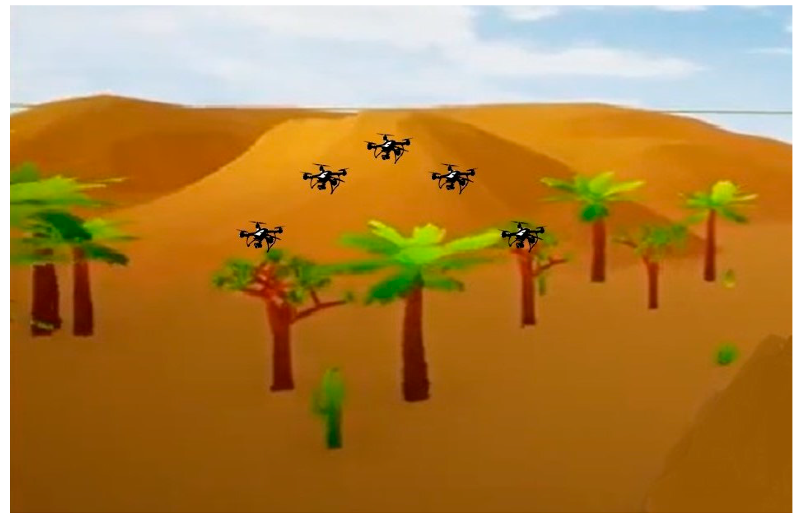
Figure 1. Mission area comprised of mountains.
Fractalfract 08 00334 g001
Figure 2. Mountain terrain cost.
Fractalfract 08 00334 g002
Figure 3. Leader–follower formation mode.
Fractalfract 08 00334 g003
Figure 4. Flowchart of FO_VPPSO.
Fractalfract 08 00334 g004
Figure 5. Adaptive beta factor plot.
Fractalfract 08 00334 g005
Figure 6. Graphical demonstration of process.
Fractalfract 08 00334 g006
Figure 7. XYZ-axis plot of trajectories.
Fractalfract 08 00334 g007
Figure 8. XZ-axes of trajectories.
Fractalfract 08 00334 g008
Figure 9. YZ-axes plot of trajectories.
Fractalfract 08 00334 g009
Figure 10. Fitness graph of all UAVs (FOVPPSO).
Fractalfract 08 00334 g010
Figure 11. Fitness graph of all UAVs (VPPSO).
Fractalfract 08 00334 g011
Figure 12. Dynamic obstacle movements (trajectories).
Fractalfract 08 00334 g012
Figure 13. Path deviation concept.
Fractalfract 08 00334 g013
Figure 14. Path deviation of swarm.
Fractalfract 08 00334 g014
Figure 15. Path deviation for leader UAV (dynamic obstacle).
Fractalfract 08 00334 g015
Figure 16. Convergence behaviors of all UAVS (FOVPPSO).
Fractalfract 08 00334 g016
Figure 17. Convergence behaviors of all UAVs (VPPSO).
Fractalfract 08 00334 g017
Table 1. Performance comparison with uni- and multimodal benchmark functions.
FunctionsDimMFO [42]PSO [42]GSA [42]BA [42]FOVPPSO
MeanSTDMeanSTDMeanSTDMeanSTDMeanSTD
  F 1 ( x ) = i = 1 n x i 2 1000.0001170.000151.321151.15388608.232464.65420792.45892.400.00310.0023
  F 2 ( x ) = i = 1 n x i + i = 1 n x i 1000.0006390.0008777.715564.1321222.75263.3651389.78541.95770.00420.0017
  F 3 ( x ) = i = 1 n j 1 i x j 2 100696.730188.527736.393361.781135760.48652.662481.329769.11.4110 × 1031.5645 × 103
  F 4 ( x ) = m a x i x i , 1 i n 10070.68645.2750512.97282.6344378.78192.8141049.743210.1436333.900410.2286
  F 5 ( x ) = i = 1 n 1 100 x i + 1 x i 2 2 + x i 1 2 100139.148120.26077,360.8351156.15741.003781.2393199,512125,238112.1192182.9603
  F 6 ( x ) = i = 1 n x i + 0.5 2 1000.000119.87 × 10−5286.651107.0793080.96898.63517,053.44917.560.00320.0021
  F 7 ( x ) = i = 1 n i x i 4 + r a n d o m   [ 0,1 ) 1000.0911550.046421.0373160.3103150.1129750.0376076.0450553.0452770.02090.0065
  F 8 ( x ) = i = 1 n x i s i n   x i 1008496.78725.8737−3571430.7989−2352.32382.167655350−9.4068 × 103545.8885
  F 9 ( x ) = i = 1 n x i 2 10 c o s   2 π x i + 10 10084.60016.1665124.2914.250931.000113.660596.215219.587573.439124.2290
  F 10 ( x ) = 20 e x p   0.2 1 n i = 1 n x i 2 e x p   1 n i = 1 n c o s   2 π x i + 20 + e 1001.26030.729569.16791.568983.740980.1712615.94600.774950.10780.4614
  F 11 ( x ) = 1 4000 i = 1 n x i 2 i = 1 n c o s   x i i + 1 1000.01900.0217312.4184.165830.049780.04978220.28154.70660.01810.0151
  F 12 ( x ) 1000.8940060.8812713.873785.853730.463440.13759828,934,3542,178,6830.57110.6499
  F 13 ( x ) 1000.1158240.19304211,813.530,701.97.6171141.225321.09 × 1081.05 × 1080.06160.2539
FunctionsDimFPA [42]SMS [42]FA [42]GA [42]FOVPPSO
MeanSTDMeanSTDMeanSTDMeanSTDMeanSTD
  F 1 ( x ) = i = 1 n x i 2 100203.63878.398412007480.74894.84921886.02879.580.00310.0023
  F 2 ( x ) = i = 1 n x i + i = 1 n x i 10011.16872.919590.02050.0047139.32532.4658656.51755.660850.00420.0017
  F 3 ( x ) = i = 1 n j 1 i x j 2 100237.56136.646337820017,357.31740.1137,010.25572.211.4110 × 1031.5645 × 103
  F 4 ( x ) = m a x i x i , 1 i n 10012.572842.2969.17003.8766633.95351.8696659.143314.64852633.900410.2286
  F 5 ( x ) = i = 1 n 1 100 x i + 1 x i 2 2 + x i 1 2 10010974.12,057.2638,224729,9673,795,009759,0303,132,1415,264,496112.1192182.9603
  F 6 ( x ) = i = 1 n x i + 0.5 2 100175.3863.452541439.3295.237828.72975.21020,964.83868.100.00320.0021
  F 7 ( x ) = i = 1 n i x i 4 + r a n d o m   [ 0,1 ) 1000.135940.0612120.049520.0240151.9063130.46005613.375043.081490.02090.0065
  F 8 ( x ) = i = 1 n x i s i n   x i 100−8086.74155.346−3942.82404.160−3662.05214.163−6331.19332.566−9.4068 × 103545.8885
  F 9 ( x ) = i = 1 n x i 2 10 c o s   2 π x i + 10 10092.691714.2239152.84418.5535214.89517.2191236.8219.0335973.439124.2290
  F 10 ( x ) = 20 e x p   0.2 1 n i = 1 n x i 2 e x p   1 n i = 1 n c o s   2 π x i + 20 + e 1006.844831.2499819.13250.2385214.56760.4675117.84610.531140.10780.4614
  F 11 ( x ) = 1 4000 i = 1 n x i 2 i = 1 n c o s   x i i + 1 1002.71600.72771420.52525.2561269.6575512.11393179.904632.439560.01810.0151
  F 12 ( x ) 1004.1053391.0434928,742,8141,405,679368,400.8172,132.934,131,6821,893,4290.57110.6499
  F 13 ( x ) 10062.398594.842981 × 10805,557,6611,689,9951.08 × 1083,849,7480.06160.2539
Table 2. Parametric constraints for mountainous terrain.
Sr. #1st Peak2nd Peak3rd Peak4th Peak5th Peak6th Peak
Altitude (km)0.511.75112
Centre positions (x, y)(10, 10)(20, 20)(30, 30)(20, 5)(30, 15)(10, 30)
Slope decrease (x-axis)224224
Slope decrease (y-axis)224244
Table 3. Flight coordinates for all UAVs.
Sr. #Leader UAV1st UAV2nd UAV3rd UAV4th UAV5th UAV6th UAV7th UAV8th UAV
Start point (x, y)(0, 10, 0)(0, 12, 0)(0, 8, 0)(0, 14, 0)(0, 6, 0)(0, 16, 0)(0, 4, 0)(0, 18, 0)(0, 2, 0)
End point (x, y)(30, 22, 3.2)(25, 22, 2.5)(25, 18, 2.5)(25, 24, 2.5)(25, 16, 2.5)(25, 26, 2.5)(25, 14, 2.5)(25, 28, 2.5)(25, 12, 2.5)
Table 4. Constraints of static obstacles.
1st Obstacle2nd Obstacle3rd Obstacle
Position (x, y, z)(8, 15, 2)(15, 10, 3)(20, 20, 2.5)
Obstacle radii 222
Table 5. Constraints of dynamic obstacle.
Dynamic Obstacle
Position (x, y)(10, 10)
Obstacle velocity(0.05, 0.05)
Time0.5
Table 6. Comparison of performance index and net percentage improvement by FOVPPSO.
Objective FunctionTotal Flight LengthMountain Terrain CostCollision AvoidanceFOVPPSO to PSOFOVPPSO to VPPSO
Minimum flight length213.1238 km8.85040.925329.05%2.26%
Mountain terrain cost154.6367 km7.51530.597116.46%1.60%
Collision avoidance cost151.152 km7.39540.408255.88%31.63%
Disclaimer/Publisher’s Note: The statements, opinions and data contained in all publications are solely those of the individual author(s) and contributor(s) and not of MDPI and/or the editor(s). MDPI and/or the editor(s) disclaim responsibility for any injury to people or property resulting from any ideas, methods, instructions or products referred to in the content.