Article

Dynamic Analysis and Sliding Mode Synchronization Control of Chaotic Systems with Conditional Symmetric Fractional-Order Memristors

1
Xi’an Key Laboratory of Human-Machine Integration and Control Technology for Intelligent Rehabilitation, School of Computer Science, Xijing University, Xi’an 710123, China
2
Shaanxi International Joint Research Center for Applied Technology of Controllable Neutron Source, School of Electronic Information, Xijing University, Xi’an 710123, China
3
College of Mathematics and Big Data, Guizhou Education University, Guiyang 550018, China
4
School of Mathematics and Computer Science, Yan’an University, Yan’an 716000, China
*
Author to whom correspondence should be addressed.
Fractal Fract. 2024, 8(6), 307; https://doi.org/10.3390/fractalfract8060307
Submission received: 9 April 2024 / Revised: 12 May 2024 / Accepted: 20 May 2024 / Published: 23 May 2024

Abstract

:
In this paper, the characteristics of absolute value memristors are verified through the circuit implementation and construction of a chaotic system with a conditional symmetric fractional-order memristor. The dynamic behavior of fractional-order memristor systems is explored using fractional-order calculus theory and the Adomian Decomposition Method (ADM). Concurrently, the investigation probes into the existence of coexisting symmetric attractors, multiple coexisting bifurcation diagrams, and Lyapunov exponent spectra (LEs) utilizing system parameters as variables. Additionally, the system demonstrates an intriguing phenomenon known as offset boosting, where the embedding of an offset can adjust the position and size of the system’s attractors. To ensure the practical applicability of these findings, a fractional-order sliding mode synchronization control scheme, inspired by integer-order sliding mode theory, is designed. The rationality and feasibility of this scheme are validated through a theoretical analysis and numerical simulation.

1. Introduction

Similar to a resistor, a capacitor, and an inductor, a memristor is defined as a nonvolatile nonlinear circuit element [1]. At the moment, memristor research is mostly focused on physical device preparation, characteristic analysis, and application research [2,3,4,5,6]. Furthermore, because of the limitations of its manufacturing method, the memristor has not been extensively industrialized. At the same time, different types of memristors have different switching mechanisms, resulting in significant variances in electrical performance. Therefore, designing mathematical models to study the electrical characteristics, nonlinear dynamics, and control of memristors for systematic analysis has aroused great interest among scholars. In 2008, Strukov and others from HP Laboratories confirmed the existence of memristors. Itoh and others proposed a piecewise linear model of the monotonic rise of a memristor and used this model to propose and design the first memristor chaotic system, proving that a memristor can replace Chua’s diode in the design of chaotic circuits [7]. In 2009, Muthuswamy et al. replaced Chua’s diode in Chua’s circuit with the newly designed piecewise linear model of a memristor and analyzed in detail the dynamic characteristics of the replaced memristor-type chaotic system [8]. Subsequently, they introduced a smooth magnetically controlled triple memristor into Chua’s circuit, which can generate a double-scroll chaotic attractor [9]. Bao developed a memristor model based on Chua’s circuit and conducted a detailed analysis of the dynamic characteristics of these systems. The findings revealed that the dynamic behavior of chaotic circuits incorporating memristors is intricately linked to the system parameters and the initial conditions [10]. At the same time, Wang identified various complex chaotic phenomena within these systems, such as extreme multistability, transient chaos, state transitions, and chaotic explosions [11,12,13]. In addition, researchers have also carried out a lot of work on the application of memristors in the double T-shaped oscillator, the Venn oscillator, and the classical Lorenz and Jerk chaotic systems, and they have obtained memristor chaotic attractors with different states [14,15,16]. To sum up, by utilizing the memory characteristics of memristors to establish a memristor-based chaotic circuit system, the original circuit can exhibit richer dynamical behaviors, offering enhanced flexibility for practical engineering applications such as digital logic circuits and neural networks.
However, due to the constraints inherent in the definition of an integer derivative, it fails to capture the memory properties of viscous substances. In contrast, the definition of a fractional derivative includes convolutional components, which effectively represent the memory effect and the accumulation of effects over time [17]. Research on memristors has shown that its nonvolatility is consistent with the memory characteristics described by the fractional derivative, which can also provide an important feature for memristor system modeling [18]. Compared with integer-order memristor systems, in addition to the chaotic characteristics caused by nonlinearity in fractional-order memristor systems, the multistability caused by their memory characteristics has also attracted great interest, such as the stability, multi-stability, and bifurcation of fractional-order memristor systems [19], the coexistence of a singular attractor in fractional-order memristor systems [20], chaotic and hyperchaotic behaviors in fractional-order memristor systems [21,22,23], and so on. However, it has been recognized that identifying the behavior of coexisting attractors within a system is crucial, particularly by establishing conditional symmetry to overcome the limitations inherent in the original system structure. This approach enables the generation of coexisting attractors in asymmetric systems [24,25], which can somewhat simplify the complexity of the system’s solutions.
Since Pecora and Carroll introduced the concept of chaotic system synchronization [26], numerous scholars have developed various synchronization strategies for such systems. These include sliding mode control, pulse synchronization, adaptive synchronization, and other control schemes [27,28,29,30,31,32]. In 2005, Alasty et al. used continuous-time dynamic systems as an example to illustrate the control of chaos in a fuzzy estimation system based on batch training and the recursive least squares method. The fuzzy estimator system used the Ott, Grebogi, and Yorke (OGY) control algorithm and the delayed feedback control algorithm [33]. In 2009, Feki used the sliding mode control theory to propose a new sliding mode controller, which proved that for a class of chaotic systems that can be stabilized by a smooth feedback controller, it is easy to construct a sliding manifold using the Lyapunov function, and the author designed an adaptive sliding controller [34]. In 2019, Hu Yueli et al. used new methods to study time-delay chaotic systems based on the nonlinear dynamic characteristics of chaotic systems and the stability principles of time-delay systems, designed feasible linear controllers, and achieved a time-delay chaotic control and synchronization of Lorenz systems [35]. With the development and refinement of fractional calculus theory, fractional-order control theory has demonstrated its superiority in system modeling and control. Due to the hereditary and memory properties of fractional calculus operators, fractional-order controllers exhibit better robustness and flexibility compared to integer-order controllers. Examples include the active sliding mode control scheme for synchronizing fractional-order chaotic systems [36], the adaptive anti-synchronization fractional-order sliding mode control scheme [37], the fractional-order adaptive continuous sliding mode synchronization control under unknown control gains [38], and chaos and projective synchronization based on fuzzy state feedback control [39]. Therefore, for the fractional-order memristor chaotic system discussed in this paper, we combined sliding mode control theory with fractional calculus to propose a fractional-order sliding mode synchronization control strategy. This not only eliminates the restrictions imposed by non-integer-order controllers on the order of the controlled system but also increases the variability of the order compared to integer-order controllers, thereby endowing the system with unique performance.
This paper’s structure is as follows: in Section 2, the hysteresis loop of an absolute memristor is implemented using an analog circuit and validated through a numerical simulation analysis. In addition, a conditionally symmetric fractional-order memristor chaotic system model is constructed using the memristor, and the system is further decomposed using the ADM algorithm. In Section 3, the coexistence of complex dynamic phenomena and conditional symmetry caused by changes in the order and system parameters of fractional-order memristor systems are explored. This section concludes with a discussion on the unique offset boosting phenomenon of fractional-order memristor systems. In Section 4, a sliding mode fractional-order synchronization control scheme is implemented. Section 5 summarizes the work presented in this paper and outlines potential directions for future work.

2. Conditionally Symmetric Fractional-Order Memristor Chaotic System

2.1. System Modeling

A memristor is a two-terminal circuit element described by the equation f ( φ , q ) = 0 , and the mathematical model of a smooth, continuous quadratic nonlinear magnetic-controlled memristor is given by q ( φ ) = α φ + 0.5 β | φ | φ . Therefore, we can introduce a nonlinear absolute value-type memristor. The description is as follows:
i = W φ v W φ = α + β φ
where W φ represents the memductance, i is the output current, v is the input voltage, α and β are system parameters, and φ is a state variable. By taking the values of the parameters in Equation (1) as α = 0.1 , β = 0.3 , the circuit schematic diagram of the absolute value memristor is shown in Figure 1.
According to the circuit schematic diagram of an absolute value memristor shown in Figure 1, the following circuit equation can be derived:
i t = v t R 3 R 2 R 5 R 4 R 8 R 6 + v t R 3 R 2 R 8 R 7 v t
where i t represents the output current value, v t represents the output voltage value, and the absolute value circuit outputs the voltage v t . Based on the schematic of the equivalent analog circuit for an absolute value memristor, an external input voltage v = V s i n ( 2 π f ) is applied to both ends of the absolute value-type memristor. In Multisim simulations, with a varying amplitude V and frequency f of the excitation voltage, the memristor displays a tight hysteresis loop at the origin of the voltage–current plane. The area of the hysteresis loop positively correlates with the amplitude V and negatively correlates with the frequency f. The simulation results showing changes in the hysteresis loop area as reflected by the absolute value memristor circuit are illustrated in Figure 2.
To further validate the simulation results of the absolute value-type memristor analog circuit, MATLAB numerical simulations were conducted by adjusting the amplitude V and frequency f of the external excitation signal, as shown in Figure 3. Consistent with the Multisim simulations shown in Figure 2, it is observed that the area of the hysteresis loop increases with the increase in amplitude V but decreases with the increase in frequency f.
By establishing and analyzing the absolute value-type memristor mentioned above, we introduced Equation (1) based on the system described in [40]. This forms the basis for establishing a class of conditionally symmetric fractional-order memristor chaotic systems:
D t 0 q x 1 = 1 a x 2 x 3 D t 0 q x 2 = x 3 | x 3 | x 3 D t 0 q x 3 = F ( x 1 ) W ( x 4 ) x 3 D t 0 q x 4 = | x 3 | b x 4
where D t 0 q is a continuous integral differential operator, t 0 is the lower limit of fractional calculus operation, q R , F x 1 = ( | x 1 | c ) , and W x 4 = α + β x 4 .

2.2. ADM of the System

General fractional-order chaotic systems D t q x ( t ) = f ( x ( t ) ) + g ( t ) , where x ( t ) = x 1 t , x 2 t , x n ( t ) ] T is the functional variable of the system, while g ( t ) = g 1 , g 2 , , g n T is the constant of the autonomous system, where f includes the linear and nonlinear parts of the system, can be decomposed as follows:
D t 0 q x t = L x + N x + g t x k t 0 + = b k , k = 0 , 1 , , m 1 m N , m 1 < q < m
where D t 0 q is a Caputo differential operator of order q, L represents the linear term of the system, N represents the nonlinear term of the system, and b k is the initial value. Using the integral operator J on both ends of Equation (4) J t 0 q can obtain the following:
x = J t 0 q L x + J t 0 q N x + Φ
In Equation (5), Φ = k = 0 m 1 b k ( t t 0 ) k k ! , and the linear, nonlinear, and constant terms of the system in Equation (3) are delineated as follows:
L x 1 L x 2 L x 3 L x 4 = 1 x 3 x 1 c + α x 3 | x 3 | b x 4 , N x 1 N x 2 N x 3 N x 4 = a x 2 x 3 x 3 | x 3 | x 3 | x 4 | 0 , g 1 g 2 g 3 g 4 = 0 0 0 0
The detailed ADM process is provided in Appendix A. The numerical solution of the system in Equation (3) is obtained through the ADM as follows:
x ˜ j t = c j 0 + c j 1 t t 0 q Γ q + 1 + c j 2 t t 0 2 q Γ 2 q + 1 + c j 3 t t 0 3 q Γ 3 q + 1 + c j 4 t t 0 4 q Γ 4 q + 1
and the ADM shows that when the parameter selection for the system in Equation (3) is a = 3.55 , b = 0.8 , c = 3 , α = 0.1 , β = 0.3 , and q = 0.90 and the initial value is (3, 0, 1, 0.1), the system shows a complex and rich chaotic attractor as shown in Figure 4.

3. Analysis of Dynamic Characteristics

3.1. Symmetry Analysis

Considering the system in Equation (3), assuming the occurrence of the transformation ( x 1 , x 2 , x 3 , x 4 ) ( x 1 , x 2 , x 3 , x 4 ) , it can be easily observed that if the system produces symmetry, the system in Equation (3) must satisfy the condition F x 1 = x 1 c = x 1 c to behave as a symmetric fractional resistive chaotic system. At this point, this indicates that parameter c in Equation (3) can be used as an adjustment parameter to achieve symmetry in the system. When the parameter c = 3 is randomly selected and the initial values are ( 3 , 0 , 1 , 0.1 ) and (−3, 0, −1, 0.1), respectively, it is found that the system in Equation (3) shows the symmetric coexistence chaotic attractor as shown in Figure 5.

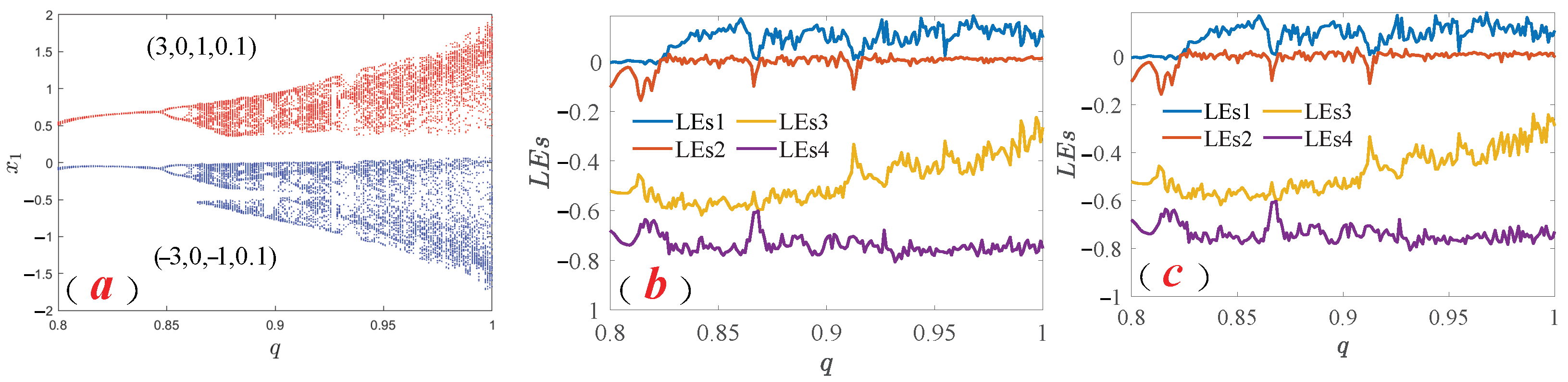
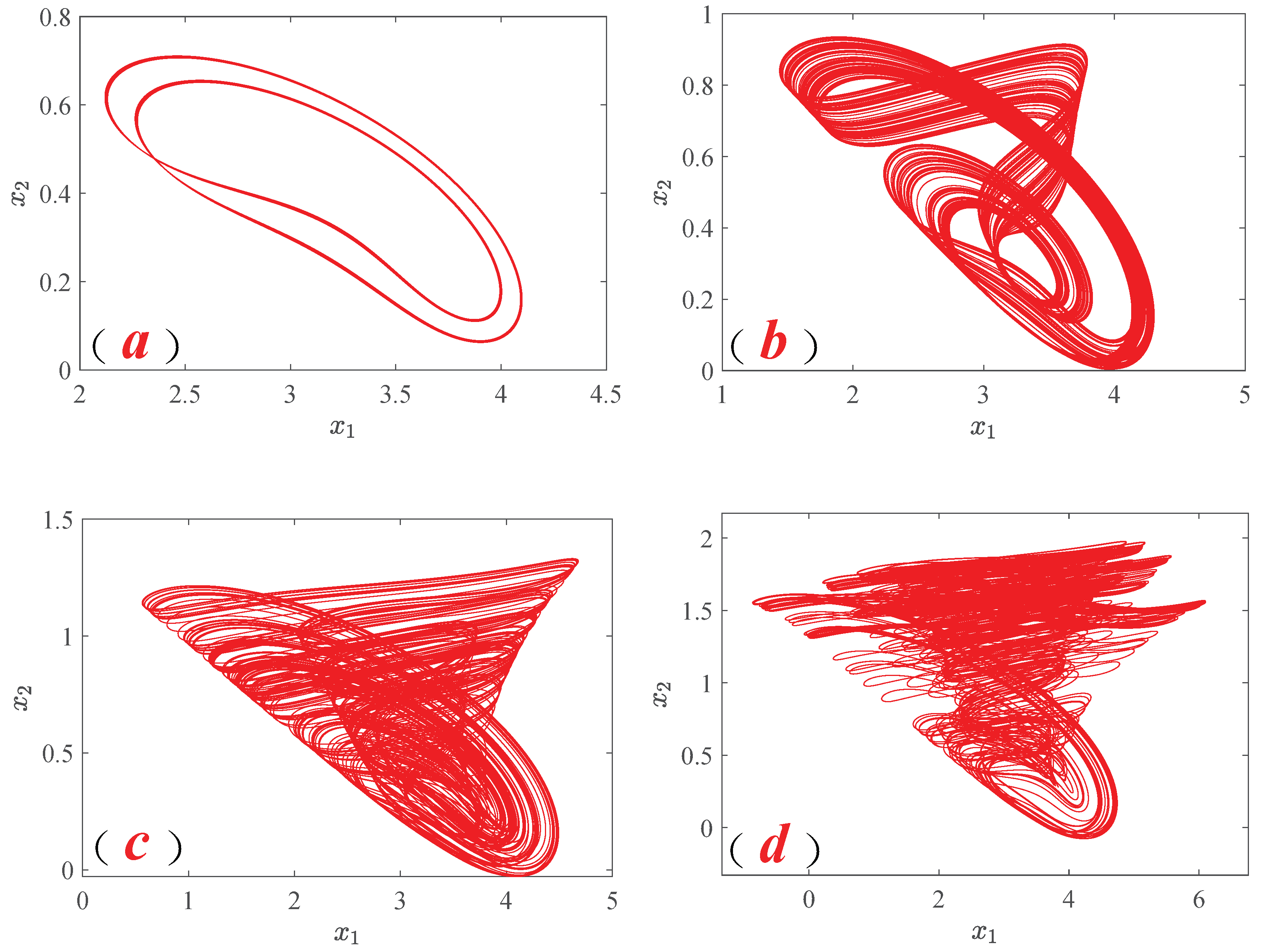
3.2. Coexistent Dynamic Behavior of System Orders Change

In order to illustrate the fractional-orders dynamic characteristics of the system in Equation (3), we choose to study the dynamic phenomena of order q changes, with a range of order changes of q ( 0.8 , 1 ) and parameters of a = 3.55 , b = 0.8 , c = 3 , α = 0.1 , and β = 0.3 , with initial values of ( 3 , 0 , 1 , 0.1 ) and ( 3 , 0 , 1 , 0.1 ) . In Figure 6, a coexistence bifurcation diagram with fractional-order q as the independent variable and LEs are plotted to investigate their impact on the dynamic phenomena of the system. In the coexistence bifurcation diagram of Figure 6a, under the conditions where the red path has an initial value of ( 3 , 0 , 1 , 0.1 ) and the blue coexistence bifurcation path has an initial value of ( 3 ,   0 , 1 , 0.1 ) , it can be observed that the bifurcation paths of the system enter the chaotic state as period doubling bifurcation, and the bifurcation diagrams of the two exist in a symmetrical co-existence form. Subsequently, it is found that the phases where the Largest Lyapunov Exponent (LLE) is greater than zero, as described in Figure 6b,c, are consistent with the chaotic states, indicating that the LEs results and the coexistence bifurcation diagram in Figure 6a reflect consistent dynamic results.
Then, by selecting the system in Equation (3) and taking different values of fractional orders q, we find that the system in Equation (3) shows different types of chaotic attractors, which further shows that this system has more abundant memristor chaotic attractors than the system in [41], as revealed by the numerical simulation results shown in Figure 7.

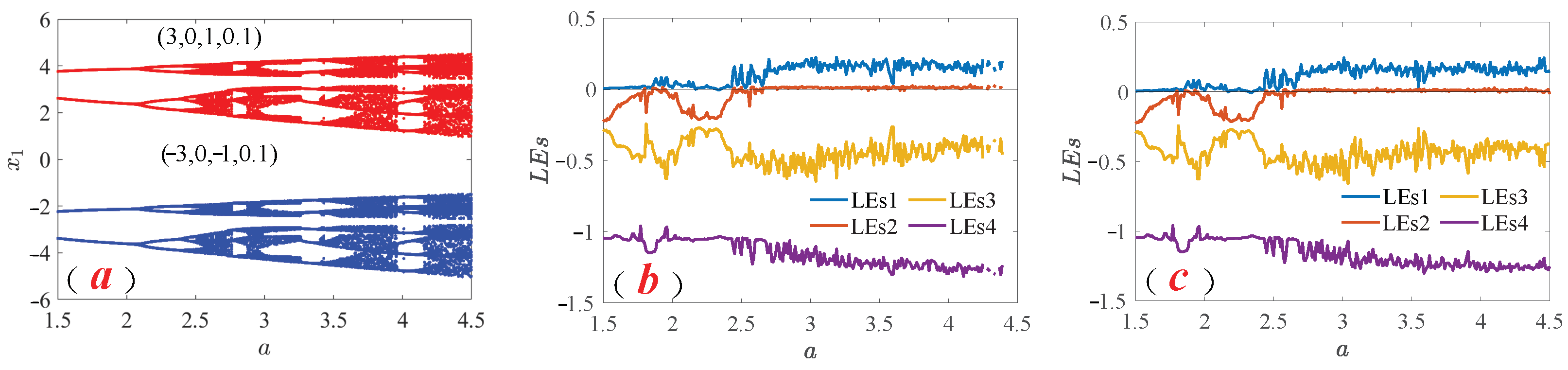
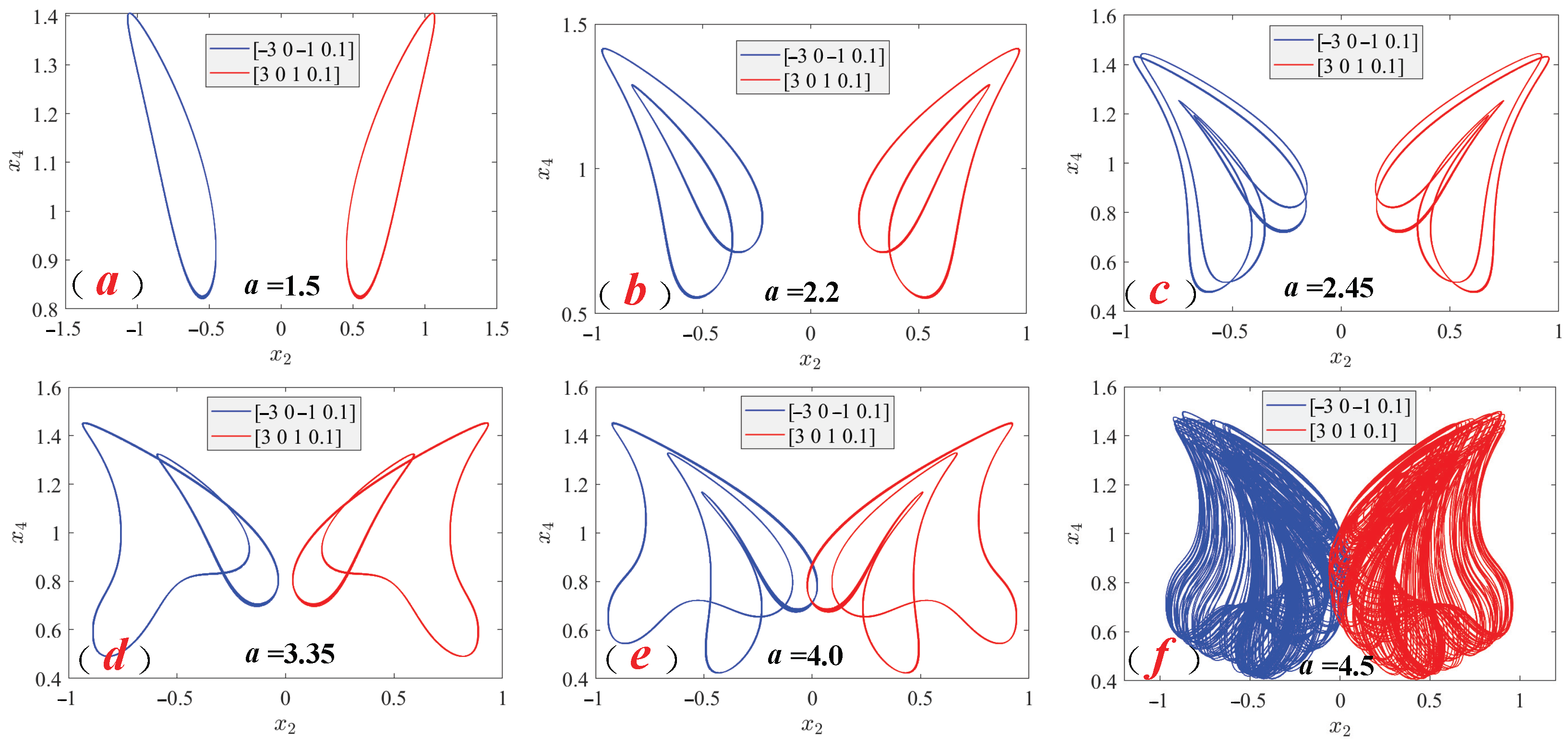
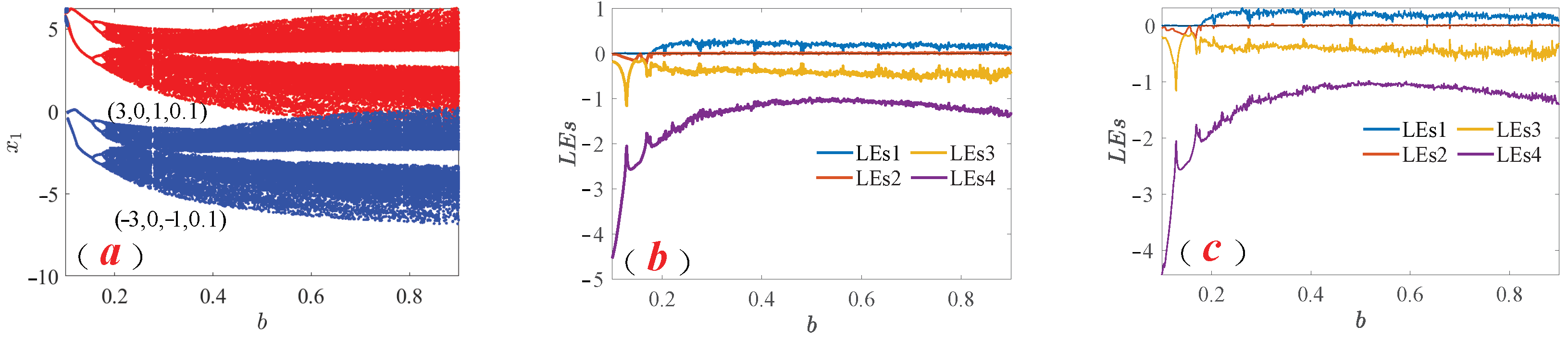
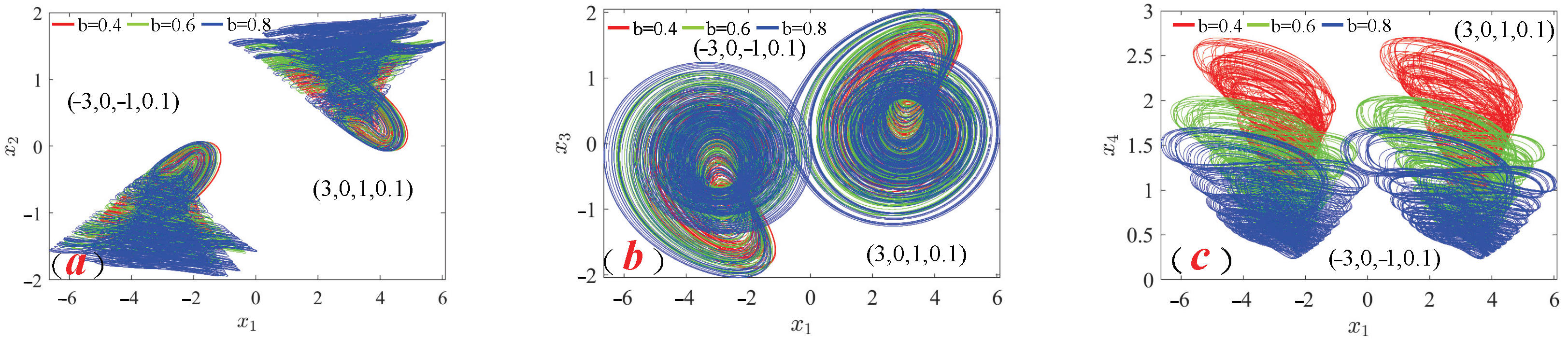
3.3. Coexistence Dynamics Behavior of System Parameter Changes

By revealing the dynamic behavior after fractional orders change, considering the parameter selection of the system in Equation (3) as b = 0.8 , c = 3 , α = 0.1 , β = 0.3 , and q = 0.90 with initial values of ( 3 , 0 , 1 , 0.1 ) and (−3, 0, −1, 0.1), respectively, the coexistence bifurcation diagram of the variation in parameter a ( 1.5 4.5 ) is plotted in Figure 8a. The red bifurcation curve describes the evolution of the system with a period-doubled bifurcation behavior under the initial value of ( 3 , 0 , 1 , 0.1 ) . Similarly, under the initial value of (−3, 0, −1, 0.1), the blue bifurcation curve in Figure 8a also describes the same bifurcation path change as before, but there is a clear symmetry phenomenon with the red bifurcation path. The LEs in Figure 8b,c are plotted while maintaining consistency between all parameter values and the analysis coexistence bifurcation diagram. The study shows that the LEs exhibit a similar dynamic behavior to the bifurcation diagram.
The selection of other parameters for the system in Equation (3) remains consistent with the above, only studying the type of system phase diagram that changes with parameter a. The type of symmetrical coexistence phase diagram attractor appearing on the bifurcation path when the parameter a of the system changes in the plane x 2 x 4 is described in detail in Figure 9.
Similarly, when selecting parameters a = 3.55 , c = 3 , α = 0.1 , β = 0.3 , and q = 0.90 , the initial value conditions are ( 3 , 0 , 1 , 0.1 ) and (−3, 0, −1, 0.1), respectively. When the parameter b ( 0.1 0.9 ) for the system in Equation (3), its coexistence bifurcation diagram and LEs are shown in Figure 10, respectively. Under two initial conditions ( 3 , 0 , 1 , 0.1 ) and (−3, 0, −1, 0.1), represented in red and blue, respectively, the bifurcation path in Figure 10a appears in a period-doubling manner. Further analyses of the coexistence bifurcation diagram and the LEs in Figure 10b,c reveal the same dynamic behavior.
But when parameter b changes, an interesting phenomenon is found. When the system in Equation (3) is in a chaotic state, it is found that adjusting parameter b can amplify or shrink the coexistence symmetric chaotic attractor of the system. That is, when the parameter b changes within a certain range, the size of the coexistence attractor is modified accordingly. As shown in Figure 11, the change in parameter b from b = 0.4 , 0.6 , 0.8 makes the chaotic attractor to be constantly amplified. The dynamic behavior of this interesting special fractional-order memristor chaotic system can provide flexible choices for engineering applications based on memristor chaos.

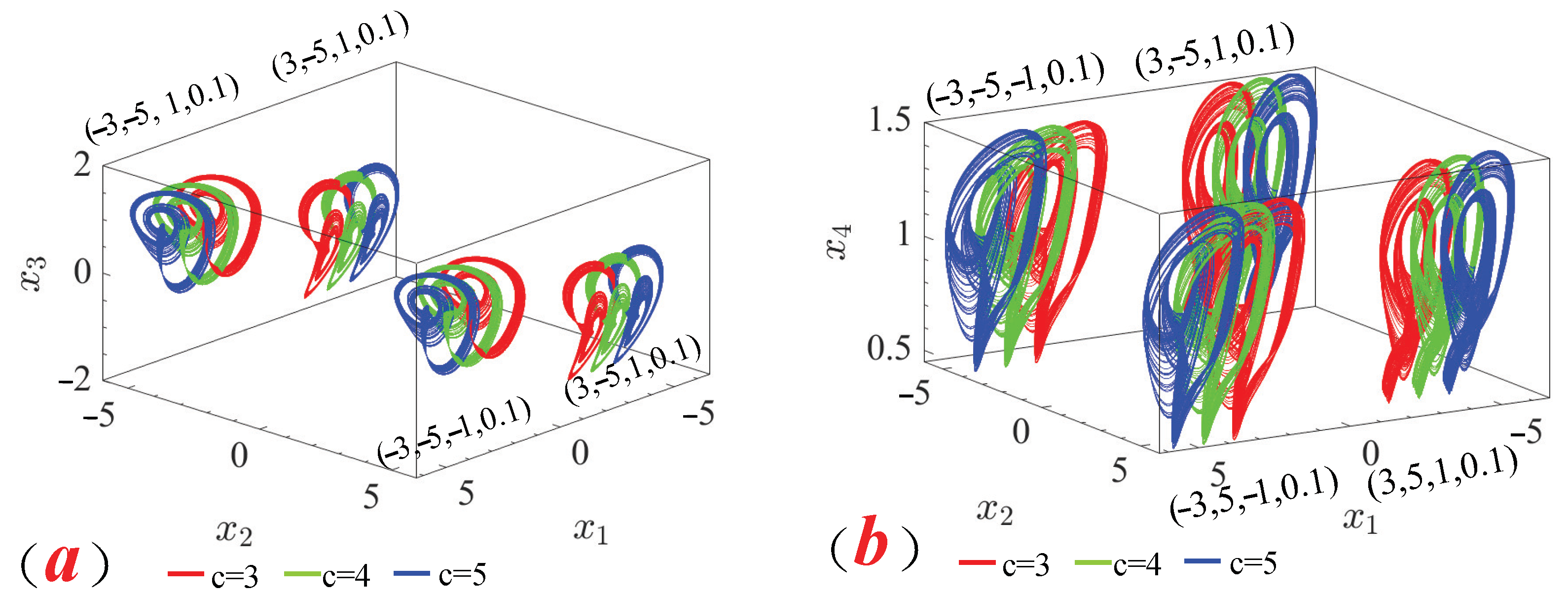
3.4. System Coexistence Offset Boosting Phenomenon

For the nonlinear system, the phenomenon of offset boosting is a movement process, and a constant is often used as the control quantity. By observing the system in Equation (3), it is found that the constant term of the variable x 2 does not change the dynamic behavior of the system, but it can change the position of the system’s attractor. Then, by adding the constant term p after the variable, the following Equation (8) can be obtained:
D t 0 q x 1 = 1 a ( x 2 p ) x 3 D t 0 q x 2 = x 3 | x 3 | x 3 D t 0 q x 3 = F ( x 1 ) W ( x 4 ) x 3 D t 0 q x 4 = | x 3 | b x 4
In order to reveal the offset boosting phenomenon of the system, the system parameter values were selected to be consistent with the above dynamic research, and the two initial values for symmetric coexistence were selected as (3, p, 1, 0.1) and (−3, p, −1, 0.1), respectively. By setting the offset p to −5, 0, and 5, respectively, it was found through a numerical simulation that the symmetric coexistence of chaotic attractors also appears at the offset p and does not change the dynamic behavior of the original system but only changes the position of its attractor through the offset p, as shown in Figure 12.
Similarly, in the research on the system in Equation (3), it was found that parameter c can cause an interesting offset boosting phenomenon. The other parameters were selected as a = 3.55 , b = 0.8 , d = ± 5 , α = 0.1 , β = 0.3 , and q = 0.90 , respectively. The change in the chaotic attractor position was studied by changing the system offset boosting parameter c to c = 3 , 4 , 5 , respectively. It can be found that when c > 3 , regardless of the influence factor of the parameter d, the distance between the two symmetrically coexisting attractors on the x 1 axis can be far from each other as c increases, as shown in Figure 13.

4. Fractional-Order Sliding Mode Synchronization

According to the nonlinear characteristics of the system, a reasonable sliding mode control law is designed and introduced into the system to change the trajectory of the system to reach the desired position.

4.1. Implementation of Fractional-Order Sliding Mode Synchronization Control

Based on Equation (3), we establish the following fractional-order master system:
D t 0 q x 1 = 1 a x 2 x 3 D t 0 q x 2 = x 3 | x 3 | x 3 D t 0 q x 3 = | x 1 | c ( α + β | x 4 | ) x 3 D t 0 q x 4 = | x 3 | b x 4
in which q ( 0 , 1 ) is the order of the fractional derivative.
In order to achieve the sliding mode synchronization of Equation (3), the fractional-order slave system is as follows:
D t 0 q x s 1 = 1 a x s 2 x s 3 + u 1 D t 0 q x s 2 = x s 3 | x s 3 | x s 3 + u 2 D t 0 q x s 3 = | x s 1 | c ( α + β | x s 4 | ) x s 3 + u 3 D t 0 q x s 4 = | x s 3 | b x s 4 + u 4
By further defining the error of the system as e 1 = x s 1 x 1 , e 2 = x s 2 x 2 , e 3 = x s 3 x 3 , and e 4 = x s 4 x 4 , the following dynamic equation for Equation (3)’s state error system is obtained:
D t 0 q e 1 = a x s 2 e 3 a x 3 e 2 + u 1 D t 0 q e 2 = x s 3 x s 3 x 3 x 3 e 3 + u 2 D t 0 q e 3 = x s 1 x 1 + α e 3 f ( x s 3 x s 4 x 3 | x 4 | ) + u 3 D t 0 q e 4 = x s 3 x 3 b e 4 + u 4
Design the sliding surface function as follows:
s 1 t = D t 0 q + λ 1 0 t e 1 τ d τ s 2 t = D t 0 q + λ 2 0 t e 2 τ d τ s 3 t = D t 0 q + λ 3 0 t e 3 τ d τ s 4 t = D t 0 q + λ 4 0 t e 4 τ d τ
Calculate the first derivative of the sliding surface function of Equation (12) to obtain the following:
s ˙ 1 t = D t 0 q e 1 t + λ 1 e 1 t s ˙ 2 t = D t 0 q e 2 t + λ 1 e 2 t s ˙ 3 t = D t 0 q e 2 t + λ 1 e 2 t s ˙ 4 t = D t 0 q e 2 t + λ 1 e 2 t
When the system in Equation (11) moves on the sliding mode surface in Equation (12) and satisfies the conditions s = 0 and s ˙ = 0 , the sliding mode dynamics equation is as follows:
D t 0 q e 1 t = λ 1 e 1 t D t 0 q e 2 t = λ 1 e 2 t D t 0 q e 3 t = λ 1 e 3 t D t 0 q e 4 t = λ 1 e 4 t
It is evident that the error state of Equation (14) gradually converges to zero.
Let the Lyapunov functions be
V 1 t = 1 2 s 1 2 V 2 t = 1 2 s 2 2 V 3 t = 1 2 s 3 2 V 4 t = 1 2 s 4 2
Choosing to calculate the first derivative of V i t ( i = 1 , 2 , 3 , 4 ) with respect to time yields
V 1 ˙ t = s 1 s ˙ 1 = s 1 D t 0 q e 1 + λ 1 e 1 V 2 ˙ t = s 2 s ˙ 2 = s 2 D t 0 q e 2 + λ 2 e 2 V 3 ˙ t = s 3 s ˙ 3 = s 3 D t 0 q e 3 + λ 3 e 3 V 4 ˙ t = s 4 s ˙ 4 = s 4 D t 0 q e 4 + λ 4 e 4
By substituting Equation (11) into Equation (16), it can be concluded that
V 1 ˙ t = s 1 ( a x s 2 e 3 a x 3 e 2 + u 1 + λ 1 e 1 ) V 2 ˙ t = s 2 x s 3 x s 3 x 3 x 3 e 3 + u 2 + λ 2 e 2 V 3 ˙ t = s 3 x s 1 x 1 + α e 3 f ( x s 3 x s 4 x 3 | x 4 | ) + u 3 + λ 3 e 3 V 4 ˙ t = s 4 x s 3 x 3 b e 4 + u 4 + λ 4 e 4
Theorem 1.
Considering the fractional-order memristor chaotic circuit system (3), under the influence of the controller,
u 1 = a x s 2 e 3 + a x 3 e 2 λ 1 e 1 k 1 sign s 1 u 2 = x s 3 x s 3 + x 3 x 3 + e 3 λ 2 e 2 k 2 sign s 2 u 3 = x s 1 + x 1 α e 3 + f x s 3 x s 4 x 3 x 4 λ 3 e 3 k 3 sign s 3 u 4 = x s 3 + x 3 + b e 4 λ 4 e 4 k 4 sign s 4
the system state trajectories can reach the sliding surface within a finite time, meaning that the approaching phase of the sliding mode control process converges in finite time.
Proof. 
Substituting Equation (18) into Equation (17), it can be concluded that
V 1 ˙ t = k 1 s 1 V 2 ˙ t = k 2 s 2 V 3 ˙ t = k 3 s 3 V 4 ˙ t = k 4 s 4
then, select the Lyapunov function as
V s 1 , s 2 , s 3 , s 4 = 1 2 s 1 2 + 1 2 s 2 2 + 1 2 s 3 2 + 1 2 s 4 2
Take the derivative of Equation (20), and according to Equation (19), it can be concluded that
V ˙ s 1 , s 2 , s 3 , s 4 = k 1 s 1 + k 2 s 2 + k 3 s 3 + k 4 s 4
by selecting an appropriate value for parameter k, the relationship in Equation (22) holds.
k 1 s 1 + k 2 s 2 + k 3 s 3 + k 4 s 4 > k s
In Equation (22), s = s 1 2 + s 2 2 + s 3 2 + s 4 2 .
Therefore, according to Equation (21), it can be concluded that
V ˙ s 1 , s 2 , s 3 , s 4 < k s
The proof is finished. □

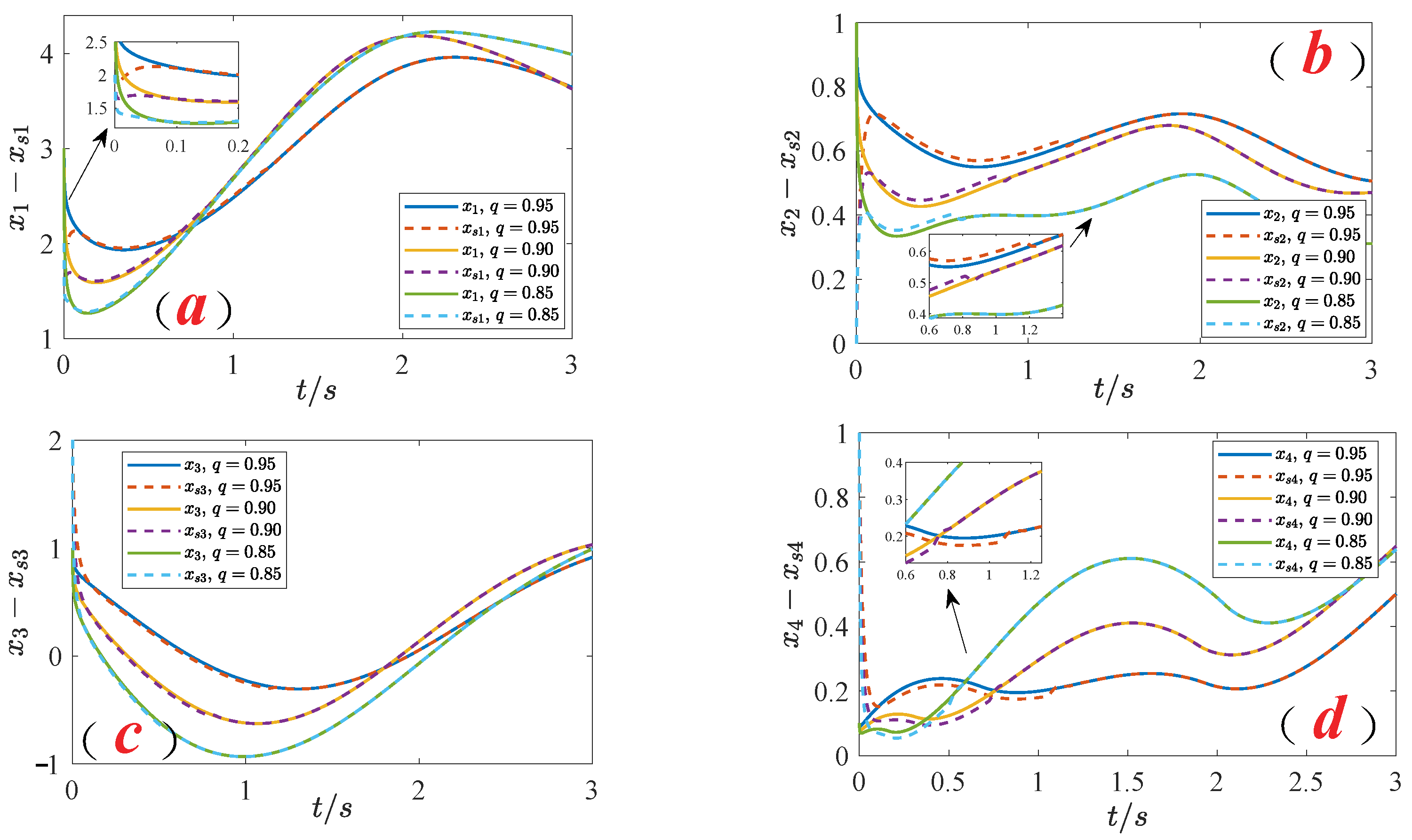
4.2. Numerical Simulation Results

In the numerical simulation of the fractional-order sliding mode synchronization control scheme established for the system in Equation (3), the system parameters are set as a = 3.55 , b = 0.8 , c = 3 , α = 0.1 , and β = 0.3 . The initial values for the master system are set to ( 0.1 , 0.1 , 0.1 , 0.1 ) , and those for the slave system are set to ( 4 , 3 , 2 , 1 ) . Further, we select the gains in the control law as k 1 = k 2 = k 3 = k 4 = 30 and the parameters in the fractional-order sliding mode surface as λ 1 = λ 2 = λ 3 = λ 4 = 0.8 . As the system order q changes, the fractional-order sliding mode synchronization diagram, as shown in Figure 14, indicates that lower orders converge faster, and the fractional-order integral sliding mode controller exhibits superior control performance. The variability of the orders provides it with unique capabilities. Concurrently, the sliding mode surface motion behavior of the system, as shown in Figure 15, reveals through numerical simulation that the fractional-order system’s sliding mode surface motion curve demonstrates a rapid convergence of the sliding mode synchronization control scheme, further validating the correctness of the fractional-order sliding mode control scheme.

5. Conclusions

In this paper, we construct a conditionally symmetric fractional-order memristor chaotic circuit system. Using the ADM, we explore various phase diagrams, coexisting bifurcation diagrams, LLE, and LEs. The introduction of fractional orders enriches the system’s dynamic behaviors and enhances the complexity of chaotic pseudo-random sequences, allowing for a more accurate description of circuit systems and providing a theoretical basis for practical engineering applications such as image processing and communication systems. Additionally, this paper reveals an interesting phenomenon known as offset boosting, which adjusts the position and size of the symmetric coexisting attractors through the offset term, demonstrating a special form of multistability. Finally, we propose a fractional-order sliding mode synchronization control scheme that remedies the deficiencies of integer-order systems in rounding orders and achieves rapid convergence. Despite this, from building memristor circuits and designing controllers to implementing fractional-order memristor chaotic control circuits and their applications in secure communications, we still face many fundamental and technical challenges that need to be addressed in the future.

Author Contributions

Software, M.Z.; Validation, H.T. and Z.W.; Formal analysis, J.L.; Investigation, Q.W. and X.Y.; Writing—original draft, H.T.; writing—review and editing, Z.W.; Supervision, Z.W. All authors have read and agreed to the published version of the manuscript.

Funding

This study was supported by the Scientific Research Program Funded by Education Department of Shaanxi Provincial Government (23JK0706), the Scientific Research Foundation of Xijing University (XJ230108, XJ21B01), the National Natural Science Foundation of China (22278338, 12172281), the Natural Science Basic Research Program of Shaanxi (2024JC-YBMS-064), the Fund of the Science and Technology Innovation Team of Shaanxi (2022TD-61), the Horizontal Project (2024610002002867), the Support Plan for Sanqin Scholars Innovation Team in Shaanxi Province of China, and the Fund of the Youth Innovation Team of Shaanxi Universities.

Data Availability Statement

Data are contained within the article.

Acknowledgments

The authors acknowledge the referees and the editor for carefully reading this paper and giving many helpful comments. The authors also express their gratitude to the reviewers for their insightful comments.

Conflicts of Interest

The authors declare no conflicts of interest.

Abbreviations

The following abbreviations are used in this manuscript:
ADMAdomian Decomposition Method
LEsLyapunov Exponent spectra
OGY controlOtt, Grebogi, and Yorke control
LLELargest Lyapunov Exponent

Appendix A

Regarding the decomposition of the nonlinear term x 1 x 2 in Equation (6), we represent the previous five items as examples:
A 1 0 = x 2 0 x 3 0 A 1 1 = x 2 1 x 3 0 + x 2 0 x 3 1 A 1 2 = x 2 2 x 3 0 + x 2 1 x 3 1 + x 2 0 x 3 2 A 1 3 = x 2 3 x 3 0 + x 2 2 x 3 1 + x 2 1 x 3 2 + x 2 0 x 3 3 A 1 4 = x 2 4 x 3 0 + x 2 3 x 3 1 + x 2 1 x 3 3 + x 2 2 x 3 2 + x 2 0 x 3 4
We further investigate the nonlinear term x 3 | x 3 | decomposition, also represented by the previous five items as examples:
A 2 0 = x 3 0 x 3 0 A 2 1 = x 3 1 x 3 0 + s i g n ( x 3 0 x 3 1 ) A 2 2 = x 3 2 x 3 0 + x 3 1 s i g n x 3 1 + x 3 0 s i g n x 3 2 A 2 3 = x 3 3 x 3 0 + x 3 2 s i g n x 3 1 + x 3 1 s i g n x 3 2 + x 3 0 s i g n x 3 3 A 2 4 = x 3 4 x 3 0 + x 3 3 s i g n x 3 1 + x 3 1 s i g n x 3 3 + x 3 2 s i g n x 3 2 + x 3 0 s i g n x 3 4
For the nonlinear term x 3 | x 4 | , a similar decomposition can be obtained according to Equation (A2). Assuming the initial values are x 0 = [ x 1 ( t 0 ) , x 2 ( t 0 ) , x 3 ( t 0 ) , x 4 ( t 0 ) ] , the first decomposition coefficient is as follows:
x 1 0 = x 1 t 0 x 2 0 = x 2 t 0 x 3 0 = x 3 t 0 x 4 0 = x 4 t 0
Let c 1 0 = x 1 0 , c 2 0 = x 2 0 , c 3 0 = x 3 0 , c 4 0 = x 4 0 , we can obtain x 0 = c 0 = [ c 1 0 , c 2 0 , c 3 0 , c 4 0 ] . According to the derivation of Equation (5), the second decomposition coefficient is as follows:
x 1 1 = 1 a x 2 0 x 3 0 t t 0 q Γ q + 1 x 2 1 = ( x 3 0 x 3 0 x 3 0 ) t t 0 q Γ q + 1 x 3 1 = ( x 1 0 c + α x 3 0 β x 3 0 x 4 0 ) t t 0 q Γ q + 1 x 4 1 = ( x 3 0 b x 4 0 ) t t 0 q Γ q + 1
The decomposition coefficient of the system holds:
c 1 1 = 1 a c 2 0 c 3 0 c 2 1 = c 3 0 c 3 0 c 3 0 c 3 1 = c 1 0 c + α c 3 0 β c 3 0 c 4 0 c 4 1 = c 3 0 b c 4 0
c 1 2 = 1 a ( c 2 1 c 3 0 + c 2 0 c 3 1 ) c 2 2 = c 3 1 c 3 0 + c 3 0 s i g n ( c 3 1 ) c 3 1 c 3 2 = s i g n ( c 1 1 ) c + α c 3 1 β ( c 3 1 c 4 0 + c 3 0 s i g n ( c 4 1 ) ) c 4 2 = s i g n ( c 3 1 ) b c 4 1
c 1 3 = 1 a ( c 2 2 c 3 0 + c 2 1 c 3 1 Γ 2 q + 1 Γ 2 q + 1 + c 2 0 c 3 2 ) c 2 3 = c 3 2 c 3 0 + c 3 1 s i g n c 3 1 Γ 2 q + 1 Γ 2 q + 1 + c 3 0 s i g n ( c 3 2 ) c 3 2 c 3 3 = s i g n ( c 1 2 ) c + α c 3 2 β ( c 3 2 c 4 0 + c 3 1 s i g n c 4 1 Γ 2 q + 1 Γ 2 q + 1 + c 3 0 s i g n ( c 4 2 ) ) c 4 3 = s i g n ( c 3 2 ) b c 4 2
c 1 4 = 1 a ( c 2 3 c 3 0 + ( c 2 2 c 3 1 + c 2 1 c 3 2 ) Γ 3 q + 1 Γ q + 1 2 q + 1 + c 2 0 c 3 3 ) c 2 4 = c 3 3 c 3 0 + ( c 3 2 s i g n c 3 1 + c 3 1 s i g n c 3 2 ) Γ 3 q + 1 Γ q + 1 2 q + 1 + c 3 0 s i g n ( c 3 3 ) c 3 3 c 3 4 = s i g n c 1 3 c + α c 3 3 β c 3 3 c 3 0 + ( c 3 2 s i g n c 3 1 + c 3 1 s i g n c 3 2 Γ 3 q + 1 Γ q + 1 2 q + 1 + c 3 0 s i g n ( c 3 3 ) ) c 4 4 = s i g n ( c 3 3 ) b c 4 3
c 1 5 = 1 a c 2 4 c 3 0 + ( c 2 3 c 3 1 + c 2 1 c 3 3 Γ 4 q + 1 Γ q + 1 3 q + 1 + c 2 2 c 3 2 Γ 4 q + 1 Γ 2 2 q + 1 + c 2 0 c 3 4 ) c 2 5 = c 3 4 c 3 0 + ( c 3 3 s i g n c 3 1 + c 3 1 s i g n c 3 3 ) Γ 4 q + 1 Γ q + 1 3 q + 1 + c 3 2 s i g n c 3 2 Γ 4 q + 1 Γ 2 2 q + 1 + c 3 0 s i g n c 3 4 c 3 4 c 3 5 = s i g n c 1 4 c + α c 3 4 β c 3 4 c 4 0 + ( c 3 3 s i g n c 4 1 + c 3 1 s i g n c 4 3 Γ 4 q + 1 Γ q + 1 3 q + 1 + c 3 2 s i g n c 4 2 Γ 4 q + 1 Γ 2 2 q + 1 + c 3 0 s i g n ( c 4 4 ) ) c 4 5 = s i g n c 3 4 b c 4 4

References

  1. Chua, L. Memristor-the missing circuit element. IEEE Trans. Circuit Theory 1971, 18, 507–519. [Google Scholar] [CrossRef]
  2. Wang, W.; Zhou, G.; Wang, Y.; Yan, B.; Sun, B.; Duan, S.; Song, Q. Multiphotoconductance levels of the organic semiconductor of polyimide-based memristor induced by interface charges. J. Phys. Chem. Lett. 2022, 13, 9941–9949. [Google Scholar] [CrossRef]
  3. Yi, S.i.; Kendall, J.D.; Williams, R.S.; Kumar, S. Activity-difference training of deep neural networks using memristor crossbars. Nat. Electron. 2023, 6, 45–51. [Google Scholar] [CrossRef]
  4. Sun, J.; Wang, Y.; Liu, P.; Wen, S.; Wang, Y. Memristor-based neural network circuit with multimode generalization and differentiation on pavlov associative memory. IEEE Trans. Cybern. 2022, 53, 3351–3362. [Google Scholar] [CrossRef]
  5. Tian, H.; Wang, Z.; Zhang, H.; Cao, Z.; Zhang, P. Dynamical analysis and fixed-time synchronization of a chaotic system with hidden attractor and a line equilibrium. Eur. Phys. J. Spec. Top. 2022, 231, 2455–2466. [Google Scholar] [CrossRef]
  6. Wang, Z.; Veeman, D.; Zhang, M.; Natiq, H.; Yang, R.; Hussain, I. A symmetric oscillator with multi-stability and chaotic dynamics: Bifurcations, circuit implementation, and impulsive control. Eur. Phys. J. Spec. Top. 2022, 231, 2153–2161. [Google Scholar] [CrossRef]
  7. Itoh, M.; Chua, L.O. Memristor oscillators. Int. J. Bifurc. Chaos 2008, 18, 3183–3206. [Google Scholar] [CrossRef]
  8. Muthuswamy, B.; Kokate, P.P. Memristor-based chaotic circuits. IETE Tech. Rev. 2009, 26, 417–429. [Google Scholar] [CrossRef]
  9. Muthuswamy, B. Implementing memristor based chaotic circuits. Int. J. Bifurc. Chaos 2010, 20, 1335–1350. [Google Scholar] [CrossRef]
  10. Bao, B.C.; Xu, Q.; Bao, H.; Chen, M. Extreme multistability in a memristive circuit. Electron. Lett. 2016, 52, 1008–1010. [Google Scholar] [CrossRef]
  11. Wang, Z.; Ramamoorthy, R.; Xi, X.; Rajagopal, K.; Zhang, P.; Jafari, S. The effects of extreme multistability on the collective dynamics of coupled memristive neurons. Eur. Phys. J. Spec. Top. 2022, 231, 3087–3094. [Google Scholar] [CrossRef]
  12. Liu, J.; Wang, Z.; Chen, M.; Zhang, P.; Yang, R.; Yang, B. Chaotic system dynamics analysis and synchronization circuit realization of fractional-order memristor. Eur. Phys. J. Spec. Top. 2022, 231, 3095–3107. [Google Scholar] [CrossRef]
  13. Wang, Z.; Jamal, S.S.; Yang, B.; Pham, V.T. Complex behavior of COVID-19’s mathematical model. Eur. Phys. J. Spec. Top. 2022, 231, 885–891. [Google Scholar] [CrossRef]
  14. Xu, Q.; Lin, Y.; Bao, B.; Chen, M. Multiple attractors in a non-ideal active voltage-controlled memristor based Chua’s circuit. Chaos Solitons Fractals 2016, 83, 186–200. [Google Scholar] [CrossRef]
  15. Wu, H.; Bao, B.; Liu, Z.; Xu, Q.; Jiang, P. Chaotic and periodic bursting phenomena in a memristive Wien-bridge oscillator. Nonlinear Dyn. 2016, 83, 893–903. [Google Scholar] [CrossRef]
  16. Di Marco, M.; Forti, M.; Pancioni, L.; Innocenti, G.; Tesi, A.; Corinto, F. Oscillatory Circuits With a Real Non-Volatile Stanford Memristor Model. IEEE Access 2022, 10, 13650–13662. [Google Scholar] [CrossRef]
  17. Shen, Y.J.; Wen, S.F.; Li, X.H.; Yang, S.P.; Xing, H.J. Dynamical analysis of fractional-order nonlinear oscillator by incremental harmonic balance method. Nonlinear Dyn. 2016, 85, 1457–1467. [Google Scholar] [CrossRef]
  18. Sun, H.; Chen, W.; Wei, H.; Chen, Y. A comparative study of constant-order and variable-order fractional models in characterizing memory property of systems. Eur. Phys. J. Spec. Top. 2011, 193, 185–192. [Google Scholar] [CrossRef]
  19. Ding, D.; Xiao, H.; Yang, Z.; Luo, H.; Hu, Y.; Zhang, X.; Liu, Y. Coexisting multi-stability of Hopfield neural network based on coupled fractional-order locally active memristor and its application in image encryption. Nonlinear Dyn. 2022, 108, 4433–4458. [Google Scholar] [CrossRef]
  20. Ramakrishnan, B.; Cimen, M.E.; Akgul, A.; Li, C.; Rajagopal, K.; Kor, H. Chaotic Oscillations in a Fractional-Order Circuit with a Josephson Junction Resonator and Its Synchronization Using Fuzzy Sliding Mode Control. Math. Probl. Eng. 2022, 2022, 6744349. [Google Scholar] [CrossRef]
  21. Tian, H.; Liu, J.; Wang, Z.; Xie, F.; Cao, Z. Characteristic Analysis and Circuit Implementation of a Novel Fractional-Order Memristor-Based Clamping Voltage Drift. Fractal Fract. 2022, 7, 2. [Google Scholar] [CrossRef]
  22. Ding, D.; Chen, X.; Yang, Z.; Hu, Y.; Wang, M.; Niu, Y. Dynamics of stimuli-based fractional-order memristor-coupled tabu learning two-neuron model and its engineering applications. Nonlinear Dyn. 2023, 111, 1791–1817. [Google Scholar] [CrossRef]
  23. Huang, Z.; Yang, C.; Zhou, X.; Gui, W.; Huang, T. Brain-inspired STA for parameter estimation of fractional-order memristor-based chaotic systems. Appl. Intell. 2023, 53, 18653–18665. [Google Scholar] [CrossRef]
  24. Li, C.; Sprott, J.C.; Xing, H. Constructing chaotic systems with conditional symmetry. Nonlinear Dyn. 2017, 87, 1351–1358. [Google Scholar] [CrossRef]
  25. Li, C.; Sprott, J.C.; Liu, Y.; Gu, Z.; Zhang, J. Offset boosting for breeding conditional symmetry. Int. J. Bifurc. Chaos 2018, 28, 1850163. [Google Scholar] [CrossRef]
  26. Pecora, L.M.; Carroll, T.L. Synchronization in chaotic systems. Phys. Rev. Lett. 1990, 64, 821. [Google Scholar] [CrossRef]
  27. Calgan, H. Novel tilt integral sliding mode controller and observer design for sensorless speed control of a permanent magnet synchronous motor. COMPEL-Int. J. Comput. Math. Electr. Electron. Eng. 2022, 41, 455–470. [Google Scholar] [CrossRef]
  28. Zhao, Q.; Sun, W.; Zhang, X.; Cheng, C. Study on the Adaptive Digital Sampling Synchronization of Smart Substation. In Proceedings of the 17th Annual Conference of China Electrotechnical Society, Beijing, China, 17–18 September 2022; Springer: Berlin/Heidelberg, Germany, 2023; Volume II, pp. 901–913. [Google Scholar]
  29. Sajjadi, S.S.; Baleanu, D.; Jajarmi, A.; Pirouz, H.M. A new adaptive synchronization and hyperchaos control of a biological snap oscillator. Chaos Solitons Fractals 2020, 138, 109919. [Google Scholar] [CrossRef]
  30. Wang, Z.; Panahi, S.; Khalaf, A.; Jafari, S.; Hussain, I. Synchronization of chaotic jerk systems. Int. J. Mod. Phys. B 2020, 34, 2050189. [Google Scholar] [CrossRef]
  31. Narasipuram, R.P.; Mopidevi, S. A novel hybrid control strategy and dynamic performance enhancement of a 3.3 kW GaN–HEMT-based iL2C resonant full-bridge DC–DC Power converter methodology for electric vehicle charging systems. Energies 2023, 16, 5811. [Google Scholar] [CrossRef]
  32. Tian, H.; Wang, Z.; Zhang, P.; Chen, M.; Wang, Y. Dynamic analysis and robust control of a chaotic system with hidden attractor. Complexity 2021, 8865522, 1–11. [Google Scholar] [CrossRef]
  33. Alasty, A.; Salarieh, H. Controlling the chaos using fuzzy estimation of OGY and Pyragas controllers. Chaos Solitons Fractals 2005, 26, 379–392. [Google Scholar] [CrossRef]
  34. Feki, M. Sliding mode control and synchronization of chaotic systems with parametric uncertainties. Chaos Solitons Fractals 2009, 41, 1390–1400. [Google Scholar] [CrossRef]
  35. You, T.; Hu, Y. Design of the linear controller of a class of time-delay chaos. Clust. Comput. 2019, 22, 2639–2644. [Google Scholar] [CrossRef]
  36. Tabasi, M.; Balochian, S. Synchronization of fractional order chaotic system of sprott circuit using fractional active fault tolerant controller. Int. J. Dyn. Control 2021, 9, 1695–1702. [Google Scholar] [CrossRef]
  37. Almatroud, A.O.; Jawarneh, Y.; Al-sawalha, M.M.; Noorani, M.S.M. On The Anti-Synchronization Of Fractional-Order Chaotic And Hyperchaotic Systems Via Modified Adaptive Sliding-Mode Control. Turk. J. Comput. Math. Educ. (TURCOMAT) 2021, 12, 1112–1123. [Google Scholar]
  38. Chen, L.; Fang, J.a. Adaptive Continuous Sliding Mode Control for Fractional-order Systems with Uncertainties and Unknown Control Gains. Int. J. Control Autom. Syst. 2022, 20, 1509–1520. [Google Scholar] [CrossRef]
  39. Zambrano-Serrano, E.; Bekiros, S.; Platas-Garza, M.A.; Posadas-Castillo, C.; Agarwal, P.; Jahanshahi, H.; Aly, A.A. On chaos and projective synchronization of a fractional difference map with no equilibria using a fuzzy-based state feedback control. Phys. A Stat. Mech. Its Appl. 2021, 578, 126100. [Google Scholar] [CrossRef]
  40. Li, C.; Sprott, J.C. Variable-boostable chaotic flows. Optik 2016, 127, 10389–10398. [Google Scholar] [CrossRef]
  41. Lu, T.; Li, C.; Wang, X.; Tao, C.; Liu, Z. A memristive chaotic system with offset-boostable conditional symmetry. Eur. Phys. J. Spec. Top. 2020, 229, 1059–1069. [Google Scholar] [CrossRef]
Figure 1. Schematic diagram of an absolute value memristor circuit.
Fractalfract 08 00307 g001
Figure 2. Hysteresis loop characteristics of a memristor analog circuit. (a) Varying with amplitude v. (b) Varying with frequency f.
Fractalfract 08 00307 g002
Figure 3. Numerical simulation results of an absolute value memristor. (a) Varying with amplitude v. (b) Varying with frequency f.
Fractalfract 08 00307 g003
Figure 4. Fractional-order memristor chaotic attractor. (a) x 1 x 2 plane. (b) x 2 x 4 plane. (c) x 3 x 4 plane.
Fractalfract 08 00307 g004
Figure 5. Symmetric coexistence is the chaotic attractor of a fractional-order memristor chaotic system. (a) x 1 x 2 plane. (b) x 1 x 3 plane. (c) x 1 x 4 plane. (d) x 2 x 3 plane. (e) x 2 x 4 plane. (f) x 3 x 4 plane.
Fractalfract 08 00307 g005
Figure 6. Coexistence dynamics behavior of system order q change. (a) Coexistence bifurcation diagram. (b) LEs curves with initial values of (3, 0, 1, 0.1). (c) LEs curves with initial values of (−3, 0, −1, 0.1).
Fractalfract 08 00307 g006
Figure 7. Absolute value memristive system phase diagram under different order q. (a) q = 0.85. (b) q = 0.90. (c) q = 0.95. (d) q = 1.0.
Fractalfract 08 00307 g007
Figure 8. Coexistence dynamics behavior of system parameter a changes. (a) Coexistence bifurcation diagram. (b) LEs curves with initial values of (3, 0, 1, 0.1). (c) LEs curves with initial values of (−3, 0, −1, 0.1).
Fractalfract 08 00307 g008
Figure 9. Coexistence symmetric attractor of x 2 x 4 plane system. (a) Period-1 attractors. (b) Period-2 attractors. (c) Period-4 attractors. (d) Double-scroll period-1 attractors. (e) Double-scroll period-2 attractors. (f) Double-scroll chaotic attractors.
Fractalfract 08 00307 g009
Figure 10. Coexistence dynamics behavior of system parameter b changes. (a) Coexistence bifurcation diagram. (b) LEs curves with initial values of (3, 0, 1, 0.1). (c) LEs curves with initial values of (−3, 0, −1, 0.1).
Fractalfract 08 00307 g010
Figure 11. Modified coexistence symmetric chaotic attractors when system parameter b changes. (a) x 1 x 2 plane. (b) x 1 x 3 plane. (c) x 1 x 4 plane.
Fractalfract 08 00307 g011
Figure 12. Offset boosting phenomenon. (a) x 1 x 2 x 3 plane. (b) x 2 x 3 x 4 plane.
Fractalfract 08 00307 g012
Figure 13. The system’s symmetric coexistence offset boosting attractors (red c = 3 , green c = 4 , blue c = 5 ). (a) x 1 x 2 x 3 plane. (b) x 1 x 2 x 4 plane.
Fractalfract 08 00307 g013
Figure 14. Fractional-order sliding mode synchronization of system state variables. (a) x 1 x s 1 . (b) x 2 x s 2 . (c) x 3 x s 3 . (d) x 4 x s 4 .
Fractalfract 08 00307 g014
Figure 15. Fractional-order control sliding surface motion curve of the system. (a) Surface s1. (b) Surface s2. (c) Surface s3. (d) Surface s4.
Fractalfract 08 00307 g015
Disclaimer/Publisher’s Note: The statements, opinions and data contained in all publications are solely those of the individual author(s) and contributor(s) and not of MDPI and/or the editor(s). MDPI and/or the editor(s) disclaim responsibility for any injury to people or property resulting from any ideas, methods, instructions or products referred to in the content.

