Article

Adaptive-Coefficient Finite Difference Frequency Domain Method for Solving Time-Fractional Cattaneo Equation with Absorbing Boundary Condition

1
School of Earth Sciences and Engineering, Hohai University, Nanjing 211100, China
2
School of Sciences, Lanzhou University of Technology, Lanzhou 730050, China
*
Author to whom correspondence should be addressed.
Fractal Fract. 2024, 8(3), 146; https://doi.org/10.3390/fractalfract8030146
Submission received: 23 January 2024 / Revised: 26 February 2024 / Accepted: 27 February 2024 / Published: 29 February 2024

Abstract

:
The time-fractional Cattaneo (TFC) equation is a practical tool for simulating anomalous dynamics in physical diffusive processes. The existing numerical solutions to the TFC equation generally deal with the Dirichlet boundary conditions. In this paper, we incorporate the absorbing boundary condition as a complex-frequency-shifted (CFS) perfectly matched layer (PML) into the TFC equation. Then, we develop an adaptive-coefficient (AC) finite-difference frequency-domain (FDFD) method for solving the TFC with CFS PML. The corresponding analytical solution for homogeneous TFC equation with a point source is proposed for validation. The effectiveness of the developed AC FDFD method is verified by the numerical examples of four typical TFC models, including the different orders of time-fractional derivatives for both the homogeneous model and the layered model. The numerical examples show that the developed AC FDFD method is more accurate than the traditional second-order FDFD method for solving the TFC equation with the CFS PML absorbing boundary condition, while requiring similar computational costs.

1. Introduction

The time-fractional Cattaneo (TFC) equation can be well applied to formulate the anomalous dynamics in the physical diffusion processes, such as dynamic crossover behaviors (see [1,2,3]). In general, the established studies for TFC equation can be classified into two categories.
The first category focuses on the theoretical analysis of TFC equation. In [1], Compte and Metzler generalize the conventional Cattaneo equation to the TFC equation for describing anomalous transport and they study the corresponding long-time and short-time properties of the TFC equation. In [4], Povstenko formulated the theory of thermal stresses corresponding to the TFC equation. In [5], Qi and Jiang derive the theoretical solution of homogeneous TFC equation based on the integral and series form of the H-functions, which is exact but complicated for implementation and not suitable for a heterogeneous TFC equation. In [6], Qi et al. applied the TFC equation to study the heat conduction of short-pulse laser heating. In [2], Awad and Metzler studied the crossover displacement from superdiffusion to subdiffusion based on the TFC equation.
The second category focuses on the numerical solution to TFC equation. In [7], Ghazizadeh et al. developed an explicit and an implicit finite difference scheme for the TFC equation, where the explicit scheme is a generalization of the well-known MacCormack scheme and the implicit scheme is developed by solving a high-order undecomposed equation. In [8], Zhao and Sun developed a compact Crank–Nicolson method for the numerical solution of TFC equation, where the time derivative in the TFC equation is discretized by the Crank–Nicolson scheme and the spatial derivative is discretized by a compact operator. In [9], Ren and Gao applied the alternating direction implicit method for approximating the temporal derivative of the TFC equation and employed the compact difference for approximating the spatial derivative, which is proven to have unconditional stability. In [10], Wei combines the finite difference scheme and local discontinuous Galerkin scheme to numerically solve the TFC equation. By assuming that the solution is sufficiently smooth, Li et al. proposed a space–time spectral method for the TFC equation in [11], which can reach high-order accuracy in both spatial and temporal dimensions. In [12], Chen and Nong proposed to discretize the TFC equation by applying the Galerkin finite element method for spatial derivatives and applying backward Euler and backward difference for temporal convolution quadrature. In [3], Nong et al. proposed a compact difference method for the solution to the 2D TFC equation, which can achieve a temporal accuracy of the second order and a spatial accuracy of the fourth order.
The existing numerical solutions to the TFC equation generally deal with Dirichlet boundary conditions. However, the applications of the TFC equation can involve an unbounded simulation using a bounded computational region, which requires absorbing boundary condition (see [13,14,15]). In addition, the classical perfectly matched layer (PML) absorbing boundary condition suffers from large artificial reflections for grazing incidences (see [16]), especially for the simulation of ultrasonic wave propagation for digital cores under laboratory studies (see [17,18]). A more accurate absorbing boundary algorithm, named complex-frequency-shifted (CFS) PML, improves conventional PML methods for grazing incidences (see [19,20]). The CFS PML has been generalized to the rotated staggered-grid finite difference simulation (see [21]) for wave propagation in poroelastic (see [22,23]), acoustoelastic (see [24,25]), and thermoelastic (see [26,27]) media.
In this work, to promote the unbounded simulation of the TFC equation in a bounded computational region, we incorporate the CFS PML absorbing boundary condition into the TFC equation, and then propose an efficient adaptive-coefficient (AC) finite difference frequency domain (FDFD) method for solving the TFC equation with the CFS PML absorbing boundary condition. Compared to the time-domain method, the FDFD method has the advantage of high stability as the different frequency components of the solution can be obtained independently and thus the accumulative error can be avoided. The rest of this paper is structured as follows. In Section 2, we develop the TFC equation with the CFS PML absorbing boundary condition and the corresponding AC FDFD numerical solution. Also, an analytical solution of the unbounded TFC equation is proposed in Section 2 for numerical verification. In Section 3, we utilize the numerical examples of four typical TFC models to demonstrate the effectiveness of our absorbing boundary condition as well as the AC FDFD method. And, the conclusions are given in Section 4.

2. Method

2.1. TFC Equation with CFS PML

The 2D time-domain TFC equation without boundary condition can be expressed as follows (see [3]):
1 μ t u ( t , x , z ) + κ C D 0 , t α u ( t , x , z ) = Δ u t , x , z + f ( t , x , z ) ,
where u denotes the field variable, μ and κ denote the model parameter, Δ = x 2 + z 2 denotes the Laplacian operator with respect to x and z , C D 0 , t α denotes the Caputo fractional derivative with fractional order α ( 1 , 2 ] and can be formulated as [12,28]
C D 0 , t α u ( t , x , z ) = 1 Γ ( 2 α ) 0 t ( t s ) 1 α 2 u s , x , z s 2 d s ,
where Γ ( · ) denotes the gamma function.
To obtain the TFC equation with CFS PML, we transform the time–space domain TFC equation into the frequency–space domain using corresponding temporal Fourier transform (see [29]) and obtain
κ i ω α i ω μ u ω , x , z + 2 u ( ω , x , z ) x 2 + 2 u ( ω , x , z ) z 2 = f ( ω , x , z ) ,
where ω is angular frequency. To suppress the artificial boundary reflections for unbounded simulation using a bounded computational region, we introduce the CFS PML to the TFC equation as follows [19]:
κ i ω α i ω μ u ω , x , z + 1 ξ x x 1 ξ x u ω , x , z x + 1 ξ z z 1 ξ z u ω , x , z z = f ( ω , x , z ) ,
where ξ τ = 1 + ln R 1 3 v max τ ˜ / L τ 2 2 L τ α max 1 τ ˜ / L τ + i ω , τ { x , z } , τ ˜ is the distance to the inner area, R represents the boundary reflection coefficient (set as 10 3 in this paper), L τ is the one-side thickness of CFS PML along the τ direction, α max = π f 0 ,   f 0 is the dominant frequency of f ( x , z , ω ) . Figure 1 gives the schematic of the computational area for the TFC equation with the CFS PML. In the inner area, ξ x = ξ z = 1 . In the CFS PML area, ξ x 1 and ξ z 1 .

2.2. AC FDFD Scheme

For the numerical solution of Equation (4), the high-order FDFD method (see [30,31,32]) can reach a high accuracy for the TFC equation with CFS PML, but is computationally expensive due to the large bandwidth in the system matrix. In contrast, by discretizing 1 ξ x x 1 ξ x u ω , x , z x and 1 ξ z z 1 ξ z u ω , x , z z with the virtual half-grid points and second-order finite difference, a simple but efficient way is to use second-order FDFD (see [33]) as follows:
κ i ω α i ω μ u p , q + 1 Δ x 2 1 ξ x p 1 ξ x p 0.5 u p 1 , q + 1 ξ x p + 0.5 u p + 1 , q 1 ξ x p 0.5 + 1 ξ x p + 0.5 u p , q + 1 Δ z 2 1 ξ y q 1 ξ z q 0.5 u p , q 1 + 1 ξ z q + 0.5 u p , q + 1 1 ξ z q 0.5 + 1 ξ z q + 0.5 u p , q = f p , q ,
where u p , q = u ( ω , p Δ x , q Δ z ) , f p , q = f ( ω , p Δ x , q Δ z ) . Discretizing the TFC equation at each grid point of the computational region with second-order FDFD method in Equation (5) forms a sparse system of linear equations, whose solution forms the numerical solution of the TFC equation. However, it is well known that the accuracy of the second-order FDFD method can be easily affected by the spatial numerical dispersion (see [34]). Based on the FDFD numerical solutions of acoustic Equation (see [33]) and diffusive-viscous Equation (see [35]), we propose to improve the accuracy of second-order FDFD for the TFC equation by adding some correction terms with adaptive FDFD coefficients as follows:
κ i ω α i ω μ u p , q + 1 Δ x 2 1 ξ x p 1 ξ x p 0.5 u p 1 , q + 1 ξ x p + 0.5 u p + 1 , q 1 ξ x p 0.5 + 1 ξ x p + 0.5 u p , q + 1 Δ z 2 1 ξ y q 1 ξ z q 0.5 u p , q 1 + 1 ξ z q + 0.5 u p , q + 1 1 ξ z q 0.5 + 1 ξ z q + 0.5 u p , q + η 1 κ , μ u p 1 , q + u p + 1 , q 2 u p , q + η 2 κ , μ u p , q 1 + u p , q + 1 2 u p , q + η 3 κ , μ u p 1 , q 1 + u p + 1 , q 1 + u p 1 , q + 1 + u p + 1 , q + 1 4 u p , q = f p , q ,
where η j ( κ , μ ) ( j = 1 , 2 , 3 ) represent adaptive FDFD coefficients that adapt to κ and μ . One interesting feature of the AC FDFD scheme in Equation (6) is that its corresponding FDFD system matrix has almost the same bandwidth as that for second-order FDFD method, and therefore, the efficiency of the AC FDFD method should resemble to of the second-order FDFD method when a direct solver is used for solving the FDFD linear system. In particular, the introduction of the correction term related to η 3 can effectively increase the accuracy of the FDFD scheme while keeping almost the same bandwidth of FDFD system matrix as second-order FDFD method.

2.3. Adaptive FDFD Coefficients

To determine the proper adaptive FDFD coefficients η i ( κ , μ ) ( i = 1 , 2 , 3 ) in Equation (6), we first consider the frequency-domain TFC equation without the source term and boundary condition as
κ i ω α i ω μ u ω , x , z + 2 u ( ω , x , z ) x 2 + 2 u ( ω , x , z ) z 2 = 0 .
The AC FDFD scheme corresponding to Equation (7) can be expressed as follows:
κ i ω α i ω μ u p , q + 1 Δ x 2 u p 1 , q + u p + 1 , q 2 u p , q + 1 Δ z 2 u p , q 1 + u p , q + 1 2 u p , q + η 1 κ , μ u p 1 , q + u p + 1 , q 2 u p , q + η 2 κ , μ u p , q 1 + u p , q + 1 2 u p , q + η 3 κ , μ u p 1 , q 1 + u p + 1 , q 1 + u p 1 , q + 1 + u p + 1 , q + 1 4 u p , q = 0 ,
In addition, Equation (7) has a plane-wave solution as follows ([35]):
u x , z = u 0 e i k c sin θ x + cos θ z ,
where k c = κ ( i ω ) α i ω / μ , θ [ 0 , 2 π ] . Substitute the plane-wave solution in Equation (9) into the AC FDFD scheme in Equation (8) and we have
ψ η , θ κ , μ = Δ c 0 θ κ , μ + j = 1 3 c j θ κ , μ η j κ , μ 0 ,
c 0 θ κ , μ = k c 2 + 2 Δ x 2 cos k c Δ x sin θ 1 + 2 Δ z 2 cos k c Δ z cos θ 1 ,
c 1 θ κ , μ = 2 cos k c Δ x sin θ 1 ,
c 2 θ κ , μ = 2 cos k c Δ z cos θ 1 ,
c 3 θ κ , μ = 4 cos k c Δ x sin θ cos k c Δ z cos θ 1 ,
where η = η 1 , η 2 , η 3 .
By assuming that the satisfying adaptive FDFD coefficients will make the plane-wave solution satisfy the AC FDFD scheme in Equation (8) well, the required adaptive FDFD coefficients can be acquired by minimizing the substitution error in Equations (10)–(14):
η ^ = arg min η C 3 l = 1 n θ c 0 θ l κ , μ + j = 1 3 c j θ l κ , μ η j κ , μ 2 ,
where θ l l = 1 , , n θ are the discretized angles belonging to [ 0 , π / 2 ] considering the symmetry of grid, η ^ is the objective adaptive FDFD coefficients.
The minimization problem in Equation (15) is a typical linear complex-valued least-squares problem. By ordering θ l , the least-squares problem in Equation (15) can be expressed in matrix form:
η ^ = arg min η C 3 A ( κ , μ ) η b ( κ , μ ) 2 2 ,
where A ( κ , μ ) is a complex-valued matrix with a size of n θ × 3 , b ( κ , μ ) is a complex-valued vector with the size of n θ . Then, based on the matrix decomposition theory (see [36]), the least-squares problem in Equation (16) can be efficiently solved by QR decomposition as follows:
A κ , μ = Q κ , μ R κ , μ ,
R 1 κ , μ η = Q 1 κ , μ T b κ , μ ,
where Q ( κ , μ ) is a unitary matrix sized n θ × n θ , R ( κ , μ ) is a upper-triangular matrix sized n θ × 3 , R 1 ( κ , μ ) consists of the first three rows of R ( κ , μ ) , and Q 1 ( κ , μ ) consists of the first three columns of Q ( κ , μ ) .
Solving the small system of linear equations in Equation (18) leads to the required adaptive FDFD coefficients for TFC equation without a source term and CFS PML. Furthermore, the applications of the AC FDFD method to acoustic the Equation (see [15]) and diffusive-viscous Equation (see [35]) reveal that the adaptive FDFD coefficients acquired by ignoring the influence of source term and CFS PML can also lead to a satisfying numerical solution for the computational area with the source term and CFS PML. Therefore, we directly determine the adaptive FDFD coefficients for the TFC equation with the source term and CFS PML by ignoring the influence of source term and CFS PML.

2.4. Analytical Solution for 2D Homogeneous TFC Equation

For verifying the developed AC FDFD method, we propose an analytical solution for the 2D unbounded homogeneous TFC equation in this work. First, we consider the following commonly used 2D unbounded acoustic equation with a point source:
ω 2 v 2 u ω , x , z + 2 u ( ω , x , z ) x 2 + 2 u ( ω , x , z ) z 2 = f ω δ x x s δ z z s ,
where v is the acoustic velocity, δ ( · ) is the Dirac function, and x s , z s is the position of point source. The 2D acoustic equation in Equation (19) has a well-known analytical solution (see [37]) as
u ω , r = i 4 f ω H 0 ( 2 ) r ω v ,
where r denotes the spatial distance to the source, H 0 ( 2 ) ( · ) denotes the zero-order Hankel function of the second type. Notice that, when we replace ω / v in acoustic equation with k c = κ ( i ω ) α i ω / μ , we obtain the frequency-domain TFC equation. Then, based on the correspondence principle (see [37]), we propose the analytical solution of the 2 D unbounded homogeneous TFC equation with a point source as follows:
u ω , r = i 4 f ω H 0 ( 2 ) r κ i ω α i ω / μ .
Because H 0 ( 2 ) r κ ( i ω ) α i ω / μ is singular for r = 0 , we use the analytical solution of r = 10 15 to approximate the analytical solution of r = 0 in this work.

3. Results

Four numerical examples are used to confirm the effectiveness of the developed AC FDFD method. The sparse systems of linear equations generated by FDFD methods are solved by using the PARDISO direct solver (see [38]). The computational platform consists of thirty supercomputer CPU nodes with 56 cores and 192 GB memory, where the numerical solutions corresponding to different frequencies are obtained in parallel on different CPU nodes.
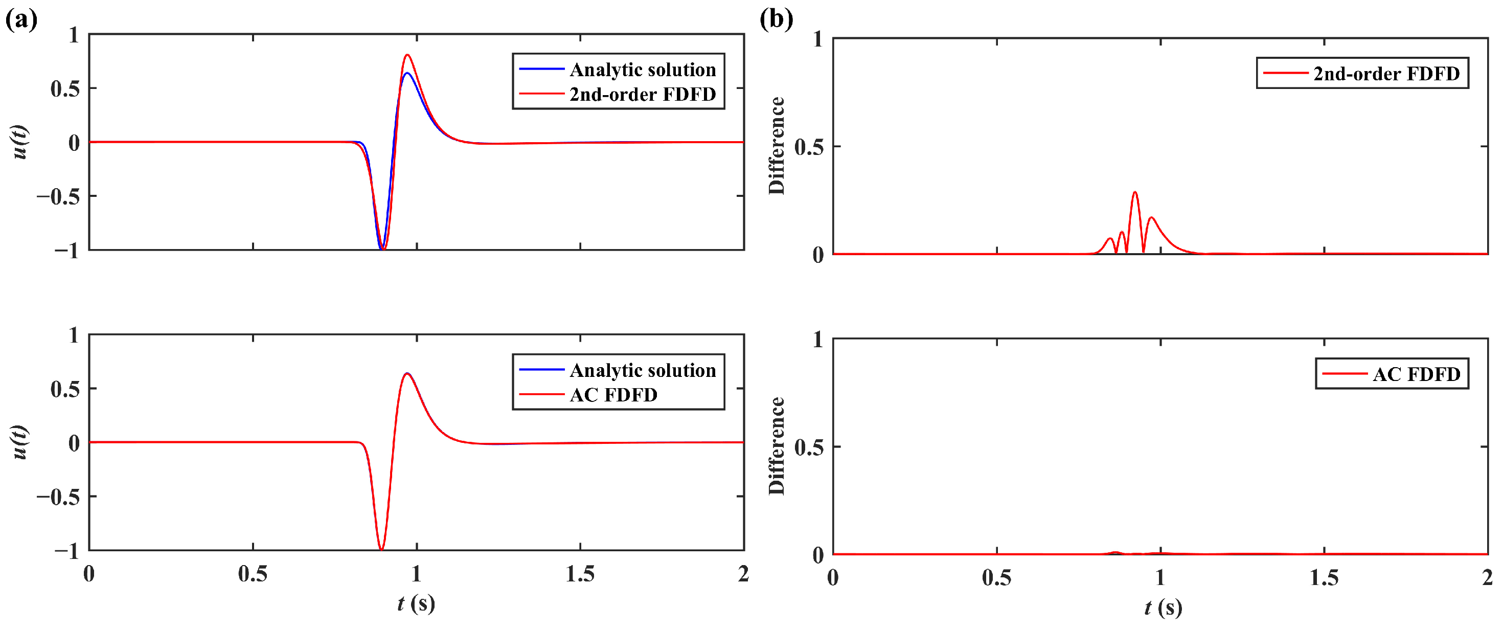
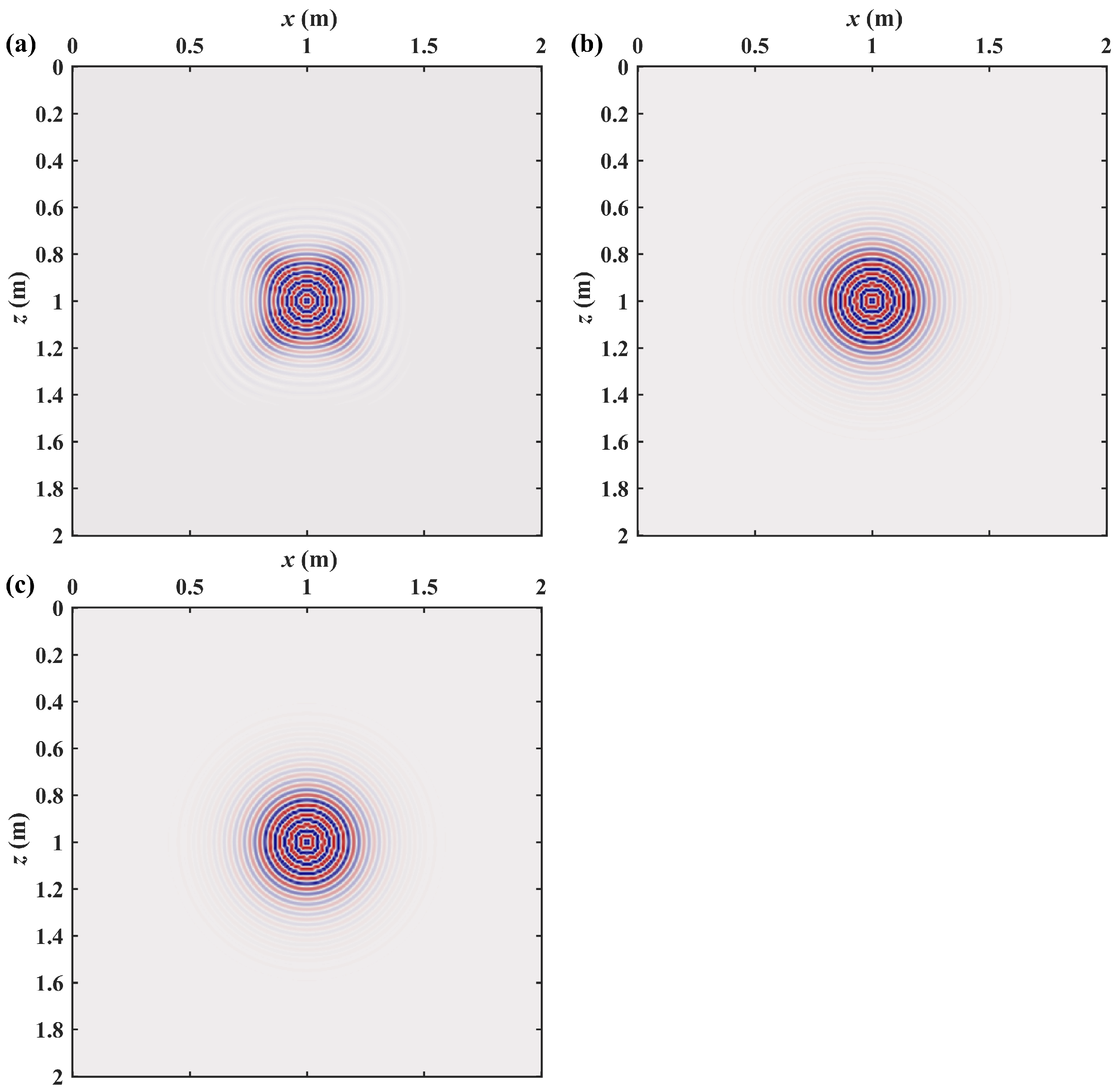
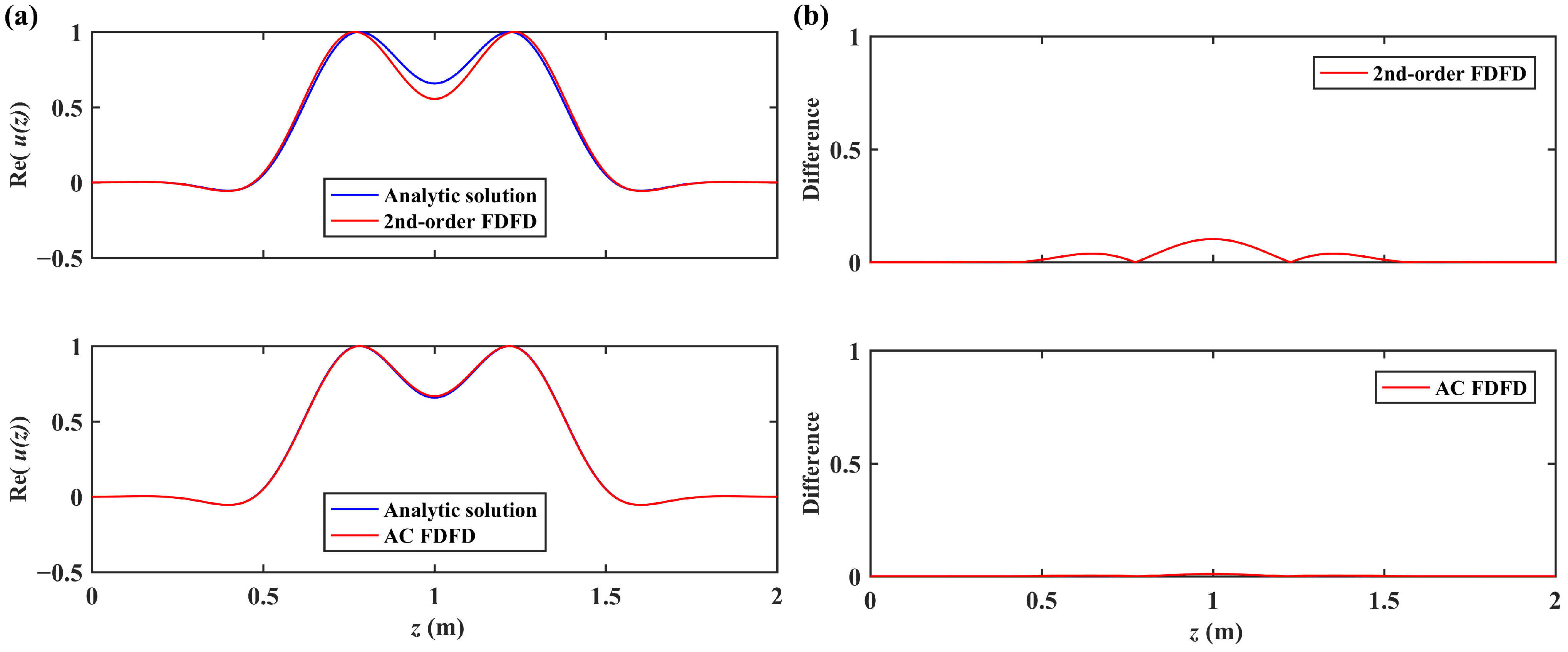
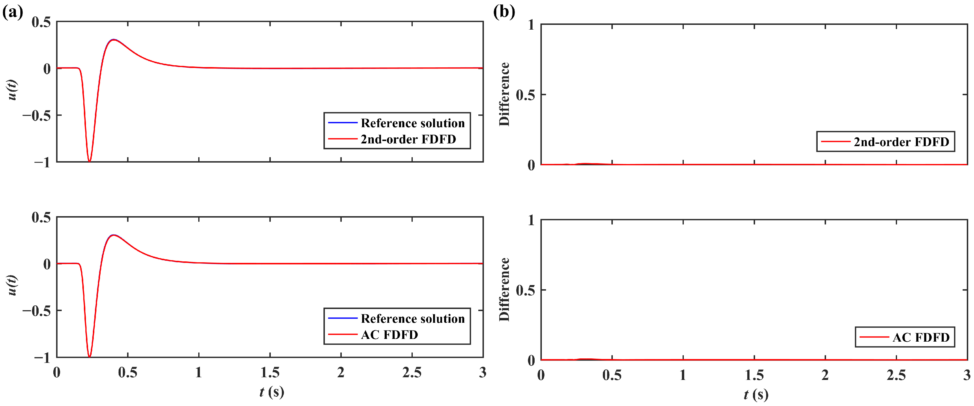
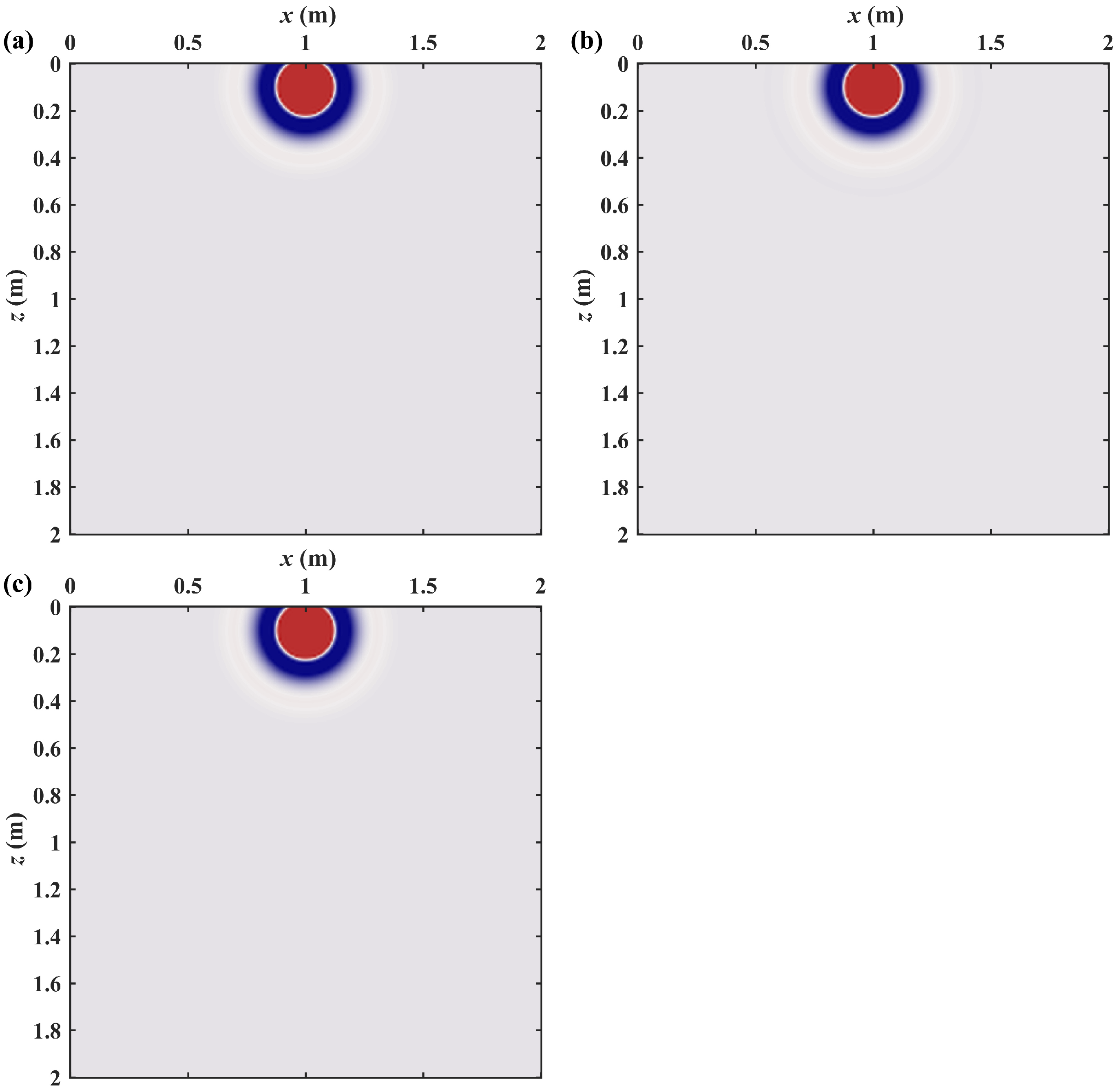
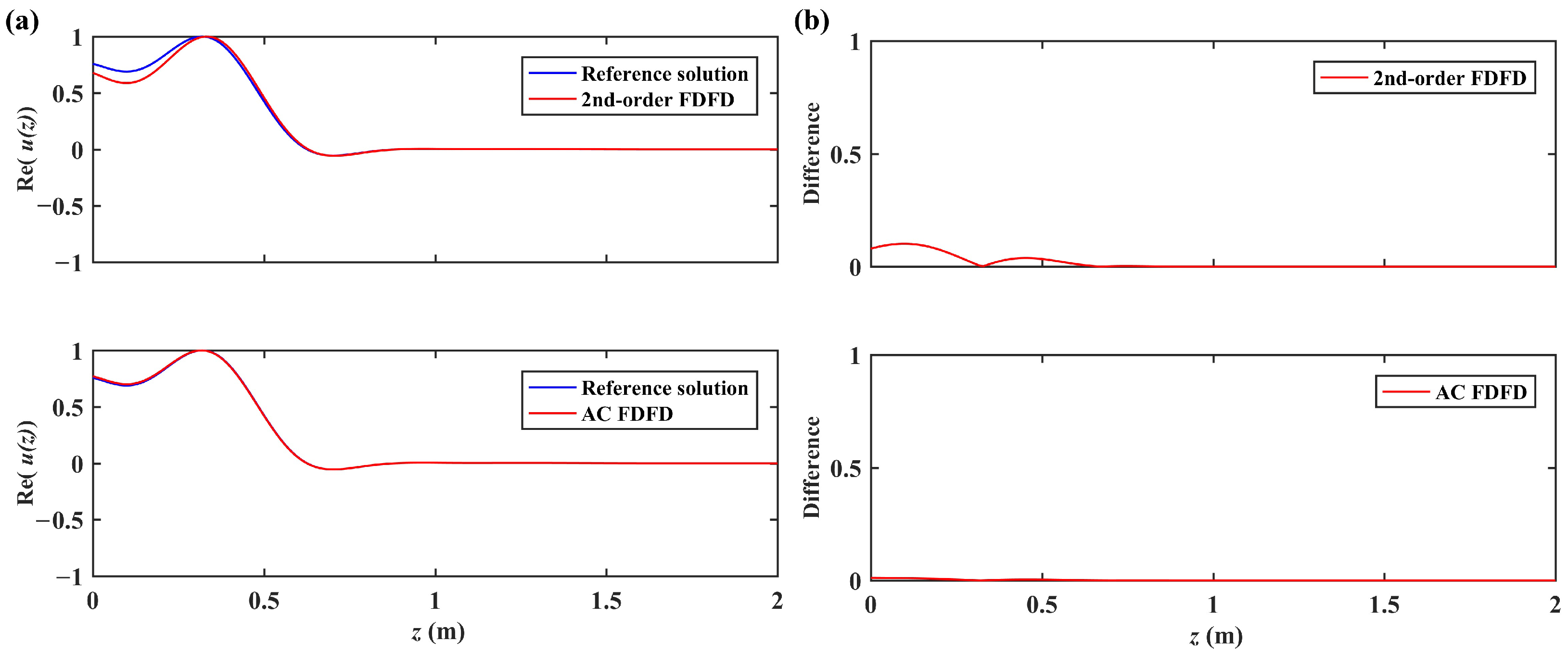
The first example is a homogeneous TFC model with a large time-fractional order α = 1.9 . The number of spatial grid points is 201 × 201 and the grid intervals are Δ x = Δ z = 0.01 m . The constant model parameters are taken as κ = 1 and μ = 1 . Twenty CFS PML layers are added to each side of the TFC model as an absorbing boundary condition. The source term is taken as a point source with Ricker time function of 1 2 π f d t t 0 2 e π f d t t 0 2 (see [39]), where f p denotes the dominant frequency (taken as 20 Hz in this work) and t 0 is the time delay (taken as 2.5 / f p in this work). The point source is located at the model center. The considered frequencies for numerical solution are sampled from 1 / 3 Hz to 60 Hz with an interval of 1 / 3 Hz . The frequency-domain numerical solution is also transformed to the time-domain numerical solution using an inverse fast Fourier transform. Figure 2 presents the comparisons between the transformed time-domain analytical solution and the corresponding numerical solutions obtained by the 2nd-order FDFD method and AC FDFD method at ( x , z ) = ( 1 m , 0 m ) . Figure 3 presents the comparisons of the real components of frequency–space domain solutions at 30 Hz obtained by the analytical solution and the above two FDFD methods. Figure 4 gives the further comparisons of the first vertical lines of the solutions in Figure 3. Figure 2, Figure 3 and Figure 4 show that the AC FDFD method can obtain a more accurate numerical solution than the second-order FDFD method for this homogeneous TFC case with α = 1.9 . Additionally, the computational times for the second-order FDFD method and AC FDFD method for this model are 1.3 s and 2.0 s , respectively. Therefore, the two-FDFD method costs a similar computational time to this model.
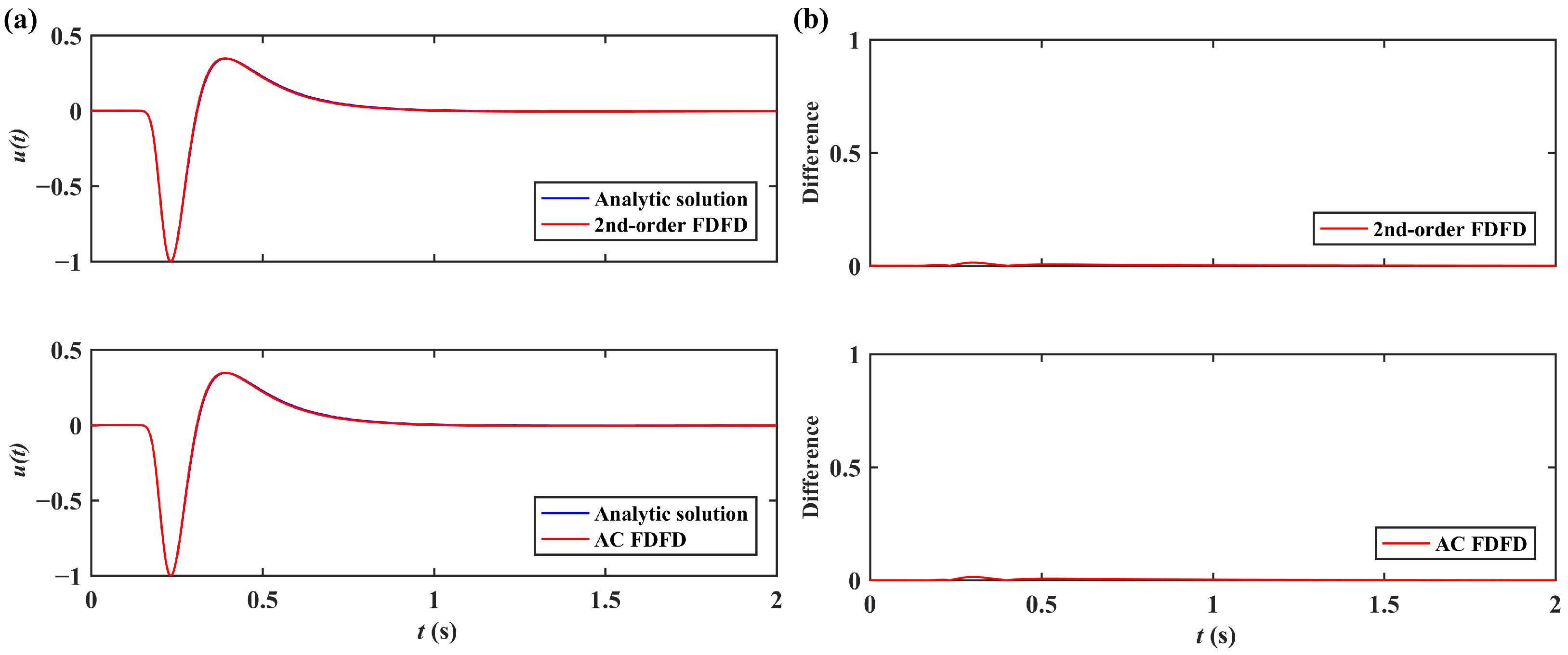
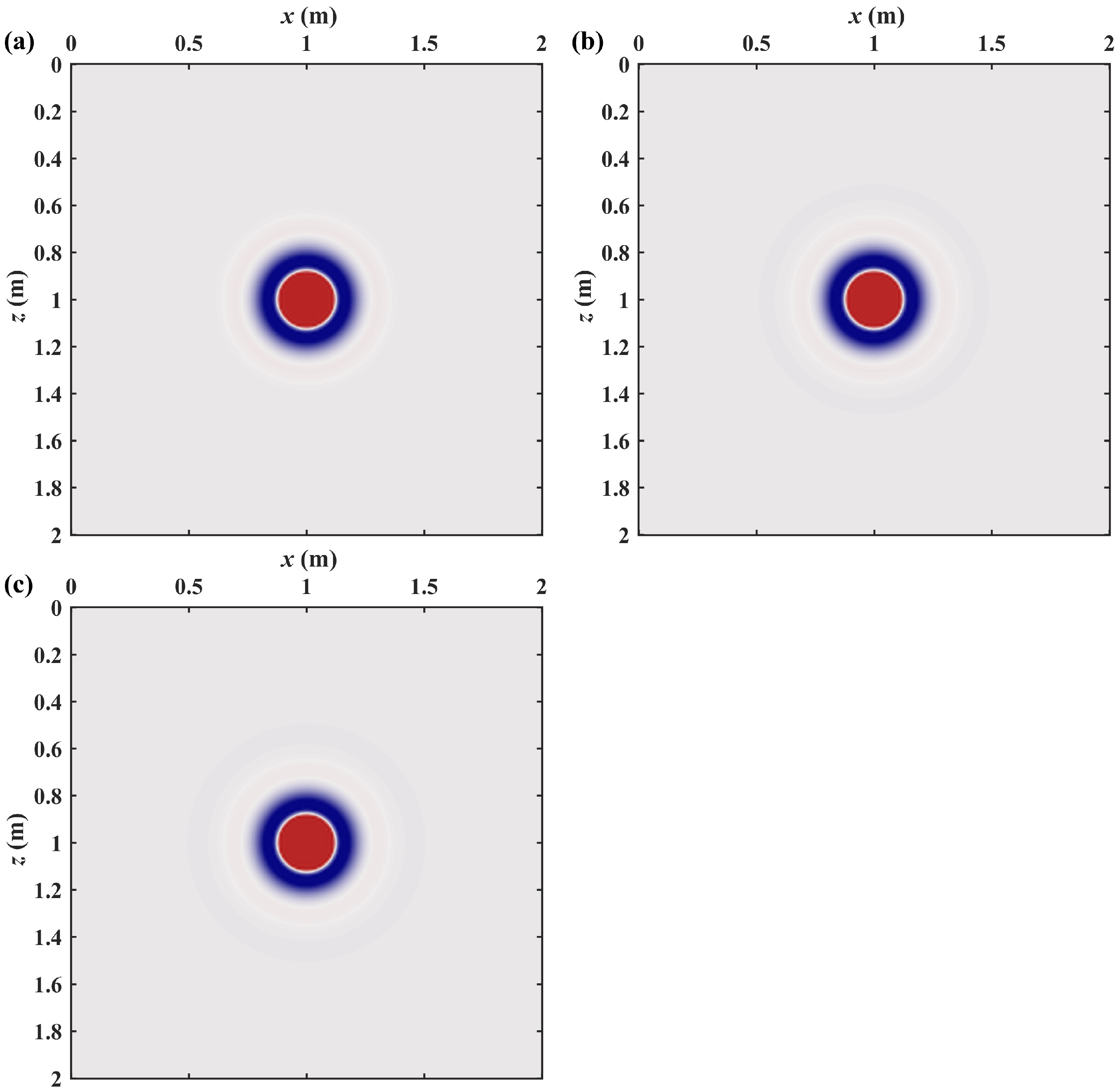
The second example considers almost the same TFC model as the first example except that the time-fractional order α is revised to 1.1. Figure 5 presents the comparisons between the transformed time-domain analytical solution and the corresponding numerical solutions obtained by second-order FDFD method and AC FDFD method at ( x , z ) = ( 1 m , 0 m ) . Figure 6 presents the comparisons of the real components of the frequency–space domain solutions at 50 Hz obtained by the analytical solution and the above two FDFD methods. Figure 7 gives the further comparisons of the first vertical lines of the solutions in Figure 6. Figure 5, Figure 6 and Figure 7 show that the AC FDFD method can obtain a little more accurate numerical solution than the second-order FDFD method for this homogeneous TFC case with α = 1.1 . Additionally, the computational times for the second-order FDFD method and AC FDFD method for this model are 1.3 s and 2.0 s , respectively. Therefore, the two FDFD methods cost a similar computational time for this model. In addition, the comparison between Figure 2 and Figure 5 shows that the second-order FDFD method can obtain a more accurate numerical solution for TFC model with smaller time-fractional order α .
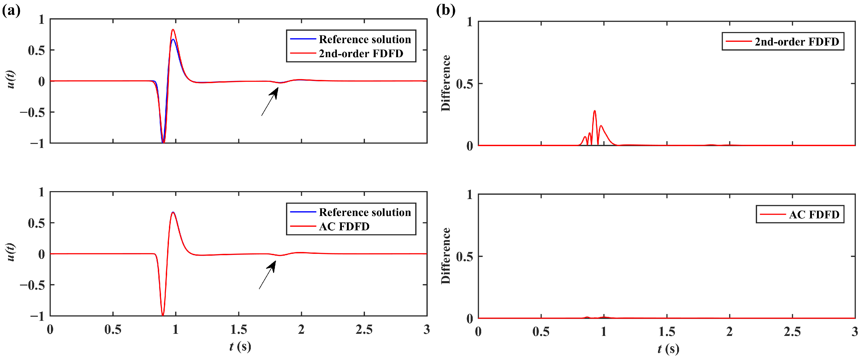
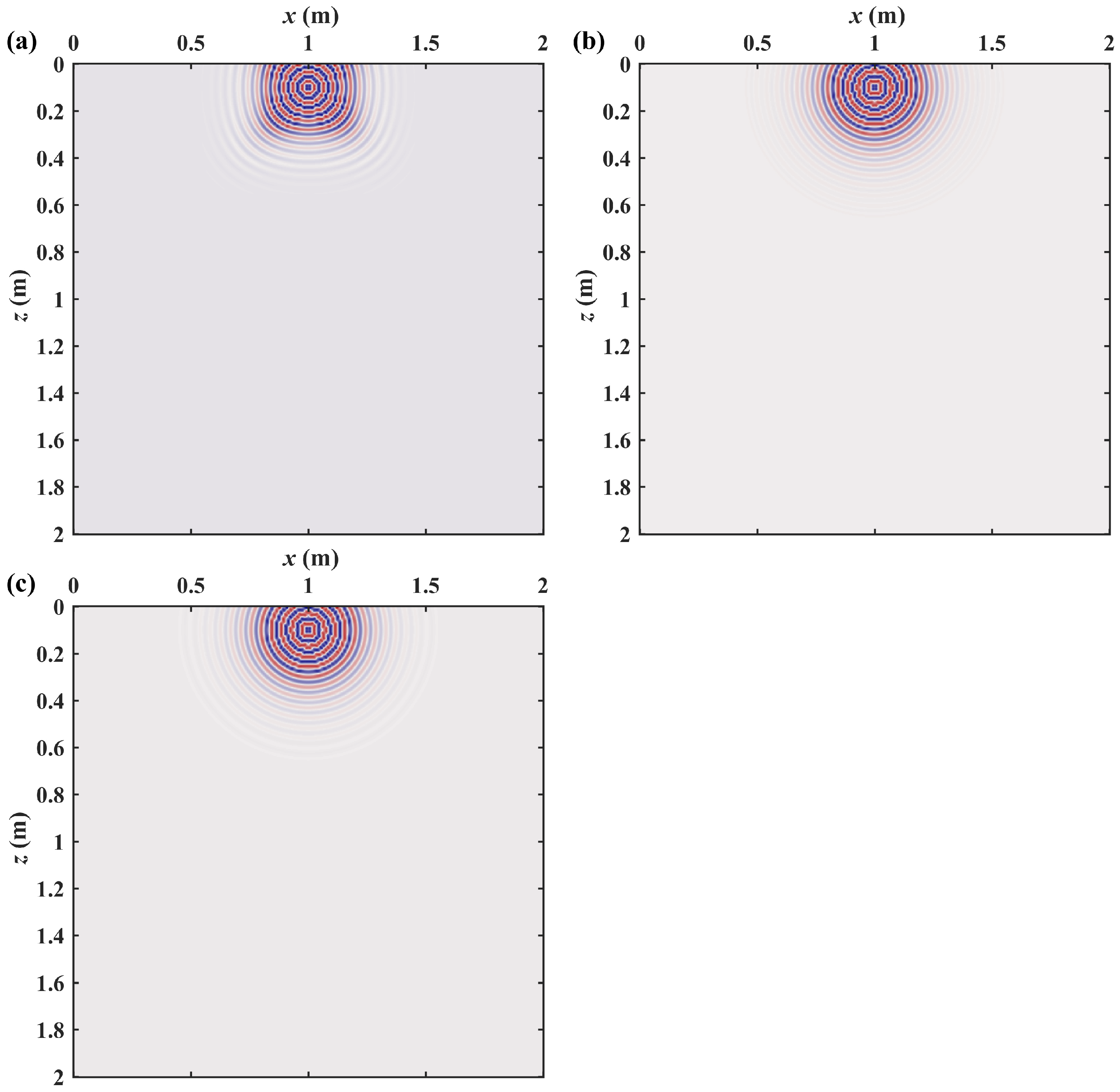
The third example also considers almost the same TFC model as the first example except the model parameter μ is revised to a two-layer model and the source location is revised to ( x , z ) = ( 1 m , 0.1 m ) . The top layer and the bottom layer of this model have the same thickness and take values of μ as 1 and 4, respectively. For validating the numerical solutions of this heterogeneous TFC equation, we apply the Taylor-expansion-based 72nd-order finite difference (see [40,41]) to approximate the spatial derivatives of the frequency-domain TFC equation and form a 72nd-order FDFD method as a reference solution, which can be highly accurate but computationally expensive due to the big bandwidth of the FDFD system matrix (see [32]). Figure 8 presents the comparisons between the transformed time-domain reference solution and the corresponding numerical solutions obtained by second-order FDFD method and AC FDFD method at ( x , z ) = ( 0 m , 0 m ) . Figure 9 presents the comparisons of the real components of frequency–space domain solutions at 30 Hz obtained by the reference solution and the above two FDFD methods. Figure 10 gives further comparisons of the first vertical lines of the solutions in Figure 9. Figure 8, Figure 9 and Figure 10 show that the AC FDFD method can obtain more an accurate numerical solution than the second-order FDFD method for this two-layer TFC model with α = 1.9 . In addition, the computational times for the second-order FDFD method, AC FDFD method, and the reference solution for this model are 1.4 s ,   2.0 s and 427 s , respectively. Therefore, the second-order FDFD method and AC FDFD method cost similar computational times for this model, and both are much more efficient than the reference solution. Additionally, Figure 8 and Figure 9 demonstrate that the TFC equation with the time-fractional order α = 1.9 shows strong attenuation that the reflection from the interface of two layers can be observed but very weak.
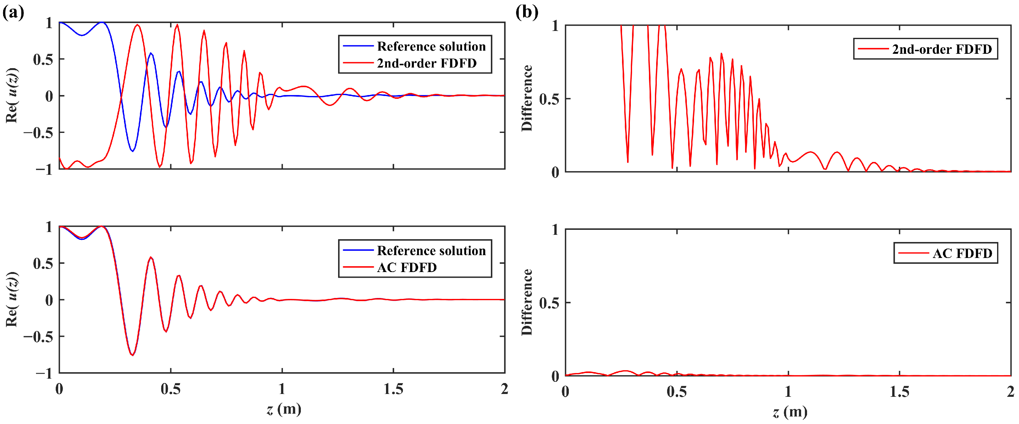
The fourth example considers almost the same TFC model as the third example except the time-fractional order α is revised to 1.1. Figure 11 presents the comparisons between the transformed time-domain reference solution and the corresponding numerical solutions obtained by the second-order FDFD method and AC FDFD method at ( x , z ) = ( 0 m , 0 m ) . Figure 12 presents the comparisons of the real components of the frequency–space domain solutions at 50 Hz obtained by the reference solution and the above two FDFD methods. Figure 13 gives the further comparisons of the first vertical lines of the solutions in Figure 12. Figure 11, Figure 12 and Figure 13 show that the AC FDFD method can obtain a little more accurate numerical solution than the second-order FDFD method for this two-layer TFC model with α = 1.1 . In addition, the computational times for the second-order FDFD method, AC FDFD method, and reference solution for this model are 1.3 s ,   2.0 s and 425 s , respectively. Therefore, the second-order FDFD method and AC FDFD method cost similar computational times for this model, and both are much more efficient than the reference solution. Additionally, Figure 11 and Figure 12 demonstrate that the TFC equation with the time-fractional order α = 1.1 shows a stronger attenuation than the TFC equation with α = 1.9 , and that the reflection from the interface of two layers cannot be observed in this case.

4. Conclusions

We develop a TFC equation with the CFS PML absorbing boundary condition in this work. Furthermore, we propose an efficient AC FDFD method for the numerical solution of TFC equation with the CFS PML absorbing boundary condition. Four numerical examples of typical TFC models show that the proposed AC FDFD method is more accurate than the 2nd-order FDFD method for the corresponding numerical solutions while requiring similar computational times. The key point of the AC FDFD method for solving the TFC equation is to minimize the error of substituting the corresponding plane-wave solution into the AC FDFD scheme. Such an idea can be generalized to other time-fractional equations.

Author Contributions

Methodology, W.X., J.B., J.C. and C.L.; validation, W.X., J.B., J.C. and C.L.; formal analysis, W.X., J.B., J.C. and C.L.; investigation, W.X., J.B., J.C. and C.L.; writing—original draft preparation, W.X., J.B., J.C. and C.L.; writing—review and editing, W.X., J.B., J.C. and C.L.; funding acquisition, W.X., J.B., J.C. and C.L. All authors have read and agreed to the published version of the manuscript.

Funding

This work is supported by the National Natural Science Foundation of China (grant no. 42374128, 42174161, and 12261058), China Postdoctoral Science Foundation (grant no. 2022M711004), and the Jiangsu Province Science Fund for Distinguished Young Scholars (grant no. BK20200021).

Data Availability Statement

The data of the numerical simulation used to support the findings of this study are included within the paper.

Conflicts of Interest

The authors declare no conflicts of interest.

References

  1. Compte, A.; Metzler, R. The generalized Cattaneo equation for the description of anomalous transport processes. J. Phys. A Math. Gen. 1997, 30, 7277. [Google Scholar] [CrossRef]
  2. Awad, E.; Metzler, R. Crossover dynamics from superdiffusion to subdiffusion: Models and solutions. Fract. Calc. Appl. Anal. 2020, 23, 55–102. [Google Scholar] [CrossRef]
  3. Nong, L.; Yi, Q.; Cao, J.; Chen, A. Fast Compact Difference Scheme for Solving the Two-Dimensional Time-Fractional Cattaneo Equation. Fractal Fract. 2022, 6, 438. [Google Scholar] [CrossRef]
  4. Povstenko, Y. Fractional Cattaneo-type equations and generalized thermoelasticity. J. Therm. Stress. 2011, 34, 97–114. [Google Scholar] [CrossRef]
  5. Qi, H.; Jiang, X. Solutions of the space-time fractional Cattaneo diffusion equation. Phys. A Stat. Mech. Its Appl. 2011, 390, 1876–1883. [Google Scholar] [CrossRef]
  6. Qi, H.T.; Xu, H.Y.; Guo, X.W. The Cattaneo-type time fractional heat conduction equation for laser heating. Comput. Math. Appl. 2013, 66, 824–831. [Google Scholar] [CrossRef]
  7. Ghazizadeh, H.; Maerefat, M.; Azimi, A. Explicit and implicit finite difference schemes for fractional Cattaneo equation. J. Comput. Phys. 2010, 229, 7042–7057. [Google Scholar] [CrossRef]
  8. Zhao, X.; Sun, Z.Z. Compact Crank–Nicolson schemes for a class of fractional Cattaneo equation in inhomogeneous medium. J. Sci. Comput. 2015, 62, 747–771. [Google Scholar] [CrossRef]
  9. Ren, J.; Gao, G.h. Efficient and stable numerical methods for the two-dimensional fractional Cattaneo equation. Numer. Algorithms 2015, 69, 795–818. [Google Scholar] [CrossRef]
  10. Wei, L. Analysis of a new finite difference/local discontinuous Galerkin method for the fractional Cattaneo equation. Numer. Algorithms 2018, 77, 675–690. [Google Scholar] [CrossRef]
  11. Li, H.; Jiang, W.; Li, W. Space-time spectral method for the Cattaneo equation with time fractional derivative. Appl. Math. Comput. 2019, 349, 325–336. [Google Scholar] [CrossRef]
  12. Chen, A.; Nong, L. Efficient Galerkin finite element methods for a time-fractional Cattaneo equation. Adv. Differ. Equ. 2020, 2020, 1–21. [Google Scholar] [CrossRef]
  13. Berenger, J.P. A perfectly matched layer for the absorption of electromagnetic waves. J. Comput. Phys. 1994, 114, 185–200. [Google Scholar] [CrossRef]
  14. Fu, L.Y.; Wu, R.S. Infinite boundary element absorbing boundary for wave propagation simulations. Geophysics 2000, 65, 596–602. [Google Scholar] [CrossRef]
  15. Xu, W.H.; Ba, J.; Carcione, J.M.; Yang, Z.F.; Yan, X.F. A simplified calculation for adaptive coefficients of finite-difference frequency-domain method. Appl. Geophys. 2023, 20, 1–16. [Google Scholar] [CrossRef]
  16. Zhang, L.X.; Fu, L.Y.; Pei, Z.L. Finite difference modeling of Biot’s poroelastic equations with unsplit convolutional PML and rotated staggered grid. Chin. J. Geophys. 2010, 53, 2470–2483. [Google Scholar]
  17. Fu, B.Y.; Fu, L.Y.; Wei, W.; Zhang, Y. Boundary-reflected waves and ultrasonic coda waves in rock physics experiments. Appl. Geophys. 2016, 13, 667–682. [Google Scholar] [CrossRef]
  18. Fu, L.Y.; Fu, B.Y.; Sun, W.; Han, T.; Liu, J. Elastic wave propagation and scattering in prestressed porous rocks. Sci. China Earth Sci. 2020, 63, 1309–1329. [Google Scholar] [CrossRef]
  19. Komatitsch, D.; Martin, R. An unsplit convolutional perfectly matched layer improved at grazing incidence for the seismic wave equation. Geophysics 2007, 72, SM155–SM167. [Google Scholar] [CrossRef]
  20. Martin, R.; Komatitsch, D. An unsplit convolutional perfectly matched layer technique improved at grazing incidence for the viscoelastic wave equation. Geophys. J. Int. 2009, 179, 333–344. [Google Scholar] [CrossRef]
  21. Saenger, E.H.; Gold, N.; Shapiro, S.A. Modeling the propagation of elastic waves using a modified finite-difference grid. Wave Motion 2000, 31, 77–92. [Google Scholar] [CrossRef]
  22. Fu, L.Y.; Zhang, Y.; Pei, Z.; Wei, W.; Zhang, L. Poroelastic finite-difference modeling for ultrasonic waves in digital porous cores. Earthq. Sci. 2014, 27, 285–299. [Google Scholar] [CrossRef]
  23. Zhang, Y.; Fu, L.Y.; Zhang, L.; Wei, W.; Guan, X. Finite difference modeling of ultrasonic propagation (coda waves) in digital porous cores with un-split convolutional PML and rotated staggered grid. J. Appl. Geophys. 2014, 104, 75–89. [Google Scholar] [CrossRef]
  24. Yang, H.; Fu, L.Y.; Fu, B.Y.; Du, Q. Poro-acoustoelasticity finite-difference simulation of elastic wave propagation in prestressed porous media. Geophysics 2022, 87, T329–T345. [Google Scholar] [CrossRef]
  25. Yang, H.; Fu, L.Y.; Li, H.; Du, Q.; Zheng, H. 3D acoustoelastic FD modeling of elastic wave propagation in prestressed solid media. J. Geophys. Eng. 2023, 20, 297–311. [Google Scholar] [CrossRef]
  26. Hou, W.; Fu, L.Y.; Carcione, J.M.; Wang, Z.; Wei, J. Simulation of thermoelastic waves based on the Lord-Shulman theory. Geophysics 2021, 86, T155–T164. [Google Scholar] [CrossRef]
  27. Liu, Y.; Fu, L.Y.; Deng, W.; Hou, W.; Carcione, J.M.; Wei, J. Simulation of wave propagation in thermoporoelastic media with dual-phase-lag heat conduction. J. Therm. Stress. 2023, 46, 1–19. [Google Scholar] [CrossRef]
  28. Bekri, Z.; ERTÜRK, V.S.; Kumar, P.; Govindaraj, V. Some novel analysis of two different Caputo-type fractional-order boundary value problems. Results Nonlinear Anal. 2022, 5, 299–311. [Google Scholar] [CrossRef]
  29. Prieur, F.; Holm, S. Nonlinear acoustic wave equations with fractional loss operators. J. Acoust. Soc. Am. 2011, 130, 1125–1132. [Google Scholar] [CrossRef]
  30. Pei, Z.; Fu, L.Y.; Sun, W.; Jiang, T.; Zhou, B. Anisotropic finite-difference algorithm for modeling elastic wave propagation in fractured coalbeds. Geophysics 2012, 77, C13–C26. [Google Scholar] [CrossRef]
  31. Chen, L.; Huang, J.; Fu, L.Y.; Peng, W.; Song, C.; Han, J. A Compact High-Order Finite-Difference Method with Optimized Coefficients for 2D Acoustic Wave Equation. Remote Sens. 2023, 15, 604. [Google Scholar] [CrossRef]
  32. Xu, W.; Zhong, Y.; Wu, B.; Gao, J.; Liu, Q.H. Adaptive complex frequency with V-cycle GMRES for preconditioning 3D Helmholtz equation. Geophysics 2021, 86, T349–T359. [Google Scholar] [CrossRef]
  33. Xu, W.; Wu, B.; Zhong, Y.; Gao, J.; Liu, Q.H. Adaptive 27-point finite-difference frequency-domain method for wave simulation of 3D acoustic wave equation. Geophysics 2021, 86, T439–T449. [Google Scholar] [CrossRef]
  34. Jo, C.H.; Shin, C.; Suh, J.H. An optimal 9-point, finite-difference, frequency-space, 2-D scalar wave extrapolator. Geophysics 1996, 61, 529–537. [Google Scholar] [CrossRef]
  35. Zhao, H.; Wang, S.; Xu, W.; Gao, J. Complex-valued adaptive-coefficient finite difference frequency domain method for wavefield modeling based on diffusive-viscous wave equation. Geophysics 2023, 89, 1–75. [Google Scholar] [CrossRef]
  36. Golub, G.H.; Van Loan, C.F. Matrix Computations; JHU Press: Baltimore, MD, USA, 2013. [Google Scholar]
  37. Carcione, J.M.; Kosloff, D.; Kosloff, R. Wave propagation simulation in a linear viscoacoustic medium. Geophys. J. Int. 1988, 93, 393–401. [Google Scholar] [CrossRef]
  38. Petra, C.G.; Schenk, O.; Anitescu, M. Real-time stochastic optimization of complex energy systems on high-performance computers. Comput. Sci. Eng. 2014, 16, 32–42. [Google Scholar] [CrossRef]
  39. Ricker, N. Further developments in the wavelet theory of seismogram structure. Bull. Seismol. Soc. Am. 1943, 33, 197–228. [Google Scholar] [CrossRef]
  40. Dablain, M. The application of high-order differencing to the scalar wave equation. Geophysics 1986, 51, 54–66. [Google Scholar] [CrossRef]
  41. Liu, Y. Finite-difference numerical modeling of any even order accuracy. Oil Geophys. Prospect. 1998, 33, 1–10. [Google Scholar]
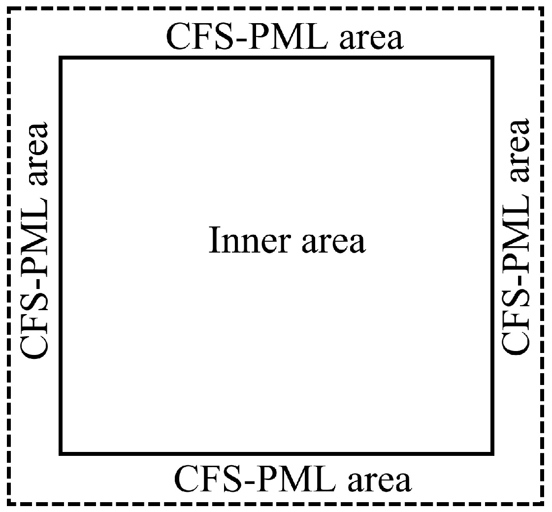
Figure 1. The schematic of the computational area for the TFC equation with CFS PML.
Fractalfract 08 00146 g001
Figure 2. (a) The amplitude comparison and (b) the differences between the transformed time-domain analytical solution and the corresponding numerical solutions obtained by 2nd-order FDFD method and AC FDFD method at (x, z) = (1 m, 0 m) for homogeneous TFC model with α = 1.9 .
Fractalfract 08 00146 g002
Figure 3. The comparisons of the real components of frequency–space domain solutions at 30 Hz obtained by (a) 2nd-order FDFD method, (b) AC FDFD method, and (c) analytical solution for homogeneous TFC model with α = 1.9 .
Fractalfract 08 00146 g003
Figure 4. (a) The amplitude comparison and (b) the differences between the frequency–space domain analytical solution and the corresponding numerical solutions obtained by 2nd-order FDFD method and AC FDFD method at 30 Hz and x = 0 m for the homogeneous TFC model with α = 1.9 .
Fractalfract 08 00146 g004
Figure 5. (a) The amplitude comparison and (b) the differences between the transformed time-domain analytical solution and the corresponding numerical solutions obtained by 2nd-order FDFD method and AC FDFD method at (x, z) = (1 m, 0 m) for homogeneous TFC model with α = 1.1 .
Fractalfract 08 00146 g005
Figure 6. The comparisons of the real components of frequency–space domain solutions at 50 Hz obtained by (a) 2nd-order FDFD method, (b) AC FDFD method and (c) analytical solution for homogeneous TFC model with α = 1.1 .
Fractalfract 08 00146 g006
Figure 7. (a) The amplitude comparison and (b) the differences between the frequency–space domain analytical solution and the corresponding numerical solutions obtained by 2nd-order FDFD method and AC FDFD method at 50 Hz and x = 0 m for homogeneous TFC model with α = 1.1 .
Fractalfract 08 00146 g007
Figure 8. (a) The amplitude comparison and (b) the differences between the transformed time-domain reference solution and the corresponding numerical solutions obtained by 2nd-order FDFD method and AC FDFD method at ( x , z ) = ( 0 m , 0 m ) for two-layer TFC model with α = 1.9 . The black arrows point to the reflection from the interface between two layers.
Fractalfract 08 00146 g008
Figure 9. The comparisons of the real components of frequency–space domain solutions at 30 Hz obtained by (a) 2nd-order FDFD method, (b) AC FDFD method and (c) reference solution for two-layer TFC model with α = 1.9 .
Fractalfract 08 00146 g009
Figure 10. (a) The amplitude comparison and (b) the differences between the frequency–space domain reference solution and the corresponding numerical solutions obtained by 2nd-order FDFD method and AC FDFD method at 30 Hz and x = 0 m for two-layer TFC model with α = 1.9 .
Fractalfract 08 00146 g010
Figure 11. (a) The amplitude comparison and (b) the differences between the transformed time-domain reference solution and the corresponding numerical solutions obtained by 2nd-order FDFD method and AC FDFD method at ( x , z ) = ( 0 m , 0 m ) for two-layer TFC model with α = 1.1 .
Fractalfract 08 00146 g011
Figure 12. The comparisons of the real components of frequency–space domain solutions at 50 Hz obtained by (a) 2nd-order FDFD method, (b) AC FDFD method and (c) reference solution for homogeneous TFC model with α = 1.1 .
Fractalfract 08 00146 g012
Figure 13. (a) The amplitude comparison and (b) the differences between the frequency–space domain reference solution and the corresponding numerical solutions obtained by 2nd-order FDFD method and AC FDFD method at 50 Hz and x = 0 m for two-layer TFC model with α = 1.1 .
Fractalfract 08 00146 g013
Disclaimer/Publisher’s Note: The statements, opinions and data contained in all publications are solely those of the individual author(s) and contributor(s) and not of MDPI and/or the editor(s). MDPI and/or the editor(s) disclaim responsibility for any injury to people or property resulting from any ideas, methods, instructions or products referred to in the content.