Article

Event-Triggered Fuzzy Adaptive Predefined-Time Control for Fractional-Order Nonlinear Systems with Time-Varying Deferred Constraints and Its Application

1
School of Information Engineering, Henan University of Science and Technology, Luoyang 467023, China
2
Escuela de Ingenierías Industriales, Universidad de Extremadura, 06006 Badajoz, Spain
*
Authors to whom correspondence should be addressed.
Fractal Fract. 2024, 8(10), 613; https://doi.org/10.3390/fractalfract8100613
Submission received: 1 September 2024 / Revised: 3 October 2024 / Accepted: 17 October 2024 / Published: 20 October 2024
(This article belongs to the Section Engineering)

Abstract

:
This paper focuses on the fuzzy adaptive predefined-time control for fractional-order nonlinear systems with time-varying deferred constraints. First, a modified dynamic surface control technique is introduced to address the problem of computational complexity exposed in the backstepping framework, and the interval type-2 fuzzy logic systems are applied to model the unknown nonlinearities of the systems. Next, a shifting function and the barrier Lyapunov function with variational barrier bounds are formulated to deal with the constraints issue. Particularly, the constraint conditions can be satisfied within a predetermined time, even if they are transgressed initially. Furthermore, a switching threshold event-triggered controller is devised to balance the control energy and communication resources. With the help of the predefined-time stability criterion, it is proven that the presented predefined-time event-triggered controller can ensure that all the signals involved in the closed-loop system are bounded and the tracking error fluctuates to a small neighborhood of the origin in a predefined-time interval. Finally, two simulation examples are provided to confirm the effectiveness of the put-forward control algorithm.

1. Introduction

Due to its unique memory and heredity characteristics, the dynamic performance of many natural phenomena can be more precisely described by fractional-order (FO) systems, such as economic growth, viscoelastic systems, and robotics systems [1]. Therefore, the control problem of fractional-order nonlinear systems (FONSs) has gained extensive attention from scholars, and many control approaches have been proposed in the past few decades, for instance, adaptive backstepping design [2,3], robust control [4], sliding mode control [5] and so on. In particular, adaptive backstepping control is one of the most universally used methods to deal with FONSs [6], in which some intermediate variables are recursively used as pseudo-control signals in the design process. However, the backstepping design procedure will face the sticky computational complexity caused by the repeated derivations of virtual control signals. In response, the dynamic surface control (DSC) technology [7] was proposed to handle the above issue by introducing a nonlinear filter. Thereafter, ref. [8] further extended to study an adaptive fuzzy decentralized DSC scheme for FO nonlinear large-scale systems. However, the reality is that practical systems often involve mostly unknown nonlinear functions due to modeling inaccuracies, external disturbances, and other factors. It is well known that fuzzy logic systems (FLSs) are universal intelligent approximators to identify unknown nonlinear functions. For instance, Song et al. [9] proposed an observer-based adaptive fuzzy resilient control scheme for FONSs with time-varying delays. Meanwhile, ref. [10] reported an adaptive fuzzy decentralized control method for FONSs in which the unknown nonlinear functions were modeled using type-1 FLSs. However, it is proven that type-1 FLSs have trouble modeling and minimizing the effect of uncertainties [11]. That is mainly because a type-1 fuzzy set is certain in the situation that it has a clear membership grade for each particular input. To address the above issues, type-2 fuzzy sets were thus established [12], where each input for such fuzzy sets has a unity secondary membership grade determined by the upper and lower type-1 membership functions. Recently, ref. [13] investigated an adaptive interval type-2 fuzzy sliding mode controller design problem. In [14], the authors proposed an adaptive type-2 fuzzy backstepping control for FONSs with unknown dead zones. Nonetheless, it is unavoidable that the time-triggered-based strategy will need to update the control signals frequently in the aforementioned control algorithms, which will result in redundant resource waste.
To reduce the communication burden, the event-triggered control (ETC) is introduced owing to its advantage in reducing update frequency. Therefore, numerous control tactics involved in different event-triggered mechanisms (ETMs) have been proposed [15,16,17,18,19]. The event-triggered tracking control tactic for FONSs with external disturbances was studied in [15]. In [16], the authors proposed an event-triggered output feedback control scheme for FONSs. Frankly speaking, these ETMs adopted in [15,16] are static. Correspondingly, a dynamic event-triggered mechanism was proposed in [17] to improve the flexibility of parameter design. However, it may cause controller impulses when the controller’s magnitude is large to some extent. To this end, an improved event-triggered mechanism with a decreasing function was developed in [18] for FO multi-agent systems to efficiently prevent excessive control energies. Nevertheless, the shortcoming of this decreasing threshold event-triggered mechanism is that it cannot provide the same level of control precision as dynamic and relative threshold mechanisms when the controller amplitude is small. Hence, it is necessary to design a more effective event-triggered strategy for achieving a balance between different ETMs. In addition, it is usually desired that the system states can converge to the stable stages rapidly within an expected time rather than asymptotically in practice.
To meet the need for specific convergence properties, the concepts of finite-time and fixed-time stability were introduced. To mention a few, ref. [20] proposed a finite-time adaptive neural resilient DSC method for FO systems. Ref. [21] provided an adaptive fixed-time tracking control method for multi-agent systems. However, it is worth noting that the convergence time of finite-time control heavily depends on the initial values of the controlled systems, and the convergence time of fixed-time control is determined by numerous defined scales. In this case, the predefined time control concept was proposed to avoid the aforementioned problems, which can directly set the convergence time by one design parameter. To this end, ref. [22] presented an adaptive fuzzy predefined-time dynamic surface control method for attitude tracking of spacecraft with state constraints. In [19], an event-triggered predefined-time output feedback control problem was studied for FONSs. Furthermore, it is important to consider how to ensure that the control process in practical systems maintains a fast response speed and achieves high control accuracy.
In fact, fruitful research results about the constraint problems have been gained over the past few decades, including state constraints [23], input constraints [24] and output constraints [25]. However, the above research results only involve static constraints, while the dynamic constraints that vary with the target trajectory are requested in practice. In [26], the authors applied an asymmetric time-varying barrier Lyapunov function (BLF) to ensure constraint satisfaction. In [27], the fixed-time adaptive fuzzy control scheme was proposed for the nonlinear systems via the time-varying BLF technique. However, the methods proposed in [26,27] are based on the additional assumptions that certain information on the initial tracking condition is available or the constraints are imposed from the beginning of system operation and are satisfied initially. To overcome the drawbacks, a novel BLF with variational barrier bounds was first introduced to study the tracking control method capable of asymmetric yet time-varying full state constraints under completely unknown initial conditions in [28]. Subsequently, ref. [29] proposed an event-triggered fuzzy adaptive control scheme against time-varying output constraints. However, the results of [26,27,28,29] are only proposed for integer-order systems and are not directly applicable to FONSs. Although an adaptive fuzzy decentralized control scheme for FONS with time-varying deferred constraints was developed in [30], there are still some issues that need to be solved for the recursive control design of FONSs with time-varying deferred constraints.
Motivated by the above results, an event-triggered fuzzy adaptive predefined-time control is studied for FONSs with time-varying deferred constraints and external disturbances in this article. The main contribution points are summarized as follows:
( 1 ) Compared With the prior constrained works [25,26,27], the paper tactfully considers a more universal situation that the initial state of the FONSs is completely unknown by utilizing an error-shifting transformation function and the BLF with variational barrier bounds, where the constraint conditions will still be adhered to after a predetermined settling time, even if they are transgressed initially. Besides, compared with the finite-time control method [20], the predefined-time control is introduced because it can directly set the convergence time only by a design parameter.
( 2 ) In contrast to the existing literature [19,21], the modified DSC technique including the hyperbolic tangent function is applied to overcome the sticky computational complexity problem caused by the repeated derivations of virtual control signals while avoiding the potential singularity problem. Particularly, the auxiliary term Λ ^ 1 2 ϑ 1 Λ ^ 1 2 ϑ 1 2 + ϖ 2 is constructed to compensate for the boundary layer errors as opposed to the sign functions that cause the chattering phenomenon [31], while the term is a smooth function due to its differentiability, and thus can effectively replace the sign functions.
( 3 ) Unlike the conventional ETC in [15,16,19], a switching threshold event-triggered technique with a decreasing and dynamic threshold function is developed to trade off the control energy and communication resources. Meanwhile, different from the switching ETC scheme with a fixed threshold and relative threshold event-triggered mechanism in [32], the proposed event-triggered mechanism increases the system flexibility by setting a dynamic parameter.
The remaining contents of this article consist of the following sections. Section 2 gives the preliminaries and formulates the investigated issue. An event-triggered adaptive interval type-2 fuzzy control approach is proposed for FONSs with time-varying deferred constraints in Section 3. Section 4 provides two examples including a numerical example and an application example to demonstrate the effectiveness of the obtained theoretical results. Eventually, the whole work is summarized in Section 5.

2. System Description and Preliminaries

2.1. System Description

Consider the FONSs with the following form:
D t q x j ( t ) = g j ( x ¯ j ) x j + 1 ( t ) + f j ( x ¯ j ) + d j ( t ) , j = 1 , , n 1 , D t q x n ( t ) = g n ( x ¯ n ) u ( t ) + f n ( x ¯ n ) + d n ( t ) , y ( t ) = x 1 ( t ) ,
where q ( 0 , 1 ) is the system order, x ¯ j ( t ) = [ x 1 ( t ) , , x j ( t ) ] T R j , j = 1 , , n are state vectors, y ( t ) R is the system output, u ( t ) R denotes the actual control input, and f j ( · ) and g j ( · ) are unknown and known smooth nonlinear functions, respectively. d j ( t ) represents the unknown but bounded external disturbances satisfying | d j ( t ) | d j with d j being a positive constant.

2.2. Preliminaries

To obtain the desired result, some necessary definitions and lemmas are given in the following. For simplicity, the variable t will be omitted in some functions when the context is sufficiently explicit.
Definition 1 
([33]). The qth integral of continuous function f ( t ) is defined as
I t q f ( t ) = 1 Γ ( q ) 0 t f ( τ ) ( t τ ) 1 q d τ ,
and the qth Caputo fractional derivative with respect to time t is written as
D t q f ( t ) = 1 Γ ( 1 q ) 0 t f ( τ ) ( t τ ) q d τ ,
where 0 < q < 1 , Γ ( q ) = 0 + t q 1 e t d t represents the Gamma function with Γ ( 1 ) = 1 .
Lemma 1 
([30,34]). Suppose that a binary function V ( x ( t ) , a ( t ) ) is convex over Ω 1 × Ω 2 , and then, the qth time derivative of V ( x ( t ) , a ( t ) ) is calculated as:
D t q V ( x ( t ) , a ( t ) ) V x T D t q x ( t ) + V a T D t q a ( t ) .

2.3. Predefined-Time Stability Theory

Consider the following FONSs as
D t q 0 C x ¯ ( t ) = f ¯ 1 ( x ¯ , t ) , x ¯ ( 0 ) = x ¯ 0 ,
where x ¯ is the state of (5), f ¯ 1 ( x ¯ , t ) is a nonlinear smooth function, and the origin is assumed to be an equilibrium point of system (5).
Definition 2 
([35]). For a predefined-time T d , the origin of system (5) is said to be semi-global and practically predefined-time stable (SGPPTS). If there is a positive constant ε ¯ 0 , the solution x ¯ ( t ) ( x ¯ ( 0 ) = x ¯ 0 R n ) of the system (5) satisfies x ¯ ( x ¯ 0 , t ) ε ¯ 0 for any t T d .
Lemma 2 
([35,36]). If there exists a positive definite function V : R n R such that V ( x ¯ ) = 0 x ¯ = 0 and the solution x ¯ ( x ¯ 0 , t ) of system (5) satisfies
D t q 0 C V χ σ T d   V 1 + σ 2 χ σ T d   V 1 σ 2 + ρ ,
where 0 < σ < 1 , T d > 0 and ρ > 0 are constants. χ is a design parameter related to σ. Then, the origin of system (5) is SGPPTS within a predefined-time ( 2 T d ) 1 q .

2.4. Time-Varying Deferred Constraints

In practical engineering, the system outputs or states are typically needed to adhere to specific predefined restrictions due to the constraints of the physical environment and performance considerations. Thus, it is supposed that the output y ( t ) is constrained by time-varying barrier y ̲ ( t ) , namely,
y ( t ) ( y ̲ ( t ) , y ̲ ( t ) ) , t T f ,
where T f > 0 and y ̲ ( t ) is a positive function that can be set arbitrarily. Besides, this constraint is known as the deferred constraint because the system output is free of the constraint in the time period [ 0 , T f ) but must comply with the constraint within t T f .

2.5. Interval Type-2 Fuzzy Logic Systems

The unknown nonlinearities F ( z ¯ ) can be identified by interval type-2 fuzzy logic systems (IT2FLSs) in this work. Suppose that the IT2 fuzzy rule is constructed by the following IF-THEN fuzzy rules [37]: R m : IF x ¯ 1 is H ˜ 1 m and … and x ¯ n is H ˜ n m THEN y is Y ˜ m , where x ¯ 1 , , x ¯ n and y represent the antecedent scales and consequent scales of rule m, respectively; H ˜ i m denotes the IT2 fuzzy set, and H ˜ i m = [ y l m , y r m ] with i = 1 , , n , 1 m M , where M indicates the number of fuzzy rules; y l m and y r m represent crisp consequences. H ˜ i m involving the lower and upper membership functions ̲ H ˜ i m and ¯ H ˜ i m are characterized as
̲ H ¯ i m = τ ̲ i m exp 1 2 x ¯ i a i m z ̲ i m 2 , ¯ H ¯ i m = τ ¯ i m exp 1 2 x ¯ i a i m z ¯ i m 2 ,
where τ ̲ i m , τ ¯ i m , z ̲ i m , z ¯ i m and a i m denote defined scales with 0 < τ ̲ i m τ ¯ i m < 1 and z ̲ i m < z ¯ i m .
The total fired interval L m of the mth rule R m is L m ( x ¯ i ) = [ U ̲ m ( x ¯ i ) , U ¯ m ( x ¯ i ) ] , where U ̲ m ( x ¯ i ) = i = 1 n ̲ H ˜ i m and U ¯ m ( x ¯ i ) = i = 1 n ¯ H ˜ i m . By employing the average values of U ̲ l and U ¯ l , the output of the IT2FLSs can be expressed as
y = 1 2 i = 1 M ( U ̲ i y l i + U ¯ i y r i ) = W l T W r T φ l 2 φ r 2 = W T φ ,
where W l = [ y l 1 , , y l M ] T , W r = [ y r 1 , , y r M ] T , φ l = [ U ̲ l , , U ̲ M ] T , and φ r = [ U ¯ l , , U ¯ M ] T .
Lemma 3 
([37]). The unknown items F ( x ¯ i ) on the compact set Ω can be modeled by IT2FLSs:
sup x ¯ i Ω F ( x ¯ i ) W T φ ( x ¯ i ) ε ( x ¯ i ) ,
where W is the optimal weight vector and ε ( x ¯ i ) represents the approximation error satisfying | | ε ( x ¯ i ) | | ε ¯ with a positive constant ε ¯ .
Lemma 4 
([38]). For x R , there exists the inequality | x | x 2 x 2 + o 2 + o , where o = a exp ( b t ) > 0 with a is small constant.
Assumption 1. 
The desired signal y d ( t ) and its nth FO derivative are bounded and smooth, and suppose that there exists a positive function y ̲ d ( t ) such that y ̲ d ( t ) < y d ( t ) < y ̲ d ( t ) .
This paper aims to present an adaptive predefined-time control issue for FONSs (1), which can ensure that the constraint conditions are satisfied within a predetermined time, even if they are transgressed initially. Besides, all the signals involved in the closed-loop system (CLS) are bounded, and the tracking error can converge to a small neighborhood of the origin within a predefined time interval.

3. Main Results

In this section, by combining the backstepping method with the DSC technique, a fuzzy adaptive predefined-time control will be developed for (1), and the detailed design process and stability analysis will be shown in the following.

3.1. Controller Design

The coordinate transformations are defined as:
z 1 = y y d , z j = x j α ¯ j 1 , ϑ j 1 = α ¯ j 1 α j 1 ,
where z 1 and z j ( j = 2 , , n ) are the tracking error and the error surface, respectively. y d denotes reference signal, ϑ j 1 is the boundary layer error, and α ¯ j 1 is the filter output signal produced by the virtual control signal α j 1 through the modified FO filter.
To address the time-varying deferred constraints [28], a shifting function with 0 < T c T f is constructed as
η ( t ) = 1 T c t T c 2 , t [ 0 , T c ) , 1 , t [ T c , + ) ,
Remark 1. 
The shifting function η ( t ) (12) has the following intrinsic characteristics:
(1) It is strictly increasing for t [ 0 , T c ) with η ( t ) [ 0 , 1 ] for t 0 and η ( 0 ) = 0 ;
(2) It reaches the maximum value 1 at t = T c and remains unchanged for all t ( T c , ) ;
(3) D t q η ( t ) is bounded for t 0 .
Define ξ = η z 1 ; one can obtain
ξ = η z 1 , t [ 0 , T c ) , z 1 , t [ T c , + ) .
Remark 2. 
By multiplying the shifting function η, the surface error z 1 with a bounded and possible unknown initial value can be converted to a new variable ξ with zero initial conditions and can be recovered z 1 again within a predefined time T c . In other words, the treatment in this paper is suitable for systems with unknown initial tracking conditions or constraints that are violated at the initial time and which can tune the system output to meet specific requirements within a predefined time.
Step 1. 
Taking the qth time derivative of ξ , one can derive
D t q ξ z 1 D t q η + η D t q z 1 = z 1 D t q η + η ( D t q x 1 D t q y d ) .
To handle the influence of constraints imposed on the output, the following BLF is given:
V ξ = 1 2 B 2 ( t ) ,
with B ( t ) = b 2 ( t ) ξ b 2 ( t ) ξ 2 , where b ( t ) = y ̲ ( t ) y ̲ d ( t ) is the positive barrier function designed to satisfy the boundary condition (7).
According to [30] and Lemma 1, the convexity of V ξ can be guaranteed. Thus, one has
D t q V ξ V ξ D t q ξ + V b D t q b .
Furthermore, D t q V ξ is expressed as:
D t q V ξ b 2 ξ b 2 ξ 2 b 4 + b 2 ξ 2 [ b 2 ξ 2 ] 2 D t q ξ b 2 ξ b 2 ξ 2 2 b ξ 3 [ b 2 ξ 2 ] 2 D t q b = B P [ D t q ξ + Q ] ,
where B = b 2 ξ / ( b 2 ξ 2 ) , P = ( b 4 + b 2 ξ 2 ) / [ b 2 ξ 2 ] 2 and Q = 2 b ξ 3 D t q b / ( b 4 + b 2 ξ 2 ) .
Then, (16) becomes
D t q V ξ B P { η [ g 1 ( z 2 + ϑ 1 + α 1 ) D t q y d + β 1 + d 1 ] } ,
where the unknown item β 1 = f 1 ( x ¯ 1 ) + ( z 1 D t q η + Q ) / η = W 1 T φ 1 + ε 1 can be approximated by IT2FLS. W i is the optimal weight vector with θ i = W i 2 and ε i is the approximation error satisfying | ε i | ε ¯ i , i = 1 , , n .
Applying the Young’s inequality, one can derive
B P η β 1 c 1 B 2 P 2 η 2 θ 1 φ 1 T φ 1 + c 1 B 2 P 2 η 2 + 1 4 c 1 1 + ε ¯ 1 2 .
For Ψ R and ς > 0 , 0 | Ψ | Ψ tanh Ψ ς K ς = 0.2785 ς holds. Then, one can obtain
B M η d 1 d 1 B M η tanh B M η ς + K ς .
Design the virtual control signal and adaptive laws as
α 1 = 1 g 1 k z 1 b 2 P ( b 2 ξ 2 ) + c 1 B P η ( 1 + θ ^ 1 φ 1 T φ 1 ) + d ^ 1 tanh B P η ς D t q y d ,
D t q d ^ 1 = B P η tanh B P η ς λ 1 d ^ 1 ,
D t q θ ^ 1 = c 1 B 2 P 2 η 2 φ 1 T φ 1 m 1 θ ^ 1 ,
where θ 1 = W 1 2 , θ ^ 1 and d ^ 1 are the estimations of θ 1 and d 1 , respectively; θ ˜ 1 = θ ^ 1 θ 1 and d ˜ 1 = d ^ 1 d 1 denote estimation errors; k , c 1 , m 1 , λ 1 are positive design scales.
Consider the Lyapunov candidate function as
V 1 = V ξ + 1 2 θ ˜ 1 2 + 1 2 d ˜ 1 2 .
Substituting (18)–(23) into D t q V 1 , one has
D t q V 1 k B 2 + B P η g 1 ( z 2 + ϑ 1 ) m 1 θ ˜ 1 θ ^ 1 + 1 4 c 1 3 + ε ¯ 1 2 + K ς d 1 λ 1 d ˜ 1 d ^ 1 .
Step 2. 
An enhanced FO nonlinear filter is designed as:
D t q α ¯ 1 = B P η g 1 Γ ϑ 1 1 + σ Γ ϑ 1 1 σ tanh Γ ϑ 1 2 σ ς Λ ^ 1 2 ϑ 1 Λ ^ 1 2 ϑ 1 2 + ϖ 2 r 1 ϑ 1 ,
where Γ = χ / ( σ T d ) , 0 < σ < 1 , T d > 0 , ς and r 1 are positive constants. χ is a design parameter related to σ . ϖ ( t ) is a bounded and uniform continuous function with 0 < ϖ ( t ) < + . Λ ^ 1 is the estimated value of Λ 1 , whose definition will be given later.
Remark 3. 
It is widely accepted that the dynamic surface technique is one of the effective ways to tackle the sticky computational complexity problem exposed in the backstepping framework, which is caused by the repeated derivations of virtual control signals. In this paper, the designed filter involving the hyperbolic tangent function is applied to overcome the above problem while avoiding the potential singularity issue. In (26), the auxiliary term Λ ^ 1 2 ϑ 1 Λ ^ 1 2 ϑ 1 2 + ϖ 2 is constructed to compensate for the boundary layer error ϑ 1 as opposed to the sign functions that cause the unexpected chattering phenomenon. In addition, the proposed predefined-time filter can ensure the filter error converges to a small bounded set within a predefined time. Therefore, it should be emphasized that the proposed filter (26) plays an important role in the proposed recursive design procedure.
From above, one can derive
D t q ϑ 1 = Γ ϑ 1 1 + σ Γ ϑ 1 1 σ tanh Γ ϑ 1 2 σ ς r 1 ϑ 1 Λ ^ 1 2 ϑ 1 Λ ^ 1 2 ϑ 1 2 + ϖ 2 B P η g 1 + Δ 1 ,
where Δ 1 is a continuous function involving variables z 1 , θ ^ 1 , y d , D t q y d , D t q D t q y d . There exists an unknown constant Λ 1 > 0 such that | Δ 1 | Λ 1 in a given compact set U 1 .
Then, we have
D t q z 2 = g 2 ( z 3 + ϑ 2 + α 2 ) + β 2 + d 2 D t q α ¯ 1 ,
where the unknown nonlinear term β 2 = f 2 ( x ¯ 2 ) = W 2 T φ 2 + ε 2 can be processed by IT2FLS.
The Lyapunov function is selected as
V 2 = V 1 + 1 2 θ ˜ 2 2 + 1 2 d ˜ 2 2 + 1 2 z 2 2 + 1 2 ϑ 1 2 + 1 2 Λ ˜ 1 2 .
Design the virtual control signal and adaptive laws as
α 2 = 1 g 2 c 2 z 2 + Γ z 2 1 + σ + Γ z 2 1 σ tanh Γ z 2 2 σ ς + c 2 z 2 θ ^ 2 φ 2 T φ 2 + 2 B P η g 1 + Γ ϑ 1 1 + σ + Γ ϑ 1 1 σ tanh Γ ϑ 1 2 σ ς + r 1 ϑ 1 + Λ ^ 1 2 ϑ 1 Λ ^ 1 2 ϑ 1 2 + ϖ 2 + d ^ 2 tanh z 2 ς ,
D t q d ^ 2 = z 2 tanh z 2 ς λ 2 d ^ 2 ,
D t q θ ^ 2 = c 2 z 2 2 φ 2 T φ 2 m 2 θ ^ 2 ,
D t q Λ ^ 1 = ϑ 1 n 1 Λ ^ 1 ,
where λ 2 , c 2 , m 2 , and n 1 are positive design parameters.
Similar to the previous analysis, one can derive
z 2 β 2 = z 2 W 2 T φ 2 + ε 2 c 2 z 2 2 θ 2 φ 2 T φ 2 + c 2 z 2 2 + 1 4 c 2 1 + ε ¯ 2 2 ,
ϑ 1 Δ 1 Λ ^ 1 2 ϑ 1 2 Λ ^ 1 2 ϑ 1 2 + ϖ 2 + ϖ ϑ 1 Λ ˜ 1 ,
z 2 d 2 z 2 d 2 d 2 z 2 tanh z 2 ς + K ς .
Substituting (30)–(33) and (34)–(36) into D t q V 2 , we have
D t q V 2 k B 2 Γ z 2 2 + σ + Γ z 2 2 σ tanh Γ z 2 2 σ ς + z 2 g 2 z 3 + ϑ 2 r 1 ϑ 1 2 Γ ϑ 1 2 + σ + Γ ϑ 1 2 σ tanh Γ ϑ 1 2 σ ς i = 1 2 m i θ ˜ i θ ^ i i = 1 2 λ i d ˜ i d ^ i n 1 Λ ˜ 1 Λ ^ 1 + i = 1 2 K ς d i + i = 1 2 1 4 c i ( 1 + ε ¯ i 2 ) + 1 2 c 1 + ϖ .
Step 3. j( j = 3 , , n 1 ). A FO nonlinear filter is designed as
D t q α ¯ j 1 = Γ ϑ j 1 1 σ tanh Γ ϑ j 1 2 σ ς Λ ^ j 1 2 ϑ j 1 Λ ^ j 1 2 ϑ j 1 2 + ϖ 2   Γ ϑ j 1 1 + σ g j 1 z j 1 r j 1 ϑ j 1 .
From above, one can obtain
D t q ϑ j 1 = D t q α ¯ j 1 + Δ j 1 .
where Δ j 1 is a continuous function about D t q α j 1 . There exists an unknown constant Λ j 1 > 0 such that | Δ j 1 | Λ j 1 in a given compact set U = U 1 U 2 U j 1 .
Design the virtual control signal and adaptive laws as
α j = 1 g j c j z j + Γ z j 1 + σ + Γ z j 1 σ tanh Γ z j 2 σ ς + c j z j θ ^ j φ j T φ j + 2 g j 1 z j 1 + d ^ j tanh z j ς + Γ ϑ j 1 1 σ tanh Γ ϑ j 1 2 σ ς + r j 1 ϑ j 1 + Γ ϑ j 1 1 + σ + Λ ^ j 1 2 ϑ j 1 Λ ^ j 1 2 ϑ j 1 2 + ϖ 2 ,
D t q d ^ j = z j tanh z j ς λ j d ^ j ,
D t q θ ^ j = c j z j 2 φ j T φ j m j θ ^ j ,
D t q Λ ^ j 1 = ϑ j 1 n j Λ ^ j 1 .
Remark 4. 
From (40), it can be easily obtained that the derivative of the virtual control signal α j still exists when the error surface z j and the boundary layer error ϑ j tend to zero due to the introduction of the t a n h function, which indicates that control singularity will not occur during the control process. It is crucial for the subsequent proof of the boundedness of the control signals.
Then, the qth derivative of the surface error z j is derived as
D t q z j = g j ( z j + 1 + ϑ j + α j ) + β j + d j D t q α ¯ j 1 ,
The Lyapunov function is chosen as
V j = V j 1 + 1 2 θ ˜ j 2 + 1 2 d ˜ j 2 + 1 2 z j 2 + 1 2 ϑ j 1 2 + 1 2 Λ ˜ j 1 2 .
According to the previous analysis, we can obtain
D t q V j 1 k B 2 i = 2 j 1 Γ z i 2 + σ + Γ z i 2 σ tanh Γ z i 2 σ ς + z j 1 g j 1 z j + ϑ j 1 + 1 2 c 1 i = 1 j 2 r i ϑ i 2 i = 1 j 1 m i θ ˜ i θ ^ i i = 1 j 2 Γ ϑ i 2 + σ + Γ ϑ i 2 σ tanh Γ ϑ i 2 σ ς + ( j 2 ) ϖ i = 1 j 1 λ i d ˜ i d ^ i + i = 1 j 1 1 4 c i ( 1 + ε ¯ i 2 ) i = 1 j 2 n i Λ ˜ i Λ ^ i + i = 1 j 1 K ς d i .
By using (38)–(44) and (46), the qth derivative of V j is calculated as:
D t q V j k B 2 i = 2 j Γ z i 2 + σ + Γ z i 2 σ tanh Γ z i 2 σ ς + z j g j z j + 1 + ϑ j i = 1 j 1 r i ϑ i 2 i = 1 j ( m i θ ˜ i θ ^ i + λ i d ˜ i d ^ i ) i = 1 j 1 Γ ϑ i 2 + σ + Γ ϑ i 2 σ tanh Γ ϑ i 2 σ ς i = 1 j 1 n i Λ ˜ i Λ ^ i + i = 1 j K ς d i + 1 4 c i 1 + ε ¯ i 2 + ( j 1 ) ϖ + 1 2 c 1 .
Step n. Similar to the previous steps, D t q z n is derived as
D t q z n = g n u + β n + d n + g n 1 z n 1 + r n 1 ϑ n 1 + Γ ϑ n 1 1 + σ   + Γ ϑ n 1 1 σ tanh Γ ϑ n 1 2 σ ς + Λ ^ n 1 2 ϑ n 1 Λ ^ n 1 2 ϑ n 1 2 + ϖ 2 .
Design a switching event-triggered mechanism with the following form:
u ( t ) = v ( t q ) ; t [ t k , t k + 1 ) ,
t q + 1 = inf { t > t q | | h ( t ) | m ( t ) | u ( t ) | + δ 1 } , | u | < D , inf { t > t q | | h ( t ) | δ 3 e δ 4 t + δ 7 } , | u | D ,
where m ˙ ( t ) = δ 2 m 2 ( t ) . D , δ 1 , δ 3 , δ 4 and δ 7 are design parameters. t 0 , 0 < m ( t ) < 1 , h ( t ) = v ( t ) u ( t ) , t q + 1 means the next update time, and t q + 1 > t q , q N + .
Owing to the difference between the two event-triggered mechanisms, the following two cases need be discussed for facilitating the design of actual control functions.
Case (i): If | u | < D , then
v ( t ) = ( 1 + m ) z n α n 2 z n 2 α n 2 + o 2 + z n δ 5 2 z n 2 δ 5 2 + o 2 ,
where δ 5 > δ 1 / ( 1 m ) , Ψ 1 , Ψ 2 [ 1 , 1 ] are any constants, and o > 0 .
Then, it can be obtained that
u = v ( t ) 1 + Ψ 1 ( t ) m Ψ 2 ( t ) δ 1 1 + Ψ 1 ( t ) m .
Since 0 1 + Ψ 1 ( t ) m 1 + m and z n Ψ 2 ( t ) δ 1 1 + Ψ 1 ( t ) m | z n δ 1 1 m | , combining with Equation (52) and Lemma 4, one obtains
z n ( u α n ) z n 2 α n 2 z n 2 α n 2 + o 2 z n 2 δ 5 2 z n 2 δ 5 2 + o 2 + | z n δ 5 | z n α n 2 o .
Case (ii): If | u | D , then
v ( t ) = z n α n 2 z n 2 α n 2 + o 2 + z n δ 6 2 z n 2 δ 6 2 + o 2 ,
where δ 6 > δ 3 + δ 7 . Ψ 3 [ 1 , 1 ] denotes any constant. Then, one has
u = v ( t ) Ψ 3 ( t ) ( δ 3 e δ 4 t + δ 7 ) .
In view of Ψ 3 ( t ) ( δ 3 e δ 4 t + δ 7 ) δ 3 + δ 7 δ 6 and Lemma 4, one gets
z n ( u α n ) = | z n α n | z n 2 α n 2 z n 2 α n 2 + o 2 z n 2 δ 6 2 z n 2 δ 6 2 + o 2 + z n δ 6 2 o .
Design the control signal and adaptive laws as
α n = 1 g n c n z n + Γ z n 1 + σ + Γ z n 1 σ tanh Γ z n 2 σ ς + c n z n θ ^ n φ n T φ n + 2 g n 1 z n 1 + r n 1 ϑ n 1 + Λ ^ n 1 2 ϑ n 1 Λ ^ n 1 2 ϑ n 1 2 + ϖ 2 + Γ ϑ n 1 1 + σ + Γ ϑ n 1 1 σ tanh Γ ϑ n 1 2 σ ς + d ^ j tanh z j ς ,
D t q d ^ n = z n tanh z n ς λ n d ^ n ,
D t q θ ^ n = c n z n 2 φ n T φ n m n θ ^ n ,
D t q Λ ^ n 1 = ϑ n 1 n n 1 Λ ^ n 1 .
The overall Lyapunov function is chosen as
V n = V n 1 + 1 2 θ ˜ n 2 + 1 2 d ˜ n 2 + 1 2 z n 2 + 1 2 ϑ n 1 2 + 1 2 Λ ˜ n 1 2 .
Following the similar procedure, calculating the fractional derivative of V n yields
D t q V n k B 2 i = 2 n Γ z i 2 + σ + Γ z i 2 σ tanh Γ z i 2 σ ς i = 1 n m i θ ˜ i θ ^ i + g n z n u α n i = 1 n 1 Γ ϑ i 2 + σ + Γ ϑ i 2 σ tanh Γ ϑ i 2 σ ς i = 1 n 1 n i Λ ˜ i Λ ^ i i = 1 n 1 r i ϑ i 2 + 1 2 c 1 + i = 1 n 1 4 c i ( 1 + ε ¯ i 2 ) i = 1 n λ i d ˜ i d ^ i + i = 1 n K ς d i + ( n 1 ) ϖ .

3.2. Stability Analysis

Theorem 1. 
For the FONSs (1) under Assumption 1, if the virtual control laws (21), (30) (40) and (57), adaptive parameter laws (22)–(23), (31)–(33), (41)–(43), and (58)–(60) the actual controller (49) are utilized, then the proposed control method has the following properties:
( 1 ) All involved signals in the CLS are bounded.
( 2 ) The tracking errors converge to a small region around the origin in a predefined time interval.
( 3 ) The time-varying deferred constraint conditions are no longer violated for t T f .
( 4 ) The zero behavior is avoided.
Proof. 
Since m i θ ˜ i θ ^ i m i 2 θ ˜ i 2 + m i 2 θ i 2 holds, using the Young’s inequality for (62) and defining m ¯ i = m i / 2 , λ ¯ i = λ i / 2 , n ¯ i = n i / 2 , we have
D t q V n k B 2 i = 2 n Γ z i 2 + σ + Γ z i 2 σ + ( n 1 ) K ς i = 1 n m ¯ i θ ˜ i 2 + ( n 1 ) ϖ + 2 g n o i = 1 n 1 ( Γ ϑ i 2 + σ + Γ ϑ i 2 σ ) + ( n 1 ) K ς + 1 2 c 1 + i = 1 n 1 4 c i ( 1 + ε ¯ i 2 ) i = 2 n 1 n ¯ i Λ ˜ i 2 i = 1 n λ ¯ i d ˜ i 2 + i = 1 n m ¯ i θ i 2 + i = 1 n 1 n ¯ i Λ i 2 + i = 1 n λ ¯ i d i 2 + i = 1 n K ς d i .
Applying the relationship i = 1 n i 2 ι i i = 1 n i 2 2 ι i p 1 n q 1 i = 1 n i 2 2 ι i q + ω with ω = ( 1 p ) p P 1 P + i = 1 n ¯ i 2 2 ι i q satisfying | i | ¯ i , ι i > 0 , 0 < p < 1 , q > 1 , one has
Θ 2 1 2 Θ 2 1 + σ 2 1 2 Θ 2 1 σ 2 + ω Θ ,
where ω Θ = σ 2 2 σ 2 2 σ σ + Θ ¯ 2 2 2 + σ 2 with | Θ | Θ ¯ , and Θ = [ B , θ ˜ i , Λ ˜ i , d ˜ i ] T .
Then, invoking (63), (64), and using the inequalities i = 1 n | x i | p i = 1 n | x i | p and i = 1 n | x i | q n q 1 i = 1 n | x i | q with 0 < p 1 q , one gets
D t q V n χ σ T d B 2 2 + i = 1 n m ¯ i θ ˜ i 2 2 + z i 2 2 + i = 1 n λ ¯ i 2 d ˜ i 2 + i = 1 n 1 ϑ i 2 2 + n ¯ i Λ ˜ i 2 2 1 + σ 2 χ σ T d B 2 2 + i = 1 n m ¯ i θ ˜ i 2 2 + z i 2 2 + i = 1 n λ ¯ i 2 d ˜ i 2 + i = 1 n 1 ϑ i 2 2 + n ¯ i Λ ˜ i 2 2 1 σ 2 + ρ χ σ T d V n 1 + σ 2 + V n 1 σ 2 + ρ ,
where ρ = i = 1 n m ¯ i θ i 2 + i = 1 n 1 n ¯ i Λ i 2 + i = 1 n λ ¯ i d i 2 + i = 1 n K ς d i + ω B + ω θ ˜ i + ω Λ ˜ i + ω d ˜ i + i = 1 n 1 4 c i ( 1 + ε ¯ i 2 )   + 1 2 c 1 + ( n 1 ) ϖ + ( 2 n 2 ) K ς + 2 g n o .
According to (61) and Lemma 2, it is known that z i , ϑ i , θ ˜ i , Λ ˜ i , d ˜ i are bounded. Given that θ i , Λ i , d i are constant and satisfy ˜ = ^ , the boundedness of θ ^ i , Λ ^ i , d ^ i can be deduced. Based on (12) and (13), the variables B , P , Q are bounded. Then, we can further conclude that α i , η i , and u are bounded. In light of (11) and Assumption 1, the boundedness of the system state x i and the output y can be guaranteed. Thus, it follows from Theorem 1 that all the signals in the CLS are bounded under the predefined time T ( 2 T d ) 1 q .
Then, from the switching event-triggered mechanism (50), we can get d d t | h ( t ) | = d h 2 ( t ) d t sgn ( h ( t ) ) h ˙ ( t ) | v ( t ) | ι , where t [ t q , t q + 1 ] , ι > 0 is a constant. Based on the initial condition h ( t q ) = 0 , lim t t q + 1 h ( t q + 1 ) = ι ˇ , and ι ˇ = max { m ( t ) | u ( t ) | + δ 1 , δ 3 e δ 4 t + δ 7 } , the time of trigger interval T = t q + 1 t q ι ˜ ι . Since both ι ˇ and ι are greater than zero, we can get T min = ι ˜ ι > 0 . That is, the Zeno phenomenon has been ruled out. □
Furthermore, a block diagram, as shown in Figure 1, is provided to clarify the structure of the proposed control scheme.
Remark 5. 
The trial-and-error-based method is used to adjust design parameters. From (65), note that the tracking errors can be made as small as possible by increasing the design parameters T c , k , c i or reducing ς , ϖ under the fixed parameters λ i > 0 , m i > 0 , and n i > 0 . However, if these modification parameters are too small, the parameters drifting may occur to a large extent, whereas the smaller tracking error will need larger control energy. Hence, the design parameters should be suitably chosen to achieve a better control action.
Remark 6. 
Until now, many research results on predefined-time control have been provided by using the sign function, which will cause the unexpected chattering phenomenon and result in a huge control burden [22]. While the function ( · ) 2 / ( · ) 2 + ϖ 2 is introduced to eliminate the above problems and compensate for the boundary layer error ϑ j 1 in this study. Meanwhile, the proposed filter involving the t a n h function is applied to overcome the sticky computational complexity problem exposed in the backstepping framework while avoiding the potential singularity issue. Besides, unlike the traditional first-order filter: β D t α ξ + ξ = ω , ξ ( 0 ) = ω ( 0 ) in [39], the proposed predefined-time filtering can ensure ϑ j 1 converges to a small bounded region within a predefined time.

4. Simulation Results

In this section, two simulation examples are provided to validate the effectiveness of the put-forward adaptive predefined-time control tactic.
Numerical Example: The following FONS is considered:
D t q x 1 = 0.1 x 1 2 + x 2 + 0.1 sin ( t ) , D t q x 2 = 0.1 x 1 x 2 0.2 x 1 + ( 1 + x 1 2 ) u + 0.1 sin ( 0.5 t ) , y = x 1 ,
where q = 0.95 , f 1 ( x ¯ 1 ) = 0.1 x 1 2 ,   f 2 ( x ¯ 2 ) = 0.1 x 1 x 2 0.2 x 1 , g 1 ( x ¯ 1 ) = 1 , g 2 ( x ¯ 2 ) = 1 + x 1 2 , d 1 ( t ) = 0.1 sin ( t ) , d 2 ( t ) = 0.1 sin ( 0.5 t ) , y d ( t ) = 0.26 ( sin ( t ) + cos ( t ) ) , y ̲ ( t ) = 0.5 + 0.02 sin ( 3 t ) , y ̲ d ( t ) = 0.4 + 0.02 cos ( 3 t ) , b ( t ) = y ̲ ( t ) y ̲ d ( t ) = 0.1 + 0.02 sin ( 3 t ) 0.02 cos ( 3 t ) .
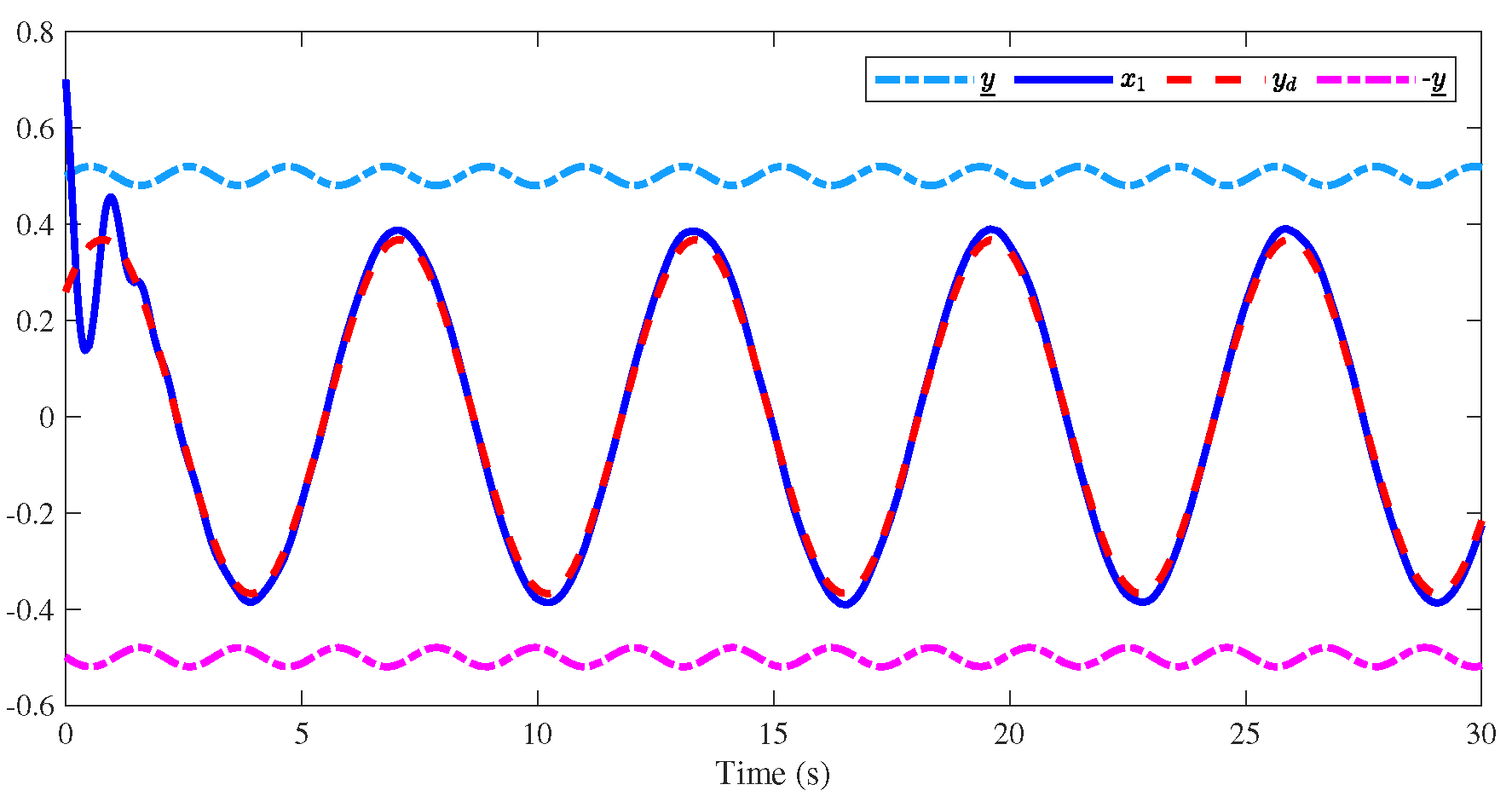
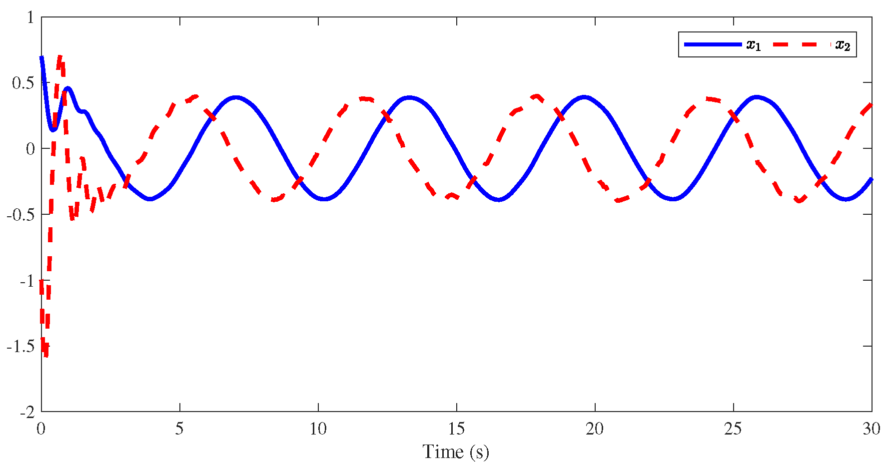
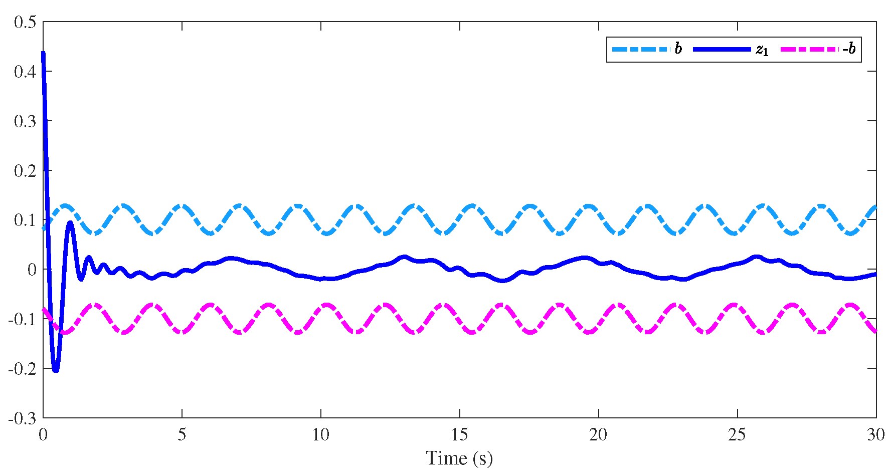
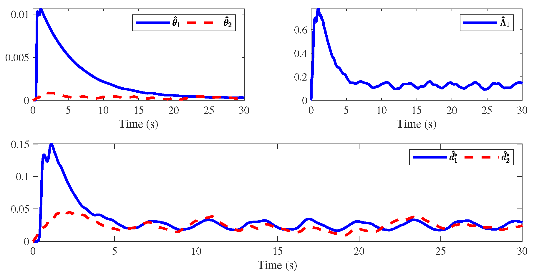
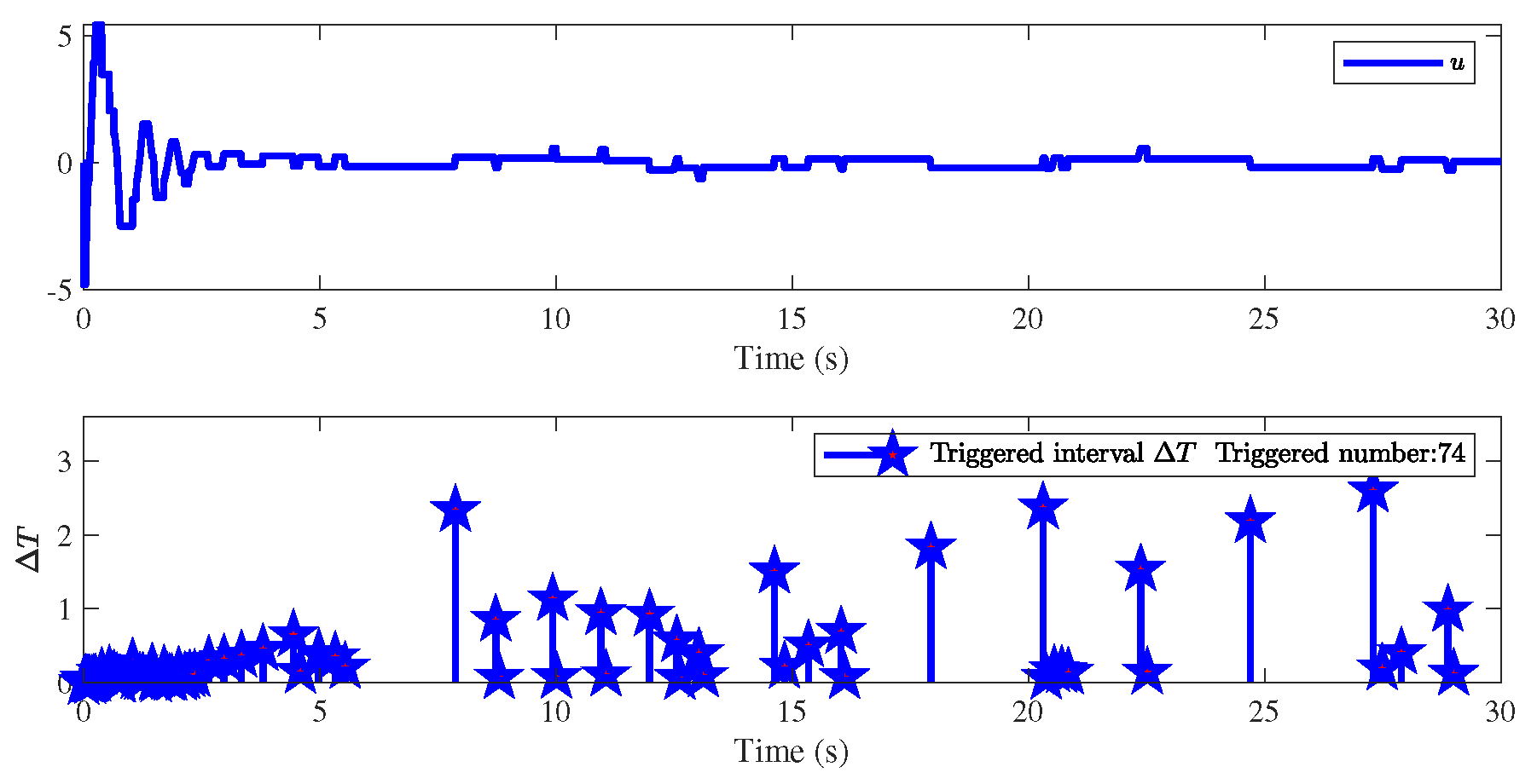
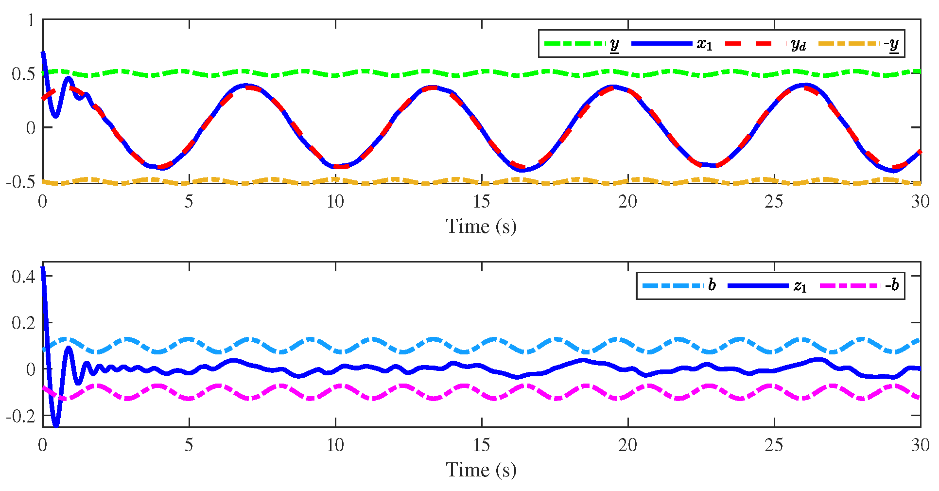
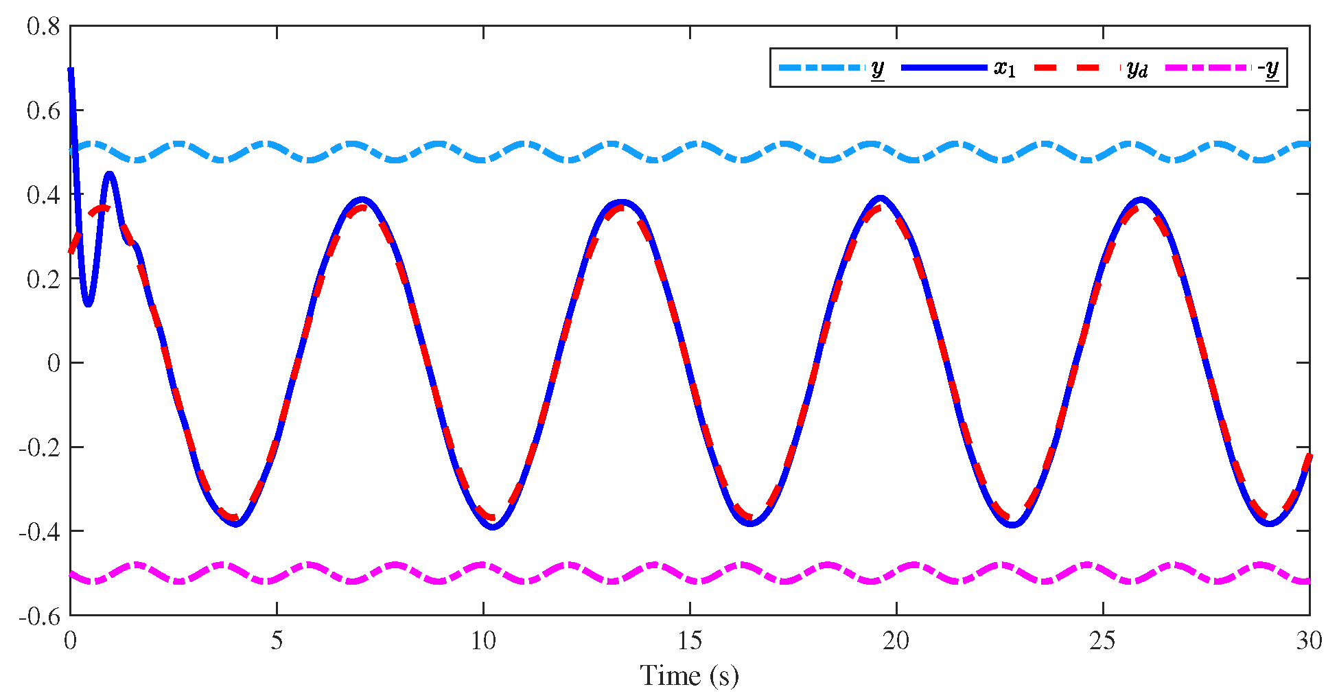
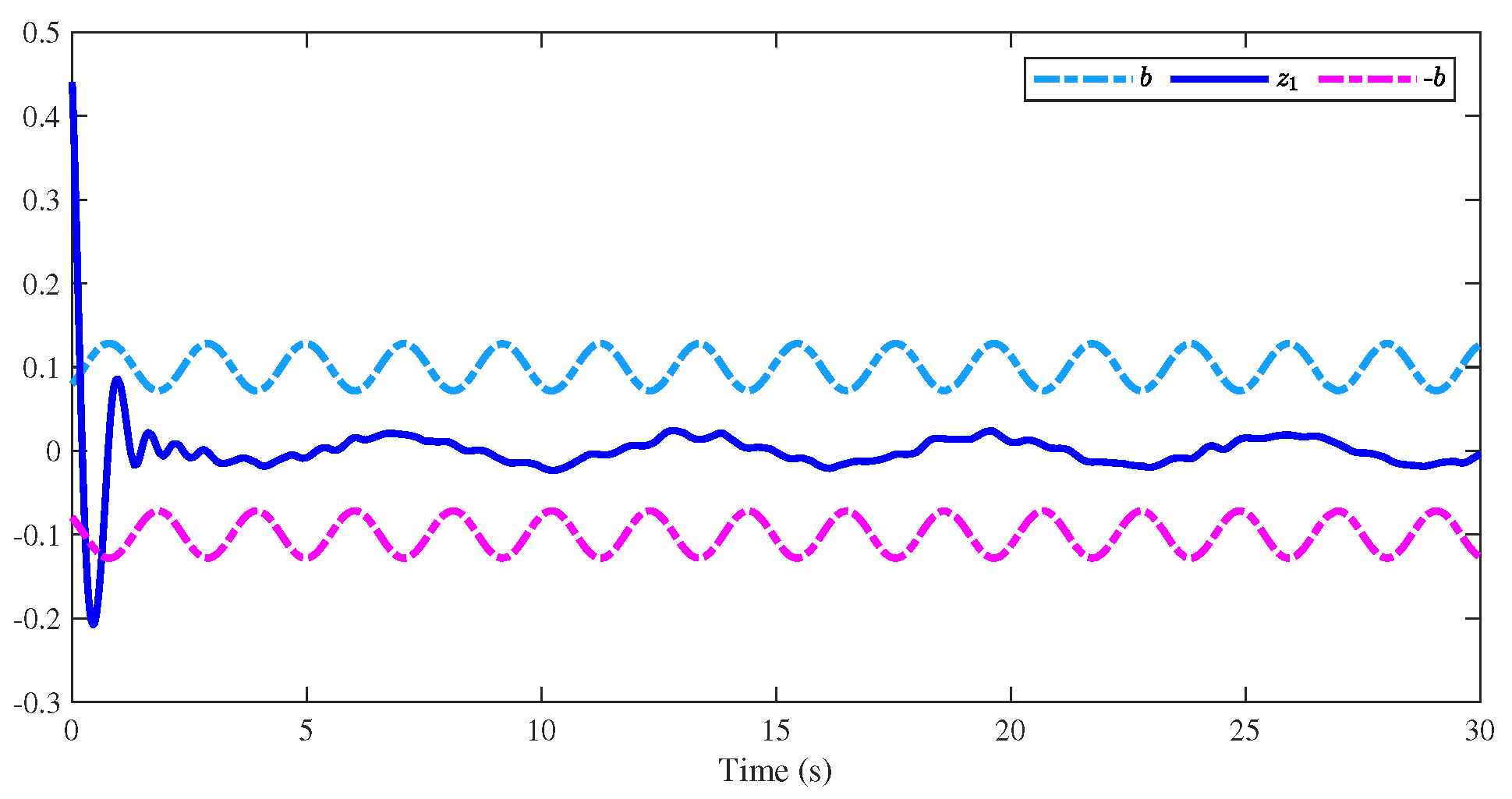
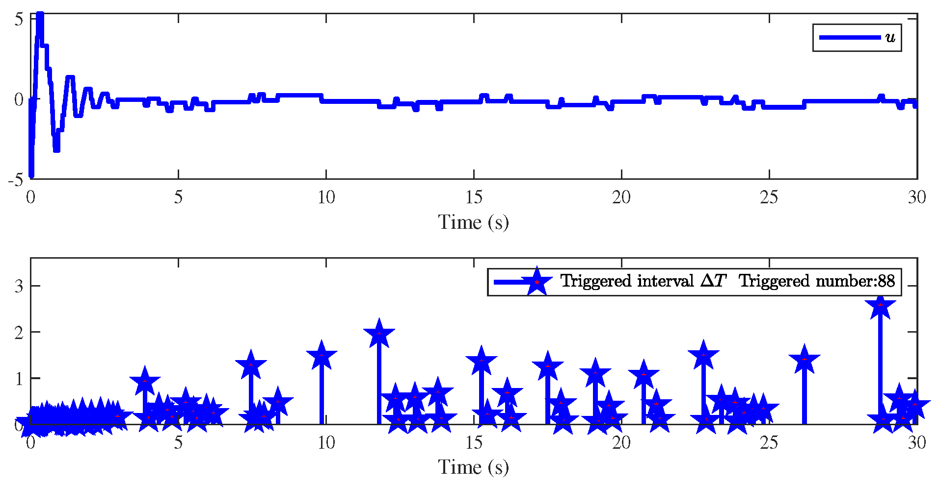
The defined parameter settings are described in Table 1, and the illustrative results are shown in Figure 2, Figure 3, Figure 4, Figure 5 and Figure 6. Figure 2 displays the curves of the system output x 1 and the reference signal y d , which be limited in the time-varying constraints within a preset time T c = 2 s , even though the constraint is violated at the initial time. Then, it can be observed that the system has good tracking performance. Figure 3 shows the trajectories of the state variables x 1 , x 2 . Besides, it can be seen from Figure 4 that tracking error z 1 fluctuates to a small neighborhood of the origin in a predefined-time interval T ( 2 T d ) 1 q = 6.6 s under the enveloped curves ( b ( t ) , b ( t ) ) , which implies that the controlled system can reach a steady state before the predefined-time T . Figure 5 illustrates that the trajectories of adaptive parameters θ ^ i , d ^ i , Λ ^ 1 , and we can easily obtain that they are bounded. At last, Figure 6 shows the actual controller u, the event-triggered time interval Δ T = t k + 1 t k and triggered number, and it is demonstrated that the proposed event-triggered method can save communication resources effectively. Therefore, from the above simulation results, it can be obtained that the proposed control scheme ensures the dynamic response speed of the controlled system as well as the convergence accuracy of the state tracking error, which confirms its effectiveness successfully.
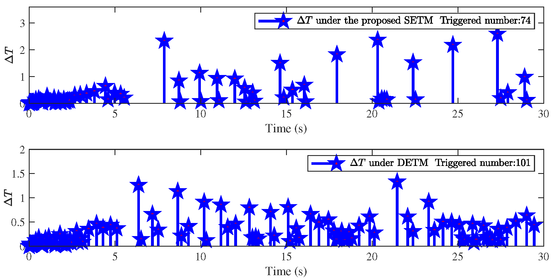
To demonstrate the superiority of the proposed approach, some comparison results are illustrated in Figure 7 and Figure 8. Figure 7 shows the triggered interval Δ T under different ETMs. It can be easily observed from Figure 7 that the update frequency of control signal can be effectively reduced by adopting the proposed switching event-triggered mechanism (SETM) compared with the single dynamic event-triggered mechanism (DETM) proposed in [40] under o 1 = 1.2 and ρ = 0.15 , which also reflects that less communication consumption can be ensured. Furthermore, the traditional fractional-order filter (FOF) developed in [39] and the FO predefined-time filter (FOPTF) proposed in [22] are employed to further show the differences between the filters. With the same conditions except for the design parameter β = 0.5 , the filtering errors under the designed filter and the FOF are demonstrated in Figure 8. While Figure 9 shows the filtering errors and actual input u between the proposed filter and the filter by the sign function with l 1 = 0.2 , l 2 = 0.6 , τ = 1 . It is obvious that the sign function will bring serious chattering to the control input u. According to Figure 8 and Figure 9, one can obtain that better performance can be guaranteed by the provided improved filter. In addition, the external disturbances d 1 ( t ) = 0.2 sin ( π t 2 ) and d 2 ( t ) = sin ( 1.5 t ) are considered in the simulation to verify the robustness of the designed control scheme against the disturbances like measurement noise and larger perturbations in practical scenarios. It can be obtained from Figure 10 that the tracking error still can converge to a small neighborhood of zero within a predefined time interval while obeying the predefined constraints, which also implies that the proposed control algorithm has good robustness against external disturbances.
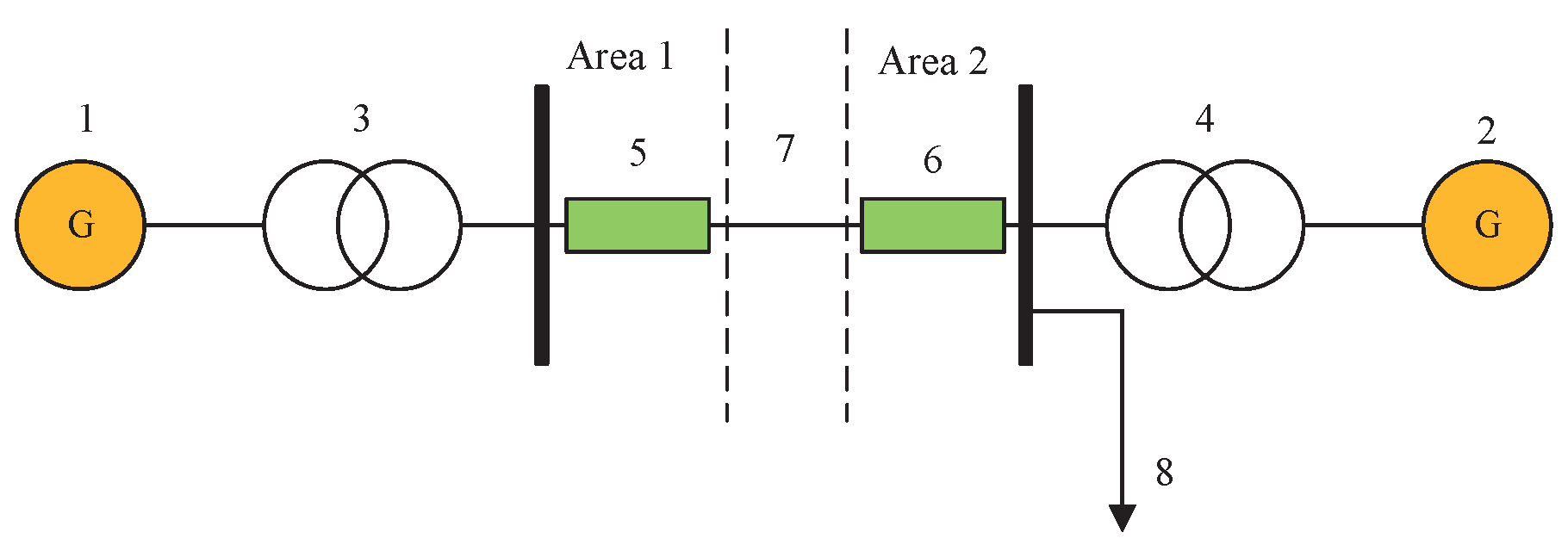
Application Example: The single-machine-infinite bus (SMIB) power system model is a powerful tool for dynamic analysis and control design of power systems, which is widely used in the design of control algorithms [30,41]. For example, by considering system uncertainties and external disturbances, the control strategies designed under the model can be used to improve the stability and enhance the robustness of the power system. Then, the FO model of the SMIB power system model as shown in Figure 11 is considered, which can be described as
D t q 0 C φ ¯ 0 = ω ¯ 0 , D t q 0 C ω ¯ 0 = F ¯ 0 L ¯ 0 ω ¯ 0 P ¯ max L ¯ 0 sin ( φ ¯ 0 ) + P m L 0 + P a L 0 cos ( ε ¯ 0 t ) + u ( t ) ,
where F ¯ 0 , L ¯ 0 , P ¯ a , P ¯ max , P ¯ m are the parameters in the system. φ ¯ 0 is relative angle and ω ¯ 0 is angular frequency between equivalent generators in two areas and ε 0 is a constant. In this study, we define [ x 1 , x 2 ] = [ φ ¯ 0 , ω ¯ 0 ] , f 2 ( x ) = F ¯ 0 ω ¯ 0 / L ¯ 0 P ¯ max sin ( φ ¯ 0 ) / L ¯ 0 + P ¯ max / L ¯ 0 + P a cos ( ε ¯ 0 t ) / L 0 , (67) can be rewritten as
D t q 0 C x 1 = x 2 + 0.1 sin ( t ) D t q 0 C x 2 = ( 1 + x 1 2 ) u ( t ) 0.02 x 2 sin ( x 1 ) + 0.2 + 0.2593 cos ( ε ¯ 0 t ) + 0.1 sin ( 0.5 t )
where q = 0.95 , F ¯ 0 / L ¯ 0 = 0.02 , P ¯ max / L ¯ 0 = 1 , P m / L 0 = 0.2 , P a / L 0 = 0.2593 , g 2 ( x ¯ 2 ) = 1 + x 1 2 , ε ¯ 0 = 1 , d 1 ( t ) = 0.1 sin ( t ) , d 2 ( t ) = 0.1 sin ( 0.5 t ) .
The selection of the design parameters and initial values can be found in Example 1. The simulation results are shown in Figure 12, Figure 13, Figure 14, Figure 15 and Figure 16. Figure 12 reveals the trajectories of the system output x 1 and reference signal y d , which show that good tracking performance can be obtained under the proposed control scheme. Figure 13 gives the curves of the state varies x 1 , x 2 . Subsequently, Figure 14 shows the curve of the tracking error z 1 under the constraint conditions ( b ( t ) , b ( t ) ) , which implies that the system tracking error can converge to a desired error range and have the predefined time stability performance. Figure 15 plots the trajectories of adaptive parameters θ ^ i , d ^ i , and Λ ^ 1 , which can be concluded that their boundedness can be guaranteed. Figure 16 depicts the profile of actual controller u and the time interval Δ T = t k + 1 t k and triggered number of triggered events. From the above, it can be concluded that the provided control algorithm is effective. Besides, it should be noted that the proposed method is applicable for the scenario where the system output is free from constraints initially but constrained some time after system operation, which has significant value in practice.

5. Conclusions

In this article, an adaptive fuzzy predefined-time control solution for FONSs with time-varying deferred constraints has been studied. By utilizing the time-varying BLF and a shifting function, the issue of output constraints under the completely unknown initial conditions has been solved, and the constraints condition will still be adhered to after a predetermined settling time, even if they are transgressed initially. Meanwhile, a switching threshold event-triggered mechanism strategy was proposed to save communication resources and preclude the Zeno behavior. Furthermore, by aid of the predefined-time stability criterion, the proposed control scheme can guarantee that all the signals involved are bounded and that tracking error converges to a small residual set in a predefined time. Finally, the effectiveness of the developed control algorithm has been confirmed by two simulation examples. Considering that asymmetric time-varying constraints are universal in actual situations, developing a fuzzy adaptive control scheme for FONSs with deferred asymmetric time-varying constraints will be one of our future work.

Author Contributions

Writing—original draft preparation, L.X. and S.S.; writing—review and editing, S.S. and X.S.; supervision, X.S. and I.T.; funding acquisition, S.S. and X.S. All authors have read and agreed to the published version of the manuscript.

Funding

This work was supported in part by the National Natural Science Foundation of China under Grant 62203153 and 62473130, in part by the Joint Fund of Science and Technology R&D Plan of Henan Province for Young Scientists under Grant 235200810105, in part by the Top Young Talents in Central Plains under Grant Yuzutong (2021) 44, in part by the Key Scientific Research Projects of Higher Education Institutions in Henan Province under Grant 22A413001, and in part by the Technology Innovative Teams in University of Henan Province under Grant 23IRTSTHN012.

Data Availability Statement

Data are contained within the article.

Conflicts of Interest

The authors declare no conflicts of interest.

References

  1. Tejado, I.; Pérez, E.; Valério, D. Fractional calculus in economic growth modeling of the group of seven. Fract. Calc. Appl. Anal. 2019, 22, 139–157. [Google Scholar] [CrossRef]
  2. Wei, Y.; Tse, P.W.; Yao, Z.; Wang, Y. Adaptive backstepping output feedback control for a class of nonlinear fractional order systems. Nonlinear Dyn. 2016, 86, 1047–1056. [Google Scholar] [CrossRef]
  3. Liu, H.; Pan, Y.; Li, S.; Chen, Y. Adaptive fuzzy backstepping control of fractional-order nonlinear systems. IEEE Trans. Syst. Man Cybern. Syst. 2017, 47, 2209–2217. [Google Scholar] [CrossRef]
  4. Lin, C.; Chen, B.; Shi, P.; Yu, J. Necessary and sufficient conditions of observer-based stabilization for a class of fractional-order descriptor systems. Syst. Control Lett. 2018, 112, 31–35. [Google Scholar] [CrossRef]
  5. Zhang, X.; Huang, W. Adaptive Neural Network Sliding Mode Control for Nonlinear Singular Fractional Order Systems with Mismatched Uncertainties. Fractal Fract. 2020, 4, 50. [Google Scholar] [CrossRef]
  6. Zouari, F.; Ibeas, A.; Boulkroune, A.; Cao, J.; Arefi, M.M. Adaptive neural output-feedback control for nonstrict-feedback time-delay fractional-order systems with output constraints and actuator nonlinearities. Neural Netw. 2018, 105, 256–276. [Google Scholar] [CrossRef] [PubMed]
  7. Ma, Z.; Ma, H. Adaptive fuzzy backstepping dynamic surface control of strict-feedback fractional-order uncertain nonlinear systems. IEEE Trans. Fuzzy Syst. 2020, 28, 122–133. [Google Scholar] [CrossRef]
  8. Zhan, Y.; Sui, S.; Tong, S. Adaptive fuzzy decentralized dynamic surface control for fractional-order nonlinear large-scale systems. IEEE Trans. Fuzzy Syst. 2022, 30, 3373–3383. [Google Scholar] [CrossRef]
  9. Song, S.; Park, J.H.; Zhang, B.; Song, X. Observer-based adaptive hybrid fuzzy resilient control for fractional-order nonlinear systems with time-varying delays and actuator failures. IEEE Trans. Fuzzy Syst. 2021, 29, 471–485. [Google Scholar] [CrossRef]
  10. Bi, W.; Wang, T.; Yu, X. Fuzzy adaptive decentralized control for nonstrict-feedback large-scale switched fractional-order nonlinear systems. IEEE Trans. Cybern. 2022, 52, 8887–8896. [Google Scholar] [CrossRef]
  11. Mendel, J. Computing derivatives in interval type-2 fuzzy logic systems. IEEE Trans. Fuzzy Syst. 2004, 12, 84–98. [Google Scholar] [CrossRef]
  12. Zadeh, L.A. The concept of a linguistic variable and its application to approximate reasoning. Inf. Sci. 1975, 8, 199–249. [Google Scholar] [CrossRef]
  13. Hwang, J.H.; Kwak, H.J.; Park, J.T. Adaptive interval type-2 fuzzy sliding mode control for unknown chaotic system. Nonlinear Dyn. 2011, 63, 491–502. [Google Scholar] [CrossRef]
  14. Jafari, A.A.; Mohammadi, S.M.A.; Naseriyeh, M.H. Adaptive type-2 fuzzy backstepping control of uncertain fractional-order nonlinear systems with unknown dead-zone. Appl. Math. Model. 2019, 69, 506–532. [Google Scholar] [CrossRef]
  15. Shao, S.; Chen, M.; Zheng, S.; Lu, S.; Zhao, Q. Event-triggered fractional-order tracking control for an uncertain nonlinear system with output saturation and disturbances. IEEE Trans. Neural Netw. Learn. Syst. 2022, 35, 5857–5869. [Google Scholar] [CrossRef]
  16. Tang, L.; He, K.; Liu, Y. Adaptive output feedback fuzzy event-triggered control for fractional-order nonlinear switched systems. IEEE Trans. Fuzzy Syst. 2023, 31, 3459–3469. [Google Scholar] [CrossRef]
  17. Zhang, H.; Cai, Y.; Wang, Y.; Su, H. Adaptive bipartite event-triggered output consensus of heterogeneous linear multiagent systems under fixed and switching topologies. IEEE Trans. Neural Netw. Learn. Syst. 2020, 31, 4816–4830. [Google Scholar] [CrossRef] [PubMed]
  18. Wang, L.; Dong, J. Adaptive fuzzy consensus tracking control for uncertain fractional-order multiagent systems with event-triggered input. IEEE Trans. Fuzzy Syst. 2022, 30, 310–320. [Google Scholar] [CrossRef]
  19. Cui, M.; Tong, S. Event-triggered predefined-time output feedback control for fractional-order nonlinear systems with input saturation. IEEE Trans. Fuzzy Syst. 2023, 31, 4397–4409. [Google Scholar] [CrossRef]
  20. Song, X.; Sun, P.; Song, S.; Stojanovic, V. Finite-time adaptive neural resilient DSC for fractional-order nonlinear large-scale systems against sensor-actuator faults. Nonlinear Dyn. 2023, 111, 12181–12196. [Google Scholar] [CrossRef]
  21. Wu, W.; Tong, S. Observer-based fixed-time adaptive fuzzy consensus DSC for nonlinear multiagent systems. IEEE Trans. Cybern. 2023, 53, 5881–5891. [Google Scholar] [CrossRef] [PubMed]
  22. Xie, S.; Chen, Q.; Yang, Q. Adaptive fuzzy predefined-time dynamic surface control for attitude tracking of spacecraft with state constraints. IEEE Trans. Fuzzy Syst. 2022, 31, 2292–2304. [Google Scholar] [CrossRef]
  23. Li, Y.; Liu, Y.; Tong, S. Observer-based neuro-adaptive optimized control of strict-feedback nonlinear systems with state constraints. IEEE Trans. Neural Netw. Learn. Syst. 2022, 33, 3131–3145. [Google Scholar] [CrossRef]
  24. Song, S.; Zhang, B.; Song, X.; Zhang, Z. Neuro-fuzzy-based adaptive dynamic surface control for fractional-order nonlinear strict-feedback systems with input constraint. IEEE Trans. Syst. Man Cybern. Syst. 2021, 50, 3575–3586. [Google Scholar] [CrossRef]
  25. Pishro, A.; Shahrokhi, M.; Sadeghi, H. Fault-tolerant adaptive fractional controller design for incommensurate fractional-order nonlinear dynamic systems subject to input and output restrictions. Chaos Solut. Fractals 2022, 157, 111930. [Google Scholar] [CrossRef]
  26. Tee, K.P.; Ren, B.; Ge, S.S. Control of nonlinear systems with time-varying output constraints. Auotomatica 2011, 47, 2511–2516. [Google Scholar] [CrossRef]
  27. Sun, J.; Yi, J.; Pu, Z. Fixed-time adaptive fuzzy control for uncertain nonstrict-feedback systems with time-varying constraints and input saturations. IEEE Trans. Fuzzy Syst. 2022, 30, 1114–1128. [Google Scholar] [CrossRef]
  28. Song, Y.; Zhou, S. Tracking control of uncertain nonlinear systems with deferred asymmetric time-varying full state constraints. Automatica 2018, 98, 314–322. [Google Scholar] [CrossRef]
  29. Wang, A.; Liu, L.; Qiu, J.; Feng, G. Event-triggered adaptive fuzzy output-feedback control for nonstrict-feedback nonlinear systems with asymmetric output constraint. IEEE Trans. Cybern. 2022, 52, 712–722. [Google Scholar] [CrossRef]
  30. Wang, Q.; Pan, Y.; Cao, J.; Liu, H. Adaptive fuzzy echo state network control of fractional-order large-scale nonlinear systems with time-varying deferred constraints. IEEE Trans. Fuzzy Syst. 2024, 32, 632–648. [Google Scholar] [CrossRef]
  31. Chen, M.; Li, Y.; Wang, H.; Peng, K.; Wu, L. Adaptive fixed-time tracking control for nonlinear systems based on finite-time command filtered backstepping. IEEE Trans. Fuzzy Syst. 2023, 31, 1604–1613. [Google Scholar] [CrossRef]
  32. Yang, X.; Cao, J.; Liu, H.; Huang, C.; Xue, G. Composite adaptive fuzzy bipartite consensus of fractional-order multiagent systems with a switched event-triggered mechanism. ISA Trans. 2024, 148, 224–236. [Google Scholar] [CrossRef] [PubMed]
  33. Podlubny, L. Fractional Differential Equations; Academic: New York, NY, USA, 1998. [Google Scholar]
  34. Li, A. Convexity preserving interpolation. Comput. Aided Geom. Des. 1999, 16, 127–147. [Google Scholar] [CrossRef]
  35. Munoz-Vazquez, A.J.; Sánchez-Torres, J.D.; Jimenez-Rodriguez, E.; Loukianov, A.G. Predefined-time robust stabilization of robotic manipulators. IEEE/ASME Trans. Mechatron. 2019, 24, 1033–1040. [Google Scholar] [CrossRef]
  36. Liu, Y.; Zhang, H.; Sun, J.; Wang, Y. Event-triggered adaptive finite-time containment control for fractional-order nonlinear multiagent systems. IEEE Trans. Cybern. 2022, 54, 1250–1260. [Google Scholar] [CrossRef]
  37. Wang, T.; Zhang, X.; Li, Y. Type-2 fuzzy adaptive output feedback saturation control for photovoltaic grid-connected power systems. Int. J. Control Autom. Syst. 2021, 19, 2759–2768. [Google Scholar] [CrossRef]
  38. Li, Y.; Tong, S. A bound estimation approach for adaptive fuzzy asymptotic tracking of uncertain stochastic nonlinear systems. IEEE Trans. Cybern. 2022, 52, 5333–5342. [Google Scholar] [CrossRef]
  39. You, X.; Shi, M.; Guo, B.; Zhu, Y.; Lai, W.; Dian, S.; Liu, K. Event-triggered adaptive fuzzy tracking control for a class of fractional-order uncertain nonlinear systems with external disturbance. Chaos Solut. Fractals 2022, 161, 112393. [Google Scholar] [CrossRef]
  40. Wang, X.; Xia, J.; Zhang, N.; Yu, M.; Guo, X. Dynamic event-triggered adaptive control for uncertain nonlinear switched systems based on MDADT method. Int. J. Control Autom. Syst. 2023, 21, 84–93. [Google Scholar] [CrossRef]
  41. Liang, Z.; Gao, J. Chaos in a fractional-order single-machine infinite-bus power system and its adaptive backstepping control. Int. J. Mod. Nonlinear Theory Appl. 2016, 5, 122–131. [Google Scholar] [CrossRef]
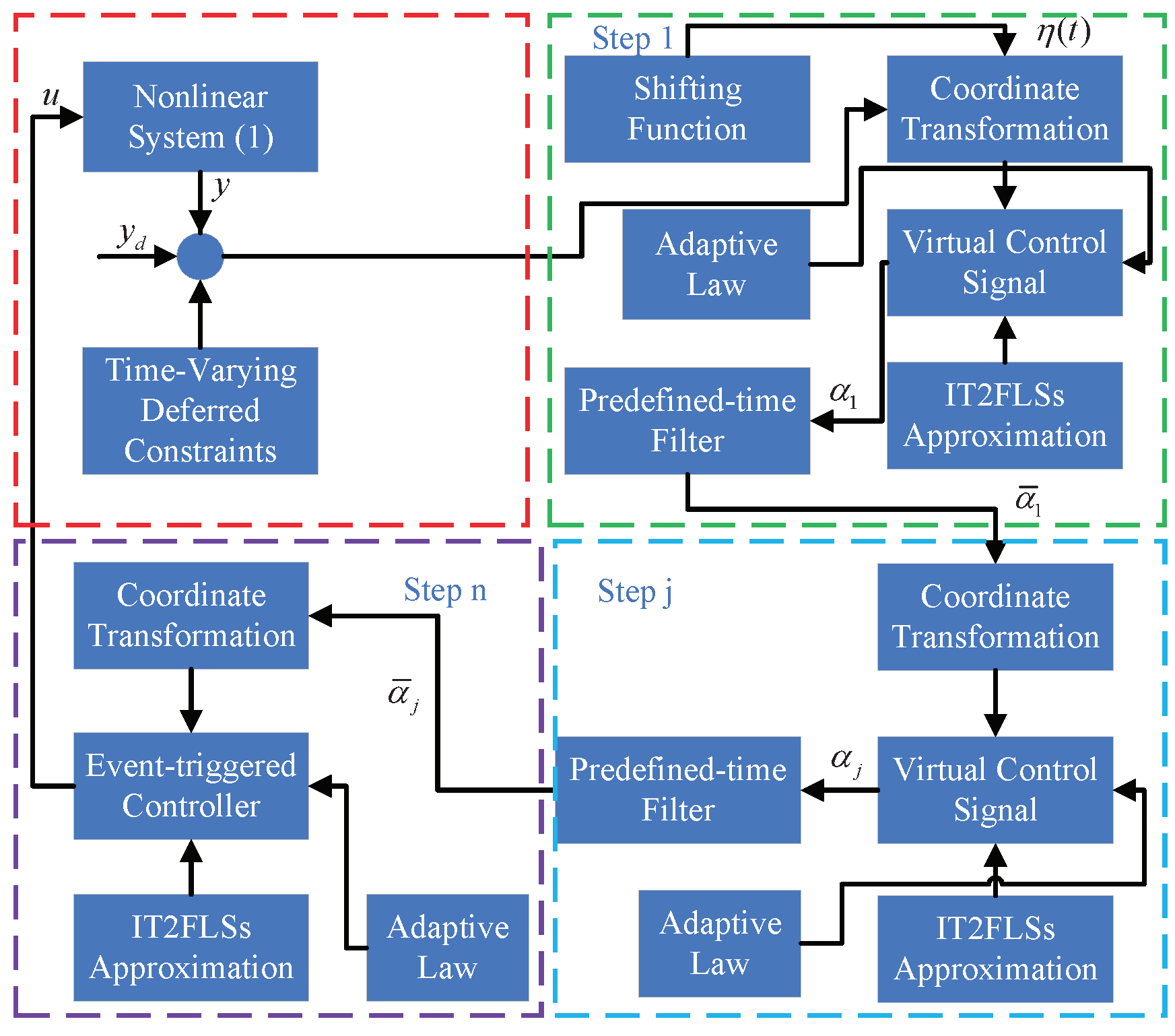
Figure 1. Block diagram of the proposed control scheme.
Fractalfract 08 00613 g001
Figure 2. Trajectory of x 1 and y d .
Fractalfract 08 00613 g002
Figure 3. Trajectory of state variables x 1 and x 2 .
Fractalfract 08 00613 g003
Figure 4. Tracking error z 1 .
Fractalfract 08 00613 g004
Figure 5. Adaptive parameters θ ^ 1 , θ ^ 2 , Λ ^ 1 , d ^ 1 , d ^ 2 .
Fractalfract 08 00613 g005
Figure 6. Actual input u and triggered interval Δ T = t k + 1 - t k .
Fractalfract 08 00613 g006
Figure 7. Triggered interval Δ T = t k + 1 - t k under different ETMs.
Fractalfract 08 00613 g007
Figure 8. Filtering error under different filters.
Fractalfract 08 00613 g008
Figure 9. Filtering error and actual input u under different filters.
Fractalfract 08 00613 g009
Figure 10. Tracking performance under larger perturbations.
Fractalfract 08 00613 g010
Figure 11. Single-machine-infinite bus power system: 1 and 2 denote equivalent generators; 3 and 4 represent transformers; 5, 6, and 7 are considered circuit breakers and tie line between two areas, respectively; 8 is local load.
Fractalfract 08 00613 g011
Figure 12. Trajectory of x 1 and y d .
Fractalfract 08 00613 g012
Figure 13. Trajectory of state variable x 1 and x 2 .
Fractalfract 08 00613 g013
Figure 14. Tracking error z 1 .
Fractalfract 08 00613 g014
Figure 15. Adaptive laws θ ^ 1 , θ ^ 2 , Λ ^ 1 , d ^ 1 , d ^ 2 .
Fractalfract 08 00613 g015
Figure 16. Actual input u and triggered interval Δ T = t k + 1 - t k .
Fractalfract 08 00613 g016
Table 1. The design parameters.
The Initial Conditions
x 1 ( 0 ) = 0.7 , x 2 ( 0 ) = 1 , Λ ^ 1 ( 0 ) = 0 , m ( 0 ) = 0.3 ,
θ ^ 1 ( 0 ) = θ ^ 2 ( 0 ) = d ^ 1 ( 0 ) = d ^ 2 ( 0 ) = 0 .
The Design Parameters
k = 10 , c 1 = 0.1 , c 2 = 0.2 , ς = 0.01 , ϖ = 0.1 exp [ 0.001 t ] ,
m 1 = 0.15 , m 2 = 0.2 , n 1 = λ 1 = λ 2 = 0.5 , χ = 0.1 , σ = 8 49 ,
T d = 3 s , δ 1 = 0.3 , δ 2 = 0.1 , δ 3 = 0.5 , δ 4 = 0.01 , o = 0.1 ,
δ 5 = δ 6 = 1.2 , δ 7 = 0.5 , D = 15 , T c = 2 s .
The Membership Functions
̲ H ¯ 1 m = 0.8 exp 1 2 Δ i a i m z ̲ i m 2 , ¯ H ¯ 1 m = exp 1 2 Δ i a i m z ¯ i m 2 ,
Δ 1 = [ x 1 , z 1 , b , ξ ] T , Δ 2 = [ x 1 , x 2 ] T , a 1 m = a 2 m = 0 , ± 0.1 , ± 0.2 ,
z ̲ 1 m = z ¯ 1 m = [ 4 , 4.5 , 2 , 2 ] T , z ̲ 2 m = z ¯ 2 m = [ 4 , 4.5 ] T , m = 1 , 2 , , 5 .
Disclaimer/Publisher’s Note: The statements, opinions and data contained in all publications are solely those of the individual author(s) and contributor(s) and not of MDPI and/or the editor(s). MDPI and/or the editor(s) disclaim responsibility for any injury to people or property resulting from any ideas, methods, instructions or products referred to in the content.