Article

An Approximation Method for Fractional-Order Models Using Quadratic Systems and Equilibrium Optimizer

Department of Electrical and Electronics Engineering, Faculty of Engineering and Natural Sciences, Malatya Turgut Ozal University, Malatya 44200, Turkey
Fractal Fract. 2023, 7(6), 460; https://doi.org/10.3390/fractalfract7060460
Submission received: 27 April 2023 / Revised: 25 May 2023 / Accepted: 31 May 2023 / Published: 3 June 2023

Abstract

:
System identification is an important methodology used in control theory and constitutes the first step of control design. It is known that many real systems can be better characterized by fractional-order models. However, it is often quite complex and difficult to apply classical control theory methods analytically for fractional-order models. For this reason, integer-order models are generally considered in classical control theory. In this study, an alternative approximation method is proposed for fractional-order models. The proposed method converts a fractional-order transfer function directly into an integer-order transfer function. The proposed method is based on curve fitting that uses a quadratic system model and Equilibrium Optimizer (EO) algorithm. The curve fitting is implemented based on the unit step response signal. The EO algorithm aims to determine the optimal coefficients of integer-order transfer functions by minimizing the error between general parametric quadratic model and objective data. The objective data are unit step response of fractional-order transfer functions and obtained by using the Grünwald-Letnikov (GL) method in the Fractional-Order Modeling and Control (FOMCON) toolbox. Thus, the coefficients of an integer-order transfer function most properly can be determined. Some examples are provided based on different fractional-order transfer functions to evaluate the performance of the proposed method. The proposed method is compared with studies from the literature in terms of time and frequency responses. It is seen that the proposed method exhibits better model approximation performance and provides a lower order model.

1. Introduction

A physical system where the orders of the derivatives are any real number in its differential equation is called a fractional-order system. In recent years, there has been a strong interest in control systems whose mathematical models are expressed by fractional differential equations [1]. Such control systems are called fractional-order control systems. In practice, models of many systems can be described using fractional-order differential equations because systems that are defined by fractional-order describe the real-world more accurately [2]. Therefore, modeling a real-world system in fractional-order yields better results than classical integer-order modeling [3]. For example, viscoelastic materials, electromechanical processes, long transmission lines, dielectric polarizations, colored noise, cardiac behavior, bioengineering problems, and chaos are modelled by fractional-order differential equations [4,5,6,7,8,9]. However, many calculations in fractional-order control systems are quite complex and difficult due to the long memory effect [10]. For example, analytical time responses of fractional-order transfer functions are not possible, except in special cases, such as half derivatives [11]. Moreover, some classical control theory computations, such as State-Space form, Root-Locus and Routh-Hurwitz analysis, are not suitable for fractional-order systems. Classical control theory calculations are based on integer-order systems. Therefore, studies of the integer-order approximation of a fractional process are very important, provided the approximation is accurate [12].
In the absence of analytical solutions, approximations or numerical methods are used for the above-mentioned computations. Many methods have been developed for the approximate time response computation. Some of the numerical based methods are the Grünwald-Letnikov (GL) method in the FOMCON toolbox [13], the Fourier Series Method (FSM), the Inverse Fourier Transform Method (IFTM), and Mittag-Leffler and Gamma functions [14,15,16]. Integer-order approximation-based methods are Continuous Fraction Expansion (CFE), Oustaloup’s, Carlson’s, Matsuda’s, and Chareff’s methods [16,17,18,19,20,21,22,23]. In addition to these methods, Stabilty Boundary Locus (SBL) fitting and its modified version, M-SBL fitting, and time response-based curve fitting, have been used in recent years [24,25,26,27]. Although there are many numerical methods, integer-order approximation methods are frequently preferred because they produce an integer-order transfer function. Thus, all control theory computation can be directly applied to the approximate integer-order transfer function. However, integer-order approximation methods mentioned above are operator-based methods ( s α , α R ), and it is necessary to use higher-order approximations to increase accuracy. Namely, the methods produce higher order approximate integer-order transfer functions for higher accuracy. Calculations with very high order transfer function structures can cause computational errors in control system analysis and are not preferred. The differences between the proposed method and the literature are delineated in the examples. In the literature, there are operator-based approximations that give rise to undesirable higher order approximate transfer functions, which complicate calculation. However, the proposed method results in maximum fifth order transfer functions due to direct approximation. Additionally, error margins are much smaller in time response analysis of the proposed method compared to the existing literature.
Casagrande et al. proposed an integer-order approximation using the interpolation technique in the Loewner framework [28]. An approximation procedure by means of integer-order state-space models is presented in [29]. R. Mansouri proposed a method, which deals with the fractional approximation of systems by integer reduced models [30]. Two other methods for simulating a fractional dynamical system in state space form are presented in [31]. Mohammed Saleh suggested a technique, which is related to the use of rational approaches in fractional-order systems and practical applications of controllers [32]. In [33], researchers proposed and offered an algorithm for a method of approximation useful in robust controller synthesis. Abdelaziz et al. contributed to the literature by presenting a stable approximation method for fractional-order systems based on the Gray Wolf Optimizer hybridized with the Cuckoo Search Algorithm (GWO-CS) in [34]. Apart from these studies, to overcome difficulties induced by operator-based approximations, some direct approximation methods have been proposed by the researchers. The studies are generally based on model reduction, optimization, and algorithms. Some of the most common studies include Particle Swarm Optimization (PSO) [35], the Genetic Algorithm (GA) [36], and Colliding Bodies Optimization (CBO) [37].
The main purpose of this study is to calculate the direct integer-order approximation of a fractional-order transfer function without using operator-based approximation methods. The contributions of this study to the literature are listed below.
  • This study is the first to use a curve fitting method in the time domain using a quadratic standard model structure and EO optimizer. The proposed method allows us to achieve integer approximations with a lower order model and smaller margin of error. Thus, using the proposed method, classical control theory computations, such as State-Space form, Root-Locus and Routh-Hurwitz analysis, can be easily implemented.
  • Using the proposed direct method, an integer-order approximate transfer function is achieved with a maximum of five orders. Additionally, lower-order approximation is obtained compared to operator-based methods.
  • It has been shown that the proposed method is more accurate than operator-based methods in terms of frequency and time response performances.
  • These are applicable to closed-loop fractional-order systems.
The remainder of the study is organized as follows. In Section 2, the EO optimizer is described. In Section 3, the curve fitting algorithm and determination of the approximate transfer function for proposed direct integer-order approximation method is explained. Some illustrative numerical examples using the proposed method are given in Section 4, as well as the calculation of direct approximations of fractional-order transfer functions and their comparison with the methods in the literature are presented. Results are given in Section 5.

2. Equilibrium Optimizer Algorithm

The Equilibrium Optimizer (EO) is a physics-based meta-heuristic optimization algorithm introduced to the literature in 2020 [38]. The idea of this algorithm is based on mimicking the dynamic mass balance on a control volume. EO optimization can be used to solve problems in many studies, such as feature selection, photovoltaic models, medical data and image classification, image segmentation, scheduling, sentiment analysis, and technical problems. In the study, Farmrazzi et al. explained the superiority of the EO algorithm over other optimization methods, such as the Genetic Algorithm (GA), Gravity Search Algorithm (GSA), Grey Wolf Optimizer (GWO), and Particle Swarm Optimization (PSO).
The EO algorithm tries to determine the equilibrium state of the volume on a mass–balance model. The mass–balance equation [39], which is described in the form of the first-order ordinary differential equation, is written as in Equation (1).
V d C d t = Q C e q Q C + G
In Equation (1), the mass change rate in the control volume is defined as V d C / d t , and Q indicates the volume flow rate into or out of the control volume, C e q denotes the concentration at equilibrium, C  is the concentration in the control volume (V), and G denotes the mass generated in this system in the control volume. Here, Equation (2) is obtained when Equation (1) is rearranged by writing λ  instead of Q/V.
d C λ C e q λ C + G / V = d t
For the solution of the ordinary differential equation, Equation (3) is obtained by integrating both sides of the Equation (2).
C 0 C d C λ C e q λ C + G / V = t 0 t d t
As a result, Equation (4) is obtained by solving the ordinary differential equation.
C = C e q + ( C 0 C e q ) F + G λ V ( 1 F )
where; C 0 denotes to the concentration values of the control volume at the initial start time t 0 . λ means flow rate. C represents the solution obtained at the current iteration, and C e q indicates the best solution found so far. The structure given in Equation (4) forms the basis of the EO algorithm, and the EO algorithm performs iterative optimization search, as in the PSO algorithm.
F is the exponential term, and it is computed, as given in Equation (8).
The early step of EO is the random initiation of concentration, as expressed in Equation (5):
C i d = C min + r a n d i d ( C max C min ) i = 1 , 2 , 3 , N   and   d = 1 , 2 , 3 , D
where; N is the number of particles in the population, D is the number of dimensions, C i d is the initial concentration vector for each particle, C max and C min represent the upper and lower bound of the optimization variables, respectively, and r a n d d i is a random vector between [ 0 , 1 ] .
C e q , p o o l is called equilibrium pool. It consists of five elements and is shown in Equation (6). The value C e q ( a v e ) is the average of four best-so-far candidates.
C e q , p o o l = { C e q ( 1 ) , C e q ( 2 ) , C e q ( 3 ) , C e q ( 4 ) , C e q ( a v e ) }
C e q ( a v e ) = C e q ( 1 ) + C e q ( 2 ) + C e q ( 3 ) + C e q ( 4 ) 4
When the optimization is finished, all particles are updated with the same number of updates relative to all candidate solutions. The main concentration values are updated using Equation (8):
F = exp [ λ ( t t 0 ) ]
where; λ in Equation (8) denotes a random vector between [ 0 , 1 ] , t denotes the time and decreases, depending on the number of iterations [40]. t and t 0 are computed by Equations (10) and (11), respectively.
t = ( 1 I t e r M a x _ I t e r ) ( α I t e r M a x _ I t e r )
t 0 = 1 λ ln ( β s i g n ( r 0.5 ) [ 1 e λ t ] ) + t
Equation (11) is determined by substituting t0 in Equation (8), and it is the equation that enables the algorithm to reach the optimal value.
F = β s i g n ( r 0.5 ) [ e λ t 1 ]
The generation rate, G , is one of the important roles in EO, and it improves the algorithm’s ability to work or to use. The mathematical model of G is given in Equation (12).
G = G 0 e k ( t t 0 )
where; k represents the attenuation constant, and G 0 is the initial value. For restricting the random variables, suppose that k = λ , and utilize the formerly derived exponential expression. Generation rate G is calculated by using Equation (13).
G = G 0 e λ ( t t 0 ) = G 0 F
where; G 0 is computed by Equation (14).
G 0 = G C P ( C e q λ C ) G C P = { 0.5 r 1 r 2 G P 0 r 2 < G P
The G C P is the generation rate control parameter that contains the potential of the generation expression assistance for the update procedure. r 1 and r 2 are random numbers in [ 0 , 1 ] . G P is a specified value, which is called the generation probability. The updating of the individual solution of the EO is given in Equation (15). The flowchart of the EO is presented in Figure 1.
C = C e q + ( C C e q ) F + G λ V ( 1 F )

3. The Methodology of the Proposed Direct Integer-Order Approximation Method

In this section, the block diagram of the proposed direct approximation method and the integral performance criteria that we frequently encounter in optimization calculations will be introduced.

3.1. Block Scheme for Curve Fitting Computation with the EO

The block diagram of the proposed direct approximation method and the integral performance criteria that we frequently encounter in optimization calculations are as follows.
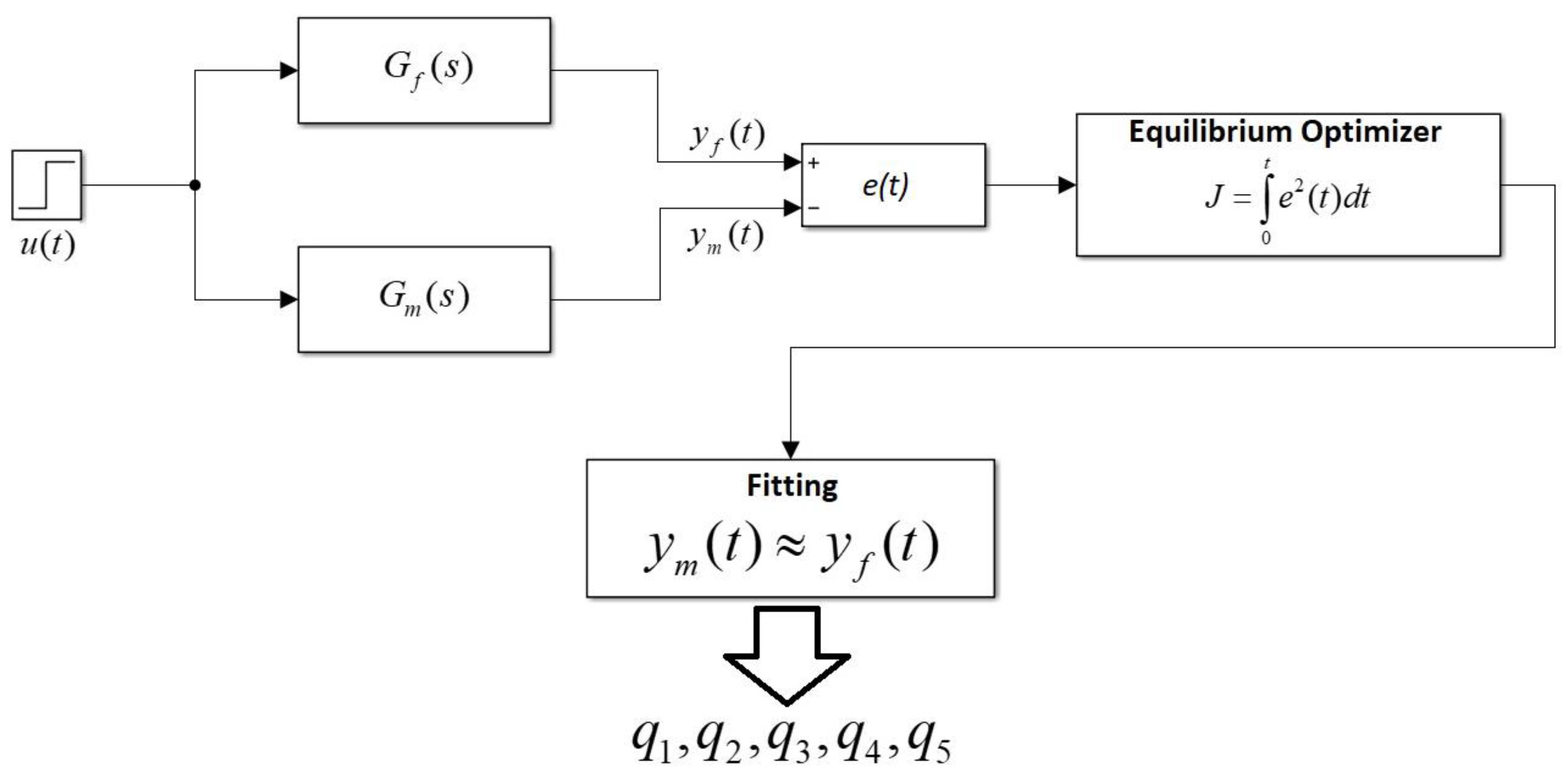
In the diagram, a unit step signal, u(t), is applied to the inputs of the fractional-order transfer function and proposed model transfer function. The unit step time response data of the fractional transfer function defined in the form of Equation (16) are calculated with the GL method in the time step interval Δ t = 0.01 . Thus, the output y f ( t ) is obtained.
G f ( s ) = b m s β m + b m 1 s β m 1 + + b 0 s β 0 a n s α n + a n 1 s α n 1 + + a 0 s α 0 { α i , β j } R + { a i ,   b j } R α 0 < α 1 < < α n , β 0 < β 1 < < β m , i = 0 , 1 , 2 n and j = 0 , 1 , 2 m
The standard quadratic systems are common in practice and are the simplest type of dynamical systems to exhibit oscillations. Mass spring damper systems and RLC circuits can be given as examples for these type systems [41]. In fact, many higher-order systems may be approximated as second-order systems [42].
The canonical form of the second-order differential equation is defined, as in Equation (17).
y ¨ + 2 ζ ω n y ˙ + ω n 2 y = ω n 2 u
The canonical second-order transfer function has the following form in Equation (18), in which it has two poles and no zeros.
Y ( s ) U ( s ) = ω n 2 s 2 + 2 ζ ω n s + ω n 2
In Equation (17), u denotes the input, y denotes the output, ζ is the damping ratio, and ω n is the natural frequency. The unit step response of a standard quadratic transfer function is written in the time domain, as in Equation (19).
y ( t ) = 1 e ( ς ω n t ) ( cos ( ω n ( 1 ζ 2 ) t ) + ( ζ / ( 1 ζ 2 ) ) sin ( ω n ( 1 ζ 2 ) t ) )
Equation (19) can be written in generalized form as Equation (20), and it is proposed as a model transfer function for the curve-fitting computation. Thus, the error function is written as e(t) = [yf(t) − ym(t)], and it is used as a fitness function in the EO optimizer.
y m ( t ) = 1 e q 1 t cos ( q 2 t ) q 3 e q 4 t s i n ( q 5 t )
The Laplace transform of Equation (20) is given in Equation (21), where q 1 , q 2 , q 3 , q 4 , and q 5 are the unknown coefficients. Equation (21) is an integer-order approximate transfer function to be obtained after using the EO curve fitting.
Y m ( s ) = 1 s s + q 1 ( s + q 1 ) 2 + q 2 2 q 3 q 5 ( s + q 4 ) 2 + q 5 2
The structure of the transfer function with integer-order given in Equation (23) can be obtained from Equation (21). Depending on the structure of the fractional-order transfer function, the order of Gm(s) can be 5 or less at the maximum.
G m ( s ) = s Y m ( s )
G m ( s ) = n 4 s 4 + n 3 s 3 + n 2 s 2 + n 1 s + n 0 s 5 + m 4 s 4 + m 3 s 3 + m 2 s 2 + m 1 s + m 0 { m i , n i } R , i = 0 , 1 , 2 n

3.2. Determination of the Proposed Model-Transfer-Function Parameters

The coefficients of optimal model transfer function can be obtained by minimizing the error signal by using integral performance criteria. Integral performance criteria are defined as cost functions in optimization algorithms and provide minimization. First, the integral of the square of the error (ISE) and the integral of the absolute value of the error (IAE) performance criteria were used by Graham and Lathrop [43] in 1953. Then, the absolute value of the time-weighted error (ITAE) and the integral of the square of the time-weighted error (ITSE) were developed by [44]. Some performance criteria and their mathematical expressions in the literature are given in Equations (25)–(30) [45].
  • The Integral of Error (IE) is defined as:
I E = 0 t e ( t ) d t
  • The Mean Square Error (MSE) is defined as:
M S E = 0 t e 2 ( t ) d t t
  • The Integral Squared Error (ISE) is defined as:
I S E = 0 t e 2 ( t ) d t
  • The Integral Absolute Error (IAE) is defined as:
I A E = 0 t | e ( t ) | d t
  • The Integral of the Square of the Time-Weighted Error (ITSE) is defined as:
I T S E = 0 t t e 2 ( t ) d t
  • The Integral of the Absolute of the Time-Weighted Error (ITAE) is defined as:
I T A E = 0 t t | e ( t ) | d t
In the diagram in Figure 2, the cost function is defined as the square of the difference between the unit step responses of fractional-order and the model transfer function. This definition of the cost function (30) is the ISE performance criterion.
J = 0 t e 2 ( t ) d t
In the optimization, various initial values, such as the lower and upper bounds of the model transfer function parameters, the maximum number of iterations, and the number of particles, are entered. Then, the algorithm is run for the cost function adapted to the EO algorithm. In this paper, the particle number is selected as 30, and the maximum iteration number is selected as 200. The lower and upper bounds of the transfer function coefficients are considered in the range of [ 5 , 5 ] . The error signal is obtained by subtracting the parametric unit step response of the model transfer function from the unit step response of the fractional-order transfer function. Then, the error is updated according to the new values, and the cost function gradually decreases. Thus, the cycle continues until the desired criterion is met. Optimal model transfer function parameters (q1, q2, q3, q4, q5) are obtained when the desired criterion is met. Thus, the proposed direct integer-order approximation of the fractional-order transfer function is calculated, as in the form of Equation (23).

4. Numerical Examples

In this section, numerical examples are given, and the advantages of the proposed method over classical integer-order approximations are presented, as well as the use of the proposed method in closed-loop fractional-order control systems, and the comparison of two articles in the literature on direct integer-order approximation is given.

4.1. Examining the Proposed Method in Various Transfer Function Forms

Example 1:
Let us obtain the integer-order approximation of the fractional-order transfer function given in (31).
G ( s ) = 0.6 s 1.24 + 0.7 0.5 s 4.16 + 3.2 s 3.28 + 4.4 s 2.12 + 5.5 s 1.57 + 1.2 s 0.94 + 1
The fractional-order transfer function given in Equation (31) includes the terms of fractional derivative operators s 0.12 , s 0.16 , s 0.24 , s 0.28 , s 0.57 , and s 0.94 . Approximations of each fractional derivative term can be easily calculated by using Continuous Fraction Expansion (CFE), Oustaloup’s method, and Matsuda’s method, which are very common in the literature, as well as M-SBL methods, which were developed using the SBL technique. Finally, by substituting these approximations in Equation (31), the integer-order approximation of the G ( s ) is obtained. Since Oustaloup can produce odd-order approximations, comparisons are made on odd-order approximations. The integer-order approximations of G ( s ) calculated using the 3rd order approximations of the CFE, Oustaloup, Matsuda, and M-SBL methods are given in Equations (32)–(35), respectively. It can be seen from Equations (32)–(35) that G ( s ) is obtained from 22 degrees for the 3rd order operator-based approximation. If we use fifth order approximations for each fractional derivative term, the order of the approximate transfer function will be 34. As observed, higher order approximations of the fractional derivative terms result in much higher orders in the total transfer function.
G C F E ( s ) = 1.463 s 19 + 387.1 s 18 + 2.298 × 10 4 s 17 + 6.228 × 10 5 s 16 + 9.441 × 10 6 s 15 + 8.774 × 10 7 s 14 + 5.264 × 10 8 s 13 + 2.116 × 10 9 s 12 + 5.881 × 10 9 s 12 + 1.158 × 10 10 s 10 + 1.642 × 10 10 s 9 + 1.691 × 10 10 s 8 + 1.261 × 10 10 s 7 + 6.753 × 10 9 s 6 + 2.551 × 10 9 s 5 + 6.653 × 10 8 s 4 + 1.161 × 10 8 s 3 + 1.287 × 10 7 s 2 + 8.161 × 10 5 s + 2.249 × 10 4 0.9019 s 22 + 249.3 s 21 + 1.695 × 10 4 s 20 + 5.442 × 10 5 s 19 + 1.001 × 10 7 s 18 + 1.154 × 10 8 s 17 + 8.814 × 10 8 s 16 + 4.64 × 10 9 s 15 + 1.747 × 10 10 s 14 + 4.853 × 10 10 s 13 + 1.016 × 10 11 s 12 + 1.619 × 10 11 s 11 + 1.958 × 10 11 s 10 + 1.788 × 10 11 s 9 + 1.223 × 10 11 s 8 + 6.245 × 10 10 s 7 + 2.379 × 10 10 s 6 + 6.744 × 10 9 s 5 + 1.405 × 10 9 s 4 + 2.085 × 10 8 s 3 + 2.071 × 10 7 s 2 + 1.225 × 10 6 s + 3.235 × 10 4
G O u s ( s ) = 1.812 s 19 + 465 s 18 + 4.719 × 10 4 s 17 + 2.493 × 10 6 s 16 + 7.534 × 10 7 s 15 + 1.341 × 10 9 s 14 + 1.403 × 10 10 s 13 + 8.601 × 10 10 s 12 + 3.208 × 10 11 s 11 + 7.619 × 10 11 s 10 + 1.193 × 10 12 s 9 + 1.251 × 10 12 s 8 + 8.708 × 10 11 s 7 + 3.856 × 10 11 s 6 + 1.02 × 10 11 s 5 + 1.598 × 10 10 s 4 + 1.492 × 10 9 s 3 + 8.13 × 10 7 s 2 + 2.388 × 10 6 s + 2.918 × 10 4 1.045 s 22 + 285.3 s 21 + 3.148 × 10 4 s 20 + 1.849 × 10 6 s 19 + 6.385 × 10 7 s 18 + 1.346 × 10 9 s 17 + 1.75 × 10 10 s 16 + 1.416 × 10 11 s 15 + 7.353 × 10 11 s 14 + 2.566 × 10 12 s 13 + 6.305 × 10 12 s 12 + 1.118 × 10 13 s 11 + 1.429 × 10 13 s 10 + 1.288 × 10 13 s 9 + 8.016 × 10 12 s 8 + 3.429 × 10 12 s 7 + 1.022 × 10 12 s 6 + 2.08 × 10 11 s 5 + 2.794 × 10 10 s 4 + 2.389 × 10 9 s 3 + 1.238 × 10 8 s 2 + 3.529 × 10 6 s + 4.235 × 10 4
G M a t ( s ) = 2.341 s 19 + 3780 s 18 + 1.045 × 10 6 s 17 + 1.173 × 10 8 s 16 + 6.564 × 10 9 s 15 + 1.935 × 10 11 s 14 + 2.967 × 10 12 s 13 + 2.314 × 10 13 s 12 + 9.979 × 10 13 s 11 + 2.58 × 10 14 s 10 + 4.229 × 10 14 s 9 + 4.509 × 10 14 s 8 + 3.096 × 10 14 s 7 + 1.289 × 10 14 s 6 + 2.919 × 10 13 s 5 + 3.654 × 10 12 s 4 + 2.608 × 10 11 s 3 + 1.058 × 10 10 s 2 + 2.271 × 10 8 s + 2.004 × 10 6 1.234 s 22 + 2024 s 21 + 6.002 × 10 5 s 20 + 7.458 × 10 7 s 19 + 4.751 × 10 9 s 18 + 1.654 × 10 11 s 17 + 3.168 × 10 12 s 16 + 3.332 × 10 13 s 15 + 2.05 × 10 14 s 14 + 7.963 × 10 14 s 13 + 2.096 × 10 15 s 12 + 3.892 × 10 15 s 11 + 5.107 × 10 15 s 10 + 4.614 × 10 15 s 9 + 2.787 × 10 15 s 8 + 1.119 × 10 15 s 7 + 3.062 × 10 14 s 6 + 5.431 × 10 13 s 5 + 5.986 × 10 12 s 4 + 3.999 × 10 11 s 3 + 1.565 × 10 10 s 2 + 3.29 × 10 8 s + 2.866 × 10 6
G M S B L ( s ) = 2.197 s 19 + 3729 s 18 + 1.318 × 10 6 s 17 + 1.957 × 10 8 s 16 + 1.454 × 10 10 s 15 + 5.583 × 10 11 s 14 + 1.054 × 10 13 s 13 + 8.936 × 10 13 s 12 + 3.939 × 10 14 s 11 + 1.013 × 10 15 s 10 + 1.623 × 10 15 s 9 + 1.664 × 10 15 s 8 + 1.075 × 10 15 s 7 + 4.067 × 10 14 s 6 + 7.86 × 10 13 s 5 + 7.903 × 10 12 s 4 + 4.348 × 10 11 s 3 + 1.323 × 10 10 s 2 + 2.094 × 10 8 s + 1.345 × 10 6 1.182 s 22 + 2040 s 21 + 7.659 × 10 5 s 20 + 1.239 × 10 8 s 19 + 1.029 × 10 10 s 18 + 4.577 × 10 11 s 17 + 1.064 × 10 13 s 16 + 1.231 × 10 14 s 15 + 7.873 × 10 14 s 14 + 3.084 × 10 15 s 13 + 8.085 × 10 15 s 12 + 1.485 × 10 16 s 11 + 1.912 × 10 16 s 10 + 1.678 × 10 16 s 9 + 9.733 × 10 15 s 8 + 3.683 × 10 15 s 7 + 9.189 × 10 14 s 6 + 1.406 × 10 14 s 5 + 1.262 × 10 13 s 4 + 6.57 × 10 11 s 3 + 1.943 × 10 10 s 2 + 3.024 × 10 8 s + 1.923 × 10 6
The integer-order approximation of G(s), calculated by the proposed direct approximation method, is obtained as a 4th order approximation, as seen in Equation (36).
G m ( s ) = 0.0027 s 3 + 0.1923 s 2 + 0.1691 s + 0.0481 s 4 + 2.05 s 3 + 1.391 s 2 + 0.3591 s + 0.0687
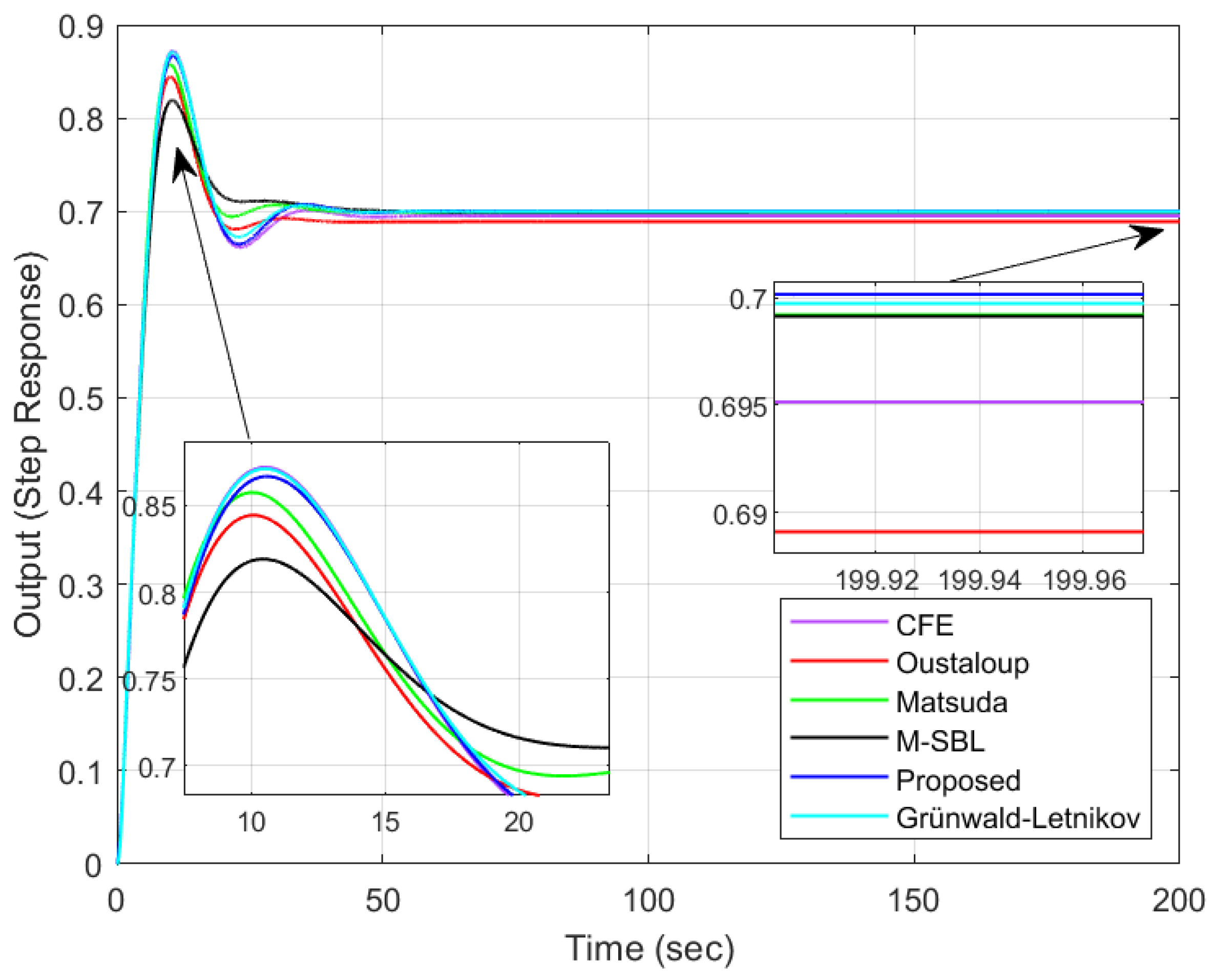
The GL method gives near-accurate results at low step intervals in time response calculations [46]. In this example, the comparisons are based on the GL method, and the step time interval for GL computations is chosen as 0.01. In operator-based approximation methods, the frequency range [0.01, 100] rad/s is preferred. The unit step response of the transfer functions in Equations (32)–(36) and unit step response of G(s) calculated using the GL method are given in Figure 3.
It can be seen, from Figure 3, that, although the transfer function calculated by the proposed direct approximation method is of the 4th order, it gives quite close results to the time response calculated by the GL method. To compare the operator-based approximation and the proposed method, approximations of different orders were obtained, and their errors were calculated. The mean squared errors (MSE) of these approximations, which derived from different orders, are presented in Table 1. Since operator-based approximations are calculated from odd orders in the Oustaloup method, approximations of the first-, third-, and fifth-orders are considered for the Oustaloup method. For the other methods, first-, second-, and third-order operator approximation are considered. The transfer function, Gm(s), calculated with the proposed method, has lower error than the 28th order G(s) obtained by CFE, Matsuda, and M-SBL methods. However, Table 1 shows that these methods have better results than the proposed direct approximation method for 34th-order approximation, except for Oustaloup.
Table 2 shows the time response performance specifications, such as rise time, settling time, peak time, peak value, overshoot, and steady state error of Equations (31)–(36). The unit step response of Equation (31) is directly plotted numerically by the GL method. Unit step responses are plotted using the approximate transfer functions given in Equations (32)–(36). Here, the approximation methods are compared with the GL method. The first thing to notice is that the steady-state error of the proposed direct approximation method is zero. It is observed that the method with the farthest performance specifications is Oustaloup. CFE, one of the operator-based methods, gives the closest result to the performance of the GL method. The transfer function calculated from the 4th degree with the proposed direct approximation method shows acceptable performance compared to the operator-based methods calculated from the 22nd order.
Example 2:
Let us consider an open loop unstable and stable fractional model given in (37) and (39), respectively.
G f ( s ) = 1 0.75 s 2.42 + 1.47 s 0.8 + 3.2
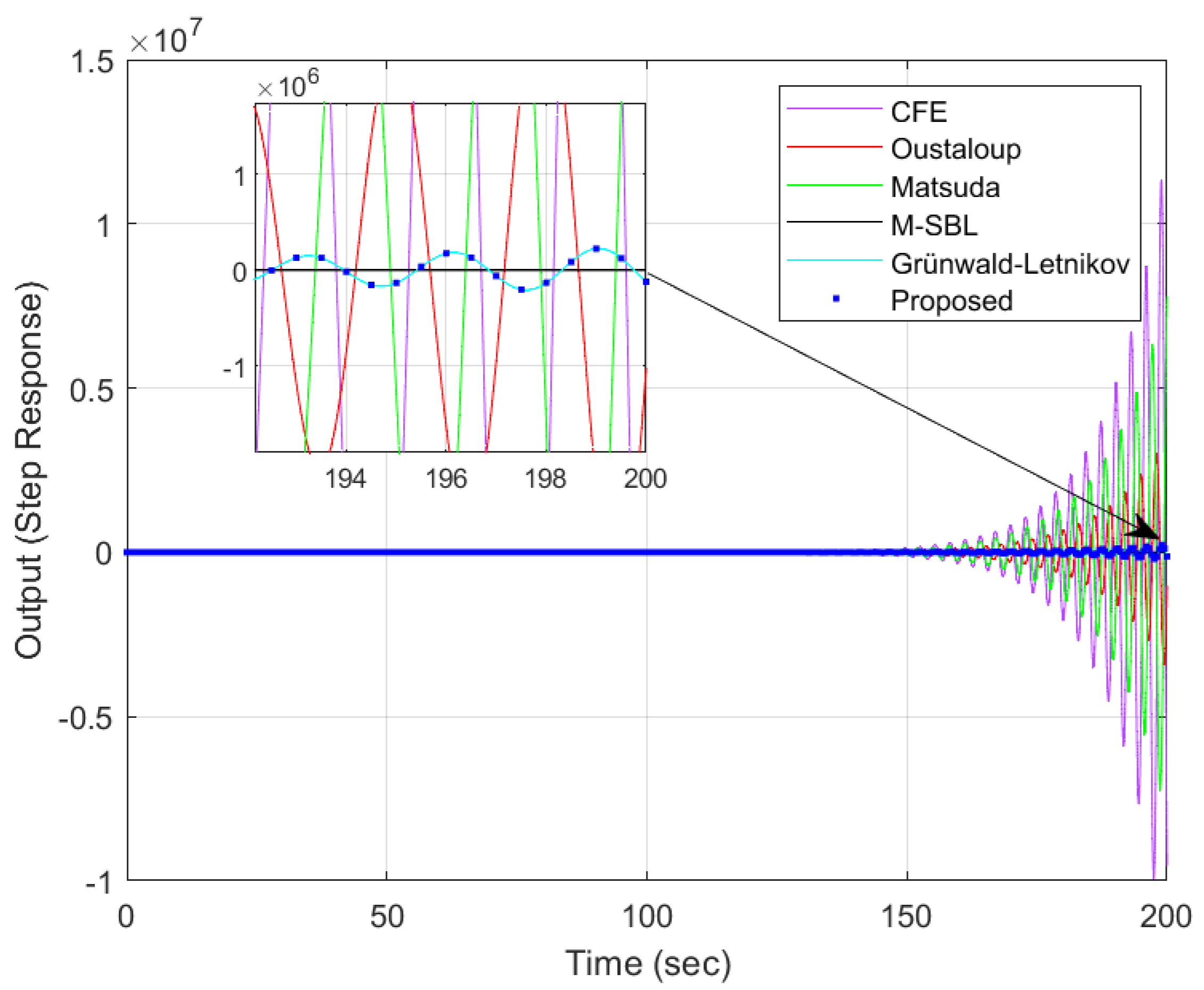
Equation (37) shows an open loop unstable model structure with two fractional-orders. When approximations are calculated with operator-based methods for this unstable model, an 8th-order transfer function is obtained. When the proposed method is used, a 5th-order approximation, such as Equation (38), is calculated. The unit step response performance of the operator-based approximations and the proposed method are given in Figure 4.
G m ( s ) = 0.2980 s 3 + 5.5703 s 2 + 40.1592 s + 182.3607 s 5 + 10.6963 s 4 + 60.4775 s 3 + 167.3740 s 2 + 251.5915 s + 583.2891
The proposed method gives very robust approximations for open loop unstable transfer functions. It is observed from Figure 4 that the proposed method gives the same results as the GL method. Although operator-based methods have 8th-order approximations, it is seen that they have different oscillations. For this example, it was seen that the Oustaloup and M-SBL method gave the closest result among the operator-based methods.
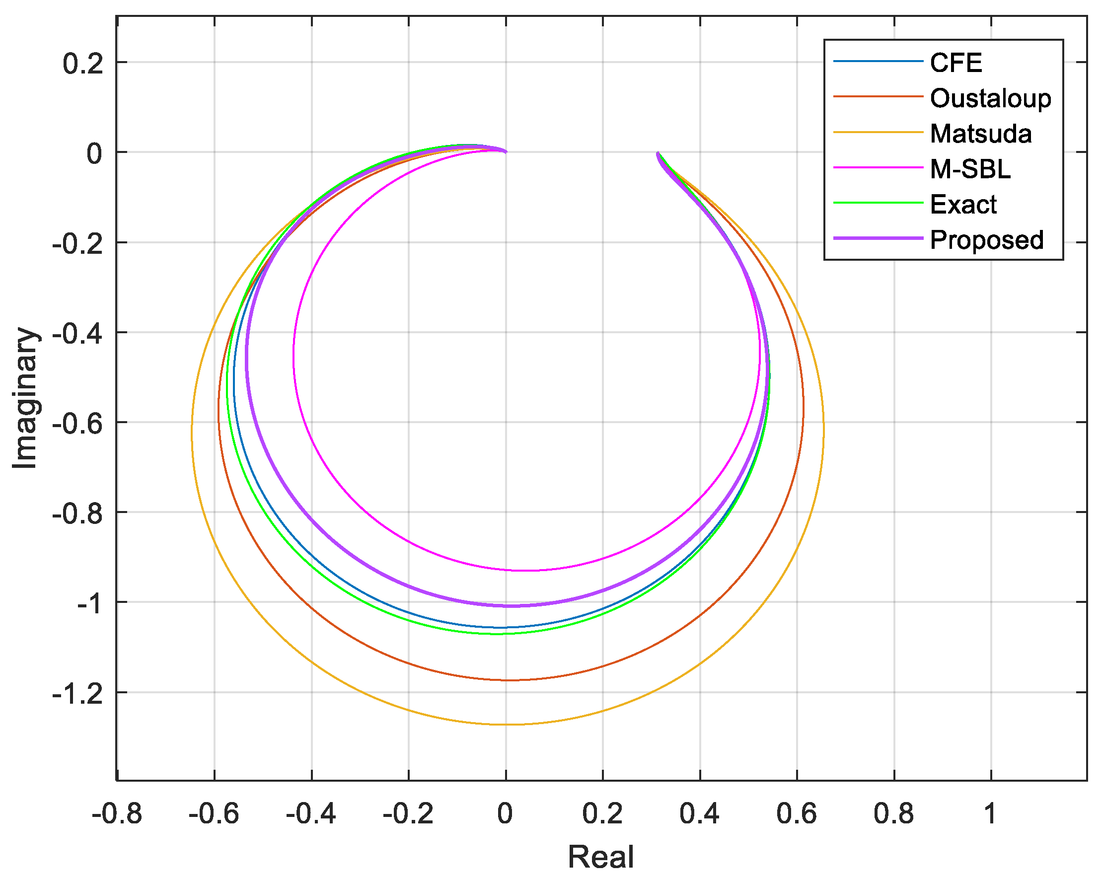
A stable model was obtained by changing the fractional-order term in the middle in the denominator in Equation (37) to 1.35. The approximation calculated with the proposed method for the open loop stable fractional-order model is given in Equation (40). Bode and Nyquist curves for frequency response analysis of this model are given in Figure 5 and Figure 6, respectively.
G f ( s ) = 1 0.75 s 2.42 + 1.47 s 1.35 + 3.2
G m ( s ) = 0.1671 s 3 + 6.4425 s 2 + 4.5125 s + 22.2325 s 5 + 9.0625 s 4 + 14.8300 s 3 + 53.8000 s 2 + 34.4750 s + 71.1500
The phase margin and gain margin values are important points on the bode diagram in control systems. It is seen in Figure 5 that, although the proposed method offers a 5th-degree approximation, it gives near-accurate results in data, such as phase margin and gain margin, compared to operator-based methods. The data measured on the Bode diagram are presented in Table 3. The proposed method is the best result in the phase margin. In the gain margin, it is the second-best result.
Nyquist diagrams of operator-based approximation methods, for the Exact and the Proposed method, are shown in Figure 6. Here, the critical points where the curves intersect the real axis are examined. These points are also given in Table 3. As can be seen, the critical gain value of the CFE method is closer to the exact value. However, the CFE approximation is 8th-order. The proposed approximation is 5th-order, and it is the best result after CFE. Although the proposed method is of low order, it has an acceptable frequency characteristic compared to the other methods.
Example 3:
Examination of the unity feedback control system with the fractional-order controller and the plant. Consider the fractional-order control system given in Figure 7.
In this example, it is shown how to compute integer-order approximation of a closed loop fractional-order control system by using the proposed method. Here, the fractional-order PI controller and plant transfer function are given in Equation (41). Additionally, the open loop transfer function is written, as shown in Equation (42). Thus, the closed loop transfer function can be computed, as shown in Equation (43).
G ( s ) = 1.2 s 0.72 + 1.42 2 s 0.72   and   G ( s ) = 0.64 s 1.17 + 3 1.8 s 1.62 + 0.4 s 1.21 + 2 s 0.58 + 0.42
L ( s ) = C ( s ) G ( s ) = 0.768 s 1.89 + 0.9088 s 1.17 + 3.6 s 0.72 + 4.26 3.6 s 2.34 + 0.8 s 1.93 + 4 s 1.3 + 0.84 0.72
T ( s ) = L ( s ) 1 + L ( s ) = 0.768 s 1.89 + 0.9088 s 1.17 + 3.6 s 0.72 + 4.26 3.6 s 2.34 + 0.8 s 1.93 + 0.768 s 1.89 + 4 s 1.3 + 0.9088 s 1.17 + 4.44 0.72 + 4.26
As seen in (43), T(s) has many fractional-orders, such as 0.89, 0.17, 0.72, 0.34, 0.93, and 0.30. When we use the 3rd-order operator-based approximation methods in this transfer function, the 29th-order integer approximation is obtained. Furthermore, when the 4th-order approximation methods are used, the 38th-order integer approximation is obtained. Namely, operator-based integer-order approximation methods produce very high-order transfer functions. Such higher order transfer functions cannot be suitable for real-world applications. However, when the proposed direct approximation method is used for T(s), 4th-order integer approximation is obtained, as shown in (44).
T m ( s ) = 0.624 s 3 + 1.933 s 2 + 1.697 s + 0.571 s 4 + 2.611 s 3 + 3.362 s 2 + 2.115 s + 0.571
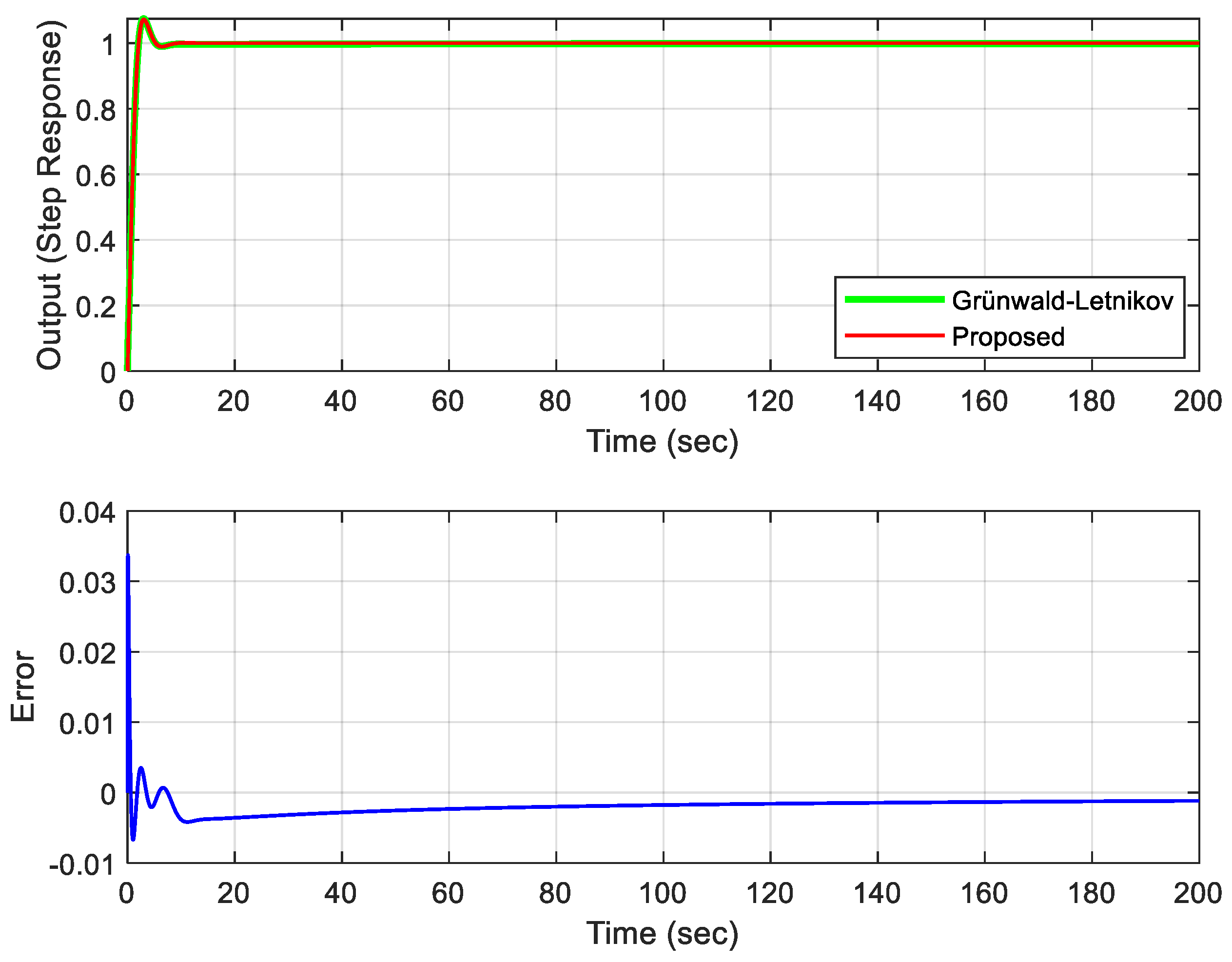
The unit step response and error plot of T ( s ) and T m ( s ) are plotted in Figure 8 for the performance analysis of the proposed method. The error curve was obtained, according to the GL method. As is seen in Figure 8, the error margin of the proposed method is almost zero. Only at the first moment there is a maximum error margin of 0.034. It is shown that a low-order integer approximation is obtained due to the use of the proposed method. It also has a very low margin of error. This example also shows that very complex fractional-order transfer functions, such as T ( s ) , can be directly converted as a low-order integer-order transfer function by using the proposed method. The proposed method is also a helpful tool for applying classical control theory techniques to fractional-order control systems.

4.2. Comparison with Direct Approximation Methods in the Literature

Example 4:
Equation (45) is used widely in the literature for integer-order approximation. Techniques, such as PSO algorithm [35], block pulse functions and generalized operational matrices [47], Oustaloup approximation [48], and integer-order-approximation calculations using different model reduction [49] are often used.
G ( s ) = 1 0.8 s 2.2 + 0.5 s 0.9 + 1
Integer-order approximations of Equation (45) are computed by above methods [35,47,48,49] and are given in Equations (46)–(51), respectively.
G P S O ( s ) = 1 0.1772 s 3 + 0.7329 s 2 + 0.4463 s + 1.0265
G B l o c k _ P u l s e 1 ( s ) = 1 s 2 + 0.327 s + 1.048
G B l o c k _ P u l s e 2 ( s ) = 0.3213 s + 1.525 s 2 + 0.3255 s + 1.571
G B T ( s ) = 0.2121 s + 1.409 s 2 + 0.1838 s + 1.41
G S P A ( s ) = 0.1777 s 2 0.2739 s + 1.437 s 2 + 0.1932 s + 1.438
G H N A ( s ) = 0.1072 s 2 0.3346 s + 1.421 s 2 + 0.1876 s + 1.422
The integer-order approximate transfer function is computed by the proposed method, and the approximate transfer function is shown in Equation (52). Unit step response of the transfer functions is computed by the literature [35,47,48,49], and the proposed methods are superimposed in Figure 9.
G P r o p o s e d ( s ) = 0.8844 s 3 + 1.8085 s 2 + 1.6777 s + 2.1596 s 5 + 1.5691 s 4 + 3.4532 s 3 + 3.8213 s 2 + 2.7957 s + 2.1596
As shown in Figure 9, the proposed method follows the actual system response more accurately than the others. Furthermore, performance characteristics (rise time, settling time, peak time, peak value, overshoot, and integral square error (ISE)) are compared among the methods in Table 4. The proposed method has the closest response to the GL method when compared to transfer functions with positive coefficients. The steady-state error of the transfer function obtained by the proposed method is exact compared to other methods. Three fundamental properties of the proposed method can be observed in Figure 9 and Table 4: it can compute the positive coefficient approximate transfer function, it gives nearly exact results in time response performance characteristics, and it results in the same steady-state-error as GL.
Example 5:
In another study, Oustaloup’s recursive filter and a refined Outsaloup’s filter, examined in [46,48], are considered for integer-order approximations. Integer-order transfer functions are obtained by using the filters. Then, using some model reduction techniques, lower-order transfer functions are obtained by preserving the dominant behavior of higher-order integer transfer functions. One of the applications in [48] is given in Equation (53), and the equation is considered in this paper, also.
G ( s ) = 5 s 2.3 + 1.3 s 0.9 + 1.25
The proposed method offers a 5th-order approximation. For the accuracy of the comparison, the transfer function of order 5 or more is chosen in [48], which is given in Equation (54).
G p a d e 46 ( s ) = 4.334 s 4 + 3.488 s 3 + 0.6366 s 2 + 0.03234 s + 0.0004762 s 6 + 1.504 s 5 + 2.152 s 4 + 1.091 s 3 + 0.173 s 2 + 0.008392 s + 0.000121
The fractional-order transfer function in Equation (53) results an integer-order transfer function given in Equation (55) obtained by the proposed method.
G p r o p o s e d ( s ) = 1.2751 s 3 + 15.5456 s 2 + 13.9474 s + 4.7263 s 5 + 3.6807 s 4 + 6.5421 s 3 + 8.0526 s 2 + 5.0702 s + 1.1816
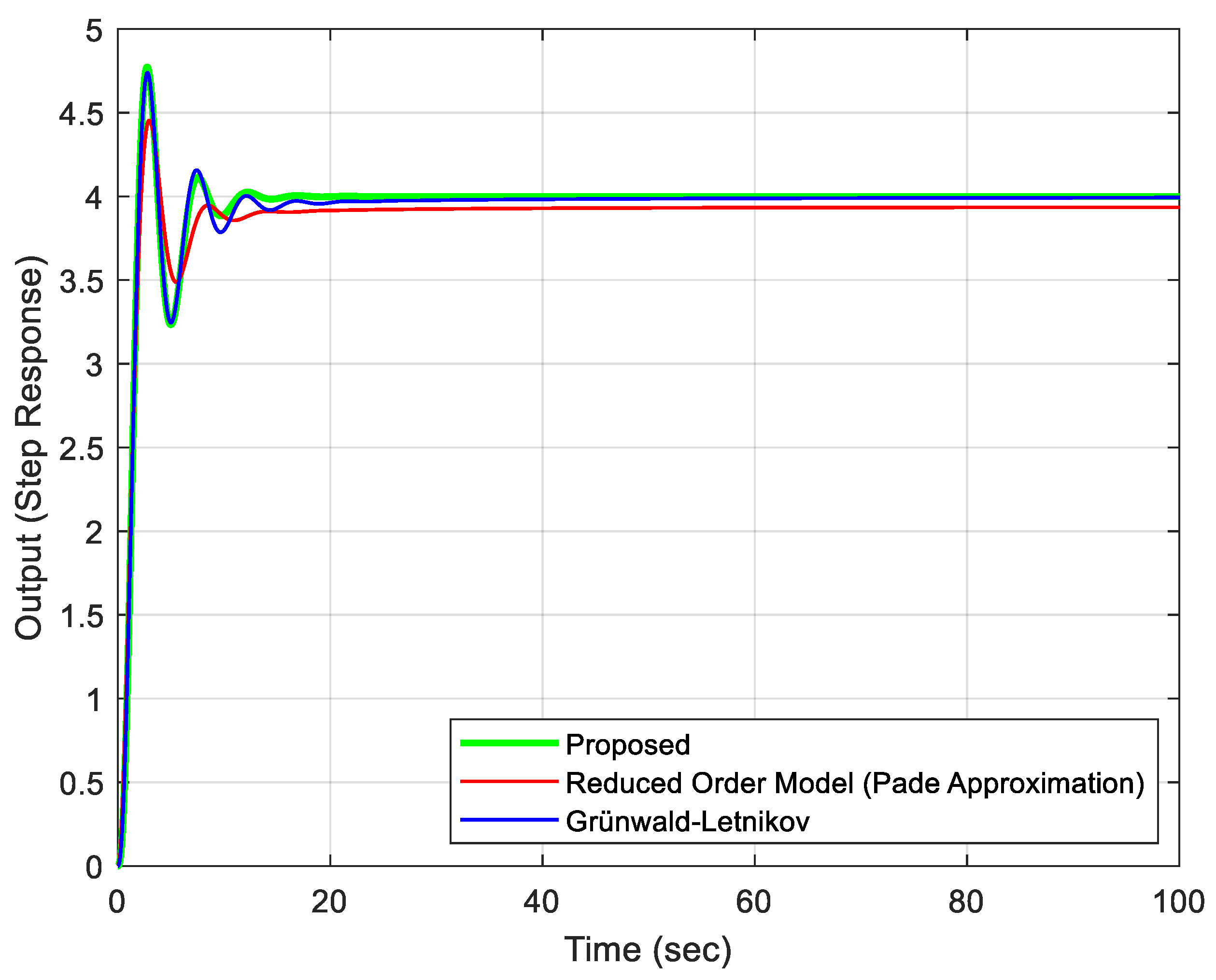
The unit-step-responses of the proposed method, reduced order method, and GL method are superimposed in Figure 10. The proposed method follows the exact method more accurately than the other as shown in Figure 10. Moreover, the order of the approximate-integer-order transfer function computed by the proposed method is less than the order of the approximate-integer-order transfer function in [48].
In Table 5, it is seen that the proposed method is more accurate than the reduced order model given in [48] in terms of performance characteristics, such as rise time, peak time, peak value, overshoot, and steady-state error.
Design of a PID controller for the fractional-order transfer function as in Equation (53) is as follows: Routh-Hurwitz stability criterion cannot be applied for fractional-order transfer functions. However, the Routh-Hurwitz criterion can be successfully applied to the integer-order approximate transfer function G p r o p o s e d ( s ) derived by using the proposed method. Additionally, PID controller design can be done easily using Ziegler-Nichols method. For the design method, the process is taken to closed-loop proportional control ( K ), as in Figure 11, and the closed-loop transfer function of the system is written as Equation (56).
H ( s ) = K G p r o p o s e d ( s ) 1 + K G p r o p o s e d ( s ) H ( s ) = 1.2751 K s 3 + 15.5456 K s 2 + 13.9474 K s + 4.7263 K s 5 + 3.6807 s 4 + ( 6.5421 + 1.2751 K ) s 3 + ( 8.0526 + 15.5456 K ) s 2 + ( 5.0702 + 13.9474 K ) s + ( 1.1816 + 4.7263 K )
Δ ( s ) = s 5 + 3.6807 s 4 + ( 6.5421 + 1.2751 K ) s 3 + ( 8.0526 + 15.5456 K ) s 2 + ( 5.0702 + 13.9474 K ) s + ( 1.1816 + 4.7263 K )
For the characteristic equation given in Equation (57), the Routh-Hurwitz stability criterion method is applied as given in Equation (58). The critical gain K c r and critical frequency ω c r and critical period Tcr of the system are easily calculated using the Routh-Hurwitz method.
s 5 s 4 s 3 s 2 s 1 s 0 | 1 3.6807 A C E F ( 6.5421 + 1.2751 K ) ( 8.0526 + 15.5456 K ) B D 0 0 ( 5.0702 + 13.9474 K ) ( 1.1816 + 4.7263 K ) 0 0 0 0 A = 4.3543 2.9484 K B = 12.6633 K + 4.7491 C = [ ( 45.8353 K 2 + 2.6621 K 17.5832 ) ] [ ( 2.9484 K 4.3543 ) ] D = [ ( 47,263 K + 11,816 ) ( 2.9484 × 10 4 K 4.3543 × 10 4 ) ] [ ( 2.9484 K 4.3543 ) ] E = [ ( 2.9484 K 4.3543 ) ( 3.1076 × 10 34 K 3 7.0154 × 10 33 K 2 + 7.5374 × 10 33 K + 3.0551 × 10 33 ) ] [ ( 1.4742 × 10 32 K 2.1772 × 10 32 ) ( 45.8353 K 2 + 2.6621 K 17.5832 ) ] F = [ ( 47,263 K + 11,816 ) ( 1.4742 × 10 65 K 2.1772 × 10 65 ) ( 45.8353 K 2 + 2.6621 K 17.5832 ) ( 1.5537 × 10 33 K 3 3.5077 × 10 32 K 2 + 3.7687 × 10 32 K + 1.5276 × 10 32 ) ] [ ( 2.9484 K 4.3543 ) ( 2.2917 × 10 33 K 2 + 1.3311 × 10 32 K 8.7916 × 10 32 ) ( 1.5537 × 10 70 K 3 3.5076 × 10 69 K 2 + 3.7687 × 10 69 K + 1.5275 × 10 69 ) ]
In order to calculate the critical gain of the system, it is determined as Kcr = K = 0.5467 by using the Matlab fminsearch command at E = 0 in Equation (58). Using the K gain value, the equations C and D are calculated as 0.8855 and 3.7654 , respectively. Thus, from the auxiliary equation 0.8855s2 + 3.7654 = 0, the critical frequency is obtained as ω c r = 2.0621 rad/s. In this case, the period of the oscillating signal is calculated as Tcr = 3.0470 s. According to the Ziegler-Nichols Method, the parameters of the PID controller are calculated using Equation (59).
C ( s ) = K p ( 1 + 1 τ i s + τ d s ) K p = 0.5882 K c r τ i = 0.5 * T c r τ d = 0.125 T c r
When the critical gain and critical period values are substituted in Equation (59), the PID controller parameters are calculated as K p = 0.3216 , τ i = 1.5235 , and τ d = 0.3809 . Thus, the PID controller transfer function is obtained as Equation (60). Closed-loop unit step responses of G p r o p o s e d ( s ) , G p a d e ( s ) , and G ( s ) , using the PID controller, are presented in Figure 12. The closed-loop unit step response of the fractional transfer function G ( s ) is obtained using the IFTM method. In Figure 12, it is seen that the closed loop unit step response of G p r o p o s e d ( s ) successfully tracks of G ( s ) . This shows that G p r o p o s e d ( s )  is a successful integer-order approximation. It is seen that G p a d e ( s ) , which is the approximation obtained using the Pade method, obviously has higher error.
C ( s ) = 0.3216 + 0.2111 s + 0.1225 s

5. Conclusions

Integer-order approximations are very important for applying classical control theory rules and simulations on fractional-order transfer functions. In this study, an alternative method has been developed to directly obtain the integer-order approximation of fractional-order transfer functions. The proposed method applied to perform an approximation in both open-loop stable and unstable fractional-order transfer functions. The method is based on curve fitting with the EO algorithm, which has been developed in recent years. Operator-based integer-order approximation methods, such as Oustaloup, Matsuda, Carlson, Chareff, etc. can produce very large order transfer functions. The proposed method not only provides a low order transfer function approximation, but also has a lower error margin compared to existing methods with higher order transfer function approximation. It has been shown, in examples, that the proposed method can easily transform a fractional-order transfer function directly to approximate integer-order transfer function. The proposed method produces a maximum 5th-order approximate transfer function. In this way, the computations, such as time response, frequency response, stability analysis, controller design, etc. can be easily performed in control theory. In addition, analytical controller designs can be made by converting the approximate transfer function to standard forms by using model reduction methods. The Routh-Hurwitz stability criterion can be easily applied. In this way, the P/PI/PID controller can be designed using the Ziegler-Nichols method. In addition, the proposed method can be used successfully in closed loop control systems which include both fractional controller and plant. Thus, fractional-order closed-loop control systems can be investigated as an integer-order transfer function. Comparisons with other methods are presented on widely used applications in the literature. In Example 4, among the positive coefficient approximate transfer functions, it is seen that the proposed method is closest to the GL method in performance characteristics, such as rise time, settling time, peak value, overshoot, and steady-state error. In Example 5, a 6th-order integer approximation presented in the literature is compared with the 5th-order integer-order approximation, which was computed using the proposed method. It is seen that the proposed method is closest to the GL method in terms of rise time, peak time, peak value, over-shoot, and steady-state error performance characteristics. In both examples, five of the six performance criteria are very close to the performance criteria of the GL method, which give accurate results. In addition, Example 5, a successful PID controller design has been made using the Routh-Hurwitz stability criterion. It has been understood that the proposed method gives more efficient and accurate results than the methods presented in Examples 4 and 5. This study can be used widely as a more efficient tool in fractional control systems calculations. In addition, the transfer function structure obtained by the proposed method is suitable for electronic circuit implementations, such as fractional-order filter circuit. In the future, the study of the electronic implementations of filters with two fractional-orders on these results can be considered.

Funding

This research received no external funding.

Data Availability Statement

The study did not report any data.

Conflicts of Interest

The authors declare no conflict of interest.

References

  1. Monje, C.A.; Chen, Y.; Vinagre, B.M.; Xue, D.; Feliu-Batlle, V. Fractional-Order Systems and Controls: Fundamentals and Applications; Springer: London, UK, 2010. [Google Scholar] [CrossRef]
  2. Yu, W.; Luo, Y.; Pi, Y. Fractional order modeling and control for permanent magnet synchronous motor velocity servo system. Mechatronics 2013, 23, 813–820. [Google Scholar] [CrossRef]
  3. Das, S. Functional Fractional Calculus for System Identification and Controls; Springer-Verlag: Berlin/Heidelberg, Germany, 2008. [Google Scholar]
  4. Zhao, K. Existence, stability and simulation of a class of nonlinear fractional Langevin equations involving nonsingular Mittag–Leffler kernel. Fractal Fract. 2022, 6, 469. [Google Scholar] [CrossRef]
  5. Rendón, J.E.; Mejía, C.E. Fractional order modeling of a nonlinear electromechanical system. Enfoque UTE 2018, 9, 45–56. [Google Scholar]
  6. Hartley, T.T.; Lorenzo, C.F. Dynamics and control of initialized fractional-order systems. Nonlinear Dyn. 2002, 29, 201–233. [Google Scholar] [CrossRef]
  7. Magin, R.L. Fractional Calculus in Bioengineering; Begell House Inc.: Redding, CT, USA, 2006; Volume 2. [Google Scholar]
  8. Zhang, T.; Xiong, L. Periodic motion for impulsive fractional functional differential equations with piecewise Caputo derivative. Appl. Math. Lett. 2020, 101, 106072. [Google Scholar] [CrossRef]
  9. Zhang, T.; Li, Y. Exponential Euler scheme of multi-delay Caputo–Fabrizio fractional-order differential equations. Appl. Math. Lett. 2022, 124, 107709. [Google Scholar] [CrossRef]
  10. Rauh, A. Exponential Enclosures for the Verified Simulation of Fractional-Order Differential Equations. Fractal Fract. 2022, 6, 567. [Google Scholar] [CrossRef]
  11. Chen, Y.; Petras, I.; Vinagre, B. A list of Laplace and Inverse Laplace Transforms Related to Fractional Order Calculus. 2001, pp. 1–3. Available online: http://ivopetras.tripod.com/foc_laplace.pdf (accessed on 6 January 2023).
  12. Iqbal, A.; Shekh, R.R. A comprehensive study on different approximation methods of Fractional order system. Int. Res. J. Eng. Technol. IRJET 2016, 3, 1848–1863. [Google Scholar]
  13. Tepljakov, A.; Petlenkov, E.; Belikov, J. FOMCON: Fractional-order modeling and control toolbox for MATLAB. In Proceedings of the 2011 18th International Conference on Mixed Design of Integrated Circuits and Systems (MIXDES), Gliwice, Poland, 16–18 June 2011; pp. 684–689. [Google Scholar]
  14. Podlubny, I. Fractional Differential Equations; Academic Press: Cambridge, MA, USA, 1998; Volume 198. [Google Scholar]
  15. Polubny, I. Fractional-order systems and PIλDμ controller. IEEE Trans. Autom. Control. 1999, 44, 208–214. [Google Scholar] [CrossRef]
  16. Atherton, D.P.; Tan, N.; Yüce, A. Methods for computing the time response of fractional-order systems. IET Control. Theory Appl. 2014, 9, 817–830. [Google Scholar] [CrossRef]
  17. Vinagre, B.; Podlubny, I.; Hernandez, A.; Feliu, V. Some approximations of fractional order operators used in control theory and applications. Fract. Calc. Appl. Anal. 2000, 3, 231–248. [Google Scholar]
  18. Krishna, B. Studies on fractional order differentiators and integrators: A survey. Signal Process. 2011, 91, 386–426. [Google Scholar] [CrossRef]
  19. Oustaloup, A.; Levron, F.; Mathieu, B.; Nanot, F.M. Frequency-band complex noninteger differentiator: Characterization and synthesis. IEEE Trans. Circuits Syst. I Fundam. Theory Appl. 2000, 47, 25–39. [Google Scholar] [CrossRef]
  20. Carlson, G.; Halijak, C. Approximation of fractional capacitors (1/s)^(1/n) by a regular Newton process. IEEE Trans. Circuit Theory 1964, 11, 210–213. [Google Scholar] [CrossRef]
  21. Matsuda, K.; Fujii, H. H~ Optimized Wave-Absorbing Control: Analytical and Experimental Results. J. Guid. Control. Dyn. 1993, 16, 1146. [Google Scholar] [CrossRef]
  22. Charef, A.; Sun, H.; Tsao, Y.; Onaral, B. Fractal system as represented by singularity function. IEEE Trans. Autom. Control. 1992, 37, 1465–1470. [Google Scholar] [CrossRef]
  23. Khanra, M.; Pal, J.; Biswas, K. Rational approximation of fractional operator—A comparative study. In Proceedings of the 2010 International Conference on Power, Control and Embedded Systems, Allahabad, India, 29 November–1 December 2010; pp. 1–5. [Google Scholar]
  24. Deniz, F.N.; Alagoz, B.B.; Tan, N.; Atherton, D.P. An integer order approximation method based on stability boundary locus for fractional order derivative/integrator operators. ISA Trans. 2016, 62, 154–163. [Google Scholar] [CrossRef]
  25. Yüce, A.; Tan, N. A New Integer Order Approximation Table for Fractional Order Derivative Operators. In Proceedings of the IFAC 2017 World Congress, Toulouse, France, 9–14 July 2017; pp. 9736–9741. [Google Scholar]
  26. Shrivastava, N.; Varshney, P. Frequency band implementation of non-integer order functions. In Proceedings of the 5th International Conference on Signal Processing and Integrated Networks (SPIN), Noida, India, 22–23 February 2018; pp. 852–857. [Google Scholar]
  27. Deniz, F.N.; Alagoz, B.B.; Tan, N.; Koseoglu, M. Revisiting four approximation methods for fractional order transfer function implementations: Stability preservation, time and frequency response matching analyses. Annu. Rev. Control. 2020, 49, 239–257. [Google Scholar] [CrossRef]
  28. Casagrande, D.; Krajewski, W.; Viaro, U. The Integer–Order Approximation of Fractional–Order Systems in the Loewner Framework. IFAC-PapersOnLine 2019, 52, 43–48. [Google Scholar] [CrossRef]
  29. Krajewski, W.; Viaro, U. A method for the integer-order approximation of fractional-order systems. J. Frankl. Inst. 2014, 351, 555–564. [Google Scholar] [CrossRef]
  30. Mansouri, R.; Bettayeb, M.; Djennoune, S. Optimal reduced-order approximation of fractional dynamical systems. In Proceedings of the AIP Conference Proceedings, Annaba, Algeria, 30 June–2 July 2008; pp. 127–132. [Google Scholar]
  31. Rachid, M.; Maamar, B.; Said, D. Comparison between two approximation methods of state space fractional systems. Signal Process. 2011, 91, 461–469. [Google Scholar] [CrossRef]
  32. Tavazoei, M.S.; Haeri, M. Rational approximations in the simulation and implementation of fractional-order dynamics: A descriptor system approach. Automatica 2010, 46, 94–100. [Google Scholar] [CrossRef]
  33. Mihaly, V.; Şuşcă, M.; Dulf, E.H.; Dobra, P. Approximating the Fractional-Order Element for the Robust Control Framework. In Proceedings of the 2022 American Control Conference (ACC), Atlanta, GA, USA, 8–10 June 2022; pp. 1151–1157. [Google Scholar]
  34. Mouhou, A.; Badri, A. Low Integer-Order Approximation of Fractional-Order Systems Using Grey Wolf Optimizer-Based Cuckoo Search Algorithm. Circuits Syst. Signal Process. 2022, 41, 1869–1894. [Google Scholar] [CrossRef]
  35. Maiti, D.; Konar, A. Approximation of a fractional order system by an integer order model using particle swarm optimization technique. arXiv 2008, arXiv:0811.0077. [Google Scholar]
  36. Soloklo, H.N.; Bigdeli, N. Direct approximation of fractional order systems as a reduced integer/fractional-order model by genetic algorithm. Sādhanā 2020, 45, 277. [Google Scholar] [CrossRef]
  37. Mahata, S.; Saha, S.; Kar, R.; Mandal, D. Optimal integer-order rational approximation of α and α + β fractional-order generalised analogue filters. IET Signal Process. 2019, 13, 516–527. [Google Scholar] [CrossRef]
  38. Faramarzi, A.; Heidarinejad, M.; Stephens, B.; Mirjalili, S. Equilibrium optimizer: A novel optimization algorithm. Knowl. Based Syst. 2020, 191, 105190. [Google Scholar] [CrossRef]
  39. Nazaroff, W.W.; Alvarez-Cohen, L. Environmental Engineering Science; John Wiley & Sons: Hoboken, NJ, USA, 2000. [Google Scholar]
  40. Dogruer, T. Design of I-PD Controller Based Modified Smith Predictor for Processes with Inverse Response and Time Delay Using Equilibrium Optimizer. IEEE Access 2023, 11, 14636–14646. [Google Scholar] [CrossRef]
  41. Haidekker, M.A. Linear Feedback Controls: The Essentials; Elsevier: Amsterdam, The Netherlands, 2020. [Google Scholar]
  42. Sundaram, S. ECE 380: Control systems. In Course Notes; Department of Electrical and Computer Engineering, University of Waterloo: Waterloo, ON, Canada, 2013; Available online: https://engineering.purdue.edu/~sundara2/misc/ece380_notes.pdf (accessed on 10 January 2023).
  43. Graham, D.; Lathrop, R.C. The synthesis of” optimum” transient response: Criteria and standard forms. Trans. Am. Inst. Electr. Eng. Part II Appl. Ind. 1953, 72, 273–288. [Google Scholar] [CrossRef] [Green Version]
  44. Atherton, D.; Boz, A. Using standard forms for controller design. In Proceedings of the UKACC International Conference on Control’98 (Conf. Publ. No. 455), Swansea, UK, 1–4 September 1998; pp. 1066–1071. [Google Scholar]
  45. Joseph, S.B.; Dada, E.G.; Abidemi, A.; Oyewola, D.O.; Khammas, B.M. Metaheuristic algorithms for PID controller parameters tuning: Review, approaches and open problems. Heliyon 2022, e09399. [Google Scholar] [CrossRef]
  46. Xue, D.; Chen, Y.; Atherton, D.P. Linear Feedback Control: Analysis and Design with MATLAB; Society for Industrial and Applied Mathematics: Philadelphia, PA, USA, 2007. [Google Scholar]
  47. Wang, C.-H.; Chen, C.-Y. Finding the integer order systems for fractional order systems via fractional operational matrices. In Proceedings of the 2012 9th IEEE International Conference on Networking, Sensing and Control, Beijing, China, 11–14 April 2012; pp. 267–270. [Google Scholar]
  48. Senol, B.; Yeroglu, C. Filter approximation and model reduction comparison for fractional order systems. In Proceedings of the ICFDA’14 International Conference on Fractional Differentiation and Its Applications 2014, Catania, Italy, 23–25 June 2014; pp. 1–6. [Google Scholar]
  49. Verma, S.K.; Nagar, S.K. Approximation and order reduction of fractional order SISO system. In Proceedings of the 2016 IEEE Annual India Conference (INDICON), Bangalore, India, 16–18 December 2016; pp. 1–6. [Google Scholar]
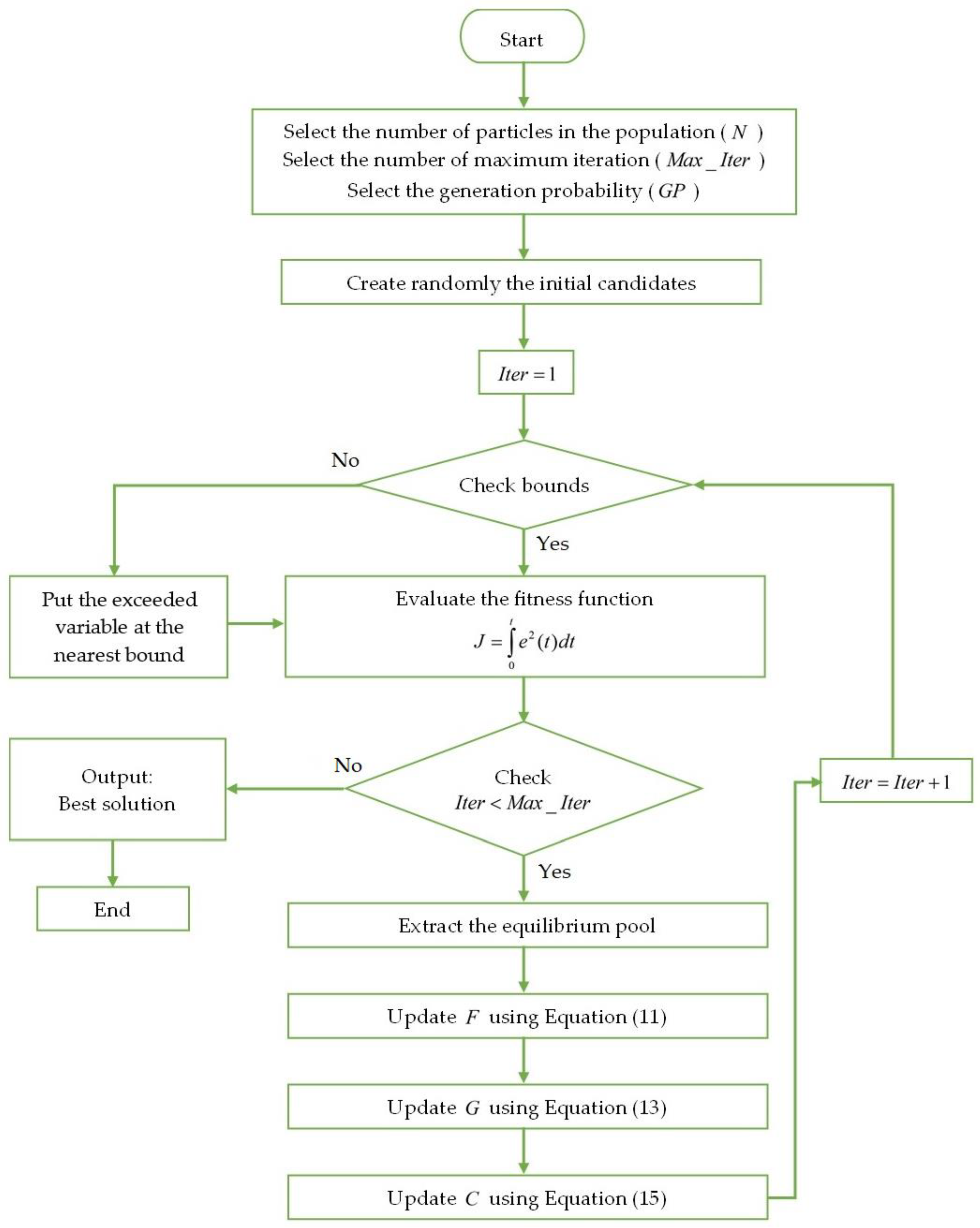
Figure 1. The flowchart of the Equilibrium Optimizer.
Fractalfract 07 00460 g001
Figure 2. Block diagram of the proposed direct integer-order approximation method.
Fractalfract 07 00460 g002
Figure 3. Unit step responses of Equations (31)–(36).
Fractalfract 07 00460 g003
Figure 4. Unit step responses of unstable transfer function for operator-based, GL, and proposed methods.
Fractalfract 07 00460 g004
Figure 5. Bode diagram of stable transfer function for the operator-based, Exact, and Proposed methods.
Fractalfract 07 00460 g005
Figure 6. Nyquist diagram of stable transfer function for the operator-based, Exact, and Proposed methods.
Fractalfract 07 00460 g006
Figure 7. Closed loop control system.
Fractalfract 07 00460 g007
Figure 8. Unit step responses and error plot of Tm(s) and T ( s ) .
Fractalfract 07 00460 g008
Figure 9. Comparison of unit step responses in Equations (45)–(52).
Fractalfract 07 00460 g009
Figure 10. Comparison of step responses of the integer-order approximate transfer functions.
Fractalfract 07 00460 g010
Figure 11. Closed loop control system with proportional controller.
Fractalfract 07 00460 g011
Figure 12. Comparison of closed-loop step responses for G p r o p o s e d ( s ) , G p a d e ( s ) and G ( s ) .
Fractalfract 07 00460 g012
Table 1. Errors based on time response for different methods and approximations of different orders.
MethodOrder of ApproximationMSE (10−5)
CFE222.5229
280.7592
340.2811
Oustaloup2213.9400
3411.5180
4811.6350
Matsuda223.5524
280.6710
340.0852
M-SBL2213.5050
280.4819
340.2716
Proposed40.3864
Table 2. Performance specifications for unit step responses of Equations (31)–(36).
MethodsRise Time
(s)
Settling Time (5%)
(s)
Peak Time
(s)
Peak ValueOvershoot (%)Steady State Error
GL Method4.410616.984510.52000.871124.44320
G P r o p o s e d ( s ) 4.427623.304310.60000.866723.81760
GCFE(s)4.400925.005010.53000.872024.57490.0048
GOus(s)4.382215.993210.08000.844420.62410.0110
G M a t ( s ) 4.309816.442710.04000.857522.49290.0008
G M S B L ( s ) 4.575017.269810.44000.819117.01910.0006
Table 3. Performance data of Bode and Nyquist diagrams.
MethodsOrder of ApproximationGain Margin (dB)Phase Margin (Degree)Critical Point
CFE814.53368.9600−0.1877
Oustaloup817.48958.3900−0.1337
Matsuda817.10051.9000−0.1398
M-SBL823.200None−0.0693
Proposed515.71399.4540−0.1641
Exact-14.406109.8400−0.1904
Table 4. Time response performance characteristics of Equations (45)–(52).
MethodsRise Time
(s)
Settling Time (5%)
(s)
Peak Time
(s)
Peak ValueOvershoot (%)Steady State Error
GL Method1.063021.96062.84001.565856.57640
GProposed (s)1.071924.09462.85001.579957.99230
G P S O ( s ) 0.995126.64592.84001.633263.32220.0258
GBlock_Pulse1(s)1.177731.88593.11001.528252.81800.0458
G B l o c k _ P u l s e 2 ( s ) 0.875621.19732.73001.635163.51470.0293
GBT(s)0.888332.33212.80001.794579.45130.0007
G S P A ( s ) 0.838829.66012.88001.666266.61860.0007
GHNA(s)0.867932.12062.84001.886588.64640.0007
Table 5. Time response performance characteristics of Equations (53)–(55).
MethodsRise Time
(s)
Settling Time (5%)
(s)
Peak Time
(s)
Peak ValueOvershoot (%)Steady State Error
GL Method1.278610.02162.78004.738618.46390
G P r o p o s e d ( s ) 1.23426.35912.75004.772319.30850
G p a d e 46 ( s ) 1.45457.12692.96004.453711.34150.07
Disclaimer/Publisher’s Note: The statements, opinions and data contained in all publications are solely those of the individual author(s) and contributor(s) and not of MDPI and/or the editor(s). MDPI and/or the editor(s) disclaim responsibility for any injury to people or property resulting from any ideas, methods, instructions or products referred to in the content.