Article

Fractional-Order Phase Lead Compensation Multirate Repetitive Control for Grid-Tied Inverters

1
Department of Electrical & Control Engineering, Cheongju University, Cheongju 28503, Republic of Korea
2
School of Mechanical and Electrical Engineering, Henan Industry and Trade Vocational College, Zhengzhou 451191, China
3
School of Electronic and Information, Zhongyuan University of Technology, Zhengzhou 451191, China
*
Author to whom correspondence should be addressed.
Fractal Fract. 2023, 7(12), 848; https://doi.org/10.3390/fractalfract7120848
Submission received: 2 November 2023 / Revised: 22 November 2023 / Accepted: 28 November 2023 / Published: 29 November 2023
(This article belongs to the Special Issue Applications of Fractional-Order Systems to Automatic Control)

Abstract

:
To reduce computational load and memory consumption, multirate repetitive control (MRC) with downsampling rates provides a flexible and efficient design for proportional-integral multi-resonant repetitive control (PIMR-RC) systems for grid-tied inverters. However, in MRC systems, repetitive controllers with low sampling rates produce low delay periods, and integer-order phase lead compensation may cause undercompensation or overcompensation. These imprecise linear phase lead compensations may result in deteriorated control performance. To address these problems, based on an infinite impulse response (IIR) filter, a fractional-order phase lead proportional-integral multi-resonant multirate repetitive control (FPL-PIMR-MRC) is proposed for grid-tied inverters in this paper. The proposed method can provide a suitable fractional phase lead step to achieve a wide stability region, minor tracking errors, and low hardware costs. The IIR fractional-order lead filter design, stability analysis, and the step-by-step parameter tuning of the FPL-PIMR-MRC system are derived in detail. Finally, simulation performed confirms the feasibility and effectiveness of the proposed scheme.

1. Introduction

With the development of renewable energy generation systems, pulse-width modulated (PWM) grid-tied inverters, serving as a crucial interface connecting distributed generation systems to the grid, have attracted widespread and increasing attention [1,2]. Nevertheless, owing to uncertainties in the parameters, nonlinear loads, and other factors, when the inverter works, it generates a lot of harmonics, resulting in poor control performance and high total harmonic distortion (THD) [3,4]. Repetitive control (RC) effectively achieves zero steady-state error tracking for any periodic signals and provides an excellent harmonic compensation capability for grid-tied inverters [5,6,7]. Owing to the inherent delay in RC, it has poor dynamic performance [8]. Therefore, other feedback controllers, including proportional-integral (PI) or proportional resonance (PR), are combined with RC to form a composite RC scheme [9,10]. The composite RC, consisting of RC and PI control, typically exists in two structural forms, either in series or in parallel, and is widely used in grid-tied inverter control systems. For instance, ref. [11] introduces a proportional-integral multi-resonant RC (PIMR-RC) scheme with outstanding harmonic suppression performance. This scheme incorporates an enhanced RC and a proportional gain in parallel.
Generally, to cut down the cost of power devices and improve the grid current quality, raising the grid-tied inverter’s switching frequency is an effective method [12]. Hence, the switching frequency of power devices can reach 10 kHz or even higher in grid-tied inverters. Furthermore, in a traditional single-rate RC (SRC) system, the sampling rate of the RC is generally the same as the switching frequency of the grid-tied inverter. A higher switching frequency implies an elevated sampling frequency. Nevertheless, as the sampling rate of the RC increases, so does the digital controller’s memory consumption and computational load [13], and the stability of the system will also deteriorate. Therefore, a multirate RC (MRC) scheme for PWM inverter control has been proposed [14]. In MRC systems, the RC controller works at a reduced sampling rate (RC rate), whereas the inverter system operates at a high sampling rate (feedback rate). Typically, the feedback rate is an integer multiple of the RC rate. Hence, as the RC loop has a reduced sampling rate, the computational load and the memory consumption will significantly reduce. A low sampling frequency will reduce the switching loss and cut down hardware costs effectively. Furthermore, previously proposed MRCs, normally with down-sampling schemes, have been successfully applied to active power filters (APF) [15], PWM inverters [16,17], motion control [18], and in other application fields.
However, in MRC systems, the low sampling rate will result in low delay periods N m , which leads to imprecise linear phase lead compensation. For instance, assuming the phase lead compensator is z m k , this introduces a phase lead angle θ = k × m × ( ω / ω N ) × 180 at ω , where k, ω , and ω N represent the phase lead step, the angular frequency, and the Nyquist frequency, respectively. m is termed the “sampling ratio” [19], which is equal to the ratio of the feedback rate to the RC rate. Obviously, as m increases, this can easily result in lower phase compensation resolution. Because larger m leads to a lower sampling rate of RC, this will decrease the phase compensation precision [20] or even make the system unstable. Thus, selecting a suitable phase lead step k is necessary to achieve better phase lead compensation, a wider stability region, and more minor tracking errors. Considering the above issues, a fractional-order phase lead RC is proposed, utilizing a finite impulse response fractional lead (FIR-FL) filter [21,22] or an infinite impulse response fractional lead (IIR-FL) filter [23]. Most proposed schemes can achieve better control performance using an FIR-FL filter or an IIR-FL filter approximating the item z m k with a fractional k. Furthermore, fractional-order phase lead compensation has also been successfully applied to MRC systems [24]. Nevertheless, most of these MRC schemes are based on plug-in RC systems and an FIR-FL filter, and there are no MRC schemes based on a PIMR-RC system and IIR-FL filter in the published literature. Furthermore, in practical applications, it is necessary to further research fractional-order MRCs to find a better universal MRC design [25]. There are also many studies on the application of fractional-order control (FOC) in inverters [26,27] and in some other fields [28,29], and many methods have also emerged for solving and analyzing fractional-order models [30,31,32].
In view of this, a fractional-order phase lead proportional-integral multi-resonant multirate repetitive control (FPL-PIMR-MRC) scheme is proposed for grid-tied inverters. The proposed scheme, characterized by a rapid error convergence rate and low THD, can attain precise fractional-order phase lead compensation, reduced computational load, and diminished memory consumption. The primary contributions of this work can be succinctly summarized as follows:
(1)
A PIMR-MRC controller is introduced to enhance control performance, offering reduced computational load and lower memory consumption for grid-tied inverters. It not only provides a wider stability region but also maintains excellent harmonic suppression performance.
(2)
Using an IIR-FL filter to approximate the fractional part of the phase lead step, precise compensation for the phase lag problem in the PIMR-MRC system is achieved.
(3)
The proposed FPL-PIMR-MRC scheme not only improves the system stability and the quality of the grid-injected current but also has a fast error convergence rate, because it can accommodate a larger RC gain. A comprehensive analysis of FPL-PIMR-MRC based on an IIR-FL filter, and an FIR-FL filter, respectively, is also provided.

2. Modeling the Single-Phase PWM Inverter

A model of the single-phase LCL-type grid-tied PWM inverter is illustrated in Figure 1 [33,34]. It mainly comprises an LCL filter, a single-phase full-bridge inverter, a current controller G i ( s ) , and a phase-locked loop (PLL). In the LCL filter, L 1 and L 2 are the inductors of the inverter side and the grid side, respectively, and C is the filter capacitor. i 1 and i c are the currents of the inductor L 1 and the capacitor C, respectively. R 1 and R 2 are the parasitic resistors of the LCL filter. R 1 and R 2 are the parasitic resistors of the LCL filter. R c is a passive damping resistor used to suppress the resonant peak of the LCL filter. u i n v is the output voltage of the inverter; it contains a large number of harmonics near the switching frequency, which can be filtered by LCL filters to reduce pollution to the grid. i g , I r e f , and u g are the grid current, the reference current amplitude, and the grid voltage, respectively. u P C C is the voltage at the point of common coupling (PCC) for the grid. E d c and ZOH are the DC bus voltage and a zero-order holder.
The inverter converts DC into AC, and the LCL low-pass filter is used to filter out higher-order harmonics in the system. The current controller plays a pivotal role in achieving high-performance control in the grid-tied inverter system, and it is also the primary focus of investigation in this paper. The PLL collects the grid voltage phase and provides the sampling frequency f for the current controller. The current error i e r r o r is produced by the grid feedback current i g to the reference current i r e f . The current error signal i e r r o r is fed into the current controller, and its output serves as the PWM inverter control signal. Then, a closed-loop current control system with grid current negative feedback is established.
Ignoring the parasitic resistors of the L 1 and L 2 , and assuming the state variable x = i 1 i g u c T , the system input u = u i n v u g T , and the system output y = i g . According to Kirchhoff’s theorem, the balance equations for LCL filters are:
u i n v u c = L 1 d i 1 d t + C d u c d t R c , u c u g = L 2 d i g d t C d u c d t R c , i 1 i g = C d u c d t .
By Laplace transformation on Equation (1), the equation in the s-domain can be obtained as follows:
I 1 ( s ) = U i n v ( s ) U c ( s ) R c C s U c ( s ) s L 1 , I g ( s ) = U c ( s ) U g ( s ) + R c C s U c ( s ) s L 2 , U c ( s ) = I 1 ( s ) I g ( s ) s C .
Accordin to Equations (1) and (2), the transfer function of the u i n v to i g can be derived as:
P ( s ) = R c C s + 1 L 1 L 2 C s 3 + ( L 1 + L 2 ) R c C s 2 + ( L 1 + L 2 ) s .
where P ( s ) is the controlled plant of the current controller in the s-domain.
Grid-tied inverters typically use high-frequency sinusoidal PWM (SPWM) modulation technology with a switching frequency exceeding 10 kHz. Consequently, the inverter module can be considered a unit with a gain of one. Therefore, a diagram of the grid current closed-loop control system can be represented as in Figure 2.
Substituting the parameter values (shown in Table 1) into the expression (3) and discretizing at the sampling frequency of 10 kHz with the ZOH discretization method, the controlled plant of the current controller in the z-domain can be derived as
P ( z ) = 0.005908 z 2 + 0.004191 z 0.002328 z 3 2.024 z 2 + 1.521 z 0.4976 .

3. Multirate Repetitive Control

3.1. Conventional Repetitive Control

Figure 3 illustrates the structural diagram of the conventional repetitive control (CRC).
From Figure 3, r ( z ) is the input signal, and y ( z ) is the output signal. The transfer function expression from the input to the output of CRC in the z-domain is expressed as
G c r c ( z ) = y ( z ) r ( z ) = k r Q ( z ) z N 1 Q ( z ) z N ,
where k r is the RC gain, which affects the amplitude of the RC output signal, and the value of k r reflects the magnitude of the control effect of RC in the system. The smaller the k r , the more conducive it is for system stability, but at the same time, it weakens the role of the repetitive controller. Q ( z ) is an internal mode filter or a constant less than 1 to ensure stable convergence of the system and improve system stability. Typically, selecting Q ( z ) as a zero-phase low-pass filter provides greater stability compared to selecting a constant. N is the number of samples in a period of the repetitive signal. The larger the N, the higher the error-tracking accuracy of RC [35].

3.2. Proportional-Integral Multi-Resonant Repetitive Control

Based on CRC, a PIMR-RC system with excellent dynamic response and a fast convergence rate is proposed and described in detail in [11]. Figure 4 shows the structural diagram of the PIMR-RC system.
From Figure 4, the proportional gain, k p , is employed to enhance the dynamic response of the system. S ( z ) is a compensator normally selected as a low-pass filter, which is employed to decay the high-frequency harmonics. i r e f ( z ) is the reference current, i g ( z ) is the output current, u g ( z ) is a disturbance signal, P ( z ) is the plant model, and E ( z ) is the tracking error. G r c ( z ) is the RC controller, and its discrete transfer function expression is expressed as
G r c ( z ) = Q ( z ) z N 1 Q ( z ) z N z k k r S ( z ) .

3.3. Proportional-Integral Multi-Resonant Multirate Repetitive Control

The MRC system with downsampling rates can reduce the computational load and memory consumption due to the reduced sampling frequency of the system. In the MRC system, the feedback rate of the inverter feedback control loop is assumed to be f s , the RC rate is f m , and the corresponding sampling periods are T s and T m , respectively. z N m is the period delay of the MRC system; N m is equivalent to the ratio of f m to the fundamental frequency f g . In practical applications, to simplify analysis and reduce losses, m is typically an integer. Therefore, only the downsampling rate MRC with m 1 is discussed in this paper. The two sampling rates in the MRC system can be summarized as
f s = m f m , T m = m T s , N m = f m / f g ,   z = e s T s , z m = e s T m = e s m T s = z m .
In the MRC system, for example, m = 2, the parameters of the inverter feedback control circuit are f s = 10 kHz, f g = 50 Hz, and the sampling period T s = 1 / f s = 0.0001 s. Then, in the repetitive controller, the RC rate f m = f s / m = 5000 Hz, and the corresponding sampling period T m = m T s = 0.0002 s. The number of samples per cycle N m = f m / f g = 100. z is the operator under the feedback rate, and z m is the operator under the RC rate.
Based on the PIMR-RC system, a proportional-integral multi-resonant type multirate repetitive control (PIMR-MRC) is designed. Figure 5 displays the structural diagram of the PIMR-MRC system.
Similar to the function expression (6) of G r c ( z ) in Figure 4, the expression of G m r c ( z m ) can be described as follows:
G m r c ( z m ) = Q ( z m ) z m N m 1 Q ( z m ) z m N m z m k k r S ( z m ) ,
where Q ( z m ) is an internal mode filter, k r is the MRC gain, N m is the number of samples in one period, z m k is the phase lead compensator, and S ( z m ) is a low-pass filter used to improve the system stability.
As shown in Figure 5, the proportional control k p and a multirate RC controller G m r c ( z m ) are connected in parallel to form a PIMR-MRC composite controller. i r e f is the input reference grid current signal, i g is the grid current feedback signal, P ( z ) is the controlled pant model, u g is the disturbance signal, and E ( z ) is the tracking error signal. The G m r c ( z m ) has a reduced sampling rate f m , while the other grid current feedback system has a high sampling rate f s . The G m r c ( z m ) works at a reduced sampling rate and can reduce the computational load and memory consumption. Accordingly, the PIMR-MRC scheme is an improved PIMR-RC.
F 1 ( z ) is the anti-spectral aliasing filter, which intercepts signals with frequency | ω | > π / T m . E ( z m ) is a down-sampled tracking error signal, and U r ( z m ) is the output of G m r c ( z m ) . Finally, after up-sampling by a ZOH, the U r ( z ) can be obtained by an anti-imaging filter F 2 ( z ) with a cut-off frequency less than π / T m .
To simplify analysis, the multirate system needs to be equivalent to a single-rate system. Figure 6 shows the equivalent single sampling rate control system structure for PIMR-MRC; the sampling rate of the whole system is the RC rate. Clearly, the CRC system is a special MRC when m = 1 .
According to Figure 6, P ( z m ) is the plant model at the RC rate. If the sampling frequency of the system f s = 10 kHz, m = 2, then f m = f s / 2 = 5 kHz. P ( z m ) , with a low sampling frequency f m in the z-domain, is derived as
P ( z m ) = 0.02205 z m 2 + 0.01975 z m 0.002614 z m 3 1.052 z m 2 + 0.3 z m 0.2476 .
z m k not only addresses the phase lag induced by P ( z m ) and S ( z m ) but also compensates for the phase lag introduced by F 1 ( z ) , F 2 ( z ) , and ZOH. When f s is 10 kHz and m = 1, 2, 3, 4, the corresponding RC rates f m are 10 kHz, 5 kHz, 10/3 kHz, and 2.5 kHz, respectively. The phase lead compensation θ provided by z m k at the angular frequency ω with different m is shown in Figure 7.
As shown in Figure 7, the phase lead compensation angle θ grows more and more rapidly as the value of the sampling ratio m increases. It can be inferred that the accuracy of the phase lead compensation decreases at a low sampling rate when m is too large. Thus, the item z m k with an integer k may result in overcompensation or undercompensation, leading to deterioration of the current quality and even system instability. Therefore, to compensate for the phase delay precisely and to fully utilize the advantages of the MRC, an FPL-PIMR-MRC scheme is proposed.

4. Fractional-Order Phase Lead Compensation Multirate Repetitive Control

4.1. Design of Fractional-Order Phase Lead Compensation Filter

Based on the Thiran method [36], the IIR filter requires less order, less computational complexity, faster speed, and lower CPU performance requirements compared to the FIR filter with the same performance. Especially for the IIR filter based on an all-pass structure, the amplitude-frequency characteristics are all 0 dB within the Nyquist frequency band range. Thus, during the filter design process, only the phase frequency characteristics of the filter need to be adjusted, reducing the difficulty of filter design significantly [37].
In the MRC system, when the value of the phase lead step k is a fraction, that is
k = k i + d
where k i , d are the integer and the fractional part of k, respectively, then,
z m k = z m k i z m d .
The fractional-order phase lead item can be derived by substituting a delay operator z 1 with a lead operator z [22]. If the fractional item z m d is approximated by an M-order all-pass IIR filter, the discrete domain expression is
z m d H ( z m ) = 1 + a 1 z m 1 + + a M 1 z m ( M 1 ) + a M z m M a M + a M 1 z m 1 + + a 1 z m ( M 1 ) + z m M .
The calculation formula for the coefficient a k of the filter is
a k = ( 1 ) k M k n = 0 M d M + n d M + k + n , k = 1 , 2 , , M ,
where M is the order of the all-pass filter. When M = 1, 2, 3, 4, and 5, the coefficients a k can be calculated according to the formulas in Table 2.
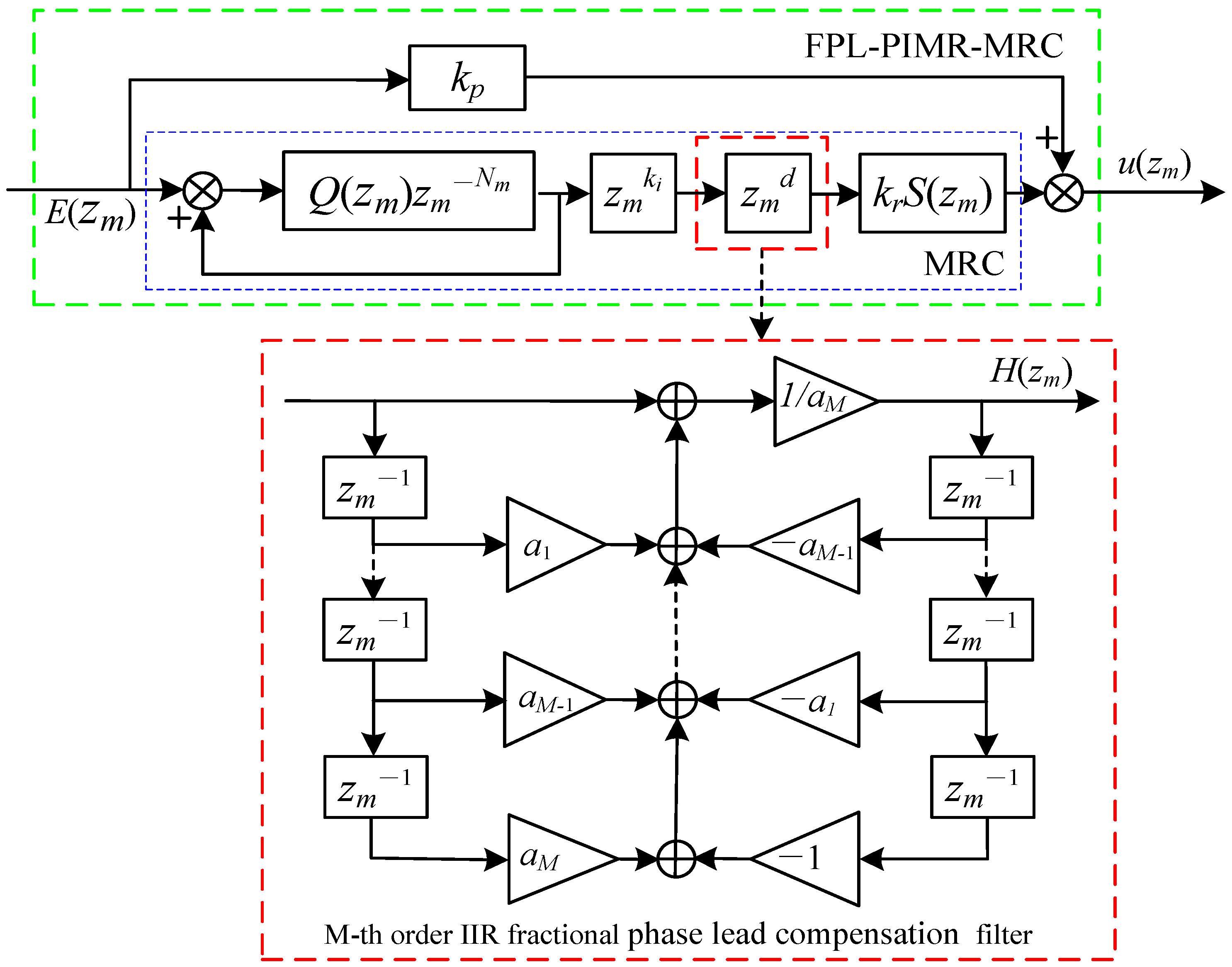
The structural diagram of FPL-PIMR-MRC is presented in Figure 8.
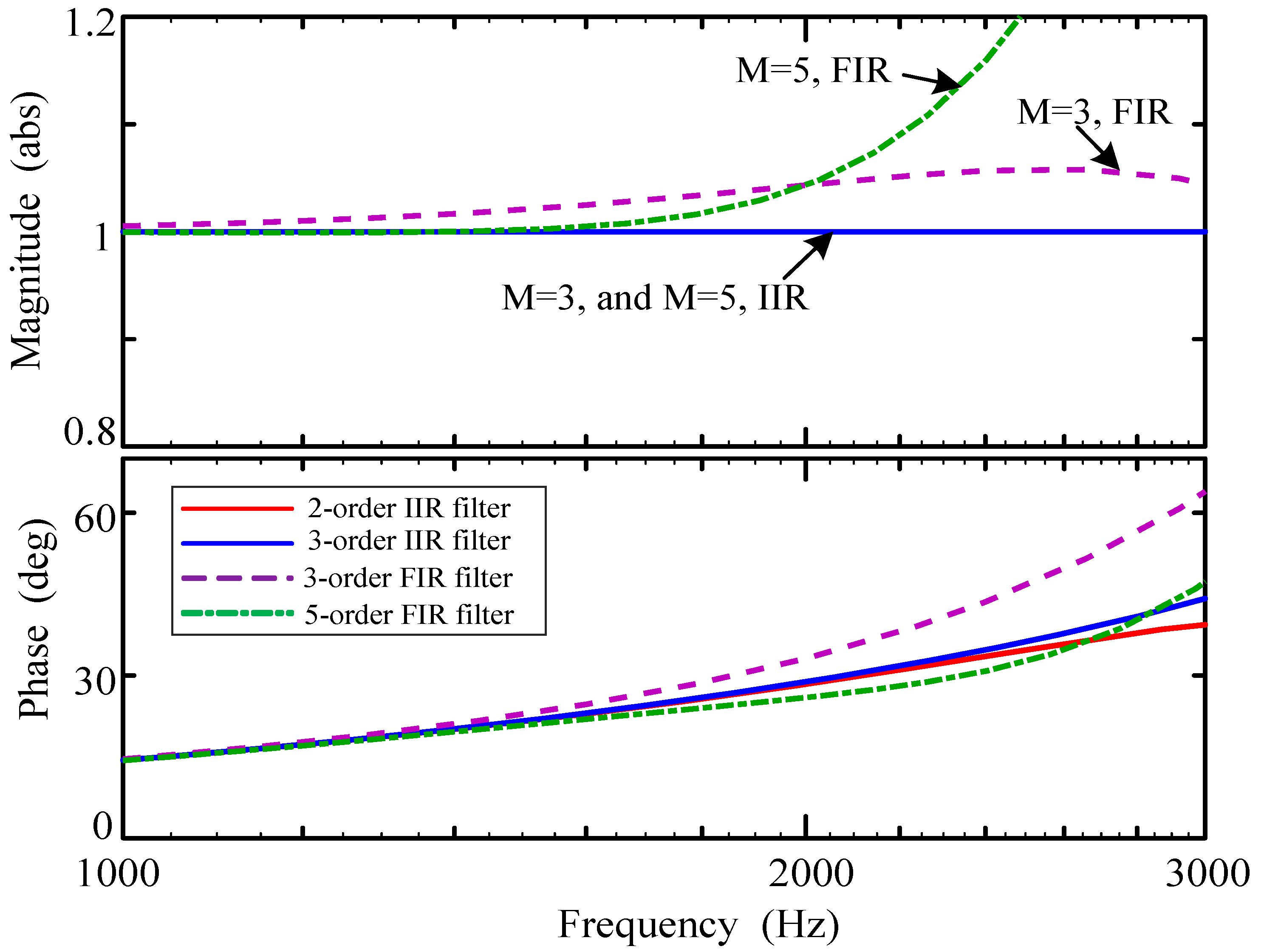
The ideal frequency characteristic of the fractional-order lead compensator is a unity magnitude response and a linear phase response. Assuming the fractional part d is 0.4, the IIR and the FIR fractional-order filters with different M-orders are used to approximate the fractional item z m d . The frequency characteristics of these filters are shown in Figure 9. The magnitude response of the IIR is one, while the FIR varies nonlinearly within the entire frequency bandwidth. Furthermore, both the IIR and FIR have excellent linear phase response within the range of 1 kHz. However, the IIR has a better linear phase response than FIR when the frequency exceeds 1 kHz. That is, the IIR has a wider linear phase region within the Nyquist bandwidth range. Moreover, the IIR filter can achieve fractional-order lead compensation with less computational complexity and lower order. However, achieving the same performance requires higher-order FIR filters, resulting in increased input-to-output delay and resource consumption [38]. Therefore, a 3rd-order IIR as the fractional-order phase lead compensator is employed in this paper.
According to (12), when M = 3, a 3rd-order IIR filter can be derived as
z m d 1 + a 1 z m 1 + a 2 z m 2 + a 3 z m 3 a 3 + a 2 z m 1 + a 1 z m 2 + z m 3 .
To meet the stability of Thrian all-pass filters, the optimal range of the fractional part d of the IIR filter is as follows [39]:
M 0.5 d M + 0.5 .
For instance, if k = 3.7 , M = 3 , and the sampling ratio m = 2 , according to (15), a value of d = 2.7 satisfies the stability criteria. Hence, using a 3rd-order IIR-FL filter, the fractional-order lead item z m 3.7 can be approximated as:
z m 3.7 = z m 1 z m 2.7 z m 1 z m 3 + 0.2432 z m 2 0.03623 z m + 0.003602 0.003602 z m 3 0.03623 z m 2 + 0.2432 z m + 1 .

4.2. Stability Analysis of Fractional-Order Phase Lead Proportional-Integral Multi-Resonant Multirate Repetitive Control

Referring to Figure 6, the tracking error E ( z m ) can be derived as
E ( z m ) = 1 1 + ( G m r c ( z m ) + k p ) P ( z m ) ( i r e f ( z m ) u g ( z m ) ) = 1 ( 1 + k p P ( z m ) ) ( 1 + G m r c ( z m ) P 0 ( z m ) ) ( i r e f ( z m ) u g ( z m ) ) ,
where P 0 ( z m ) represents a new equivalent controlled plant of MRC, with its expression given by:
P 0 ( z m ) = P ( z m ) 1 + k p P ( z m ) .
The FPL-PIMR-MRC system is subject to two stability conditions [11]: ① The roots of the equation 1 + k p P ( z m ) = 0 lie in a unit circle. ② 1 + G m r c ( z m ) P 0 ( z m ) 0 . By selecting a suitable k p , condition ① can be achieved easily. The condition ② can be met unless the following expression holds:
Q ( z m ) z m N m ( 1 z m k k r S ( z m ) P 0 ( z m ) ) < 1 , z m = e j ω T m , 0 < ω < π / T m .
i . e . , 1 z m k k r S ( z m ) P 0 ( z m ) < z m N m 1 Q ( z m ) 1 .
When the signal frequency matches the fundamental frequency or its integer multiple within the bandwidth, z m N m 1 approaches 1. Q ( z m ) is typically chosen as a zero-phase low-pass filter. Thus, Q ( z m ) also approaches 1. Therefore, condition ② can be derived as
1 z m k k r S ( z m ) P 0 ( z m ) ) < 1 .
Thus, the conditions for system stability are the same as for the PIMR-RC system. According to [11], the sufficient conditions for ② are as follows:
θ s ( ω ) + θ P 0 ( ω ) + k ω T m < 90 ,
0 < k r < min ω 2 cos ( θ s ( ω ) + θ P 0 ( ω ) + k ω T m ) N s ( ω ) N P 0 ( ω ) ,
where N s ( ω ) and θ s ( ω ) represent the magnitude and the phase characteristics of S ( z m ) , while N P 0 ( ω ) and θ P 0 ( ω ) represent the magnitude and the phase characteristics of P 0 ( z m ) , respectively. Furthermore, the phase lead step k and the MRC gain k r can be calculated using (22) and (23), respectively.

5. Parameters Design of Fractional-Order Phase Lead Proportional-Integral Multi-Resonant Multirate Repetitive Control

Referring to Figure 8, five parameters need to be designed for the FPL-PIMR-MRC. They are k p , Q ( z m ) , S ( z m ) , k r , and z m k , respectively.

5.1. Proportional Gain k p

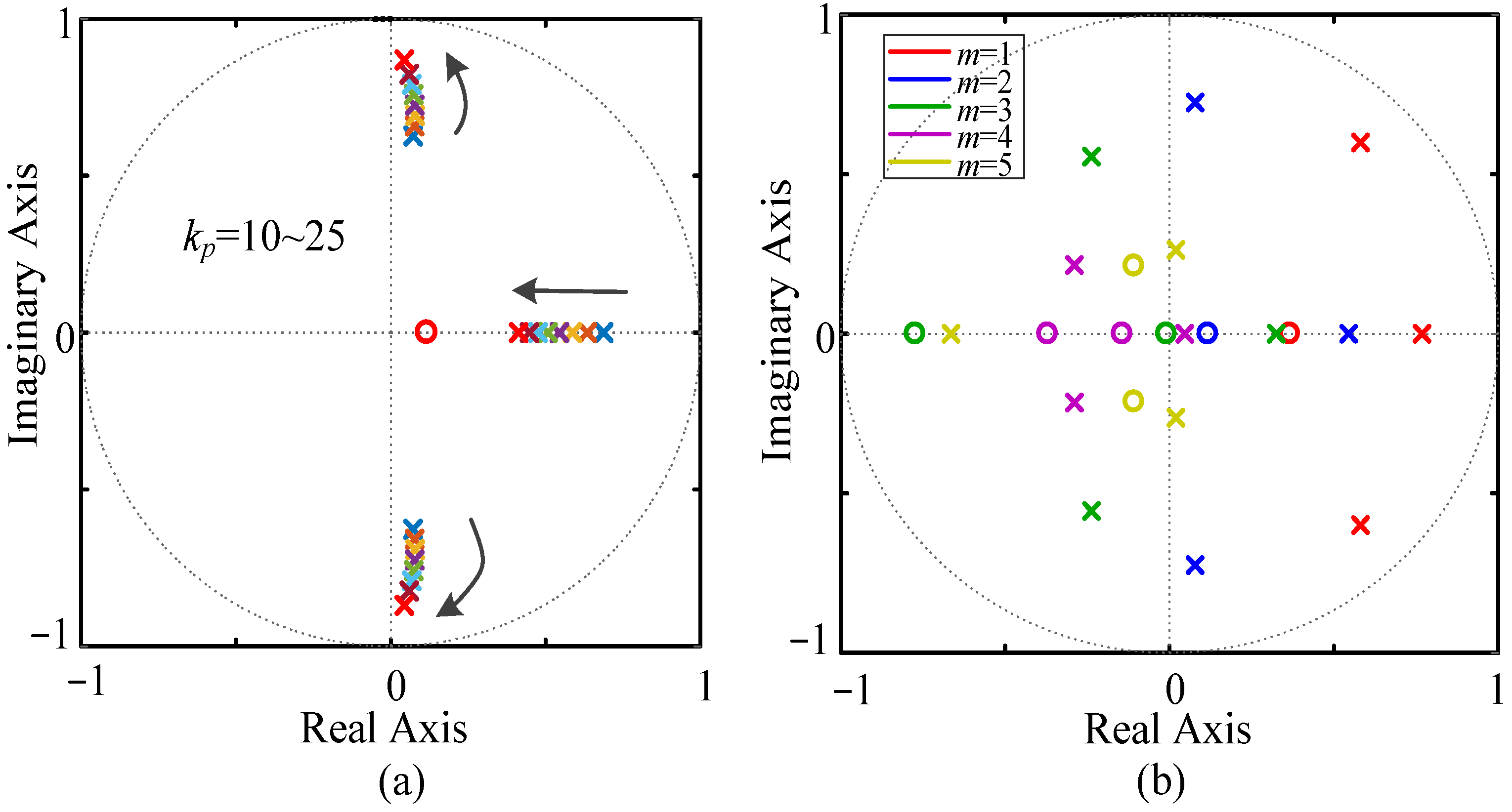
Selecting an appropriate k p is crucial to expanding the stability region and enhancing the error tracking accuracy [40]. According to condition ①, all the roots of equation 1 + k p P ( z m ) = 0 should be located within a unit circle at low sampling rates. In Figure 10a, when the value of k p is varied from 10 to 25, condition ① is satisfied. Figure 10b shows all roots of the equation 1 + k p P ( z m ) = 0 lie in a unit circle at different sampling rates when k p = 16. Therefore, to strike a balance between system stability and accuracy of error tracking, the value of k p has been chosen as 16.

5.2. Internal Mode Filter Q ( z m )

To avoid phase delay caused by the filters, Q ( z m ) can be selected as a zero-phase low-pass filter to improve the system stability.
Q ( z m ) = 0.25 z m 1 + 0.5 + 0.25 z m .

5.3. Low-Pass Filter S ( z m )

To effectively suppress high-frequency signals, S ( z m ) is set to be a fourth-order Butterworth low-pass filter. At the low sampling rate for different m values (m = 1, 2, 4), and setting the cut-off frequency to be 1000 Hz, S ( z m ) can be calculated as follows:
S ( z m ) = 0.004824 z m 4 + 0.0193 z m 3 + 0.02895 z m 2 + 0.0193 z m + 0.004824 z m 4 2.37 z m 3 + 2.314 z m 2 1.055 z m + 0.1874 , m = 1 , 0.04658 z m 4 + 0.1863 z m 3 + 0.2795 z m 2 + 0.1863 z m + 0.04658 z m 4 0.7821 z m 3 + 0.68 z m 2 0.1827 z m + 0.03012 , m = 2 , 0.04328 z m 4 + 1.731 z m 3 + 2.597 z m 2 + 1.731 z m + 0.4328 z m 4 + 2.37 z m 3 + 2.314 z m 2 + 1.055 z m + 0.1874 , m = 4 .
However, the phase lag may be more severe after adding a low-pass filter S ( z m ) . Phase lag will affect the dynamic response of the system. Thus, a phase lead compensator needs to be introduced.

5.4. RC Gain k r and Phase Lead Compensator z m k

Following expression (23), if the angle ( θ s ( ω ) + θ P 0 ( ω ) + k ω T m ) approaches zero degrees, by selecting an appropriate k, a larger k r can be obtained. Thereby, the error convergence rate and system stability can be improved significantly. When m = 2, the phase-frequency characteristics of S ( z m ) P 0 ( z m ) z m k with different k are shown in Figure 11.
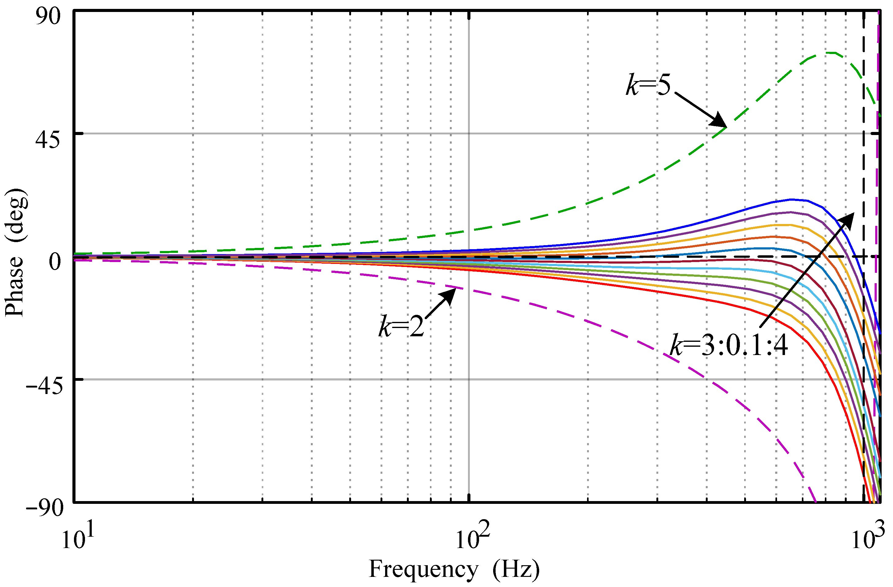
From Figure 11, within the frequency range of 1 kHz, the phase-frequency characteristics of S ( z m ) P 0 ( z m ) z m k approach zero degrees when the phase lead step k varies from 3 to 4. Furthermore, the variation range of phase-frequency characteristics is within ±90°, which meets the system stability requirements. However, when k = 2 or k = 5, the ( θ s ( ω ) + θ P 0 ( ω ) + k ω T m ) values deviate from zero degrees significantly or potentially surpass the stable range.
To ascertain the optimal value of phase lead compensation, an IIR fractional-order filter utilizing the Thiran method was employed. When k changes every 0.1 intervals from 3 to 4, the fractional part of the k can be approximated using a 3rd-order IIR-FL filter. Obviously, when k = 3.7, the phase-frequency characteristics can meet the stability requirements and approach zero degrees within 1 kHz.
According to (21), define
H ( e j ω T m ) = 1 k r e j ω k T m S ( e j ω T m ) P 0 ( e j ω T m ) .
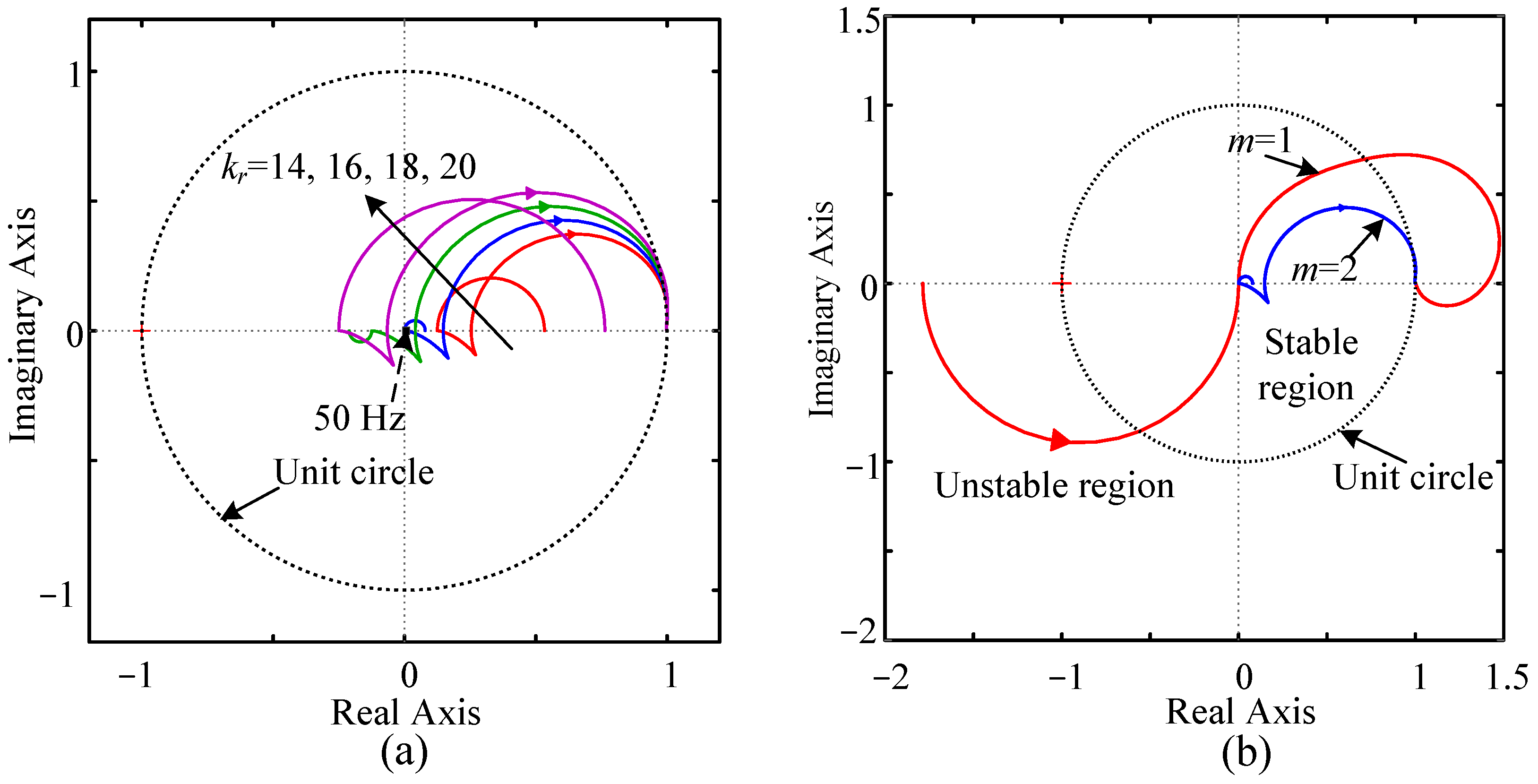
To guarantee system stability, the trajectories of H ( e j ω T m ) should be inside a unit circle. The closer H ( e j ω T m ) is to the unit circle’s center, the faster the error convergence of the system [7]. When k = 3.7, and considering system modeling errors, the range of values for k r is determined as k r [ 0 22 ] .
Figure 12a shows the Nyquist curves H ( e j ω T m ) ( ω [ 0 , π / T m ] ) within the unit circle when the RC gain k r varies from 14 to 20. Note that the frequency at the center of the circle is 50 Hz with k r = 16. Therefore, the Nyquist curve H ( e j ω T m ) with k r = 16 provides a wider stability margin at low frequencies. Figure 12b shows that when m = 1, the Nyquist curve H ( e j ω T m ) exceeds the system stable range. When m = 1, the RC rate equals the feedback rate, and both have a high sampling frequency. However, when m = 2, the RC rate is reduced by half, and the low sampling rate repetitive controller can reduce computational delays caused by itself in each control cycle. Therefore, it can be concluded that the stability margins of the MRC system have increased compared to the SRC system. Note that a larger m will produce imprecise phase compensation, which results in reduced system stability or even makes the system unstable.
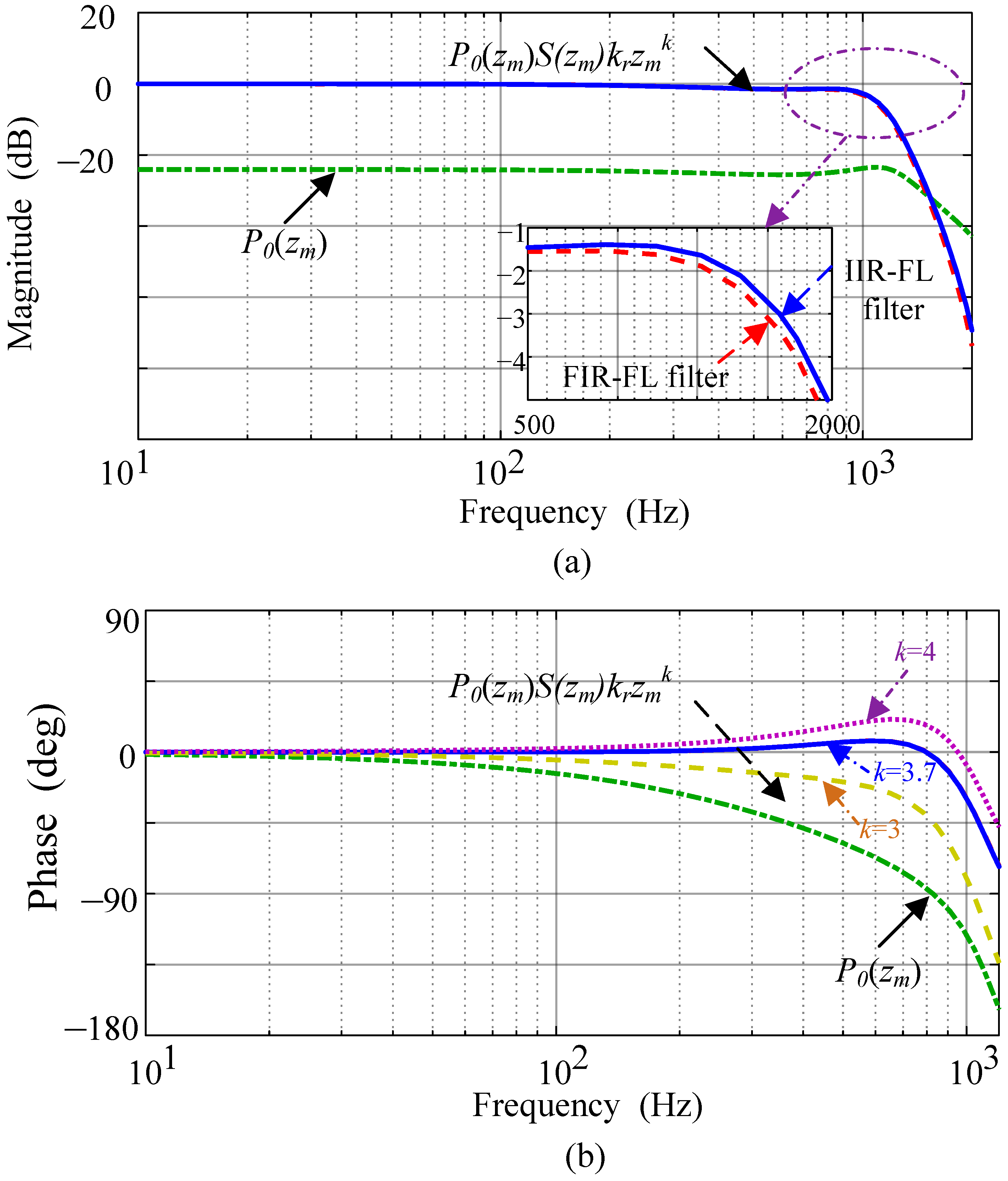
In practice, the ideal frequency characteristics of the compensated controlled object are unity gain and zero phase. Figure 13 shows the bode diagrams of P 0 ( z m ) and S ( z m ) P 0 ( z m ) k r z m k when m = 2. Figure 13a indicates that after compensation, the amplitude characteristic of S ( z m ) P 0 ( z m ) k r z m k with k r = 16 and k = 3.7 is closer to unity gain compared to P 0 ( z m ) . Furthermore, the gain of S ( z m ) P 0 ( z m ) k r z m k using an IIR-FL filter exceeds that of an FIR-FL filter between 500 Hz and 2000 Hz. A larger gain means smaller tracking errors and lower THD of the system. As shown in Figure 13b, the phase characteristic of S ( z m ) P 0 ( z m ) k r z m k with k r = 16 and k = 3.7 is closer to the zero-phase line than that with k = 3 or k = 4.
According to Figure 6, the open-loop system transfer function of FPL-PIMR-MRC is
G ( z m ) = G m r c ( z m ) P 0 ( z m ) .
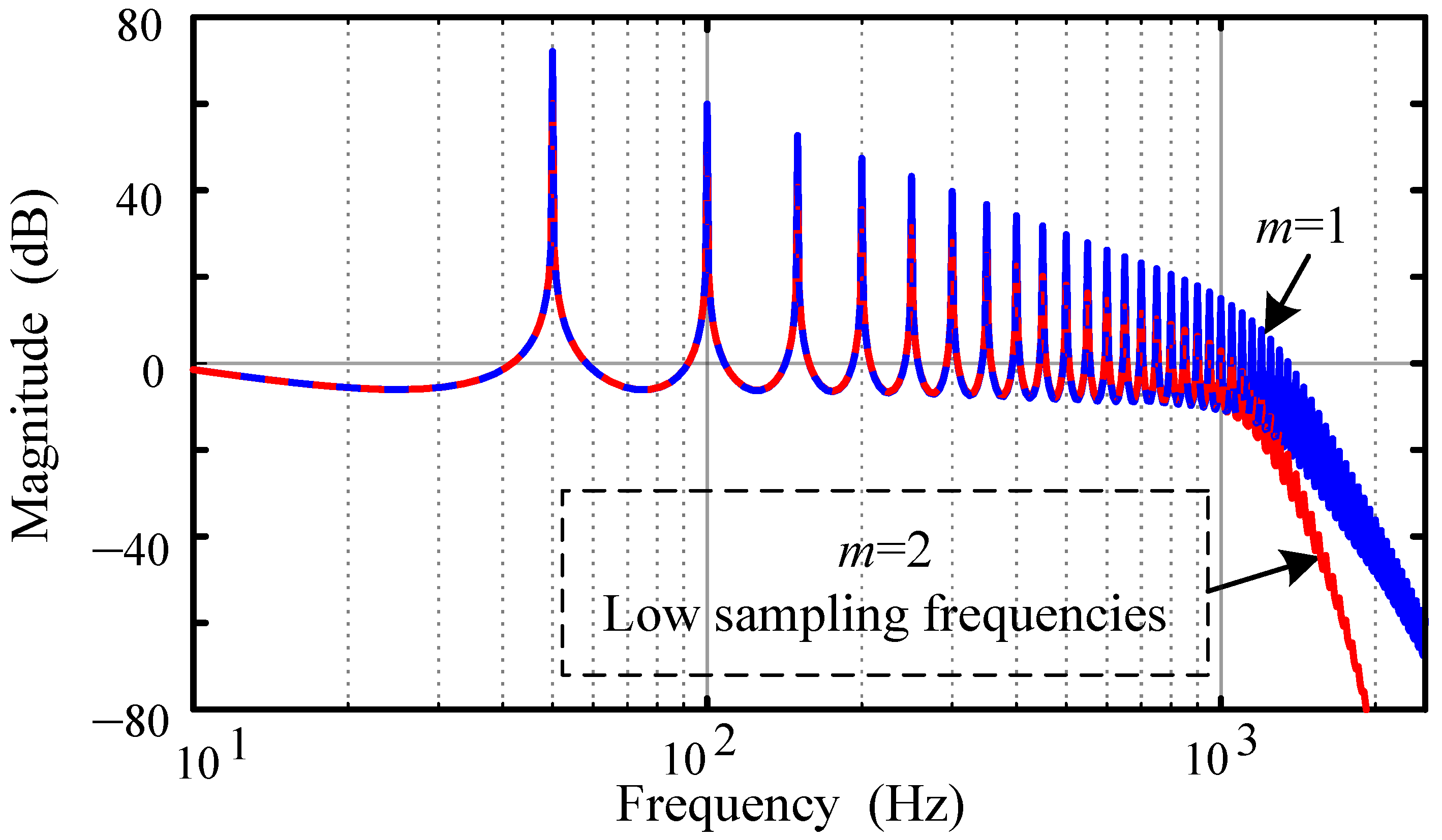
The open-loop system transfer function amplitude-frequency characteristic of FPL-PIMR-MRC with different sampling rates is shown in Figure 14.
Figure 14 shows that the system is an SRC system with a high sampling rate when m = 1. The SRC system trades excellent control performance at the cost of huge computation and memory usage. When m = 2, the sampling frequency of the RC controller decreases by half, and diminished computational burden and memory usage will be achieved.
Remark 1.
The FPL-PIMR-MRC system has a large open loop gain at low frequencies and rapid attenuation at high frequencies. Thus, the FPL-PIMR-MRC system can achieve a wider stability region compared to the SRC system. It is crucial to observe that reducing the sampling rate too much may result in poor harmonic suppression or even lead to system instability.

6. Simulation

As depicted in Figure 1, a model was constructed for the 2.2 kW LCL-type single-phase grid-tied inverter system. The schemes of PIMR-RC, PIMR-MRC, and FPL-PIMR-MRC for grid-tied inverters were employed, respectively. Then, simulation models for these three control schemes were established using the MATLAB/Simulink environment. The rated value of the i r e f is 10 A, and the other parameters are assumed to be configured according to Table 1. Additionally, according to [41], the filters of F 1 and F 2 are selected as follows:
F 1 = F 2 = 0.15 z 1 + 0.7 + 0.15 z .

6.1. Steady-State Response

Figure 15, Figure 16, Figure 17, Figure 18, Figure 19, Figure 20 and Figure 21 illustrate the steady-state response performance with different sampling rates. Figure 15 and Figure 16 show the single sampling rate control system; the others are the multirate control systems. The THD of the grid current i g is 3.14% just by proportional control, as shown in Figure 15. However, when the PIMR-RC system with k = 9 and k r = 16 is employed, the THD of i g decreases to 0.73%, as shown in Figure 16. It can be inferred that the CRC system can achieve excellent harmonic suppression performance with the single sampling rate control. Figure 17 illustrates the steady-state response of the PIMR-MRC system when m = 2, k = 4, and k r = 16. The THD value is 0.95% because the sampling rate is reduced by half, which leads to the output current being distorted.
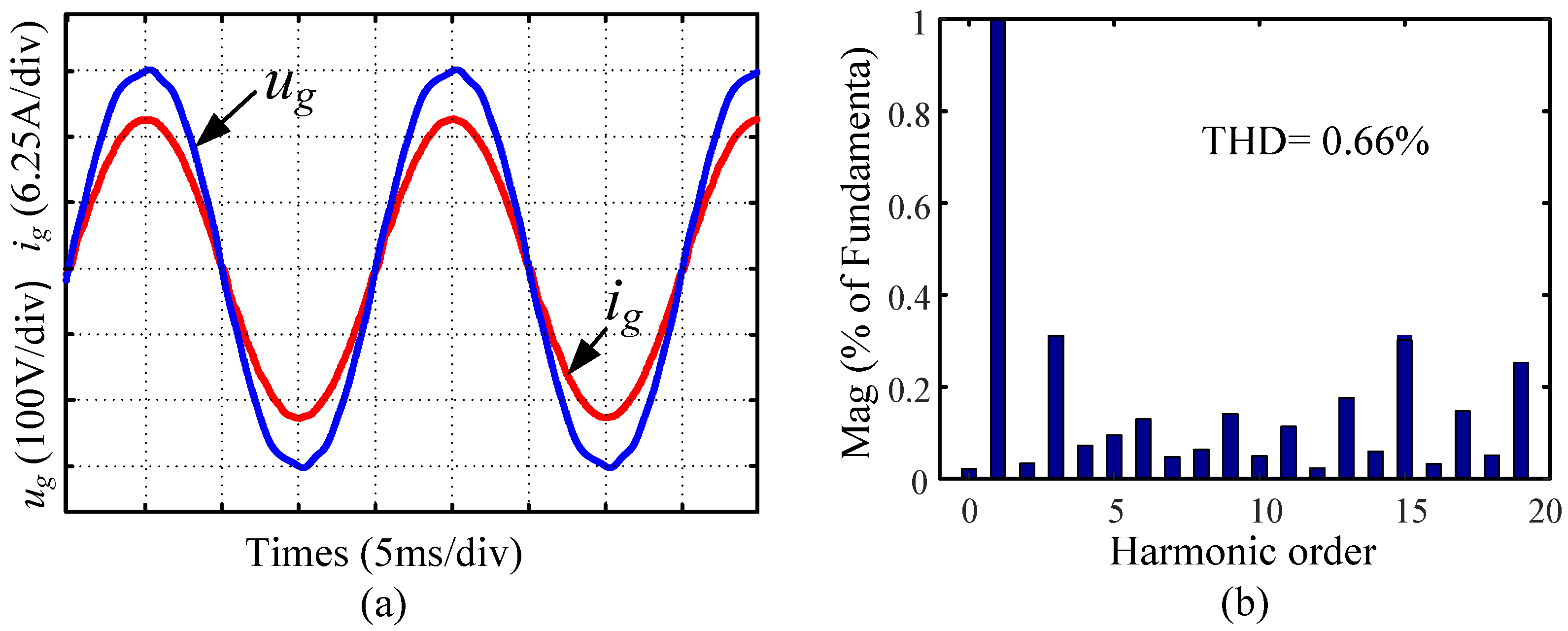
Figure 18 and Figure 19 show that the THD values of the FPL-PIMR-MRC system based on a 3rd-order FIR-FL filter or a 3rd-order IIR-FL filter with m = 2, k = 3.7, and k r = 16 are 0.66% and 0.51%, respectively. Obviously, due to the introduction of fractional-order phase lead compensation, the waveform quality of the grid current is improved. Additionally, because the IIR-FL filter exhibits a higher magnitude gain than the FIR-FL filter in the 500 Hz–2000 Hz range, it enhances the harmonic suppression performance for FPL-PIMR-MRC with the IIR-FL filter.
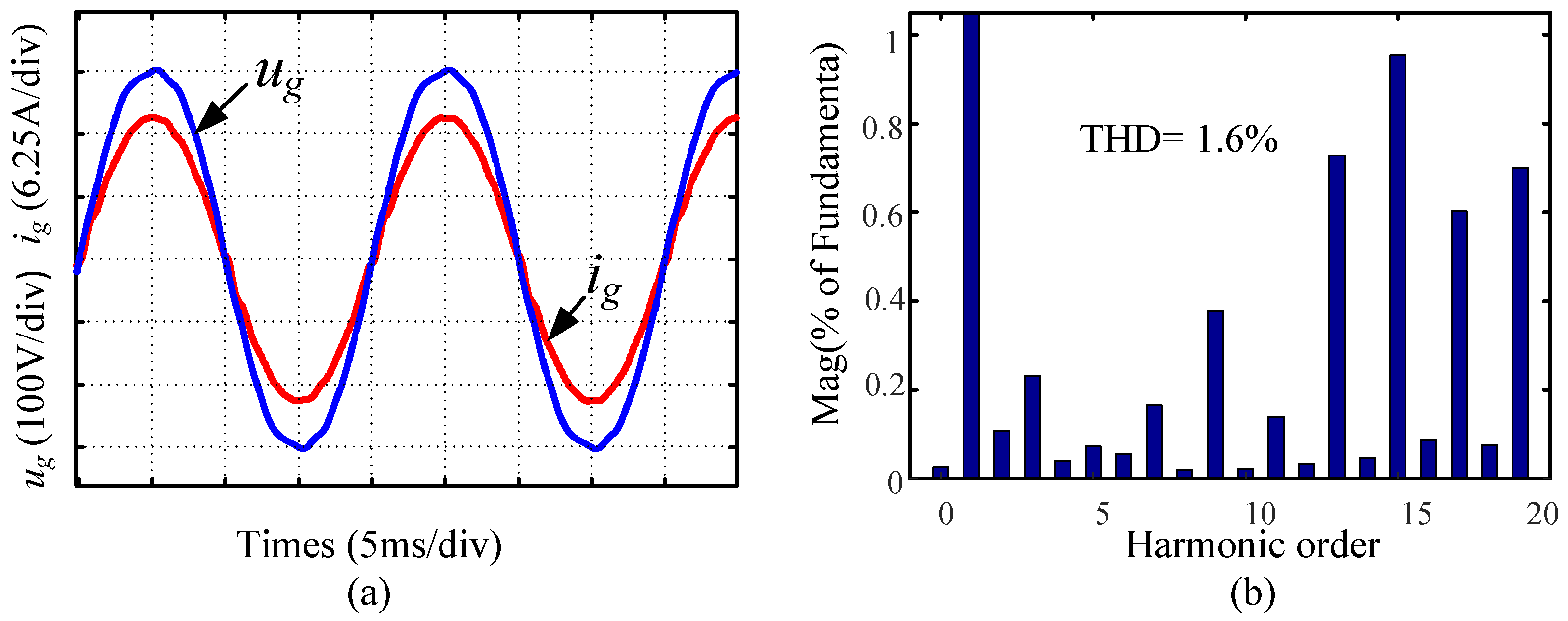
However, when the sampling rate of the RC controller is further reduced in the FPL-PIMR-MRC system, such as in Figure 20 and Figure 21, the sampling rate is decreased to one quarter of its original when m = 4. The THD values of the i g using the two fractional-order filters are increased to 1.6% and 1.32%, respectively. It is worth noting that as the m increases, the high-order harmonics increase significantly due to the open-loop gain decrease at high frequencies.

6.2. Transient Response

Figure 22 illustrates the tracking error of the PIMR-MRC system at different sampling rates. i g , i e r r o r , and i r e f represent the output current of the grid, the current error, and the reference current, respectively. When the rated value of the i r e f is adjusted from 5 A to 10 A, it is observed that, whether it is an SRC system (m = 1) or an MRC system (m = 2), the convergence time of the i r e f remains consistent at approximately 62 ms.
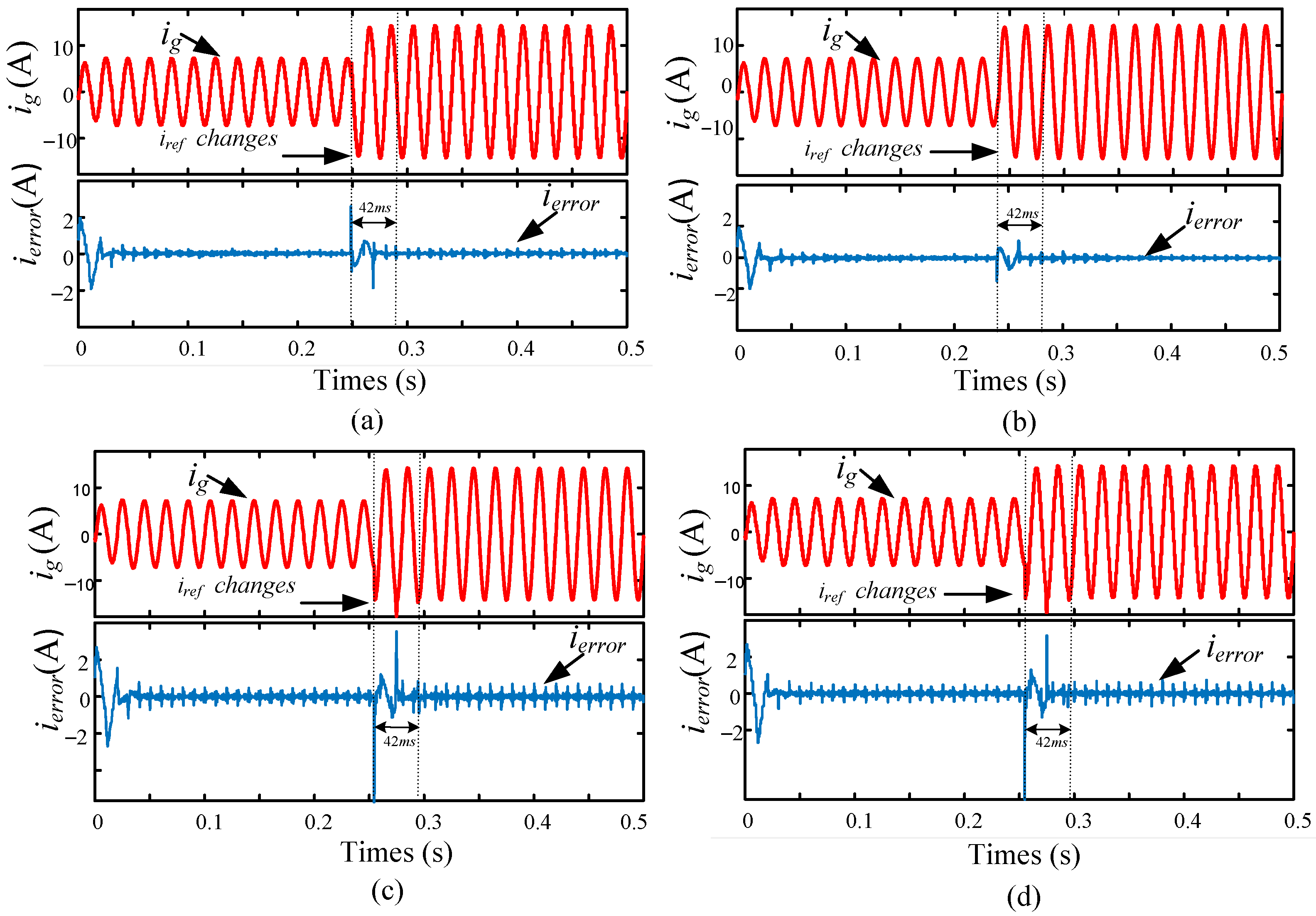
Figure 23 illustrates the tracking error of the FPL-PIMR-MRC system at different sampling rates. When the rated value of the i r e f is changed from 5 A to 10 A, the convergence time of the FPL-PIMR-MRC system, whether utilizing the IIR-FL filter or the FIR-FL filter, is approximately 42 ms, which is faster than for the PIMR-MRC system. The main reason is that the value of the RC gain k r has increased from 16 to 18, which improves the error convergence rate. Accordingly, fractional-order phase lead compensation can extend the RC gain, thereby improving the control performance of the system.
From Figure 22 and Figure 23, a larger i e r r o r is produced if the sampling rates increase. Furthermore, the higher the value of m, the greater the peak value of i e r r o r . For instance, the peak value of i e r r o r is approximately ±0.2 A when m = 1. Nevertheless, when m increases to 2, the peak value of i e r r o r is enlarged to approximately ±0.4 A, or even more to about ±0.7 A when m = 4, as shown in Figure 23c. In addition, for the proposed FPL-PIMR-MRC system with fractional-order phase (k = 3.7) lead compensation, such as in Figure 23b, the peak value of the error is ±0.3 A, which is smaller than that for the PIMR-MRC system without fractional-order compensation. Furthermore, as the IIR-FL filter exhibits a larger magnitude gain in some frequency ranges, the proposed FPL-PIMR-MRC system utilizing the IIR-FL filter has a smaller tracking error compared to systems employing the IIR-FL filter with identical parameters and sampling rates.
Remark 2.
Based on the Simulink experiments of the steady-state and transient response, it can be proved that when the fractional-order phase lead compensation is introduced, the proposed FPL-PIMR-MRC scheme can provide an accurate fractional phase lead step and a high gain, enlarging the stability margin of the system, and can then achieve better control performance in improving the quality of the grid-injected current.

7. Conclusions

This article introduces a fractional-order FPL-PIMR-MRC scheme utilizing an IIR-FL filter to achieve fractional-order compensation for grid-tied inverters. This design is both flexible and efficient, and is characterized by diminished computation and lower memory loss due to the RC loop having a reduced sampling rate. The sampling frequency f m and the down-sampling ratio m can be selected flexibly in practical applications. Therefore, it represents a universal design method for single-rate or multirate control systems. Furthermore, the proposed approach can achieve precise linear phase lead compensation by using a 3rd-order IIR-FL filter to approximate the fractional phase lead step k. The simulation results demonstrate the effectiveness of the proposed FPL-PIMR-MRC, which not only reduces hardware consumption but also has a wide stability region, low THD, and small tracking errors by selecting a suitable down-sampling ratio.
Additionally, the introduction of the fractional-order system based on an IIR-FL filter provides a more accurate phase lead compensation step for grid-tied inverters, improving the compensation accuracy so as to improve the control performance of the system. Moreover, due to the advantages of high control accuracy and excellent stability of fractional-order control systems, their application value has been highlighted in some fields requiring high control accuracy and performance. The proposed approach can also be promoted for application in APF or other power conversion units.

Author Contributions

Conceptualization, F.L., H.-J.L. and H.Z.; methodology, F.L. and H.-J.L.; software, F.L.; validation, F.L.; formal analysis, F.L. and H.-J.L.; writing—original draft preparation, F.L.; writing—review and editing, F.L. and H.Z.; supervision, H.-J.L.; project administration, H.-J.L.; funding acquisition, H.-J.L. All authors have read and agreed to the published version of the manuscript.

Funding

This work was supported in part by the National Research Foundation of Korea, funded by the Korean government (MSIT) (NRF-RS-2022-00143178); in part by the Basic Science Research Program through the National Research Foundation of Korea, funded by the Ministry of Education (NRF-2020R1I1A3069569); in part by the Incubation Program for Young Master Supervisors under the grant of China (No. D202213); in part by the Foundation for University Youth Key Teachers by Henan province of China (No. 2018GGJS-213); and in part by the Graduate Student Research Innovation Program of Zhongyuan University of Technology under the grant of China (No. YKY2023ZK24).

Data Availability Statement

The authors confirm that the data supporting the findings of this study are available within the article.

Conflicts of Interest

The authors declare no conflict of interest.

Abbreviations

The following abbreviations are used in this manuscript:
MRCMultirate repetitive control
PIMR-RCProportional–integral multi-resonant repetitive control
PIMR-MRCProportional–integral multi-resonant multirate repetitive control
IIRInfinite impulse response
FPL-PIMR-MRCFractional-order phase lead proportional–integral multi-resonant multirate repetitive control
PWMPulse-width modulated
THDTotal harmonic distortion
FOCFractional-order control
RCRepetitive control
PIProportional integral
PRProportional resonant
SRCSingle-rate repetitive control
CRCConventional repetitive control
APFActive power filters
FIR-FLFinite impulse response fractional-order lead
IIR-FLInfinite impulse response fractional-order lead
PLLPhase-locked loop
PCCPoint of common coupling

References

  1. Chen, D.; Zhang, J.; Qian, Z. An Improved Repetitive Control Scheme for Grid-Connected Inverter with Frequency-Adaptive Capability. IEEE Trans. Power Electron. 2013, 60, 814–823. [Google Scholar] [CrossRef]
  2. Prasad, B.S.; Jain, S.; Agarwal, V. Universal Single-Stage Grid-Connected Inverter. IEEE Trans. Energy Convers. 2008, 23, 128–137. [Google Scholar] [CrossRef]
  3. Wu, Y.; Ye, Y. Internal Model-Based Disturbance Observer with Application to CVCF PWM Inverter. IEEE Trans. Ind. Electron. 2018, 65, 5743–5753. [Google Scholar] [CrossRef]
  4. di Benedetto, M.; Faro, A.; Bigarelli, L.; Lidozzi, A.; Solero, L. Constant Delay-Line Frequency Adaptive Repetitive-Resonant Control for Grid-Tied and Intentional Islanding Operations. IEEE Trans. Ind. Appl. 2023, 59, 1944–1955. [Google Scholar] [CrossRef]
  5. Zhou, K.; Wang, D. Digital Repetitive Learning Controller for Three-Phase CVCF PWM Inverter. IEEE Trans. Ind. Electron. 2001, 48, 820–830. [Google Scholar] [CrossRef]
  6. Ye, J.; Liu, L.; Xu, J.; Shen, A. Frequency Adaptive Proportional-Repetitive Control for Grid-Connected Inverters. IEEE Trans. Ind. Electron. 2021, 68, 7965–7974. [Google Scholar] [CrossRef]
  7. Zou, Z.; Zhou, K.; Wang, Z.; Cheng, M. Frequency-Adaptive Fractional-Order Repetitive Control of Shunt Active Power Filters. IEEE Trans. Ind. Electron. 2015, 62, 1659–1668. [Google Scholar] [CrossRef]
  8. Xu, F.; Zhu, M.; Ye, Y. The Stability of LCL-Type Grid-Tied Inverter Based on Repetitive Control and Grid Voltage Feed-Forward. IEEE J. Emerg. Sel. Top. Power Electron. 2023, 11, 1496–1506. [Google Scholar] [CrossRef]
  9. Zhang, K.; Kang, Y.; Xiong, J.; Chen, J. Direct Repetitive Control of SPWM Inverter for UPS Purpose. IEEE Trans. Power Electron. 2003, 18, 784–792. [Google Scholar] [CrossRef]
  10. Yang, Y.; Zhou, K.; Blaabjerg, F. Enhancing the Frequency Adaptability of Periodic Current Controllers with a Fixed Sampling Rate for Grid-Connected Power Converters. IEEE Trans. Power Electron. 2016, 31, 7273–7285. [Google Scholar] [CrossRef]
  11. Zhao, Q.; Ye, Y. A PIMR-Type Repetitive Control for a Grid-Tied Inverter: Structure, Analysis, and Design. IEEE Trans. Power Electron. 2018, 33, 2730–2739. [Google Scholar] [CrossRef]
  12. Wu, W.; He, Y.; Blaabjerg, F. An LLCL Power Filter for Single-Phase Grid-Tied Inverter. IEEE Trans. Power Electron. 2012, 27, 782–789. [Google Scholar] [CrossRef]
  13. Zundert, J.; Oomen, T.; Verhaegh, J.; Aangenent, W.; Antunes, D.J.; Heemels, W.P.M.H. Beyond Performance/Cost Tradeoffs in Motion Control: A Multirate Feedforward Design with Application to a Dual-Stage Wafer System. IEEE Trans. Control Syst. Technol. 2020, 28, 448–461. [Google Scholar] [CrossRef]
  14. Fujimoto, H.; Kawakami, F.; Kondo, S. Multirate Repetitive Control and Applications. In Proceedings of the American Control Conference, Denver, CO, USA, 4–6 June 2003; pp. 2875–2880. [Google Scholar]
  15. Xie, C.; Zhao, X.; Savaghebi, M.; Meng, L.; Guerrero, J.M.; Vasquez, J.C. Multirate Fractional-Order Repetitive Control of Shunt Active Power Filter Suitable for Microgrid Applications. IEEE J. Emerg. Sel. Top. Power Electron. 2017, 5, 809–819. [Google Scholar] [CrossRef]
  16. Zhang, B.; Zhou, K.; Wang, D. Multirate Repetitive Control for PWM DC/AC Converters. IEEE Trans. Ind. Electron. 2014, 61, 2883–2890. [Google Scholar] [CrossRef]
  17. Zeng, C.; Li, S.; Wang, H.; Miao, H. A Fractional Phase Compensation Scheme of PRMRC for LCL Inverter Connected to Weak Grid. IEEE Access 2021, 9, 167027–167038. [Google Scholar] [CrossRef]
  18. Ohnishi, W.; Strijbosch, N.; Oomen, T. Multirate State Tracking for Improving Inters ample Behavior in Iterative Learning Control. In Proceedings of the IEEE International Conference on Mechatronics (ICM), Kashiwa, Japan, 7–9 March 2021; pp. 1–6. [Google Scholar]
  19. Sadegh, N.; Hu, A.; James, C. Synthesis, Stability Analysis, and Experimental Implementation of a Multirate Repetitive Learning Controller. J. Dyn. Syst. Meas. Control 2002, 124, 668–674. [Google Scholar] [CrossRef]
  20. Chen, S.; Zhao, Q.; Ye, Y.; Qu, B. Using IIR Filter in Fractional Order Phase Lead Compensation PIMR-RC for Grid-Tied Inverters. IEEE Trans. Ind. Electron. 2023, 70, 9399–9409. [Google Scholar] [CrossRef]
  21. Zhao, Q.; Ye, Y. Fractional Phase Lead Compensation RC for an Inverter: Analysis, Design, and Verification. IEEE Trans. Ind. Electron. 2017, 64, 3127–3136. [Google Scholar] [CrossRef]
  22. Han, B.; Lai, J.; Kim, M. Down-Sampled Repetitive Controller for Grid-Connected Ćuk CCM Inverter. IEEE Trans. Emerg. Sel. Top. Power Electron. 2022, 10, 1125–1137. [Google Scholar] [CrossRef]
  23. Kurniawan, E.; Cao, Z.; Man, Z. Design of Robust Repetitive Control with Time-varying Sampling Periods. IEEE Trans. Ind. Electron. 2014, 61, 2834–2841. [Google Scholar] [CrossRef]
  24. Liu, Z.; Zhang, B.; Zhou, K. Universal Fractional-Order Design of Linear Phase Lead Compensation Multirate Repetitive Control for PWM Inverters. IEEE Trans. Ind. Electron. 2017, 64, 7132–7140. [Google Scholar] [CrossRef]
  25. Zou, Z.; Wang, Z.; Cheng, M. Modeling, Analysis, and Design of Multifunction Grid-Interfaced Inverters with Output LCL Filter. IEEE Trans. Power Electron. 2014, 29, 3830–3839. [Google Scholar] [CrossRef]
  26. Albalawi, H.; Bakeer, A.; Zaid, S.A.; Aggoune, E.-H.; Ayaz, M.; Bensenouci, A.; Eisa, A. Fractional-Order Model-Free Predictive Control for Voltage Source Inverters. Fractal Fract. 2023, 7, 433. [Google Scholar] [CrossRef]
  27. Azghandi, M.A.; Barakati, S.M.; Yazdani, A. Passivity-Based Design of a Fractional-Order Virtual Capacitor for Active Damping of Multiparalleled Grid-Connected Current-Source Inverters. IEEE Trans. Power Electron. 2022, 37, 7809–7818. [Google Scholar] [CrossRef]
  28. Roohi, M.; Zhang, C.; Taheri, M.; Basse-O’Connor, A. Synchronization of Fractional-Order Delayed Neural Networks Using Dynamic-Free Adaptive Sliding Mode Control. Fractal Fract. 2023, 7, 682. [Google Scholar] [CrossRef]
  29. Fečkan, M.; Wang, J.; Pospíšil, M. Fractional-Order Equations and Inclusions; Walter de Gruyter GmbH & Co KG: Berlin, Germany; Boston, MA, USA, 2017; pp. 37–90. [Google Scholar]
  30. Micula, S. An iterative numerical method for fractional integral equations of the second kind. J. Comput. Appl. Math. 2018, 339, 124–133. [Google Scholar] [CrossRef]
  31. Jafari, H.; Tuan, N.A.; Ganji, R.M. A new numerical scheme for solving pantograph type nonlinear fractional integro-differential equations. J. King Saud Univ. Sci. 2021, 33, 101185. [Google Scholar] [CrossRef]
  32. Moumen, A.; Mennouni, A.; Bouye, M. A Novel Vieta–Fibonacci Projection Method for Solving a System of Fractional Integrodifferential Equations. Mathematics 2023, 11, 3985. [Google Scholar] [CrossRef]
  33. Xiong, Y.; Ye, Y.; Zhu, M. UDE-Based Current Controller with Enhanced Grid Frequency Fluctuation Adaptability for LCL-Type Grid-Tied Inverters. IEEE Trans. Power Electron. 2023, 38, 1683–1691. [Google Scholar] [CrossRef]
  34. Solatialkaran, D.; Khajeh, K.G.; Zare, F. A Novel Filter Design Method for Grid-Tied Inverters. IEEE Trans. Power Electron. 2021, 36, 5473–5485. [Google Scholar] [CrossRef]
  35. Zhang, Z.; Chu, B.; Liu, Y.; Ren, H.; Li, Z.; Owens, D.H. Multiperiodic Repetitive Control for Functional Electrical Stimulation-Based Wrist Tremor Suppression. IEEE Trans. Control Syst. Technol. 2022, 30, 1494–1509. [Google Scholar] [CrossRef]
  36. Guo, Q.; Wang, J.; Ma, H. Frequency Adaptive Repetitive Controller for Grid-Connected Inverter with an All-pass Infinite Impulse Response (IIR) filter. In Proceedings of the IEEE 23rd International Symposium on Industrial Electronics (ISIE), Istanbul, Turkey, 1–4 June 2014; pp. 491–496. [Google Scholar]
  37. Shukl, P.; Singh, B. Combined IIR and FIR Filter for Improved Power Quality of PV Interfaced Utility Grid. IEEE Trans. Ind. Appl. 2021, 57, 774–783. [Google Scholar] [CrossRef]
  38. Huang, L.; Yang, J.; Wei, K.; Chen, Z.; Zhang, X. Peak Cancellation Method with IIR Filters and Its FPGA Implementation. IEEE Trans. Circuits Syst. II Express Briefs 2023, 70, 3704–3708. [Google Scholar] [CrossRef]
  39. Valimaki, V.; Laakso, T.I. Principles of Fractional Delay Filters. In Proceedings of the IEEE International Conference on Acoustics, Speech, and Signal Processing, Istanbul, Turkey, 5–9 June 2000; Volume 6, pp. 3870–3873. [Google Scholar]
  40. Zhao, Q.; Zhang, H.; Gao, Y.; Chen, S.; Wang, Y. Novel Fractional-Order Repetitive Controller Based on Thiran IIR Filter for Grid-Connected Inverters. IEEE Access 2022, 10, 82015–82024. [Google Scholar] [CrossRef]
  41. Zhao, Q.; Liu, K.; Li, H. A Fractional-Order Multi-Rate Repetitive Controller for Single-Phase Grid-Connected Inverters. Electronics 2023, 12, 1021. [Google Scholar] [CrossRef]
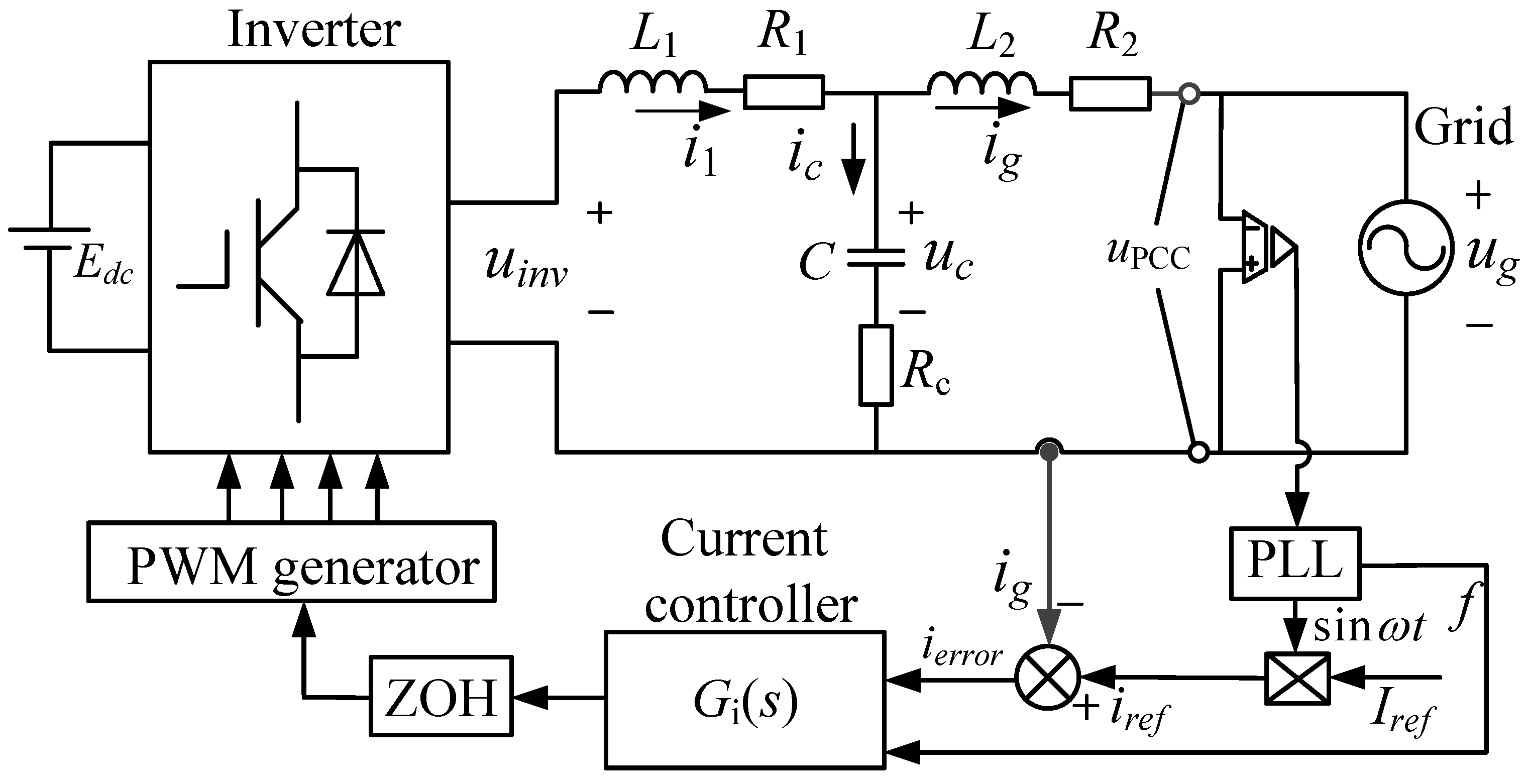
Figure 1. Structure model of the single-phase LCL-type grid-tied PWM inverter.
Fractalfract 07 00848 g001
Figure 2. Structural diagram of the grid current closed-loop control system.
Fractalfract 07 00848 g002
Figure 3. Structural diagram of CRC.
Fractalfract 07 00848 g003
Figure 4. Structural diagram of the PIMR-RC system.
Fractalfract 07 00848 g004
Figure 5. Structural diagram of the PIMR-MRC system.
Fractalfract 07 00848 g005
Figure 6. Structural diagram of equivalent single sampling rate system.
Fractalfract 07 00848 g006
Figure 7. Phase lead compensation angle θ of z m k with the sampling ratio m = 1, 2, 3, and 4.
Fractalfract 07 00848 g007
Figure 8. Structural diagram of the FPL-PIMR-MRC.
Fractalfract 07 00848 g008
Figure 9. Frequency characteristics of IIR and FIR filters.
Fractalfract 07 00848 g009
Figure 10. The roots of 1 + P 0 ( z m ) = 0 . (a) With different proportional gain. (b) With different sampling rates.
Fractalfract 07 00848 g010
Figure 11. Phase-frequency characteristics of S ( z m ) P 0 ( z m ) z m k with different k.
Fractalfract 07 00848 g011
Figure 12. Nyquist curves of H ( e j ω T m ) . (a) With different RC gains. (b) With different sampling rates.
Fractalfract 07 00848 g012
Figure 13. Bode diagrams of P 0 ( z m ) and S ( z m ) P 0 ( z m ) k r z m k . (a) Amplitude frequency characteristics. (b) Phase frequency characteristics.
Fractalfract 07 00848 g013
Figure 14. Amplitude-frequency characteristic of FPL-PIMR-MRC with different sampling rates.
Fractalfract 07 00848 g014
Figure 15. Steady-state response without RC with m = 1. (a) Waveforms of u g and i g . (b) Spectrum analysis of i g .
Fractalfract 07 00848 g015
Figure 16. Steady-state response of the PIMR-RC system with m = 1, k = 9, and k r = 16. (a) Waveforms of u g and i g . (b) Spectrum analysis of i g .
Fractalfract 07 00848 g016
Figure 17. Steady-state response of the PIMR-MRC system with m = 2, k = 4, and k r = 16. (a) Waveforms of u g and i g . (b) Spectrum analysis of i g .
Fractalfract 07 00848 g017
Figure 18. Steady-state response of the FPL-PIMR-MRC system based on FIR-FL with m = 2, k = 3.7, and k r = 16. (a) Waveforms of u g and i g . (b) Spectrum analysis of i g .
Fractalfract 07 00848 g018
Figure 19. Steady-state response of the FPL-PIMR-MRC system based on IIR-FL with m = 2, k = 3.7, and k r = 16. (a) Waveforms of u g and i g . (b) Spectrum analysis of i g .
Fractalfract 07 00848 g019
Figure 20. Steady-state response of the FPL-PIMR-MRC system based on FIR-FL with m = 4, k = 3.7, and k r = 16. (a) Waveforms of u g and i g . (b) Spectrum analysis of i g .
Fractalfract 07 00848 g020
Figure 21. Steady-state response of the FPL-PIMR-MRC system based on IIR-FL with m = 4, k = 3.7, and k r = 16. (a) Waveforms of u g and i g . (b) Spectrum analysis of i g .
Fractalfract 07 00848 g021
Figure 22. Transient responses of the PIMR-MRC system at different sampling rates. (a) m = 1, k = 9, and k r = 16. (b) m = 2, k = 4, and k r = 16.
Fractalfract 07 00848 g022
Figure 23. Transient responses of the FPL-PIMR-MRC system at different sampling rates. (a) Using FIR-FL, m = 2, k = 3.7, and k r = 18. (b) Using IIR-FL, m = 2, k = 3.7, and k r = 18. (c) Using FIR-FL, m = 4, k = 3.7, and k r = 18. (d) Using IIR-FL, m = 4, k = 3.7, and k r = 18.
Fractalfract 07 00848 g023
Table 1. Parameters for the grid-tied inverter.
ParametersSymbolsValues
DC-link voltage E d c 380 V
RMS value of grid voltage U g 220 V
Inverter side inductor L 1 3.8 mH
Grid side inductor L 2 2.3 mH
CapacitorC10 μ F
L 1 equivalent resistance R 1 0.48 Ω
L 2 equivalent resistance R 2 0.32 Ω
Passive damping resistance R c 10 Ω
Grid frequency f g 50 Hz
Switching frequency f s w 10 kHz
Sampling frequency f s 10 kHz
Switching dead time3 μ s
Table 2. Coefficients of the IIR filter when M = 1, 2, 3, 4, and 5.
M = 1 M = 2 M = 3 M = 4 M = 5
a 1 1 d 1 + d 2 ( d 2 ) d + 1 3 ( d 3 ) d + 1 4 ( d 4 ) d + 1 5 ( d 5 ) d + 1
a 2 ( d 1 ) ( d 2 ) ( d + 1 ) ( d + 2 ) 3 ( d 2 ) ( d 3 ) ( d + 1 ) ( d + 2 ) 6 ( d 3 ) ( d 4 ) ( d + 1 ) ( d + 2 ) 10 ( d 4 ) ( d 5 ) ( d + 1 ) ( d + 2 )
a 3 ( d 1 ) ( d 2 ) ( d 3 ) ( d + 1 ) ( d + 2 ) ( d + 3 ) 4 ( d 2 ) ( d 3 ) ( d 4 ) ( d + 1 ) ( d + 2 ) ( d + 3 ) 10 ( d 3 ) ( d 4 ) ( d 5 ) ( d + 1 ) ( d + 2 ) ( d + 3 )
a 4 ( d 1 ) ( d 2 ) ( d 3 ) ( d 4 ) ( d + 1 ) ( d + 2 ) ( d + 3 ) ( d + 4 ) 5 ( d 2 ) ( d 3 ) ( d 4 ) ( d 5 ) ( d + 1 ) ( d + 2 ) ( d + 3 ) ( d + 4 )
a 5 ( d 1 ) ( d 2 ) ( d 3 ) ( d 4 ) ( d 5 ) ( d + 1 ) ( d + 2 ) ( d + 3 ) ( d + 4 ) ( d + 5 )
Disclaimer/Publisher’s Note: The statements, opinions and data contained in all publications are solely those of the individual author(s) and contributor(s) and not of MDPI and/or the editor(s). MDPI and/or the editor(s) disclaim responsibility for any injury to people or property resulting from any ideas, methods, instructions or products referred to in the content.