Article

A New Intelligent Fractional-Order Load Frequency Control for Interconnected Modern Power Systems with Virtual Inertia Control

1
Electrical Engineering Department, Faculty of Engineering, University of Tabuk, Tabuk 47913, Saudi Arabia
2
Renewable Energy & Energy Efficiency Centre (REEEC), University of Tabuk, Tabuk 47913, Saudi Arabia
3
Department of Electrical Engineering, Faculty of Engineering, Aswan University, Aswan 81542, Egypt
4
Faculty of Engineering, King Salman International University, El-Tor 46511, Egypt
5
Department of Electrical Engineering, Faculty of Energy Engineering, Aswan University, Aswan 81528, Egypt
6
Electrical Engineering Department, Faculty of Engineering, Sohag University, Sohag 82524, Egypt
7
Mechanical Engineering Department, Faculty of Engineering, University of Tabuk, Tabuk 47913, Saudi Arabia
*
Author to whom correspondence should be addressed.
Fractal Fract. 2023, 7(1), 62; https://doi.org/10.3390/fractalfract7010062
Submission received: 13 December 2022 / Revised: 28 December 2022 / Accepted: 2 January 2023 / Published: 5 January 2023

Abstract

:
Since modern power systems are susceptible to undesirable frequency oscillations caused by uncertainties in renewable energy sources (RESs) and loads, load frequency control (LFC) has a crucial role to get these systems’ frequency stability back. However, existing LFC techniques may not be sufficient to confront the key challenge arising from the low-inertia issue, which is due to the integration of high-penetration RESs. Therefore, to address this issue, this study proposes an optimized intelligent fractional-order integral (iFOI) controller for the LFC of a two-area interconnected modern power system with the implementation of virtual inertia control (VIC). Here, the proposed iFOI controller is optimally designed using an efficient metaheuristic optimization technique, called the gray wolf optimization (GWO) algorithm, which provides minimum values for system frequency deviations and tie-line power deviation. Moreover, the effectiveness of the proposed optimal iFOI controller is confirmed by contrasting its performance with other control techniques utilized in the literature, such as the integral controller and FOI controller, which are also designed in this study, under load/RES fluctuations. Compared to these control techniques from the literature for several scenarios, the simulation results produced by the MATLAB software have demonstrated the efficacy and resilience of the proposed optimal iFOI controller based on the GWO. Additionally, the effectiveness of the proposed controller design in regulating the frequency of interconnected modern power systems with the application of VIC is confirmed.

1. Introduction

Nowadays, renewable energy sources (RESs) are increasingly being integrated into utility power systems. RESs have the advantages of being clean, infinite, and inexpensive energy sources [1,2]. However, RESs can cause some issues and challenges for utility grids. One of these challenges is the reduction in the inertia of interconnected power systems caused by the incorporation of RESs into modern interconnected power systems. Usually, RESs are interfaced with the utility grid via power converters. These converters have been proven to cause an inertia drop in the power system. Consequently, the frequency and voltage stability of the power system are altered. Therefore, the main obstacle to RESs penetration in modern interconnected power systems is the drop in power system inertia [3,4].
To counteract the reduction of system inertia, creating more inertia virtually is one solution to stabilize the frequency and voltage of modern power systems. This phenomenon of virtual inertia is denominated as a virtual inertia control (VIC) or virtual synchronous generator [5]. The concept of VIC in modern power systems can be established using the inverter-based energy storage system (ESS) and the suitable control technique. Therefore, several applications related to the VIC concept have been presented in the Refs. [6,7,8,9]. The derivative control approach represents one of the most efficient VIC techniques to enhance the frequency stability of modern power systems by establishing virtual inertia [9]. Additionally, in the framework of the VIC system, the derivative control technique is integrated into the proportional–integral (PI) controller [5], and the H_infinity technique [6,8] has been provided for the frequency stability improvement of modern power systems with high RES penetration.
On the other hand, a considerable drop in system frequency occurs in conjunction with a change in load demand when the power system, in particular, a microgrid operates independently, thus endangering the integrity of such systems. It is possible to restore the power system frequency to the desired value by ensuring a match between generation and demand, which is greatly facilitated by implementing load frequency control (LFC). Therefore, many control techniques have been used for the LFC of modern power systems, such as conventional proportional-integral-derivative (PID) controllers [10], fuzzy logic control [11], model predictive control [12], sliding mode control [13], and others. Recently, control systems engineering has paid great attention to fractional calculus approaches that have excellent facilities for control applications. One of these approaches is the fractional-order (FO) approach. The controller used in that approach is called the FO controller (FOC). A new version of the FOC, called intelligent FOC (iFOC), has just been introduced [14]. The multiresolution analysis introduced robust tuning and an excellent response of the closed-loop systems, which are the main advantages of the iFOC [15]. Tuning the iFOC control parameters is the original challenge of its application. Many tuning techniques have been introduced for tuning iFOC, such as auto-tuning, analytic tuning, numerical tuning, and rule-based tuning [16]. However, the optimal response of the iFOC could be achieved using mathematical optimization algorithms [17].
Many optimization algorithms are proposed to tune the controller parameters [18,19,20]. Those algorithms have produced good responses. However, their convergence speed, objective functions, and complexity differed. Recently, a metaheuristic optimization technique called Gray Wolf Optimization (GWO) has been introduced [21]. Due to its simplicity, the GWO algorithm has too many applications in power system control and mechatronics [22]. The GWO has great merit over other optimization techniques. It is considered flexible, uses few variables, has a comprehensiveness feature, and has simple programming and implementation. Furthermore, an adaptive fuzzy PID controller based on a modified GWO algorithm has been proposed for the frequency regulation of hybrid power systems [23], where the optimal designed controller has been performed using different optimization techniques to demonstrate the superiority of the GWO algorithm.
Motivated by these aforementioned observations, this study proposes an intelligent fractional-order integral (iFOI) controller for the LFC of a two-area interconnected modern power system with the implementation of VIC, where ultralocal model (ULM) control is incorporated into the LFC based on an FOI controller to enhance the frequency stability of interconnected modern power systems. Moreover, the design of the proposed controller considers high penetration levels of RESs and system nonlinearities. In contrast, previous LFC techniques may not be sufficient to confront the key challenge arising from the low-inertia issue, which is due to the integration of high-penetration RESs. Therefore, this paper proposes an optimized iFOI controller in conjunction with VIC technology to strongly enhance the frequency stability of a two-area interconnected power system considering the high penetration of RESs. Moreover, the optimal proposed controller is fine-tuned using an efficient metaheuristic optimization technique, that is, the GWO algorithm. Furthermore, the effectiveness of the proposed iFOI controller is confirmed by contrasting its performance with other control techniques utilized in the literature, such as the integral (I) controller [1] and the FOI controller, which were designed beside the proposed controller in this study, under load/RESs fluctuations.
The rest of this paper is presented as follows. The modelling and description of the proposed two-area test system are described in Section 2. In Section 3, the proposed iFOI controller-based LFC is explained. Section 3 discusses the optimization approach based on the GWO. Section 4 provides the simulation results. Finally, the research conclusions are presented in Section 5.

2. System Description and Modeling

Figure 1 presents the structure of the investigated two-area interconnected modern power system integrated with the VIC strategy. The two areas have been interconnected through a power transmission line called the tie-line. Each area has a thermal power plant, load, and VIC based on ESS. In addition, photovoltaic (PV) solar and wind farms have been included in areas 1, and 2, respectively. The first area has a solar farm of 8 MW, however, the second area has a wind farm of 6 MW. The system controller deals with the frequency and tie-line power of the two areas. Then, it generates the control signals for each area.
To model the studied system, the low-order models of the individual generation units may be considered suitable for controlling interconnected power systems [1]. The linear model of the studied two-area interconnected power system with the VIC technology is shown in Figure 2. Additionally, the model parameters are presented in Table 1. Each area has a domestic load that is treated as a disturbance in the model. Wind and solar farms are also treated as disturbances. The deviation in the frequency of the proposed interconnected power system of the j-th area considering the impact of droop control, LFC, and VIC can be represented as follows:
Δ f j = 1 2 H j s + D j Δ P m j + Δ P W T j + Δ P P V j + Δ P I n e r t i a j Δ P L j Δ P T i e , j k
where:
Δ P m j = 1 1 + s T t j Δ P g j
Δ P g j = 1 1 + s T g j Δ P A C E , j 1 R j Δ f j
Δ P W T j = 1 1 + s T W T j Δ P W i n d , j
Δ P P V j = 1 1 + s T P V j Δ P S o l a r , j
where ΔPmj and ΔPgj denote the power produced in area j by the relevant thermal generation system and turbine system, respectively. The area control error (ACE) is determined as the linear combination of the weighted frequency variation and the tie-line power flow, as follows [1,9].
Δ P A C E , j = A C E j s = K j s β j f j + 1 s Δ P T i e , j
The tie-line power deviation between the j-area and the remaining areas can be calculated to create the interconnections among m areas in an interconnected power system,
Δ P T i e , j = k = 1 k j m Δ P T i e , j k = 2 π s k = 1 k j m T j k Δ f j k = 1 k j m T j k Δ f k
where Tjk is the coefficient of synchronization between areas and ΔPTie,jk denotes the area-j and area-k tie-line power exchange.
The linearized state-space model of the proposed power system may be derived using state variables from (1) to (7):
X ˙ = A X + B U + E W
Y = C X + D U + F W
where:
X T = f 1 P g 1 p m 1 P P V P I n e r t i a , 1 P T i e , 12 f 2 P g 2 p m 2 p W T P I n e r t i a , 2
U T = P A C E , 1 P A C E , 2
W T = P S o l a r P W i n d P L 1 P L 2
Y T = f 1 f 2
Thus, U is the ACE signal for the considered power system, W is the input perturbations (i.e., loads and RESs) vector, Y is the output, and X is the state vector of the considered system (i.e., frequency deviation for each area). While E stands for the disturbance inputs, B is for the control output signal, D is for the zero vector of the same size as the controlled signal, F is for the zero vector of the same size as the disturbance input vector, and C is for the output of the system. As a result, it is possible to obtain the full matrices of the state space representation of the proposed two-area interconnected power system considering RESs as below: A = D 1 2 H 1 0 1 2 H 1 1 2 H 1 1 2 H 1 1 2 H 1 0 0 0 0 0 1 R 1 T g 1 1 T g 1 0 0 0 0 0 0 0 0 0 0 1 T t 1 1 T t 1 0 0 0 0 0 0 0 0 0 0 0 1 T P V 0 0 0 0 0 0 0 D 1 K V I 1 2 H 1 T V I 1 0 K V I 1 2 H 1 T V I 1 K V I 1 2 H 1 T V I 1 K V I 1 2 H 1 T V I 1 1 T V I 1 K V I 1 2 H 1 T V I 1 0 0 0 0 0 2 T 12 0 0 0 0 0 2 T 12 0 0 0 0 0 0 0 0 0 12 2 H 1 D 2 2 H 2 0 1 2 H 2 1 2 H 2 1 2 H 2 0 0 0 0 0 0 1 R 2 T g 2 1 T g 2 0 0 0 0 0 0 0 0 0 0 1 T t 2 1 T t 2 0 0 0 0 0 0 0 0 0 0 0 1 T W T 0 0 0 0 0 0 12 K V I 2 2 H 2 T V I 2 D 2 K V I 2 2 H 2 T V I 2 0 K V I 2 2 H 2 T V I 2 K V I 2 2 H 2 T V I 2 K V I 2 2 H 2 T V I 2 1 T V I 2
B = 0 0 1 T g 1 0 0 0 0 0 0 0 0 0 0 0 0 1 T g 2 0 0 0 0 0 0 E = 0 0 1 2 H 1 0 0 0 0 0 0 0 0 0 1 T P V 0 0 0 0 0 K V I 1 2 H 1 T V I 1 0 0 0 0 0 0 0 0 1 2 H 2 0 0 0 0 0 0 0 0 0 1 T W T 0 0 0 0 0 K V I 1 2 H 1 T V I 1
C = 1 0 0 0 0 0 1 0 0 0 0

3. Proposed Intelligent Fractional-Order Integral Controller for LFC

3.1. Fractional-Order Controller

With the use of fractional operators in the controller, any real number can be represented as a general differential or integral notation [24]. The basic mathematical relation of the FO differentiator may be seen as a common form of differential or integral operators, and this can be expressed as follows:
D l , u q = d d d t q   q > 0 1   q = 0 l u d τ q   q < 0
where q is the FO operator, and u and l denote the upper and lower bands, respectively. Two theories can be used to define the FO principle, and one of them is Riemann–Liouville (RL), which is the first method used to determine the order derivative of a function f(t), as given below [25,26]:
D l , u q f t = 1 Γ n q d d t n l u f n τ t τ q n + 1 d τ
where Γ z = 0 t z 1 e t d t ,   z > 0 is the function of Gamma and the variable q is limited as n − 1 < q < n.
After a fractional derivative of RL is found in (11), it can be transformed by the Laplace method as shown in (12) [27]. Additionally, there is the definition of Caputo as a second definition associated with the concept of FO by which we can express the time-domain representation of the a order of the function f(t) as in (13).
L D 0 a f t = s a F s y = 0 n 1 s y D 0 a y 1 f t | t = 0
D t 0 t f t = 1 Γ n a t 0 t f n τ t τ 1 n a d τ   n 1 < a < n d d t n f t   a = n
A physical meaning for the integral order can be understood by looking at (14), which is a Laplace transformation of (13). Therefore, the integral order has an initial condition that indicates its physical meaning.
L D 0 a f t = s a F s k = 0 n 1 s a k 1 f k 0
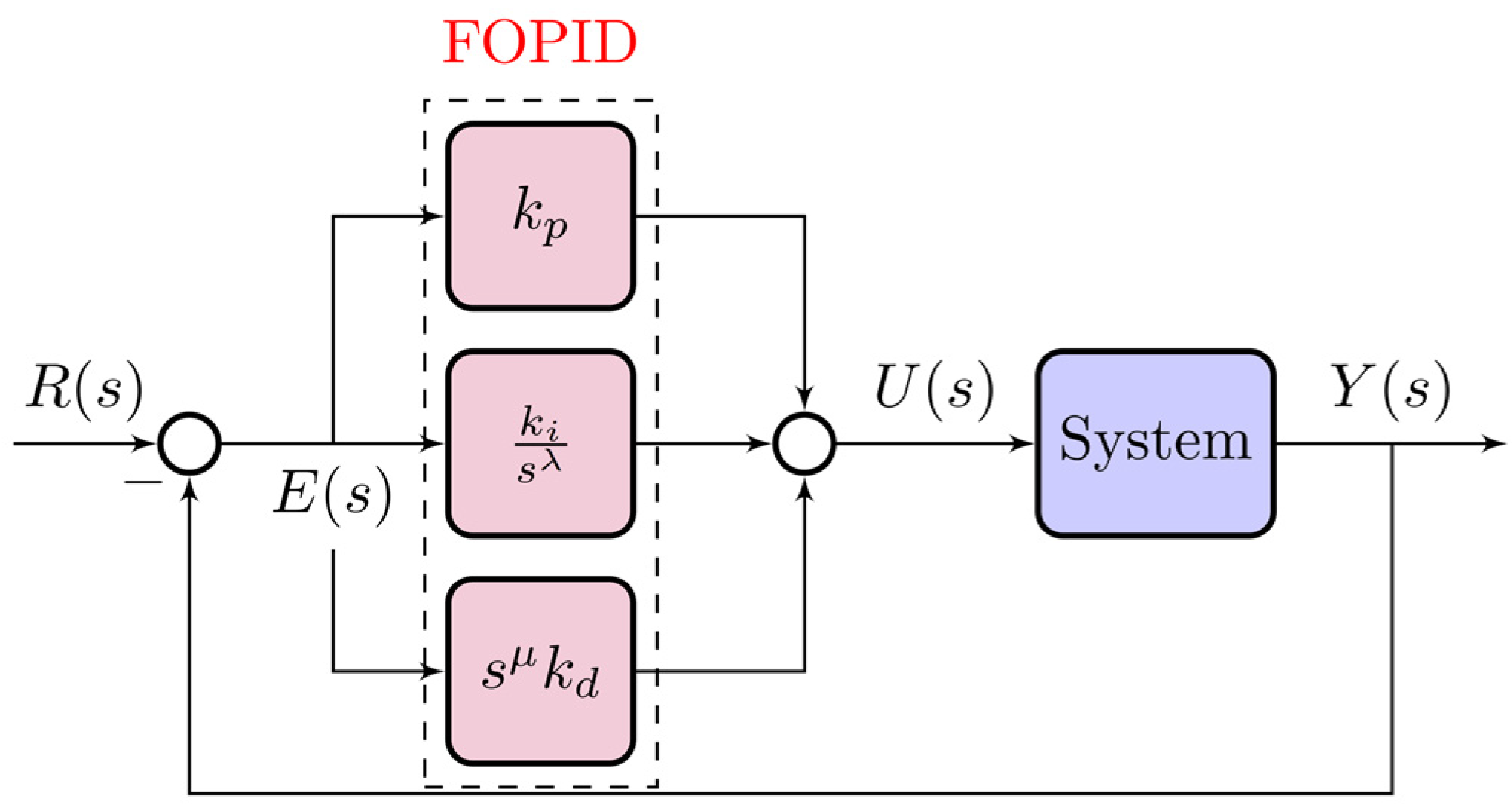
A FOPID controller consists of five parameters, including two additional parameters of integral and fractional order, as shown in Figure 3, which is given in terms of the integral and fractional order of the parameters. The complete transfer function of the FOPID is given in (15). It has been proven that these parameters can increase the controller’s transient time, stability, and steady-state error compared to a traditional PID. Additionally, it provides the controller with more flexibility, allowing it to cope with a wide range of system disturbances:
G c s = k p + k i 1 s λ + k d s μ
where λ and μ are frequently in the [0, 1] range.

3.2. Ultra-Local Model Control

The changes in the single-input single-output (SISO) system may be approximated with the help of a differential equation with finite dimensionality as in Refs. [28,29]:
E t , y , y 1 , , y n , u , u 1 , , u m = 0
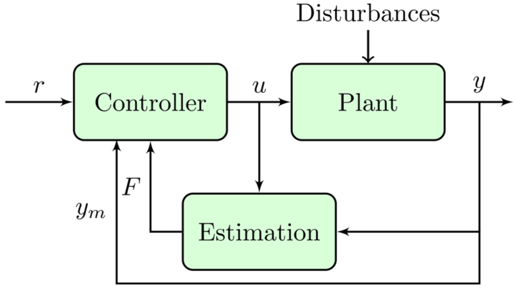
where E represents a non-linear function, u indicates the system’s input, y indicates the system’s output, and (n, m) specify the control orders of the system’s output and input, respectively. Figure 4 shows the basic structure of the ULM in general, where F is the ULM total uncertainties and disturbance of the system. Measurement of the system output and prior control input determines the unknown function F. In addition, it is possible to simplify (16) using the ULM principle as follows:
y n = F + α u
where y n denotes the nth derivative of y (i.e., the practitioner typically selects n equal to 1 or 2, with 1 being the case in all real-world situations [29]), and α ∈ R represents a non-physical parameter.
Since the value of F is only an estimate and lacks precision, it can be substituted with the letter F ^ to represent the estimated value when using identification techniques [30]:
F ^ t = 3 ! L 3 t L t L 2 σ y σ + α σ L σ u σ d σ
where L has a small value based on the noise intensity and the sampling period Ts. Finally, the Heun method can be used to find the value of F ^ as in (12), where Nf is the window length.
F ^ = 3 N f 3 T s i = 1 N f A + B
where
A = N f 2 i 1 y k 1 + N f 2 i y k
B = α i 1 T s N f i 1 u k 1 + α i T s N f i u k

3.3. Proposed iFOI for LFC

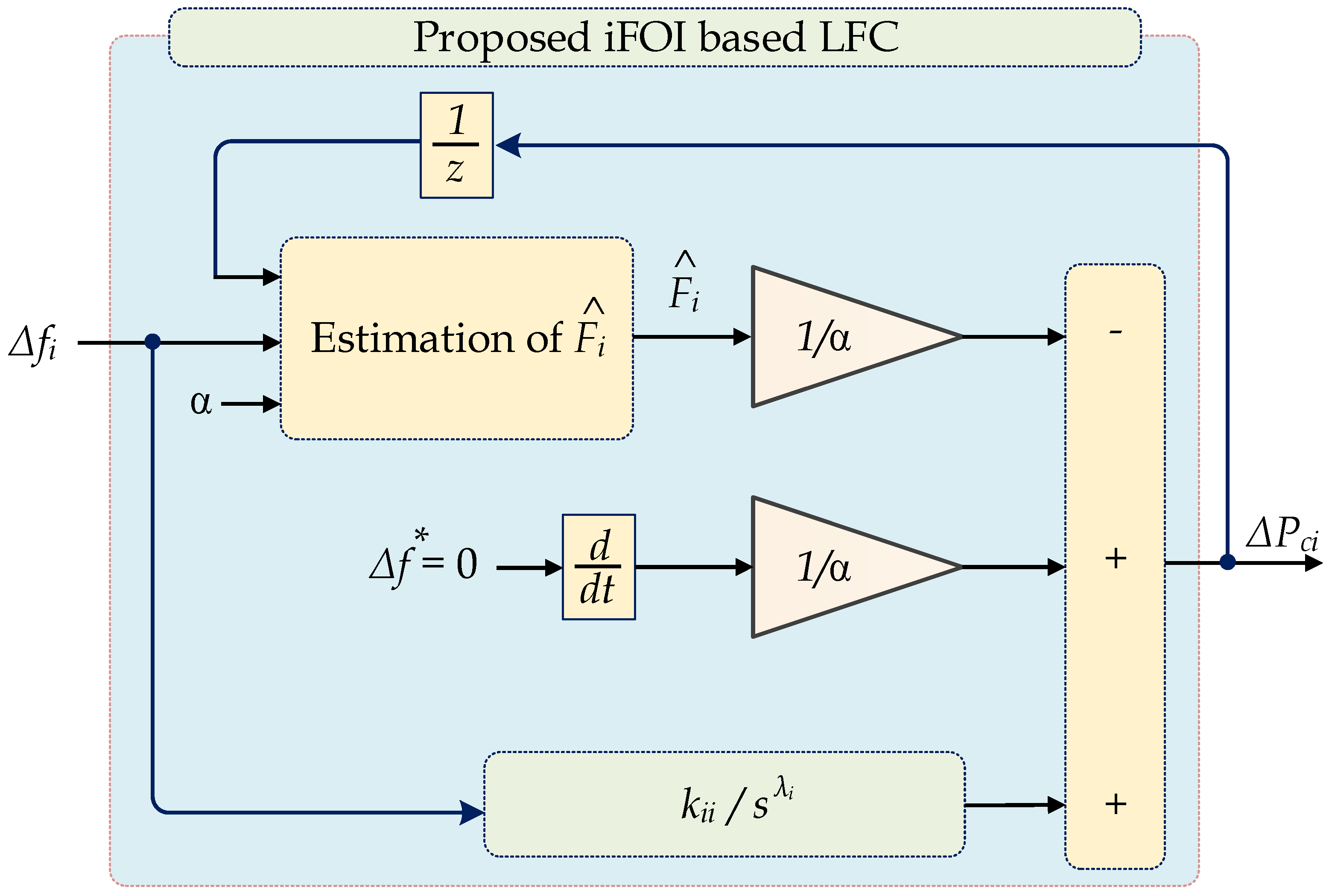
The secondary controller’s goal is to keep the system’s frequency at its nominal value within a few minutes after a disturbance. As a result of the great stability and robustness of the FO-based I controller, it has been widely applied for power system stability, whereas most studies have focused on controlling the LFC of power systems [31]. In the current work, Figure 5 indicates the ULM part is incorporated into the FOI controller to reduce the frequency deviation Δf. Hence, the overall structure of the controller may be named an intelligent integral (i.e., iFOI) because it avoids the need for a model to be applied to the controller. This control strategy makes it possible to get rid of the parameter mismatches that cause the power system to malfunction. The incremental power of each area ΔPci, which represents the control input of the proposed controller, is formulated as in (20) where s is the Laplace operator.
P c i = F ^ i α i + k i i 1 s λ i f i
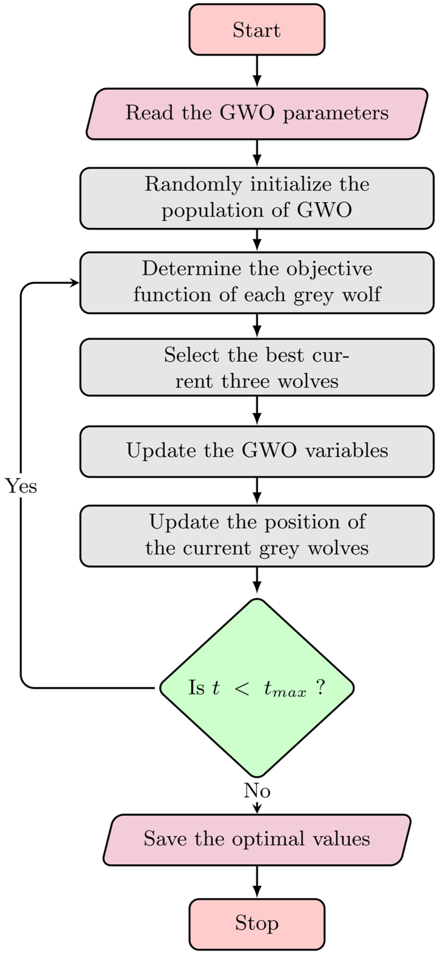
The trial-and-error methodology can be used to define the iFOI parameter, making the tuning process challenging and practitioner-dependent. It is also challenging to find the ideal parameter value for the proposed iFOI, which enhances system performance and ensures the system’s stability against disturbances using these trial-and-error methods, and thus the robustness of the system goes down. Therefore, in this paper, to find the best value for the parameter of the iFOI controller of each area, a metaheuristic optimization approach based on GWO is employed, and the complete tuning process of the entire system is shown in Figure 6. The main flowchart of the GWO approach is sketched in Figure 7. The maximum iteration of the GWO is set at 100 and the number of grey wolves is 50.

4. Simulation Results

The proposed two-area interconnected power system with the VIC technique and the proposed iFOI controller, presented in Figure 2, is simulated using the Matlab/Simulink platform with the technical parameters shown in Table 1. However, the optimal gains of the FOI and the proposed iFOI for each area are summarized in Table 2. The results have been extracted into four scenarios or cases. The system has a step-change in load with a uniform RESs profile in the first scenario. The second scenario considers a step load change with a random RES profile. The system has a random load with a uniform RES profile in the third case. The fourth case provides that the system has a random load change with a random RESs profile. Three controllers are compared for each scenario. The compared three controllers are the proposed iFOI, the FOI which is designed beside the proposed controller in this study, and the conventional I controller [1]. The detailed results and discussion are found in the next few paragraphs.

4.1. Case 1: Fixed Load Step Change and Uniform RESs Profile

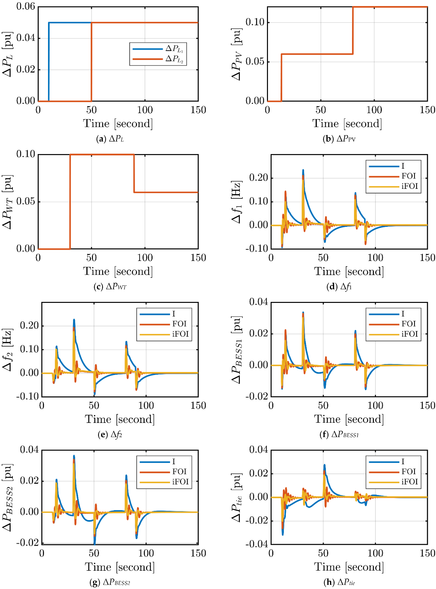
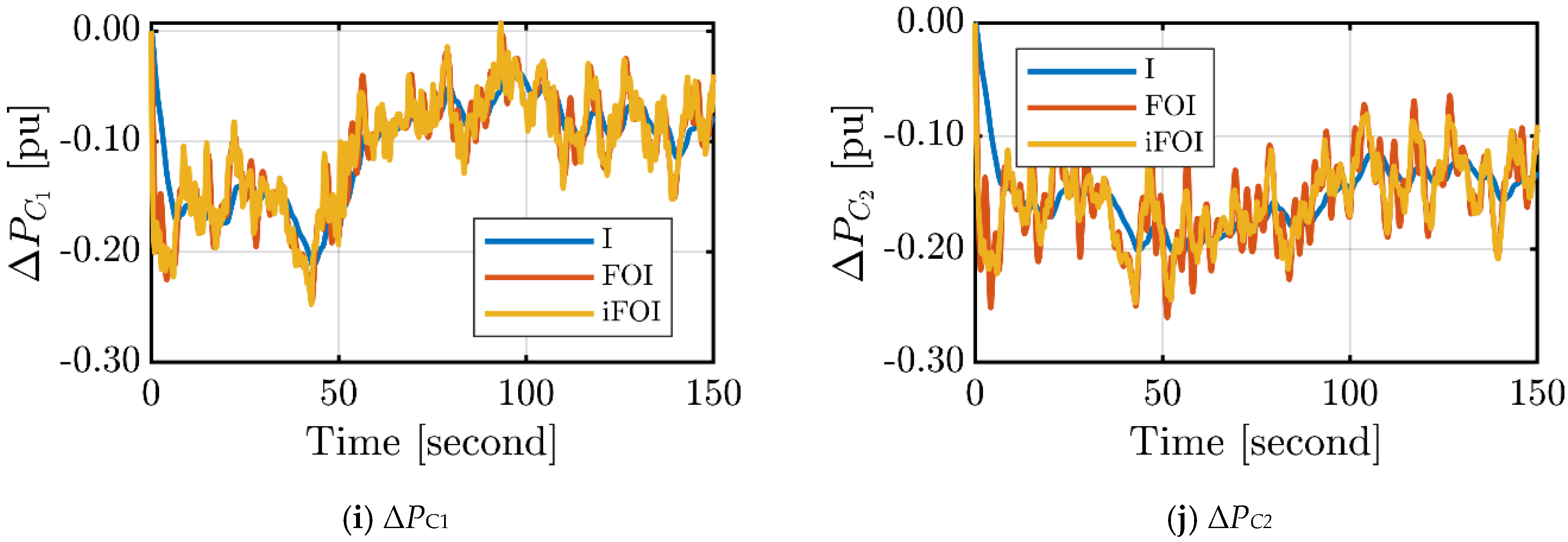
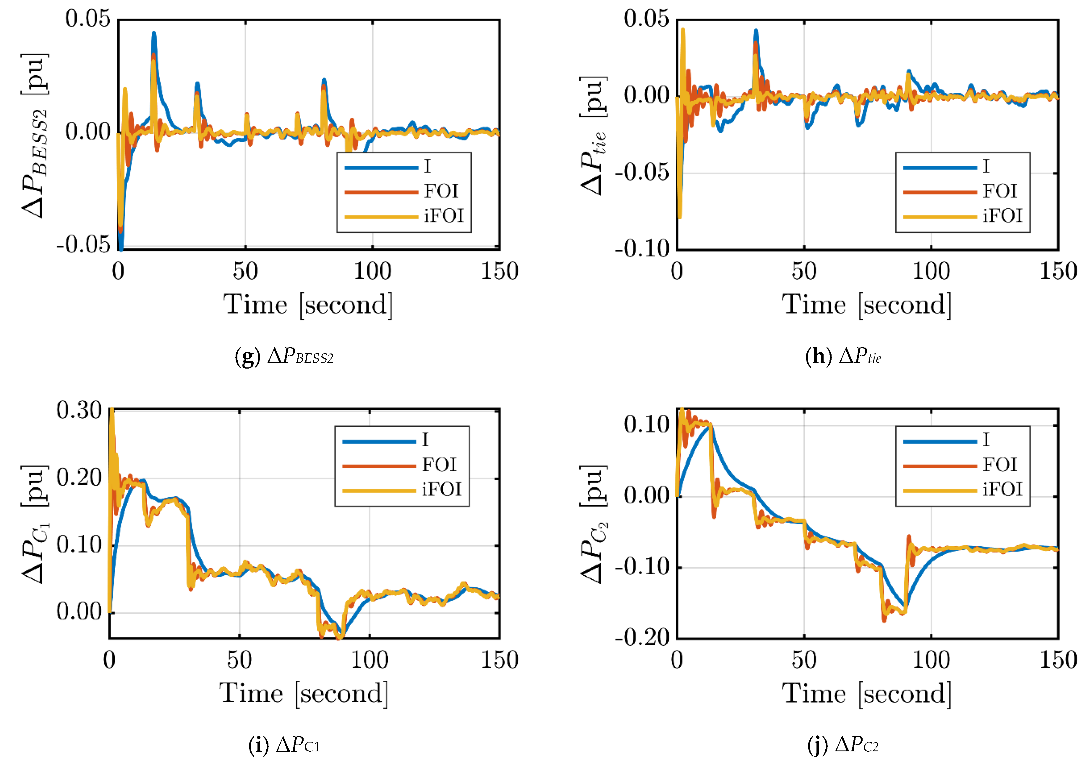
The loads’ profiles for the two areas in this scenario are shown in Figure 8a. Each load has a 0.5 pu step change, but it happens at different times. Figure 8b,c shows the generation profiles of the PV and wind energy sources, respectively. They have uniform step variations at different times. The peak power output from the solar panels in Area 1 is 0.125 pu, while the peak power output from the wind turbines in area 2 is 0.1 pu. Figure 8d,e shows the frequency deviation in the two areas under different controllers. The conventional integral controller has the worst response with high overshoots and slow responses. However, the proposed iFOI has the best responses in these two areas. Additionally, the frequency deviations remained within the recommended ranges when the load change is rather minimal. Additionally, the iFOI has the best performance over the other controllers. The change in BESS power is presented in Figure 8f,g, which is controlled based on the virtual inertia control. The variation in the tie-line power exchange between the two areas is shown in Figure 8h. The control output of the LFC controller of each area, which represents the incremental power to the governor, is shown in Figure 8i,j. It is clear that ΔPCi with the proposed iFOI follows the dynamic of the load and RES changes with minimum oscillations. The overall response of the interconnected system performs best with the proposed iFOI.

4.2. Case 2: Fixed Load Step Change and Random RESs Profile

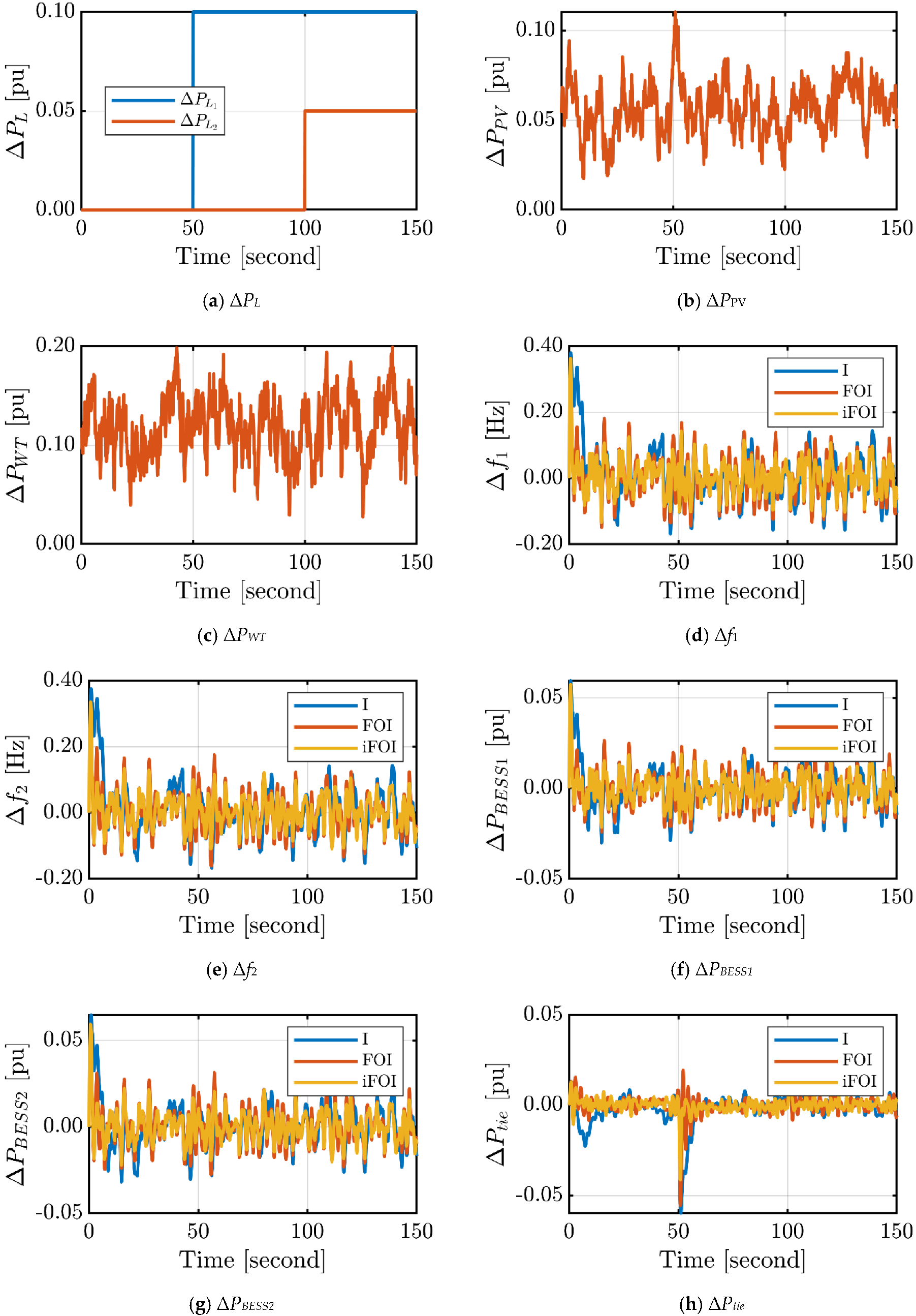
In this case, the loads’ profiles, for the two areas, are shown in Figure 9a. The loads have 0.1 pu and 0.05 pu steps, respectively, but at different times. The considered loads are uniform over time. Additionally, the generation profiles of the PV and wind energy sources are presented in Figure 9b,c, respectively. The PV power has a random variation limited to 0.02 pu < ΔPPV < 0.12 pu. In the other area, the wind power has a random variation limited to 0.03 pu < ΔPWT < 0.2 pu. Figure 8d,e shows the frequency deviation in the two areas under different controllers. The conventional integral controller has the worst response of high overshoots and slow response. Nevertheless, the iFOI has the best responses in the two areas where it provides the minimum variations in the Δf of each area compared to other controllers. Additionally, the iFOI has the best performance over the other controllers. The change in the power of the BESS is presented in Figure 9f,g. The variation in the tie-line power exchange between the two areas is shown in Figure 9h. Moreover, the control output of the LFC controller of each area is shown in Figure 9i,j. With both FO controllers, ΔPCi has the same dynamics of changes similar to the RES changes. The overall response of the interconnected system performs best with the proposed iFOI.

4.3. Case 3: Random Load and Uniform RESs

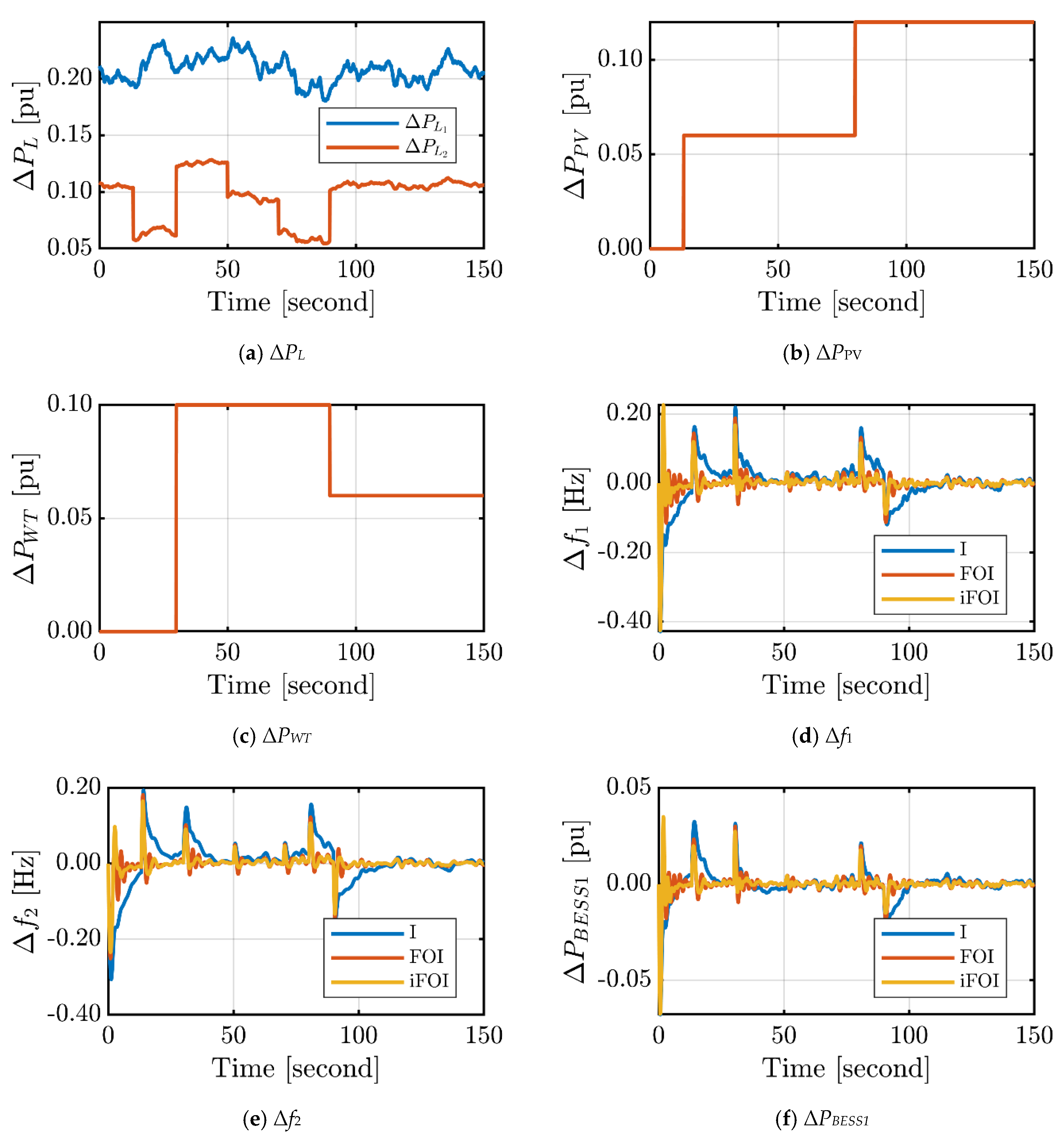
In this case, the load profiles for the two areas are random, as shown in Figure 10a. The first area load variations have been limited to 0.18 pu < ΔPL1 < 0.23 pu. However, the second area load variations have been limited to 0.05 pu < ΔPL2 < 0.13 pu. Additionally, the generation profiles of the PV and wind energy sources are present in Figure 10b,c, respectively. They have step variations at different times. Figure 10d,e shows the frequency deviation in the two areas under different controllers. The conventional integral controller has the worst response of high overshoots and a slow response. It is clear that there is a frequency deviation at a time instant of zero as the load of area 1 and area 2 starts with changes of 0.21 pu and 0.11 pu, respectively. Nevertheless, the iFOI has the best responses in the two areas. Additionally, the iFOI has the best performance over the other controllers. The change in the power of the BESS is presented in Figure 10f,g. The variation in the tie-line power exchange between the two areas is shown in Figure 10h. The LFC controller of each area produces output signals, Figure 10i,j, that indicate the amount of power change that the area is supplying to maintain the system frequency at the nominal value. The overall response of the interconnected system performs best with the proposed iFOI.

4.4. Case 4: Random Load and Random RESs

In this case, the load profiles for the two areas are random, as shown in Figure 11a. The first area load variations have been limited to 0.18 pu < ΔPL1 < 0.23 pu. However, the second area load variations have been limited to 0.05 pu < ΔPL2 < 0.13 pu. Additionally, the generation profiles of the PV and wind energy sources are present in Figure 11b,c. The PV power has a random variation limited to 0.02 pu < ΔPPV < 0.12 pu. In the other area, wind power has a random variation limited to 0.03 pu < ΔPWT < 0.2 pu. Figure 11d,e shows the frequency deviation in the two areas under different controllers. The conventional integral controller has the worst response of high overshoots and slow response. Nevertheless, the iFOI has the best responses in the two areas. Additionally, the frequency deviations were kept within the recommended standards. Additionally, the iFOI has the best performance over the other controllers. The change in BESS power is presented in Figure 11f,g. The variation in the tie-line power exchange between the two areas is shown in Figure 10h. Furthermore, the control output of the LFC controller for each area is shown in Figure 11i,j. The power change of the controller’s control output is different because each area has different loading and RES penetration levels. The overall response of the interconnected system performs best with the proposed iFOI.

4.5. Objective Function Analysis for the Previous Four Cases

The objective function based on the integral square error (ISE) of each controller in each studied case is depicted in Figure 12. It is obvious that the proposed iFOI has the minimum value of the objective function compared to the other two controllers in each case. Additionally, case 2 has the highest record of ISE for the three controllers as it has a random RES profile beside the uniform loading in each area. In this case, the proposed iFOI reduces the ISE objective function by 33.67% and 59.18% compared to the LFC according to the FOI controller and the integral controller, respectively.

5. Conclusions

This study proposed an optimized iFOI controller for the LFC of a two-area interconnected modern power system with the implementation of virtual inertia control. Here, the proposed iFOI controller is optimally designed using the gray wolf optimization, which is known as an efficient metaheuristic optimization technique and provides minimum frequency deviations and tie-line power deviation. The effectiveness of the proposed optimal iFOI controller is confirmed by contrasting its performance with other control techniques utilized in the literature, such as the integral controller and the FOI controller. The performance of the two-area power system has been tested under load/RESs fluctuations. Compared to these control techniques from the literature for several scenarios, the simulation results produced by the MATLAB software demonstrated the efficacy and resilience of the proposed optimal iFOI controller based on the GWO. Nevertheless, the iFOI had the best responses in the two areas. Additionally, the frequency deviations were kept within the recommended standards. The results from all scenarios show that the overall response of the interconnected system performs best with the proposed iFOI, compared to the integral controller and the FOI controller. On the other hand, the objective functions for the controllers used with the studied scenarios have been analyzed based on the basis of the integral square error. It is noticed that the proposed iFOI has the minimum value of the objective function compared to the other two controllers in each scenario.

Author Contributions

A.B., G.M. and S.A.Z. conceived and designed the system, derived the model, and analyzed the results. H.A. (Hossam AbdelMeguid), M.E.E.-S., B.M. and A.M.K. helped with collecting the funding, resources validation, and visualization, and H.A. (Hani Albalawi) supported the manuscript proofreading and writing. All authors have read and agreed to the published version of the manuscript.

Funding

This research was funded by the University of Tabuk, Grant Number S-1443-0018 at https://www.ut.edu.sa/web/deanship-of-scientific-research/home (accessed on 21 August 2022).

Institutional Review Board Statement

Not applicable.

Informed Consent Statement

Informed consent was obtained from all individual participants included in the study.

Data Availability Statement

Data are available from the authors upon reasonable request.

Acknowledgments

The authors extend their appreciation to the Deanship of Scientific Research at the University of Tabuk for funding this work through research no. S-1443-0018.

Conflicts of Interest

The authors declare no conflict of interest.

References

  1. Kerdphol, T.; Rahman, F.S.; Mitani, Y. Virtual Inertia Control Application to Enhance Frequency Stability of Interconnected Power Systems with High Renewable Energy Penetration. Energies 2018, 11, 981. [Google Scholar] [CrossRef] [Green Version]
  2. El-Hendawi, M.; Gabbar, H.; El-Saady, G.; Ibrahim, E.-N. Control and EMS of a Grid-Connected Microgrid with Economical Analysis. Energies 2018, 11, 129. [Google Scholar] [CrossRef] [Green Version]
  3. Deepak, M.; Abraham, R.J.; Gonzalez-Longatt, F.M.; Greenwood, D.M.; Rajamani, H.S. A novel approach to frequency support in a wind integrated power system. Renew. Energy 2017, 108, 194–206. [Google Scholar] [CrossRef] [Green Version]
  4. Magdy, G.; Bakeer, A.; Nour, M.; Petlenkov, E. A New Virtual Synchronous Generator Design Based on the SMES System for Frequency Stability of Low-Inertia Power Grids. Energies 2020, 13, 5641. [Google Scholar] [CrossRef]
  5. Magdy, G.; Shabib, G.; Elbaset, A.A.; Mitani, Y. Renewable power systems dynamic security using a new coordination of frequency control strategy based on virtual synchronous generator and digital frequency protection. Int. J. Electr. Power Energy Syst. 2019, 109, 351–368. [Google Scholar] [CrossRef]
  6. Kerdphol, T.; Rahman, F.S.; Mitani, Y.; Watanabe, M.; Küfeoǧlu, S.K. Robust Virtual Inertia Control of an Islanded Microgrid Considering High Penetration of Renewable Energy. IEEE Access 2018, 6, 625–636. [Google Scholar] [CrossRef]
  7. Magdy, G.; Bakeer, A.; Alhasheem, M. Superconducting energy storage technology-based synthetic inertia system control to enhance frequency dynamic performance in microgrids with high renewable penetration. Prot. Control Mod. Power Syst. 2021, 6, 36. [Google Scholar] [CrossRef]
  8. Fathi, A.; Shafiee, Q.; Bevrani, H. Robust Frequency Control of Microgrids Using an Extended Virtual Synchronous Generator. IEEE Trans. Power Syst. 2018, 33, 6289–6297. [Google Scholar] [CrossRef]
  9. Magdy, G.; Ali, H.; Xu, D. A new synthetic inertia system based on electric vehicles to support the frequency stability of low-inertia modern power grids. J. Clean. Prod. 2021, 297, 126595. [Google Scholar] [CrossRef]
  10. Nour, M.; Magdy, G.; Chaves-Ávila, J.P.; Sánchez-Miralles, Á.; Petlenkov, E. Automatic Generation Control of a Future Multisource Power System Considering High Renewables Penetration and Electric Vehicles: Egyptian Power System in 2035. IEEE Access 2022, 10, 51662–51681. [Google Scholar] [CrossRef]
  11. Khooban, M.H.; Gheisarnejad, M. A Novel Deep Reinforcement Learning Controller Based Type-II Fuzzy System: Frequency Regulation in Microgrids. IEEE Trans. Emerg. Top. Comput. Intell. 2021, 5, 689–699. [Google Scholar] [CrossRef]
  12. Kumar, A.; Kumari, N.; Shankar, G.; Elavarasan, R.M.; Kumar, S.; Srivastava, A.K.; Khan, B. Load Frequency Control of Distributed Generators Assisted Hybrid Power System Using QOHSA Tuned Model Predictive Control. IEEE Access 2022, 10, 109311–109325. [Google Scholar] [CrossRef]
  13. Khooban, M.-H. Secondary Load Frequency Control of Time-Delay Stand-Alone Microgrids With Electric Vehicles. IEEE Trans. Ind. Electron. 2018, 65, 7416–7422. [Google Scholar] [CrossRef]
  14. Paul, R.; Sengupta, A. Fractional Order Intelligent Controller for Single Tank Liquid Level System. In Proceedings of the 2021 IEEE Second International Conference on Control, Measurement and Instrumentation (CMI), Kolkata, India, 8–10 January 2021; pp. 24–29. [Google Scholar] [CrossRef]
  15. Birs, I.; Muresan, C.; Nascu, I.; Ionescu, C. A Survey of Recent Advances in Fractional Order Control for Time Delay Systems. IEEE Access 2019, 7, 30951–30965. [Google Scholar] [CrossRef]
  16. Shah, P.; Agashe, S. Review of fractional PID controller. Mechatronics 2016, 38, 29–41. [Google Scholar] [CrossRef]
  17. Cao, J.Y.; Liang, J.; Cao, B.G. Optimization of Fractional Order PID controllers based on genetic algorithms. In Proceedings of the International Conference Machine and Learning Cybernetics ICMLC, Guangzhou, China, 18–21 August 2005; Springer: Berlin/Heidelberg, Germany, 2005; pp. 5686–5689. [Google Scholar]
  18. Mosaad, M.I. Direct power control of SRG-based WECSs using optimised fractional-order PI controller. IET Electr. Power Appl. 2020, 14, 409–417. [Google Scholar] [CrossRef]
  19. Ate¸s, A.; Yeroglu, C. Optimal fractional order PID design via Tabu Search based algorithm. ISA Trans. 2016, 60, 109–118. [Google Scholar] [CrossRef]
  20. Kumar, M.R.; Deepak, V.; Ghosh, S. Fractional-order controller design in frequency domain using an improved nonlinear adaptive seeker optimization algorithm. Turkish J. Electr. Eng. Comput. Sci. 2017, 25, 4299–4310. [Google Scholar] [CrossRef]
  21. Mirjalili, S.; Mirjalili, S.M.; Lewis, A. Grey Wolf Optimizer. Adv. Eng. Softw. 2014, 69, 46–61. [Google Scholar] [CrossRef]
  22. Qais, M.H.; Hasanien, H.M.; Alghuwainem, S. A Grey Wolf optimizer for optimum parameters of multiple PI controllers of a grid connected PMSG driven by variable speed wind turbine. IEEE Access 2018, 6, 44120–44128. [Google Scholar] [CrossRef]
  23. Padhy, S.; Panda, S. Application of a simplified Grey Wolf optimization technique for adaptive fuzzy PID controller design for frequency regulation of a distributed power generation system. Prot. Control Mod. Power Syst. 2021, 6, 2. [Google Scholar] [CrossRef]
  24. Mohamed, E.A.; Ahmed, E.M.; Elmelegi, A.; Aly, M.; Elbaksawi, O.; Mohamed, A.-A.A. An Optimized Hybrid Fractional Order Controller for Frequency Regulation in Multi-Area Power Systems. IEEE Access 2020, 8, 213899–213915. [Google Scholar] [CrossRef]
  25. Podlubny, I. Fractional Differential Equations: An Introduction to Fractional Derivatives, Fractional Differential Equations, to Methods of Their Solution and Some of Their Applications; Elsevier: Amsterdam, The Netherlands, 1999. [Google Scholar]
  26. Morsali, J.; Zare, K.; Tarafdar Hagh, M. Applying fractional order PID to design TCSC-based damping controller in coordination with automatic generation control of interconnected multi-source power system. Eng. Sci. Technol. Int. J. 2017, 20, 1–17. [Google Scholar] [CrossRef] [Green Version]
  27. Moschos, I.; Parisses, C. A novel optimal PIλDND2N2 controller using coyote optimization algorithm for an AVR system. Eng. Sci. Technol. Int. J. 2022, 26, 100991. [Google Scholar] [CrossRef]
  28. Fliess, M.; Join, C. Model-free control, and intelligent pid controllers: Towards a possible trivialization of nonlinear control? IFAC Proc. Vol. 2009, 42, 1531–1550. [Google Scholar] [CrossRef] [Green Version]
  29. Michel, L.; Join, C.; Fliess, M.; Sicard, P.; Cheriti, A. Model-free control of dc/dc converters. In Proceedings of the IEEE Workshop on Control and Modeling for Power Electronics (COMPEL), Boulder, CO, USA, 28–30 June 2010. [Google Scholar] [CrossRef] [Green Version]
  30. Thabet, H.; Ayadi, M.; Rotella, F. Experimental comparison of new adaptive PI controllers based on the ultra-local model parameter identification. Int. J. Control Autom. Syst. 2016, 14, 1520–1527. [Google Scholar] [CrossRef] [Green Version]
  31. Saxena, S. Load frequency control strategy via fractional-order controller and reduced-order modeling. Int. J. Electr. Power Energy Syst. 2019, 104, 603–614. [Google Scholar] [CrossRef]
Figure 1. The basic structure of the proposed two-area interconnected power system.
Fractalfract 07 00062 g001
Figure 2. The dynamic model of the studied interconnected two-area power system considering a VIC-based BESS.
Fractalfract 07 00062 g002
Figure 3. The basic structure of the FOPID controller.
Fractalfract 07 00062 g003
Figure 4. The structure of the ultra-local model.
Fractalfract 07 00062 g004
Figure 5. Structure of the proposed iFOI for the secondary controller for each area.
Fractalfract 07 00062 g005
Figure 6. Tuning process of the proposed iFOI.
Fractalfract 07 00062 g006
Figure 7. Flowchart of the metaheuristic GWO algorithm.
Fractalfract 07 00062 g007
Figure 8. Dynamic response of the two-area power system in case 1.
Fractalfract 07 00062 g008aFractalfract 07 00062 g008b
Figure 9. Dynamic response of the two-area power system in case 2.
Fractalfract 07 00062 g009aFractalfract 07 00062 g009b
Figure 10. Dynamic response of the two-area power system in case 3.
Fractalfract 07 00062 g010aFractalfract 07 00062 g010b
Figure 11. Dynamic response of the two-area power system in case 4.
Fractalfract 07 00062 g011aFractalfract 07 00062 g011b
Figure 12. Evaluation of the objective function of each controller for each studied case.
Fractalfract 07 00062 g012
Table 1. Parameters of the two-area interconnected system.
Technical ParameterValue
Area1Area1
System damping coefficient, D (pu)0.0150.016
System inertia, H (pu)0.0830.101
The time constant of the governor, Tg (s)0.0800.060
The time constant of the turbine, Tt (s)0.4000.440
Droop constant, R (pu)3.0002.730
Integral control variable gain, KI0.3000.200
Frequency bias factor, β (pu MW/Hz)0.34830.3827
The time constant of the PV system, TPV (s)1.300-
The time constant of the WT system, TWT (s)-1.500
Virtual inertia control gain, KVI (s)1.5401.750
Virtual inertia time constant, TVI (s)10.00010.000
Nominal system frequency, f (Hz)50.00050.000
Synchronizing coefficient between two areas, Ttie0.0800.080
The capacity ratio between two areas, α12−0.600−0.600
Table 2. Summary of the optimal values of the tested controllers based on GWO.
ControllerParameterValue
Area1Area1
FOIλ0.8080.805
ki−1.367−1.739
Proposed iFOIλ0.6630.734
ki−0.609−0.574
α4.0204.870
Disclaimer/Publisher’s Note: The statements, opinions and data contained in all publications are solely those of the individual author(s) and contributor(s) and not of MDPI and/or the editor(s). MDPI and/or the editor(s) disclaim responsibility for any injury to people or property resulting from any ideas, methods, instructions or products referred to in the content.