
A Compact Triple-Band UWB Inverted Triangular Antenna with Dual-Notch Band Characteristics Using SSRR Metamaterial Structure for Use in Next-Generation Wireless Systems
 , , and
Abstract
:1. Introduction
2. Antenna Configuration
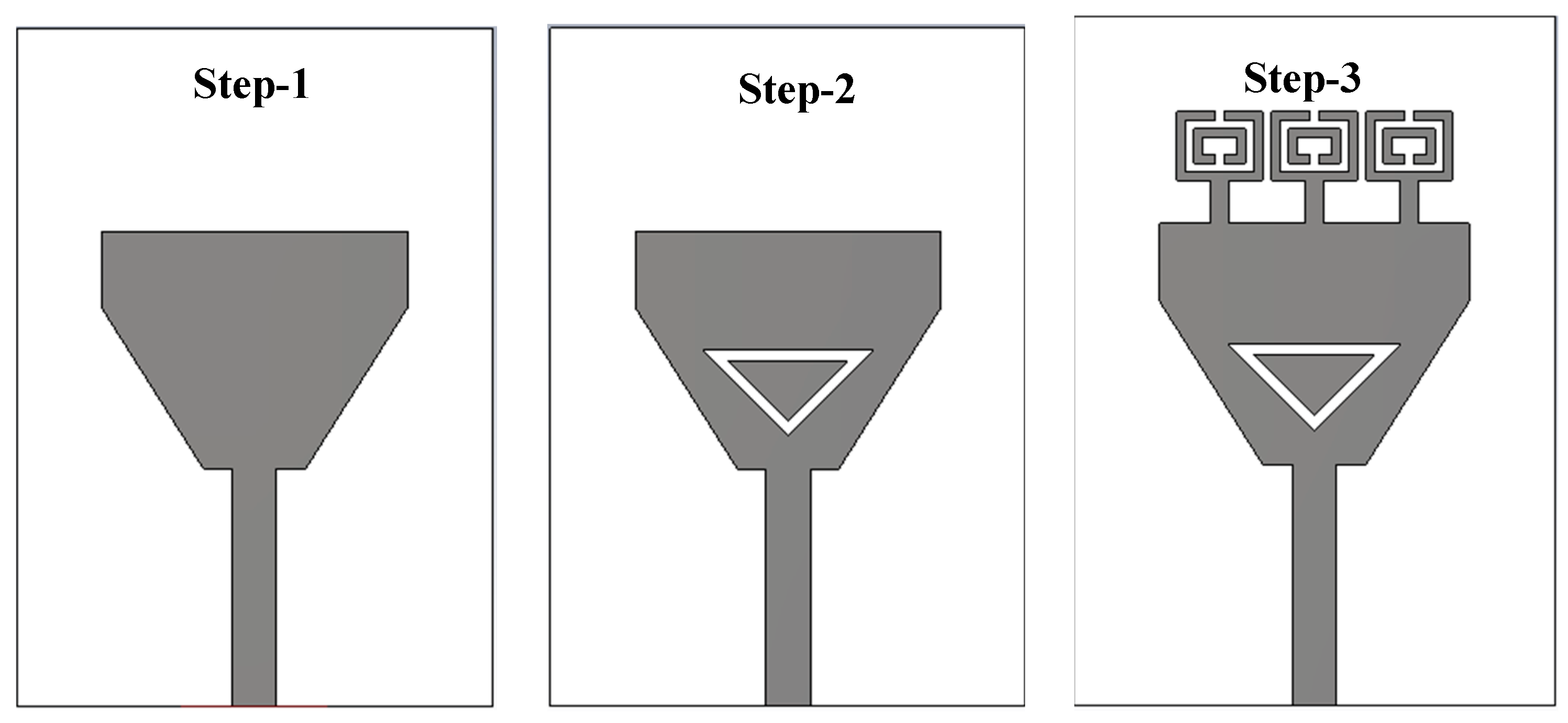
2.1. Antenna Model
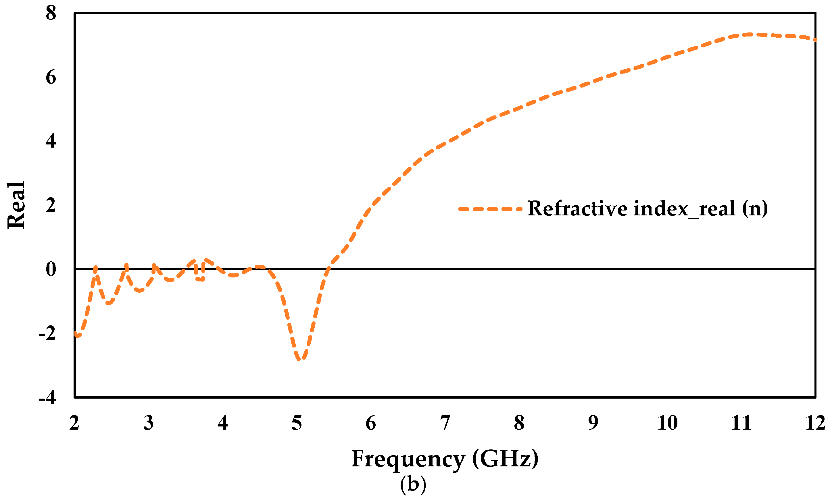
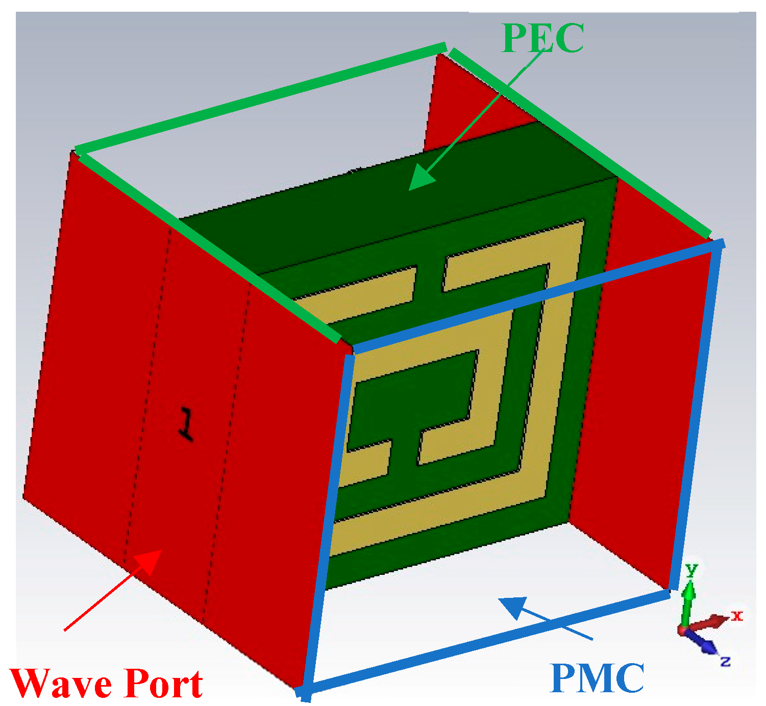
2.2. SSRR Analysis
2.3. Antenna Analysis
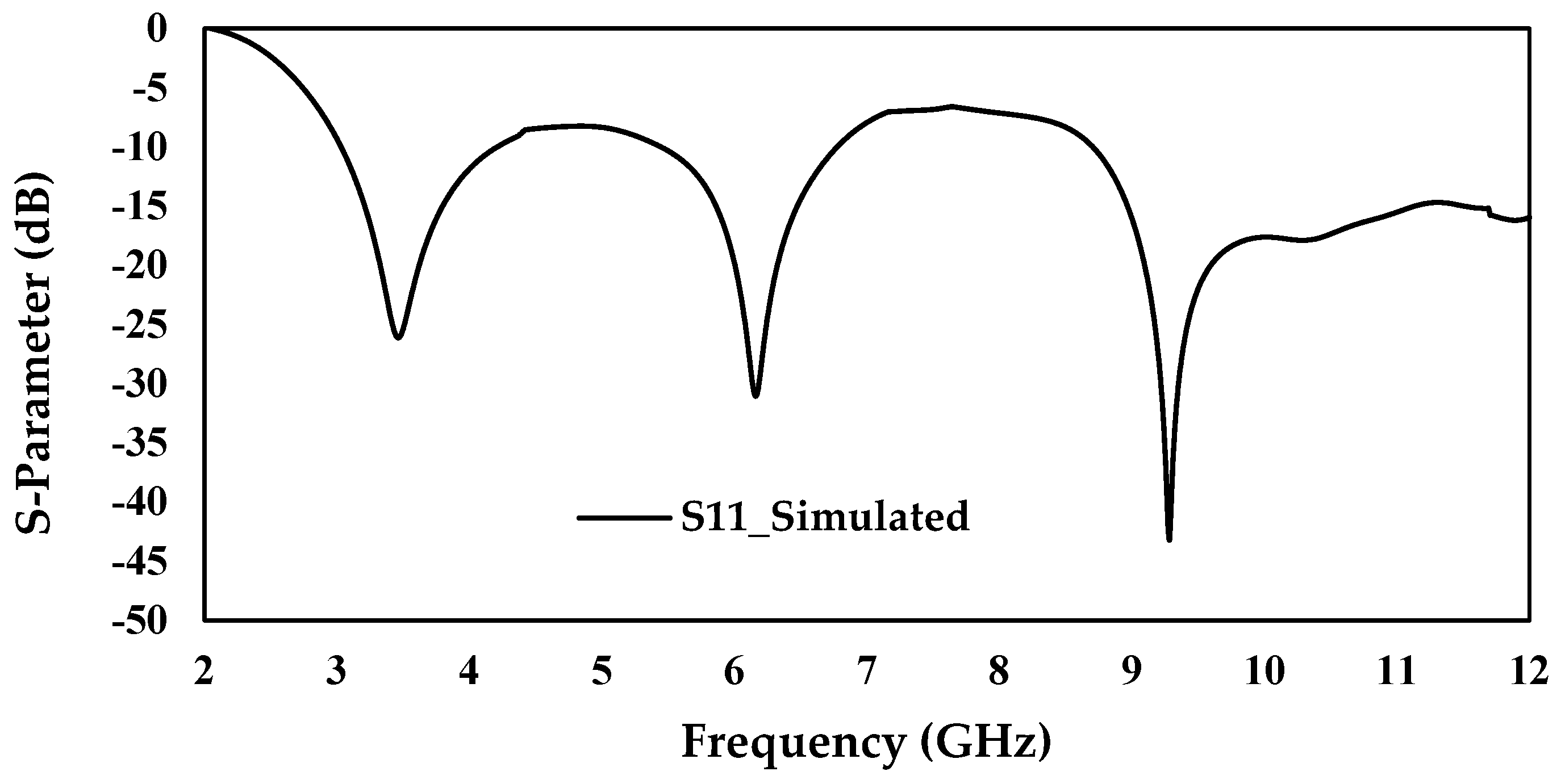
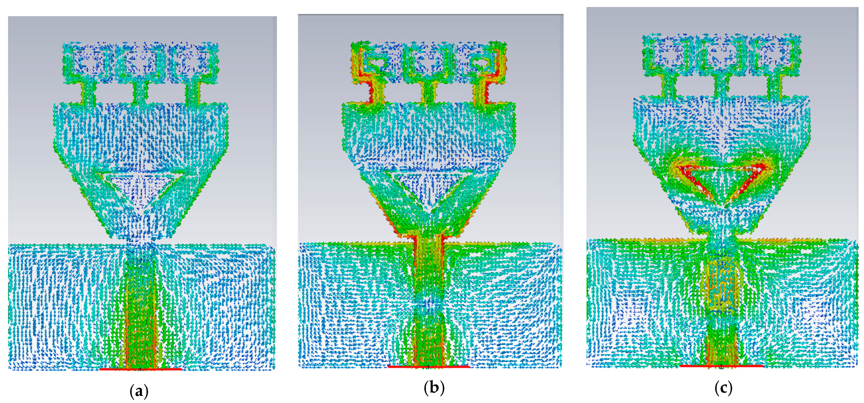
2.4. Simulated Analysis
3. Parametric Study
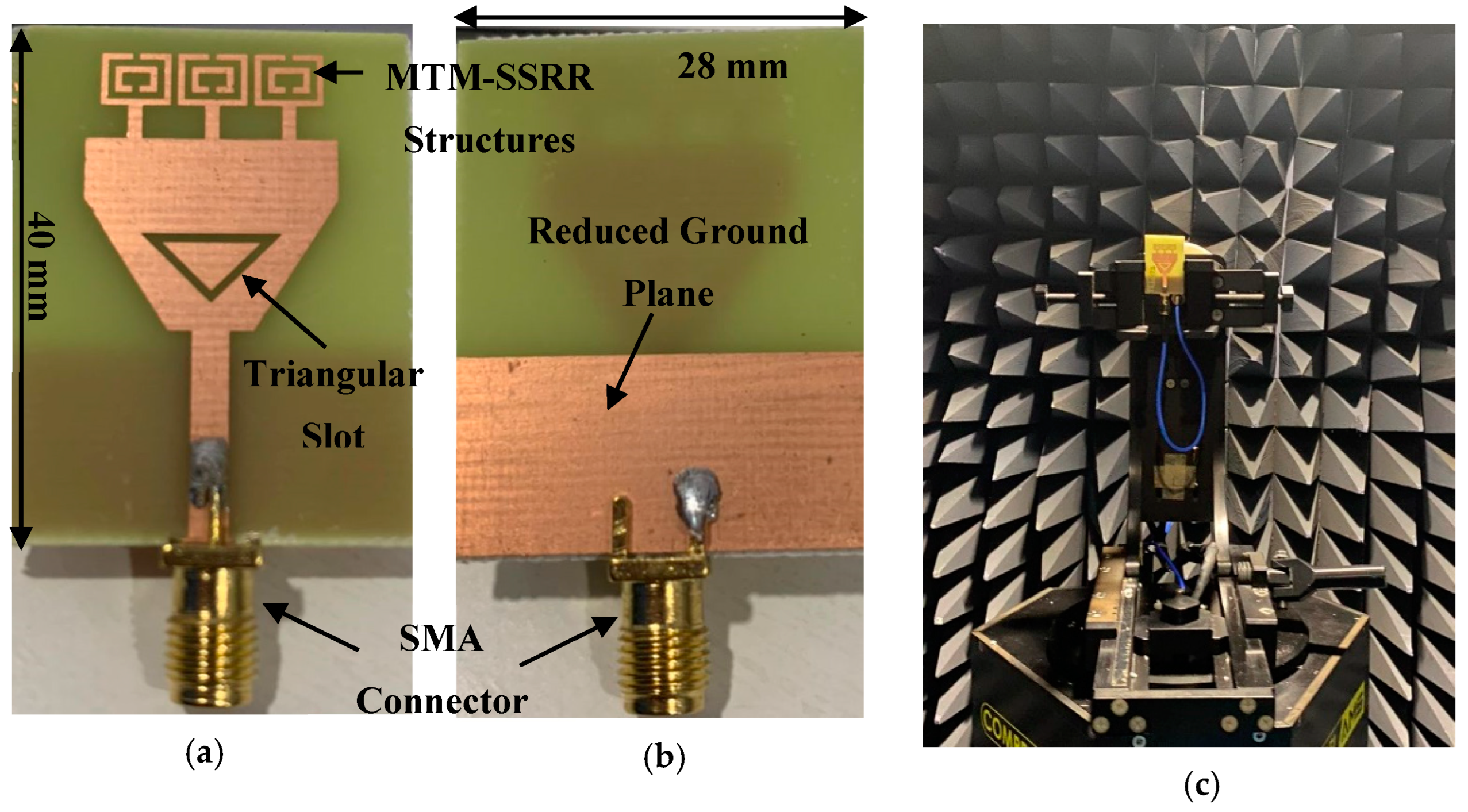
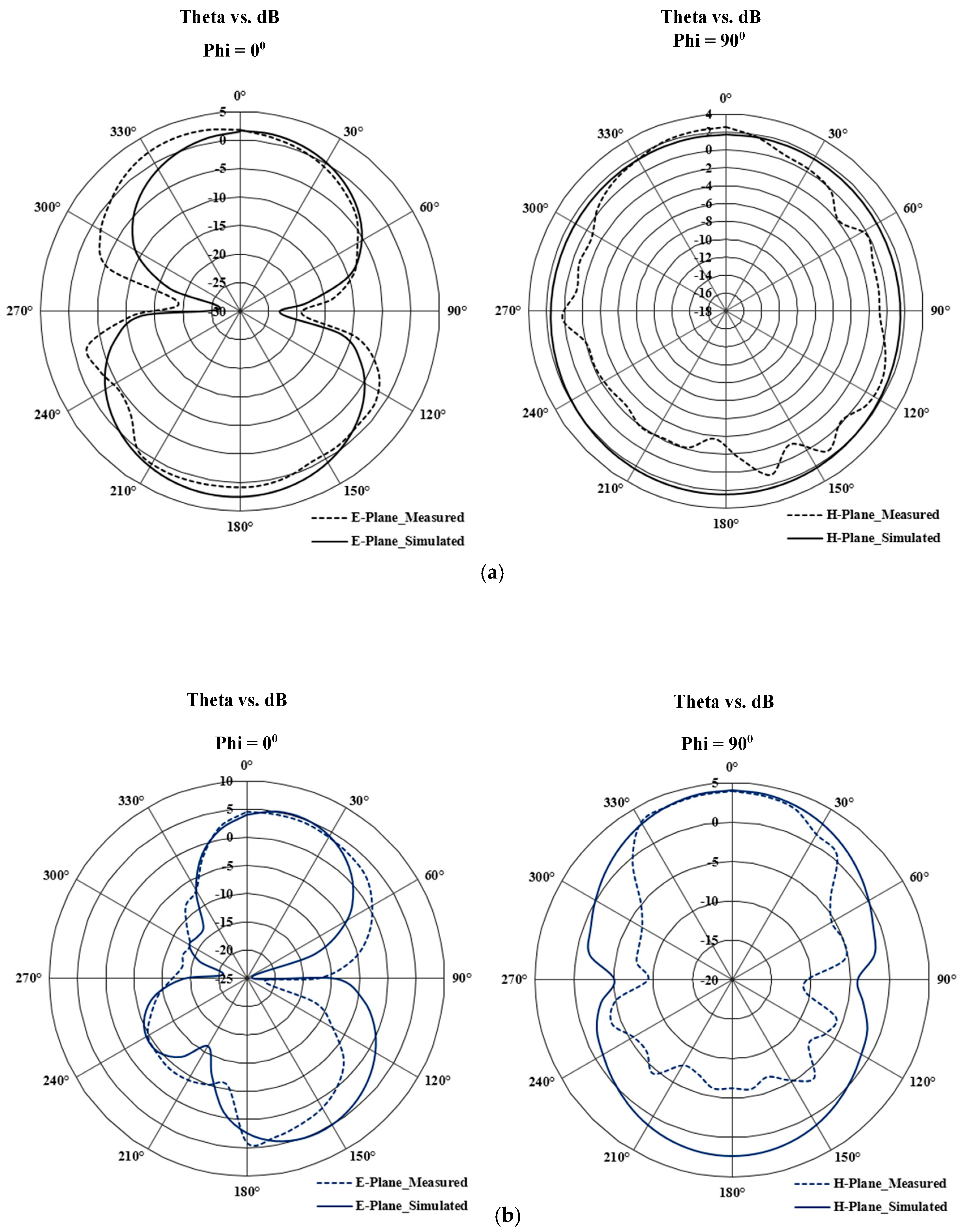
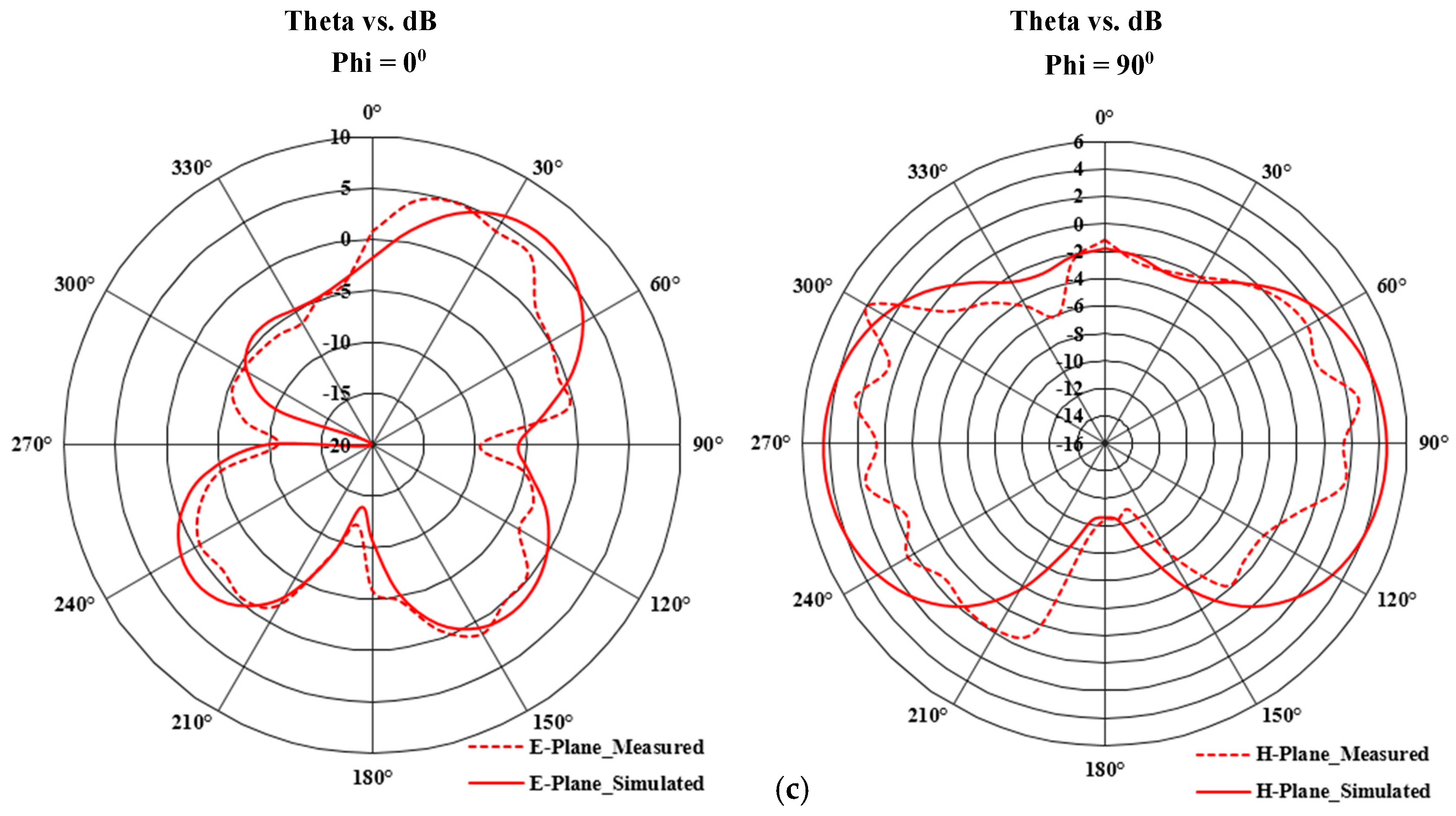
4. Results and Discussion
5. Comparative Study
6. Conclusions
Author Contributions
Funding
Institutional Review Board Statement
Informed Consent Statement
Data Availability Statement
Acknowledgments
Conflicts of Interest
References
- Liaskos, C.; Mamatas, L.; Pourdamghani, A.; Tsioliaridou, A.; Ioannidis, S.; Pitsillides, A.; Schmid, S.; Akyildiz, I.F. Software-Defined Reconfigurable Intelligent Surfaces: From Theory to End-to-End Implementation. Proc. IEEE 2022, 1–28. [Google Scholar] [CrossRef]
- Rappaport, T.S.; Xing, Y.; Kanhere, O.; Ju, S.; Madanayake, A.; Mandal, S.; Alkhateeb, A.; Trichopoulos, G.C. Wireless Communications and Applications above 100 GHz: Opportunities and Challenges for 6G and beyond. IEEE Access 2019, 7, 78729–78757. [Google Scholar] [CrossRef]
- America’s 5G Future. Available online: https://www.fcc.gov/5G (accessed on 14 July 2022).
- Shafique, K.; Khawaja, B.A.; Sabir, F.; Qazi, S.; Mustaqim, M. Internet of Things (IoT) for Next-Generation Smart Systems: A Review of Current Challenges, Future Trends and Prospects for Emerging 5G-IoT Scenarios. IEEE Access 2020, 8, 23022–23040. [Google Scholar] [CrossRef]
- Vallappil, A.K.; Rahim, M.K.A.; Khawaja, B.A.; Murad, N.A.; Mustapha, M.G. Butler Matrix Based Beamforming Networks for Phased Array Antenna Systems: A Comprehensive Review and Future Directions for 5G Applications. IEEE Access 2020, 9, 3970–3987. [Google Scholar] [CrossRef]
- Stefanini, L.; Rech, A.; Ramaccia, D.; Tomasin, S.; Toscano, A.; Moretto, F.; Bilotti, F. Multibeam Scanning Antenna System Based on Beamforming Metasurface for Fast 5G NR Initial Access. IEEE Access 2022, 10, 65982–65995. [Google Scholar] [CrossRef]
- Razzaqi, A.A.; Khawaja, B.A.; Ramzan, M.; Zafar, M.J.; Nasir, S.A.; Mustaqim, M.; Tarar, M.A.; Tauqeer, T. A triple-band antenna array for next-generation wireless and satellite-based applications. Int. J. Microw. Wirel. Technol. 2014, 8, 71–80. [Google Scholar] [CrossRef] [Green Version]
- David, R.M.; AW, M.S.; Ali, T.; Kumar, P. A Multiband Antenna Stacked with Novel Metamaterial SCSRR and CSSRR for WiMAX/WLAN Applications. Micromachines 2021, 12, 113. [Google Scholar] [CrossRef]
- Khawaja, B.A.; Tarar, M.A.; Tauqeer, T.; Amir, F.; Mustaqim, M. A 1 × 2 Triple Band Printed Antenna Array for Use in Next Generation Flying Ad-Hoc Networks (FANETs). Microw. Opt. Technol. Lett. 2016, 58, 606–610. [Google Scholar] [CrossRef]
- Ali, Q.; Shahzad, W.; Ahmad, I.; Safiq, S.; Bin, X.; Abbas, S.M.; Sun, H. Recent Developments and Challenges on Beam Steering Characteristics of Reconfigurable Transmitarray Antennas. Electronics 2022, 11, 587. [Google Scholar] [CrossRef]
- Modak, S.; Khan, T. A slotted UWB-MIMO antenna with quadruple band-notch characteristics using mushroom EBG structure. AEU Int. J. Electron. Commun. 2021, 134, 153673. [Google Scholar] [CrossRef]
- Zou, Q.; Jiang, S. A compact flexible fractal ultra-wideband antenna with band notch characteristic. Microw. Opt. Technol. Lett. 2020, 63, 895–901. [Google Scholar] [CrossRef]
- Nikolaou, S.; Abbasi, M.A.B. Design and Development of a Compact UWB Monopole Antenna with Easily-Controllable Return Loss. IEEE Trans. Antennas Propag. 2017, 65, 2063–2067. [Google Scholar] [CrossRef] [Green Version]
- Tian, M.; Yan, N.; Luo, Y.; Ma, K. A Low-Cost High-Gain Filtering Patch Antenna Using SISL Technology for 5G Application. IEEE Antennas Wirel. Propag. Lett. 2021, 20, 2270–2274. [Google Scholar] [CrossRef]
- Cai, C.-A.; Kai, K.-Y.; Liao, W.-J. A WLAN/WiFi-6E MIMO Antenna Design for Handset Devices. In Proceedings of the 2021 International Symposium on Antennas and Propagation (ISAP), Taipei, Taiwan, 19–22 October 2021. [Google Scholar] [CrossRef]
- Ullah, R.; Ullah, S.; Faisal, F.; Ullah, R.; Ben Mabrouk, I.; Al Hasan, M.J.; Kamal, B. A novel multi-band and multi-generation (2G, 3G, 4G, and 5G) 9-elements MIMO antenna system for 5G smartphone applications. Wirel. Netw. 2021, 27, 4825–4837. [Google Scholar] [CrossRef]
- El-Khamy, S.E.; Zaki, A.; Hamdy, S.; El-Khouly, A. A new fractal-like tree structure of circular patch antennas for UWB and 5G multi-band applications. Microw. Opt. Technol. Lett. 2017, 59, 2168–2174. [Google Scholar] [CrossRef]
- Abbas, A.; Hussain, N.; Jeong, M.-J.; Park, J.; Shin, K.S.; Kim, T.; Kim, N. A Rectangular Notch-Band UWB Antenna with Controllable Notched Bandwidth and Centre Frequency. Sensors 2020, 20, 777. [Google Scholar] [CrossRef] [Green Version]
- Balanis, C.A. Antenna Theory: Analysis and Design, 4th ed.; Wiley: Hoboken, NJ, USA, 2016. [Google Scholar]
- Vallappil, A.K.; Khawaja, B.A.; Rahim, M.K.A.; Iqbal, M.N.; Chattha, H.T. Metamaterial-Inspired Electrically Compact Triangular Antennas Loaded with CSRR and 3 × 3 Cross-Slots for 5G Indoor Distributed Antenna Systems. Micromachines 2022, 13, 198. [Google Scholar] [CrossRef]
- Cicchetti, R.; Miozzi, E.; Testa, O. Wideband and UWB Antennas for Wireless Applications: A Comprehensive Review. Int. J. Antennas Propag. 2017, 2017, 1–45. [Google Scholar] [CrossRef] [Green Version]
- Shafique, K.; Mustaqim, M.; Khan, B.M.; Khawaja, B. A Thin and Flexible Ultra Wideband Antenna for Wireless Body Area Networks with Reduced Ground Plane Effect. In Proceedings of the 2015 IEEE Conference on Emerging Technologies (ICET), Peshawar, Pakistan, 19–20 December 2015. [Google Scholar]
- Kumar, O.P.; Kumar, P.; Ali, T.; Kumar, P.; Vincent, S. Ultrawideband Antennas: Growth and Evolution. Micromachines 2022, 13, 60. [Google Scholar] [CrossRef]
- Mustaqim, M.; Khawaja, B.A.; Chattha, H.T.; Shafique, K.; Zafar, M.J.; Jamil, M. Ultra Wideband Antenna for Wearable Internet of Things Devices and Wireless Body Area Network Applications. Int. J. Numer. Model. Electron. Netw. Devices Fields 2019, 32, e2590. [Google Scholar] [CrossRef]
- Ganesan, I.; Iyampalam, P. A Review of Ultra-Wideband Fractal Antennas. In Proceedings of the 2018 Second International Conference on Inventive Communication and Computational Technologies (ICICCT), Coimbatore, India, 20–21 April 2018; pp. 1408–1412. [Google Scholar] [CrossRef]
- Reddy, A.P.; Muthusamy, P. A Review on UWB Metamaterial Antenna. In Innovations in Electronics and Communication Engineering. Lecture Notes in Networks and Systems; Saini, H.S., Singh, R.K., Tariq Beg, M., Sahambi, J.S., Eds.; Springer: Berlin, Germany, 2020; Volume 107. [Google Scholar] [CrossRef]
- Shome, P.P.; Khan, T.; Koul, S.K.; Antar, Y.M. Two Decades of UWB Filter Technology: Advances and Emerging Challenges in the Design of UWB Bandpass Filters. IEEE Microw. Mag. 2021, 22, 32–51. [Google Scholar] [CrossRef]
- Rahman, M.; Khan, W.T.; Imran, M. Penta-notched UWB antenna with sharp frequency edge selectivity using combination of SRR, CSRR, and DGS. AEU Int. J. Electron. Commun. 2018, 93, 116–122. [Google Scholar] [CrossRef]
- Alizadeh, F.; Ghobadi, C.; Nourinia, J.; Abdi, H.; Mohammadi, B. UWB dual-notched planar antenna by utilizing compact open meander slitted EBG structure. AEU Int. J. Electron. Commun. 2021, 136, 153715. [Google Scholar] [CrossRef]
- Kumar, G.; Singh, D.; Kumar, R. A planar CPW fed UWB antenna with dual rectangular notch band characteristics incorporating U-slot, SRRs, and EBGs. Int. J. RF Microw. Comput. Eng. 2021, 31, e22676. [Google Scholar] [CrossRef]
- Rahman, S.U.; Cao, Q.; Li, Y.; Gil, I.; Yi, W. Design of tri-notched UWB antenna based on elliptical and circular ring resonators. Int. J. RF Microw. Comput. Eng. 2018, 29, e21648. [Google Scholar] [CrossRef]
- Abbas, A.; Hussain, N.; Lee, J.; Park, S.G.; Kim, N. Triple Rectangular Notch UWB Antenna Using EBG and SRR. IEEE Access 2020, 9, 2508–2515. [Google Scholar] [CrossRef]
- Chakraborty, M.; Pal, S.; Chattoraj, N. Quad notch UWB antenna using combination of slots and split-ring resonator. Int. J. RF Microw. Comput. Eng. 2019, 30, e22086. [Google Scholar] [CrossRef]
- Veselago, V.; Braginsky, L.; Shklover, V.; Hafner, C. Negative Refractive Index Materials. J. Comput. Theor. Nanosci. 2006, 3, 189–218. [Google Scholar] [CrossRef]
- Siddiqui, J.Y.; Saha, C.; Antar, Y.M.M. Compact Dual-SRR-Loaded UWB Monopole Antenna with Dual Frequency and Wideband Notch Characteristics. IEEE Antennas Wirel. Propag. Lett. 2014, 14, 100–103. [Google Scholar] [CrossRef]


| Parameter | Dimension (mm) |
|---|---|
| E | 40 mm |
| F | 28 mm |
| G | 14 mm |
| H | 2.6 mm |
| W | 5 mm |
| S | 0.5 mm |
| X | 0.5 mm |
| Y | 1 mm |
| Z | 2.5 mm |
| P | 6 mm |
| R | 11 mm |
| T | 0.9 mm |
| Q | 13 mm |
| Step No. | No of Operational Bands | Operational Bands Coverage (GHz) | No. of Rejection Bands | Rejection Bands Coverage (GHz) |
|---|---|---|---|---|
| 1 | 1 | 3–12 | - | - |
| 2 | 2 | 3–5.7, 8.3–12 | 1 | 5.7–8.3 |
| 3 | 3 | 3–4.2, 5.45–6.77, 8.7–12 | 2 | 4.2–5.45, 6.77–8.7 |
| Parameter | Operational Bands Coverage (GHz) | Rejection Bands Coverage (GHz) |
|---|---|---|
| S = 0.65 mm | 3–4.2, 5.45–6.72, 9.1–12 | 4.2–5.45, 6.72–9.1 |
| S = 0.9 mm | 3–4.2, 5.45–6.77, 8.7–12 | 4.2–5.45, 6.77–8.7 |
| S = 1.15 mm | 3–4.2, 5.45–6.73, 8.5–12 | 4.2–5.45, 6.73–8.5 |
| t = 0.4 mm | 3–4.2, 5.4–6.5, 8.5–12 | 4.2–5.4, 6.5–8.5 |
| t = 0.5 mm | 3–4.2, 5.45–6.77, 8.7–12 | 4.2–5.45, 6.77–8.7 |
| t = 0.6 mm | 3–4.2, 5.45–6.98, 8.7–12 | 4.2–5.45, 6.98–8.7 |
| Ref No./Year | Size (mm3) | Substrate (εr) | No. of Notch Band | Coverage of Bands (GHz) | Controllable Notch-Bandwidth | Controllable Notch Frequency | Technique | Complexity | Operational Bandwidth (GHz) |
|---|---|---|---|---|---|---|---|---|---|
| [12]/2020 | 20.5 × 13.9 × 0.012 | 3.5 | 1 | 7.9–8.4 | No | No | Complimentary-SRR (CSRR) | High | 3.6–19.08 |
| [18]/2020 | 16 × 25 × 1.52 | 2.17 | 1 | 5–6 | Yes | Yes | EBG | Low | 3.1–12.5 |
| [29]/2021 | 25 × 35 × 1.6 | 4.3 | 2 | 3.11–4.01, 5.15–5.98 | No | No | Open meander slitted EBG structure | Low | 2.63–13 |
| [31]/2018 | 36 × 34 × 1 | 2.65 | 3 | 3.97–4.48, 5.79–6.57, 7.30–7.60 | Only one lower notch band controllable | Only one notch frequency controllable | Elliptical and circular ring resonators | High/Active elements are there | 3.1–10.6 |
| [32]/2021 | 20 × 26 × 1.52 | 2.17 | 3 | 3.4–3.95, 5.15–5.82, 7.25–7.75 | No | No | EBG and SRR | High | 3.1–11.8 |
| [35]/2014 | 50 × 50 × 1.575 | 2.33 | 2 | 5.15–5.82, 6.2–6.9 GHz | No | No | SRR | Low | 3.1–10 |
| This work/2022 | 28 × 40 × 1.6 | 4.3 | 2 | 4.17–5.33, 6.5–8.9 | Yes | Yes | SSRR and Triangular slot | Low | 3–12 |
Publisher’s Note: MDPI stays neutral with regard to jurisdictional claims in published maps and institutional affiliations. |
© 2022 by the authors. Licensee MDPI, Basel, Switzerland. This article is an open access article distributed under the terms and conditions of the Creative Commons Attribution (CC BY) license (https://creativecommons.org/licenses/by/4.0/).
Share and Cite
Vallappil, A.K.; Khawaja, B.A.; Rahim, M.K.A.; Iqbal, M.N.; Chattha, H.T.; Ali, M.F.b.M. A Compact Triple-Band UWB Inverted Triangular Antenna with Dual-Notch Band Characteristics Using SSRR Metamaterial Structure for Use in Next-Generation Wireless Systems. Fractal Fract. 2022, 6, 422. https://doi.org/10.3390/fractalfract6080422
Vallappil AK, Khawaja BA, Rahim MKA, Iqbal MN, Chattha HT, Ali MFbM. A Compact Triple-Band UWB Inverted Triangular Antenna with Dual-Notch Band Characteristics Using SSRR Metamaterial Structure for Use in Next-Generation Wireless Systems. Fractal and Fractional. 2022; 6(8):422. https://doi.org/10.3390/fractalfract6080422
Chicago/Turabian StyleVallappil, Arshad Karimbu, Bilal A. Khawaja, Mohamad Kamal A. Rahim, Muhammad Naeem Iqbal, Hassan T. Chattha, and Mohamad Fakrie bin Mohamad Ali. 2022. "A Compact Triple-Band UWB Inverted Triangular Antenna with Dual-Notch Band Characteristics Using SSRR Metamaterial Structure for Use in Next-Generation Wireless Systems" Fractal and Fractional 6, no. 8: 422. https://doi.org/10.3390/fractalfract6080422
APA StyleVallappil, A. K., Khawaja, B. A., Rahim, M. K. A., Iqbal, M. N., Chattha, H. T., & Ali, M. F. b. M. (2022). A Compact Triple-Band UWB Inverted Triangular Antenna with Dual-Notch Band Characteristics Using SSRR Metamaterial Structure for Use in Next-Generation Wireless Systems. Fractal and Fractional, 6(8), 422. https://doi.org/10.3390/fractalfract6080422