Article

Fractal Analysis for Wave Propagation in Combustion–Explosion Fracturing Shale Reservoir

1
State Key Laboratory for Geomechanics & Deep Underground Engineering, School of Mechanics and Civil Engineering, China University of Mining and Technology, Xuzhou 221116, China
2
YunLong Lake Laboratory of Deep Underground Science and Engineering, Xuzhou 221116, China
3
Key Laboratory for Urban Underground Engineering of the Education Ministry, Beijing Jiaotong University, Beijing 100044, China
4
School of Safety Engineering, China University of Mining and Technology, Xuzhou 221116, China
*
Authors to whom correspondence should be addressed.
Fractal Fract. 2022, 6(11), 632; https://doi.org/10.3390/fractalfract6110632
Submission received: 18 September 2022 / Revised: 15 October 2022 / Accepted: 28 October 2022 / Published: 30 October 2022
(This article belongs to the Section Engineering)

Abstract

:
The in-situ combustion–explosion fracturing technology in shale reservoirs can promote continuous fracture expansion with a radial detonation wave first converging into a shock wave and then decaying into an elastic wave. The transformation scale of the shale reservoir is determined by the range of wave propagation during combustion–explosion. As wave propagation paths are usually tortuous and fractal, the previous integer wave models are not competent to describe the wave propagation and estimate the impact range of the combustion–explosion fracturing process. This study develops two fractional wave propagation models and seeks analytical solutions. Firstly, a novel fractional wave model of rotation angle is proposed to describe the process of detonation waves converting into shock waves in a bifurcated structure. The radial displacement gradient of the detonation wave is represented by the internal expansion and rotation deformation of the shale. Secondly, another fractional wave propagation model of radial displacement is proposed to show the process of a shock wave decaying into an elastic wave. Thirdly, the proposed models are analytically solved through the fractional variable separation method and variational iteration method, respectively. Analytical solutions for rotation angle and radial displacement with fractal time and space are obtained. Finally, the impacts of the branching parameter of the detonation wave converge bifurcation system, aggregation order of detonation compression wave, and different types of explosives on the rotation angle of the shock wave are investigated. The propagation mechanism of the primary wave (P-wave) with time and space is analyzed. The analytical solutions can well describe the wave propagation process in fractured shales. The proposed fractional wave propagation models can promote the research of wave propagation in the combustion–explosion fracturing process of shale reservoirs.

1. Introduction

Shale gas in matrix pores is still difficult to extract by traditional hydraulic fracturing. New shale gas development technologies must be explored [1] for wider fracture works. The in-situ combustion–explosion technology is a transformative and disruptive technology in shale gas production [2,3]. It is a complex dynamic process of shale fracturing during in-situ combustion–explosion of methane [4,5]. The shale is damaged under the action of the explosion shock wave, stress wave, and explosion gas [6,7]. Complex fracture networks develop in the shale reservoir, and the permeability of the shale reservoir increases dramatically [8]. Firstly, the blast stress wave and rapid expansion of the blasting gas produce fractures in the formation, then a new micro-fracture network connects and communicates more natural fractures. Due to the extremely low viscosity and high permeability, the explosion gas is easier to enter the micro-pore structure of the rock. Moreover, the fracture network generated by high pore pressure is dense and complex [9], with the characteristics of a large fracturing range and small fracture pressure. As mentioned above, a fracture network with high density and high connectivity will formulate with the interaction between pores, bedding fractures, and artificial fractures in the shale. However, there is a lack of research and prediction on the extent of fracture network propagation under combustion–explosion. And the formation of a fracture network is determined by the propagation distance of the detonation wave. Therefore, it is necessary to study the wave propagation distance under in-situ combustion–explosion conditions.
At the moment of explosion, an air shock wave is formed under high temperature and high pressure at the combustion–explosion area and immediately acts on the shale reservoir [9], resulting in a strong impact compression effect by the supersonic propagation of the shock wave. Thus, the shale around the combustion–explosion area is extremely destroyed to form a crushing zone. It is generally considered that the radius of the crushing zone is 2 to 3 times the blast hole. Although this range is small, it consumes most of the energy of shock waves. Moreover, the shale permeability is reduced due to the limited effective fracture generation and general compaction.
The shock wave attenuates into an elastic stress wave at the interface of the crushing zone at the moment of combustion–explosion, and the compressive stress wave continues to propagate along the radial direction in the rock [10,11]. After the stress wave passes through, the rock is subjected to radial compression and tangential tension. Because of the weak tensile strength of the rock itself, it produces radial cracks under the action of tensile stress. With the constant propagation of the combustion–explosion stress wave, stress waves decay into the elastic wave propagation and enter the elastic vibration area in the rock mass. Although the elastic waves cannot damage the rock, vibration energy can cause the development of the rock matrix pores and fractures and disturb the adjacent parts during the shale mass movement, resulting in the propagation of fractures and the enhancement of permeability.
The impact time of the shock wave is short, but the action time of explosive gas is long. The stress wave caused by the expansion of explosive gas promotes the development of a fracture. Methane explodes into a gas of high temperature and high pressure and causes rock failure. The radial displacement of rock particles is caused by the expansion force of detonation gas. Since the distance between the detonation point and the free surface is different in each direction, the resistance of particle displacement is different. The resistance is the least in the direction of the least resistance line, and the displacement velocity of the rock particle is the highest. The shear stress in the rock is caused by the neighboring rock particles moving at different speeds. Once the shear stress is greater than the shear strength of the rock, the rock will undergo shear failure. Subsequently, explosive gas penetrates the fracture and further expands the fracture formed by stress waves under the action of high pore pressure. The near blasting zone is the fracture expansion zone driven by explosive gas, while the middle and far blasting zone is the micro-fracture expansion zone driven by the explosive gas pressure field, which plays an important role in enhancing and improving formation permeability and expanding connectivity.
To sum up, the fracture propagation of rock under an explosion load is mainly determined by the comminution failure caused by the shock wave, the dynamic fracture propagation caused by combustion–explosion stress wave, and the quasi-static fracture propagation caused by explosive gas. The final combustion–explosion range is determined by the rotational destruction range of the detonation wave, shock wave, and the P-wave propagation distance in the elastic wave stage. To enhance shale permeability, it is necessary to form a wider range of fracture networks rather than a large compaction zone. Therefore, the purpose of the in-situ combustion–explosion technology is to reduce the comminution damage and extend the fracture propagation time and the fracture propagation area as much as possible.
As shown in Figure 1, the structure of the shale reservoir is abnormally complicated under combustion–explosion [9]. There are large amounts of pores, fractures, and crushed shale fragments in the shale skeleton of different sizes and shapes [10]. In the previous study of gas flow in fractured shale reservoirs, the migration and transmission of matter and energy in shale reservoirs are mostly cared about by ignoring the specific structure of shale or only described with a few general structural parameters. The fundamental reason is that the complexity of the structure of shale itself is difficult to be accurately described with mathematical language.
How these anomalous shale structures and properties under the conditions of combustion–explosion affect wave propagation is still unclear. Theoretical and numerical simulation studies have been carried out for wave propagation in different materials [12,13]. However, unlike previous studies, one important task for wave propagation in the process of combustion–explosion is to establish a mathematical model along the real path [14,15,16,17]. The model should well consider the heterogeneous pores and tortuous fractures in the real stratigraphic structure of the shale reservoir, especially overlaying the effect of combustion–explosion. Fractal geometry can describe the fine structure of a porous shale reservoir. The theory of local fractional derivatives has also been successfully applied to many problems in fluid mechanics [18] and others [19,20]. And the fractal traveling-wave transformation was introduced to solve the local fractional models [21]. Some wave equations have been proposed so far, such as simple wave equations on the cantor sets, local damped wave equations, and local fractional diffusion wave equations [15,16]. However, as in-situ combustion–explosion is an original technique, the wave propagation model under this condition has not been established and analyzed yet.
This paper is organized as follows. First, two novel local fractional wave propagation models are proposed by replacing the derivatives of an integer order with fractional order based on classical wave equations. The models describe the rotation angle from the detonation wave stage to the shock wave stage and the P-wave displacement at the elastic wave stage, respectively. Second, the two models are solved through the separation of variables method and variational iteration method, respectively. The fractal analytical solutions for rotation angle and P-wave displacement are obtained, respectively. Then, the impacts of the branching parameter of the detonation wave converge bifurcation system, aggregation order of detonation compression wave, and different types of explosives on the rotation angle of the shock wave are investigated. Finally, the conclusions are drawn based on these studies.

2. Transformation Mechanism of Local Rotational Failure from Detonation Wave Stage to Shock Wave Stage

Before any further development, the following assumptions were made:
(a)
The fractured rock is a heterogeneous, anisotropic, rigorous, porous continuum;
(b)
The wave flows in the same plane, and the density and viscosity of the fluid are independent of temperature;
(c)
The shock front of a plane blasting wave is a strong discontinuity, and the chemical reaction is instantaneous. The chemical reaction region is so thin that it can be treated as a mathematical plane;
(d)
The strong discontinuity is stable, and no dissipative effects, such as viscosity and heat conduction, happen during its propagation.

2.1. Governing Equation of Rotation Angle

In the process of the explosion, due to the extremely frequent collision of gas molecules, it is impossible to identify the individual collision of a molecule, though it can only determine the collective action of a large number of molecules. Therefore, gas dynamics does not study the microscopic movement of individual gas molecules but only pays attention to the macroscopic movement of gas microclusters composed of many molecules. Therefore, when the velocity of a fluid particle or a gas particle is referred to, it stands for the velocity of the whole microclusters.
The shock wave can be seen as the superposition of an infinite number of weak compression waves. And local rotation is the main mechanism of medium destruction or damage [21,22]. With the radial propagation of the detonation wave, the peak value of the local rotation angle decreases from θ 0 that at the end of detonation. The deformation gradient is composed of two parts: the deformation matrix and the rotation matrix. The deformation gradient in the plane coordinate system can be described as follows:
F j i = | 1 0 0 1 + u r | | cos θ sin θ sin θ cos θ |
where F j i is the deformation gradient in the plane coordinate system, u is the deformation of the wave, r is the displacement, θ is the local rotation angle.
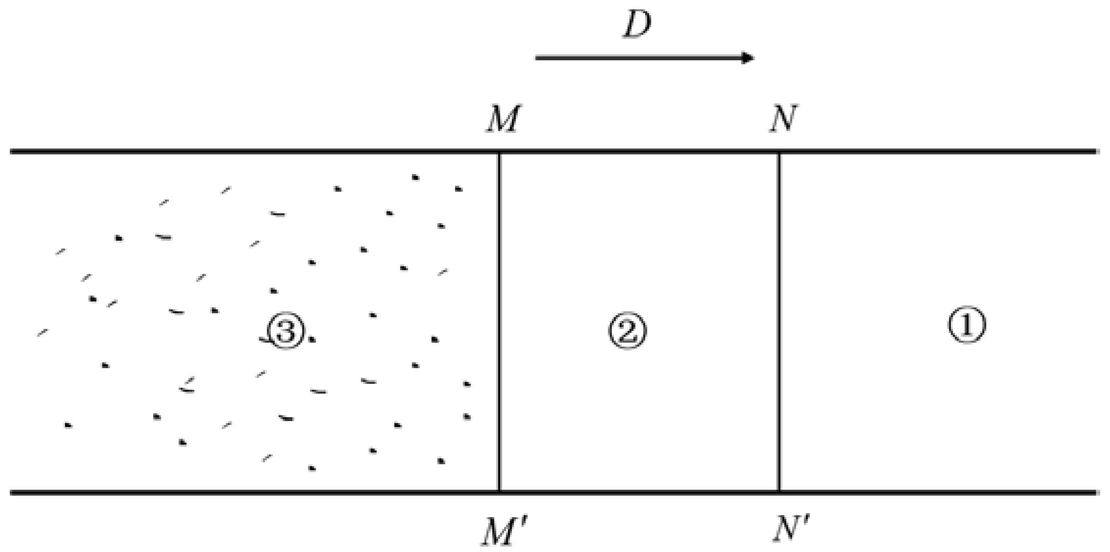
It was found that the original continuous flow may form a discontinuous surface when mathematician Riemann analyzed the unsteady movement of the fluid in the pipeline. When the shock wave passes, the state of the shale changes abruptly. The chemical reaction of detonation is completed instantaneously on an infinite thin discontinuity plane, and the original explosive is transformed into the product of the detonation reaction instantaneously. The explosives immediately initiate high-speed chemical reactions due to their strong impact effect, form detonation products with high temperature and pressure, and release a large amount of chemical reaction heat energy. The energy is used to support the detonation wave to impact the next layer of explosive compression. Thus, the detonation wave can propagate continuously and efficiently. As shown in Figure 2, the chemical reaction is completed, and detonation products are formed at the end section of the reaction zone. It is called the C–J plane [23]. In the combustion–explosion process, the leading shock wave and the following chemical reaction zone of high speed constitute a complete detonation front, which propagates at the same detonation wave velocity v C J and separates the original explosive from the final product of detonation.
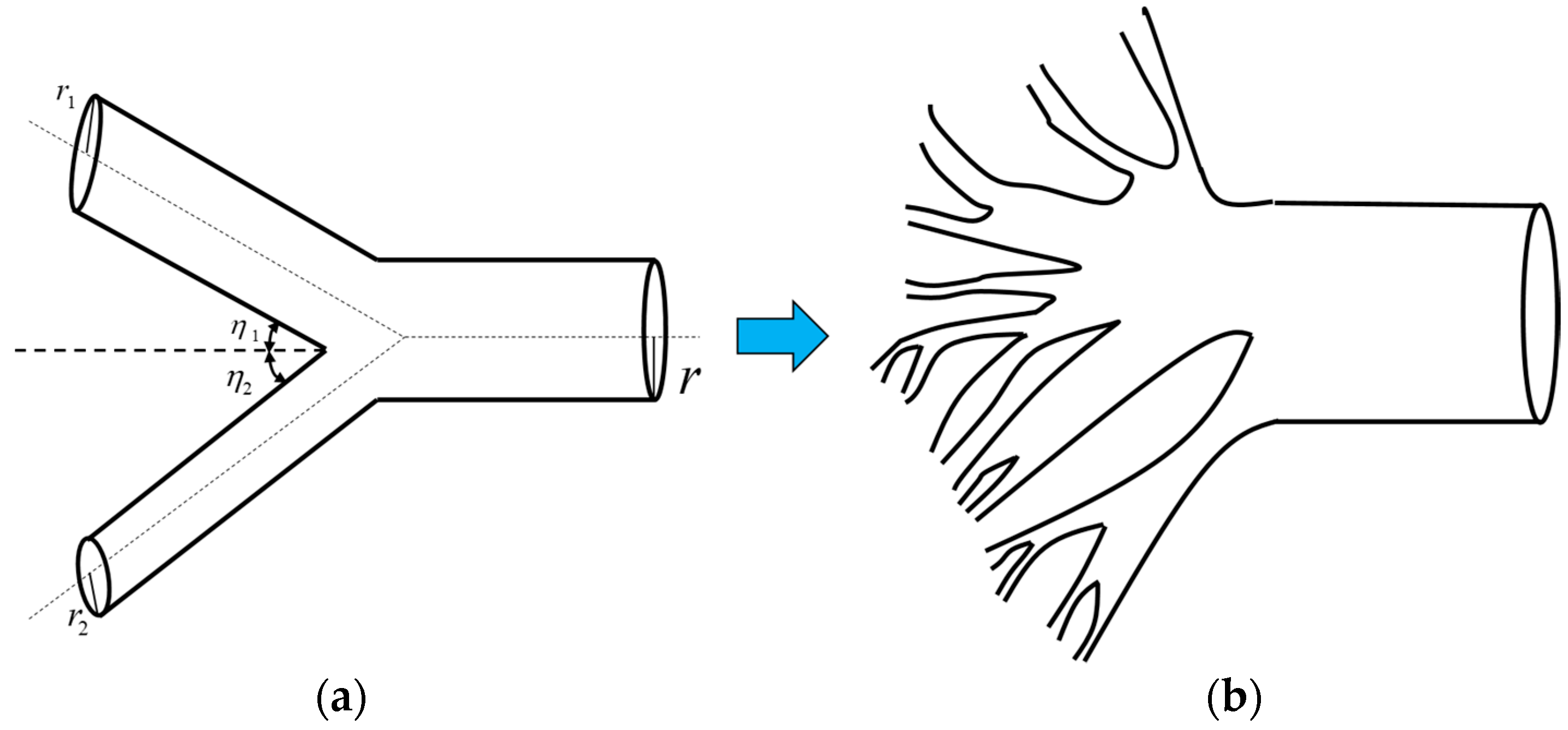
However, a shock wave is formed by the superposition of compression wave from quantitative change to qualitative change, and their properties are fundamentally different. To describe the converging process of compression waves, the propagation path of waves can be considered as a typical bifurcation system inside an intermittent shale reservoir. As shown in Figure 3b, it is assumed that the compression wave generated by combustion and explosion of the shale reservoir converges into a shock wave after m-order acceleration. To simplify the calculation, assume that the bifurcation structure is symmetric (see Figure 3a), namely:
r 1 = r 2 , η 1 = η 2
A branching parameter X is then introduced based on Murray’s law and defined as [24]
X = r 0 3 2 r 1 3
where r 1 , r 2 are the second capillary radius of the bifurcate tree, respectively. η 1 , η 2 are the angles between the superior binary tree and the subordinate binary tree, respectively.
According to the energy conservation law and Murray’s law, the change of the branching parameter X can deduce the relationship of average wave velocities between the 0-th bifurcated pipe and the m-th pipe during the steady propagation of C–J detonation.
v C J = ( X 2 / 2 ) m / 3 v C J , 0
where v C J , 0 is the compression wave velocity of the 0-th pipe, v C J is the shock wave velocity of the m-th pipe after the superposition of the compression wave.
By analyzing the dynamics of the reaction zone, it is found that if the radius of the detonation wave surface curvature is much larger than the width of the chemical reaction zone, the velocity of detonation wave excitation is only the function of wave surface curvature [25,26].
v n = v n ( κ )
where v n is the normal velocity of the detonation wave, κ is the mean curvature of the wave surface.
Under a constant chemical reaction rate, the linear relationship between shock velocity and wave surface curvature is deduced [21].
v n = v C J ( 1 b κ )
where v n is the normal velocity of the detonation wave, v C J is the CJ velocity, b is a constant related to the nature of the explosive, κ is the mean curvature of the wave surface.
Equation (6) can be translated into:
κ = 1 v n v C J b
The plane curvature κ p is:
κ p = 2 κ = 2 ( 1 v n v C J ) b
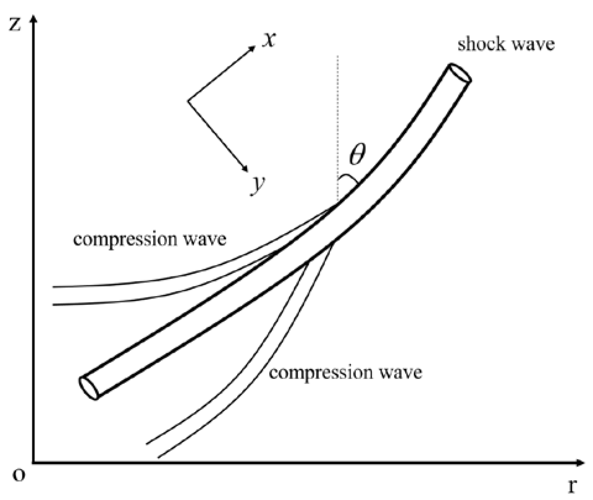
Through the interaction between the detonation wave and the shale reservoir, the intersection angle between the normal direction of the detonation wave and the interface can be calculated. The experimental results show that the normal direction of the detonation wave surface is a fixed angle with the medium interface [21]. Thus, rock failure by shock wave is caused by rotation and shearing, which is related to the shale rock surface and angle (see Figure 4).
Substituting Equation (4) into Equation (8) yields:
κ p = 2 ( 1 v n ( X 2 / 2 ) m / 3 v C J , 0 ) b
As shown in Figure 4, to describe the propagation of the shock waves, the orthogonal coordinate system is introduced. The x curve is the position of the curved shock front at different moments. The y curve is a ray orthogonal to the wave surface. Since the x curve stands for the location of shock waves at a different moment, the parameter x is set as:
x = t
The motion equation of the shock wave can be obtained by coordinate transformation:
{ α θ x α = - 1 h α v n y α α θ y α = 1 v n α h x α
where α ( ) / x α is the local fractional derivative with respect to x. α ( ) / y α is the local fractional derivative with respect to y. α is the local fractional order, and 0 < α 1 , h is a Lame coefficient in curvilinear coordinates in mathematics, and it is also a function between the velocity of shock wave and area A, namely h = h ( A ) .
Two adjacent y curves form a ray tube, and the value of arc length is defined as:
d α ξ = h d α y
where ξ is the arc length between adjacent curves on the same shock wave surface.
The mean curvature can be expressed by:
κ p = α θ ξ α = 1 h α θ y α
Combining Equations (11) and (13) with Equation (12) yields after the reference [21]
α v n x α = 1 κ p 1 h α y α ( 1 h α θ y α )
Substituting Equation (9) into Equation (14) yields:
α θ x α = b ( X 2 / 2 ) m / 3 v C J , 0 2 1 h α y α ( 1 h α θ y α )
Transforming the coordinate from ( x , y ) to ( t , ξ ) yields:
{ α θ ξ α = 1 h α θ y α α θ t α = α θ x α
Integrating Equation (16) with Equation (15) yields the detonation wave equation on the Cantor sets:
α θ t α = b ( X 2 / 2 ) m / 3 v C J , 0 2 2 α θ ξ 2 α
with the initial conditions:
t 0 = 0 , θ 0 = 0
and the boundary conditions:
r = R , θ = θ b
where R is the radius of detonation wave area, θ b is the angle between the wave surface and Z axis at the interface.

2.2. Analytical Solutions of Rotation Angle

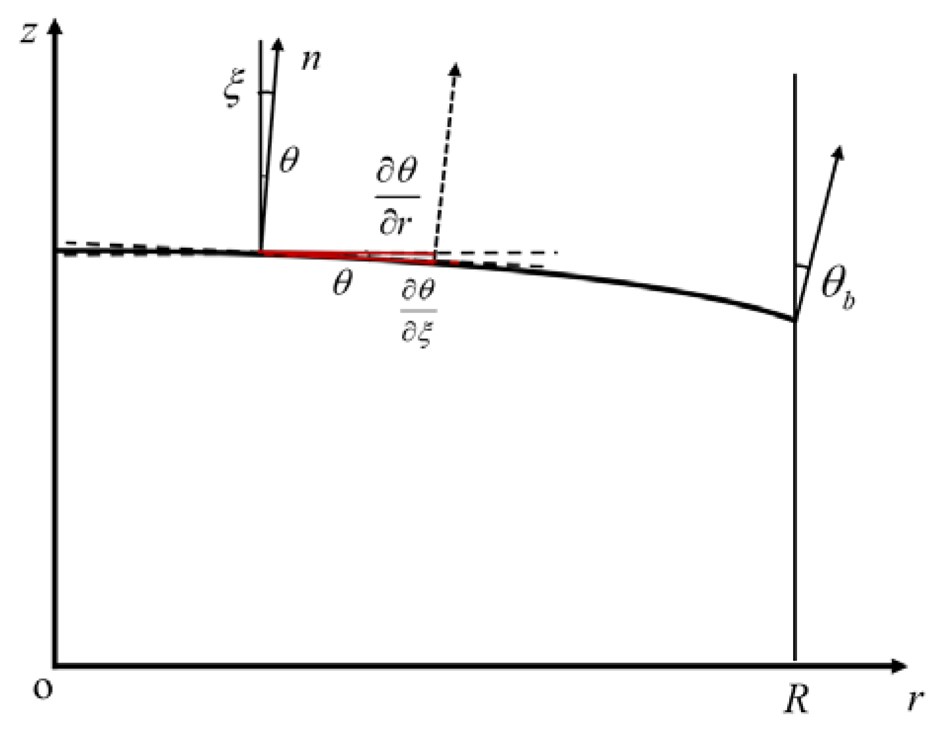
The relationship between rotation angle and detonation wave surface is shown in Figure 5.
It can be found that:
α θ ξ α = cos α ( θ α ) α θ r α
2 α θ ξ 2 α = - sin α ( θ α ) α θ r α + cos α ( θ α ) 2 α θ r 2 α
Assume that the θ b is a small value [21], then:
sin α ( θ α ) 0 , cos α ( θ α ) 1
Substituting Equations (21) and (22) into Equation (17) yields:
α θ t α = b ( X 2 / 2 ) m / 3 v C J , 0 2 2 α θ r 2 α
Set:
θ ( r , t ) = ϕ ( r ) T ( t )
Equation (17) can be translated into:
ϕ ( 2 α ) + λ 2 α ϕ = 0
T ( α ) + λ 2 α b ( X 2 / 2 ) m / 3 v C J , 0 2 T = 0
where λ is the eigenvalue of the eigenvalue problem. With the boundary conditions:
ϕ ( 0 ) = ϕ ( α ) ( R ) = 0
The solution of Equation (25) can be obtained as follows [19]
λ n α = ( n π R ) α ( n = 0 , 1 , 2 , )
ϕ n ( ξ ) = sin α n α ( π r R ) α ( n = 0 , 1 , 2 , )
Substituting Equation (28) into Equation (26) yields:
T ( α ) + ( n π R ) 2 α · b ( X 2 / 2 ) n / 3 v C J , 0 2 · T = 0
The solution of T ( t ) is:
T n ( t ) = E α ( ( n π R ) 2 α b ( X 2 / 2 ) n / 3 v C J , 0 2 t α )
where:
E α ( t α ) = i = 0 t α i Γ ( 1 + α i )
Therefore, the solution of θ ( r , t ) is:
θ ( r , t ) = n = 1 θ n ( r , t ) = n = 1 E α ( ( n π R ) 2 α b ( X 2 / 2 ) n / 3 v C J , 0 2 t α ) sin α n α ( π r R ) α
where:
sin α ( t α ) = i = 0 ( 1 ) i t α ( 2 i + 1 ) Γ ( 1 + ( 2 i + 1 ) α )
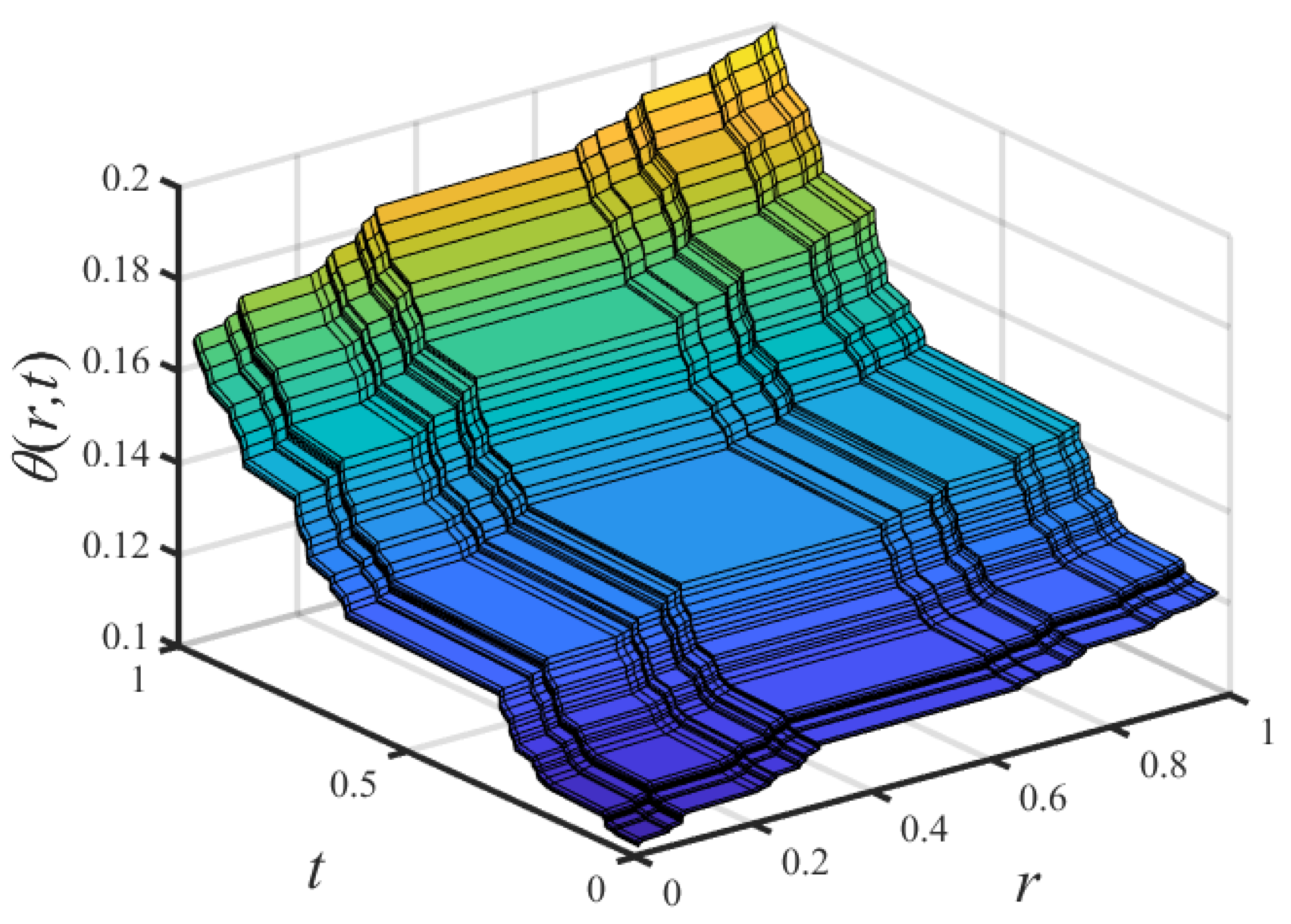
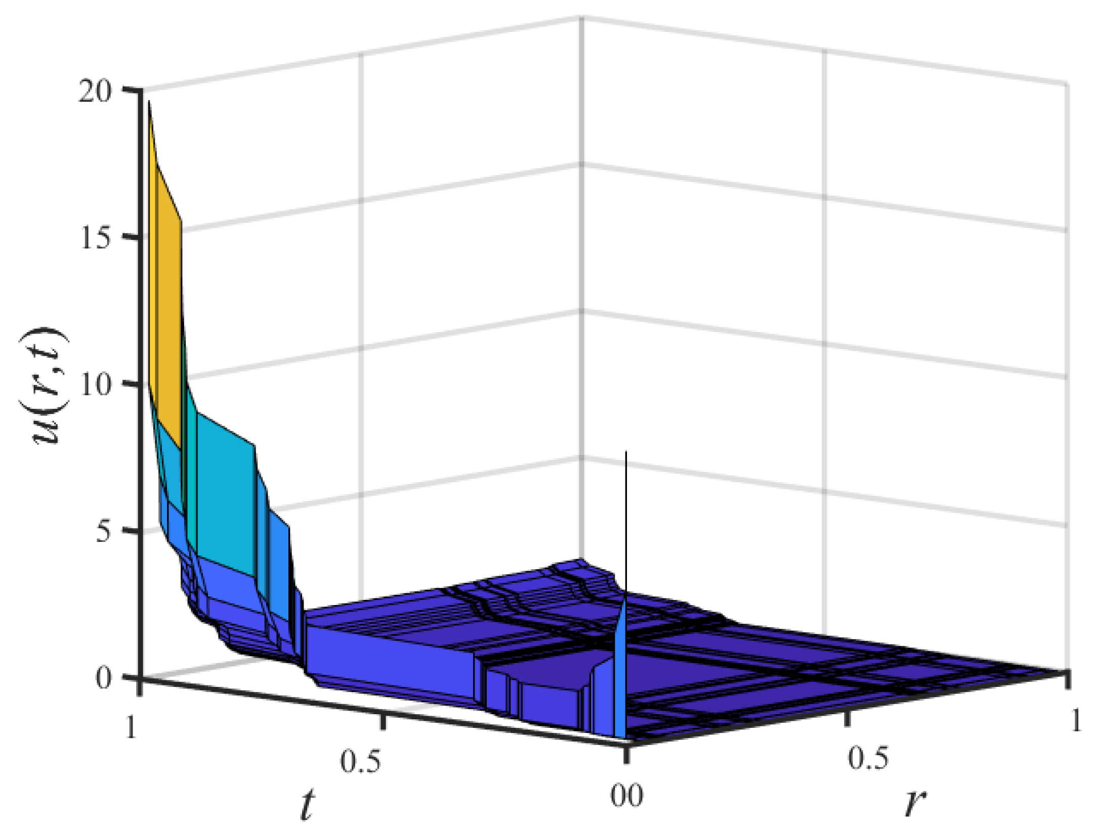
and its plot is shown in Figure 6.

2.3. Discussion

The above model describes the wave propagation process of local rotational failure from the detonation wave stage to the shock wave stage, including the convergence of compression waves, rotation of shock wave, and fracture bifurcation system. Table 1 lists the computational parameters used in analytical solutions. These parameters are taken from related literature [21,27]. The obtained analytical solution is discussed in the following data.

2.3.1. General Change of Rotation Angle

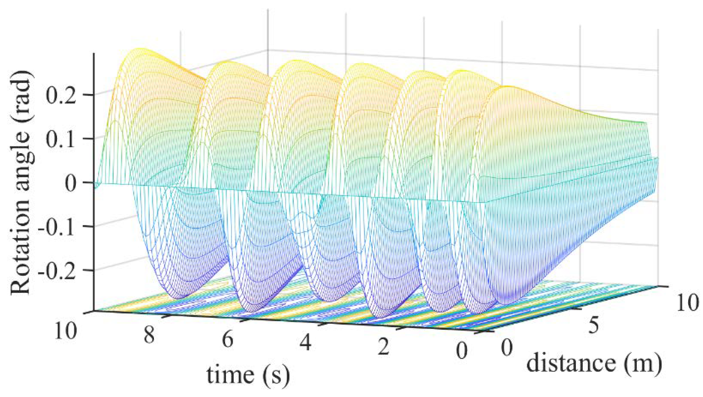
Figure 7 describes the change of rotation angle with time and distance. It can be seen that the rotation angle of the shock wave fluctuates, and the value of the shock wave peak increases over time. The rotation angle between the detonation wave and the normal phase direction at the moment of explosion is 0. Taking the detonation center point as an example, with the continuous occurrence of an explosion, the donation compression wave accumulates, making the rotation angle of the wave increase continuously. In addition, the rotation decreases as the distance increases. It shows that the effect of the detonation wave is gradually weakened and transferred to other forms of the wave with the increase in the explosion distance.

2.3.2. Sensitive Analysis of Branching Parameter

The branching parameter X is introduced to represent the cube ratio of channel width between the upper and lower levels based on Murray’s law. This section will study the impact of the branching parameter on the rotation angle.
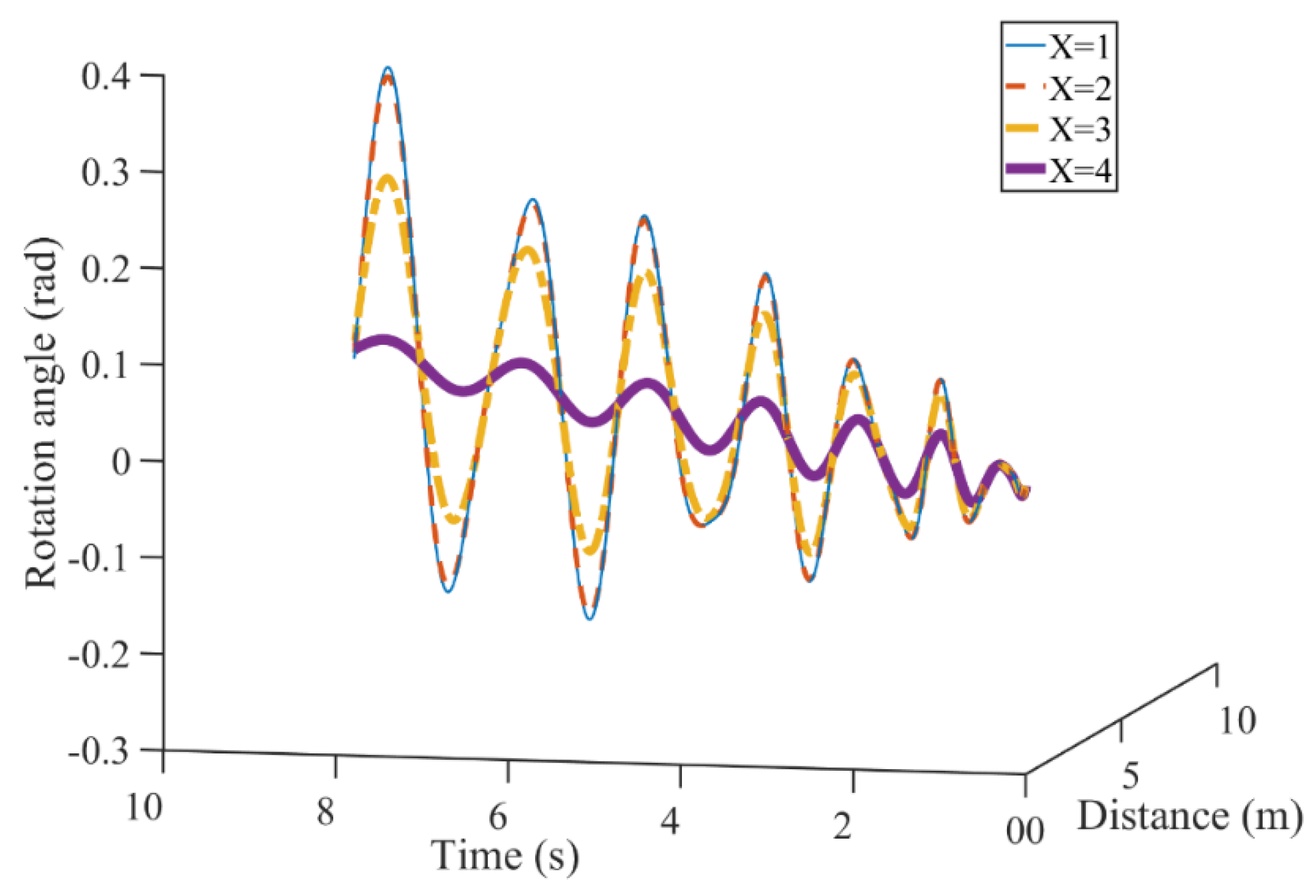
The branching parameter is 1, 2, 3, and 4, respectively. The branching parameter is taken from the data obtained by Yu et al. [24]. Figure 8 presents the volatility of the rotation angle with time and distance. The amplitudes of the four curves all increase in the first 10 s of combustion–explosion. Little difference is observed between X = 1 and X = 2. However, a larger difference is observed for the rotation angle of X = 3 and X = 4. The rotation angle at the 8th s is 0.42 rad, 0.4 rad, 0.28 rad, and 0.12 rad, respectively. With the value of the branching parameter increasing, the amplitude of the rotation angle goes down faster in the shock wave stage. It reaches a lower rotation angle in the explosion tail. This implies that the rotation angle is affected by the branching parameter. The more the compression wave converges, the greater the energy of the shock wave and the wider the propagation and influence range.

2.3.3. Sensitive Analysis of Aggregation Order

The order of compression-wave aggregation is a parameter to characterize the compression wave generated by combustion and explosion of shale reservoir converging into shock wave after acceleration. Sensitivity analysis of aggregation order is studied to observe its real influence on the rotation angle.
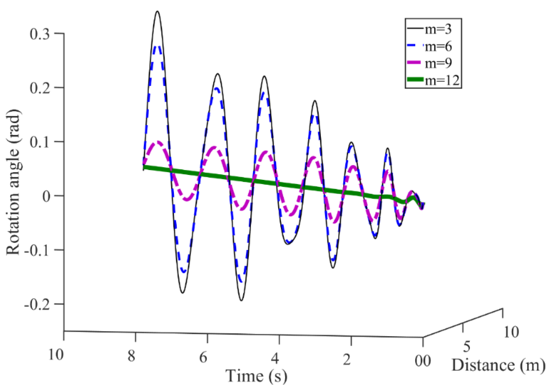
The aggregation order is taken as 3, 6, 9, and 12, respectively. As shown in Figure 9, the amplitudes of the rotation angle show an increasing trend in the first 10 s in all four cases. At the 0.5th s, the rotation angle is 0.1 rad, 0.09 rad, 0.06 rad, and 0.01 rad, respectively. Moreover, the rotation angle is 0.38 rad, 0.27 rad, 0.12 rad, and 0.05 rad at the 8th second, respectively. We can see that the rotation angle corresponding to the larger aggregation order keeps a smaller angle in the initial explosion stage and affects a much larger area. This implies that the predicted rotation angle is affected by order of compression wave aggregation.

2.3.4. Sensitive Analysis of Explosive Type

The explosive type is an important factor affecting the range and duration of an explosion [21]. This section will study the impact of explosive type on the rotation angle.
Three types of explosives are considered to investigate the impact of explosive type on gas production rate. They are Nitromathane, TATB, and PBX-9404, respectively [21,28]. Figure 10 presents the rotational with time and distance. Similarly, the amplitudes of the rotation angle show an increasing trend in the first 10 s in all four cases. At the 2th s, the rotation angle becomes 0.08 rad, 0.07 rad, and 0.065 rad, respectively. Further, at the 6th s, the rotation angle is 0.185 rad, 0.17 rad, and 0.16 rad, respectively. These results indicate that the type of explosive has a significant impact on the production of shale gas. In the same explosion period, the rotation angle triggered by Nitromathane increases faster and reaches a higher rotation angle. This is because the explosive of Nitromethane causes a lower initial C-J velocity, and the effect of the explosion is smaller and shorter.

3. Wave Propagation Mechanism from Shock Wave Stage to Elastic Wave Stage

3.1. Governing Equation of P-Wave Displacement

With the radial propagation of the detonation wave, the peak value of the local rotation angle decreases from θ 0 . The deformation style of shale gradually changes from crushing and impact failure to deformation under elastic wave action. The deformation gradient can be simplified into:
F j i ( α ) = | 1 0 0 1 + α u r α |
And the radial displacement of the detonation wave satisfies the following relationship:
α u r α + 1 = 1 cos θ
It automatically satisfies the continuity condition of the radial displacement gradient. The continuity condition of the local rotation angle of the medium is given as follows:
( 1 cos θ c ) 2 = 1 + sin 2 θ c
With respect to the shock wave deformation gradient (34), the shale skeleton maintains local continuity, and the motion equation of the P wave is:
( λ L + 2 μ ) 1 r 2 ( 1 + u r ) 2 r [ r 2 u r ] = ρ 2 u t 2
where ρ is the medium density, λ L is the Lame elastic constant, μ is the shear modulus, and:
λ L = 3 ν E ( 1 + ν ) ( 1 2 ν )
μ = E 2 ( 1 + ν )
where E is Young’s modulus of shale, and ν is Poisson’s ratio of shale.

3.2. Analytical Solutions of P-Wave Displacement

Equation (37) can be translated into:
2 u r 2 + 2 r u r = ρ λ L + 2 μ 2 u t 2
Therefore, the wave equation on the Cantor sets should be:
2 α u r 2 α + 2 r α α u r α = ρ λ L + 2 μ 2 α u t 2 α
Equation (41) can be translated into:
2 α ( r u ) t 2 α = λ L + 2 μ ρ 2 α ( r u ) r 2 α
For the convenience of solving, a new variable U is introduced, and:
U = r u
Integrating Equation (43) into Equation (42) yields:
2 α U ( r , t ) t 2 α = a 2 2 α U ( r , t ) r 2 α
Subject to the following initial-boundary conditions:
U ( r , 0 ) = E α ( r α )
α U ( r , 0 ) U α = 0
U ( R , t ) = U ( 0 , t ) = 0
α U ( R , t ) U α = α U ( 0 , t ) U α = 0
where R is the furthest distance a wave can travel, a 2 = λ L + 2 μ ρ .
The variational iteration method [17,29] solves the nonlinear problem (44). Its basic idea is briefed below. For a general partial differential equation below:
L α U ( ζ ) N α U ( ζ ) = 0
where L α is the linear operator of u above r , and N α is a nonlinear operator of φ .
Therefore, the correction functional is constructed as:
U n + 1 ( r , t ) = U n ( r , t ) - 0 t ( t ζ ) α Γ ( 1 + α ) { L α U n ( r , ζ ) + N α U ˜ n ( r , ζ ) } ( d ζ ) α
Considering the iterative Formula (51) with the initial value:
U 0 ( r , t ) = E α ( r α )
Integrating Equation (51) into Equation (50) yields
Following the process of derivation yields:
U 1 ( r , t ) = U 0 ( r , t ) 0 t ( t ζ ) α Γ ( 1 + α ) { 2 α U 0 ( r , ζ ) t 2 α a 2 2 α U 0 ( r , ζ ) r 2 α } ( d ζ ) α = E α ( r α ) 0 t ( t ζ ) α Γ ( 1 + α ) { a 2 E α ( r α ) } ( d ζ ) α = E α ( r α ) { a 2 E α ( r α ) } 0 t ( t ζ ) α Γ ( 1 + α ) ( d ζ ) α = E α ( r α ) + { a 2 E α ( r α ) } t 2 α Γ ( 1 + 2 α ) = E α ( r α ) ( 1 + a 2 t 2 α Γ ( 1 + 2 α ) )
U 2 ( r , t ) = U 1 ( r , t ) 0 t ( t ζ ) α Γ ( 1 + α ) { 2 α U 1 ( r , ζ ) t 2 α a 2 2 α U 1 ( r , ζ ) r 2 α } ( d ζ ) α = E α ( r α ) ( 1 + a 2 t 2 α Γ ( 1 + 2 α ) ) 0 t ( t ζ ) α Γ ( 1 + α ) { a 2 E α ( r α ) a 2 E α ( r α ) ( 1 + a 2 t 2 α Γ ( 1 + 2 α ) ) } ( d ζ ) α = E α ( r α ) ( 1 + a 2 t 2 α Γ ( 1 + 2 α ) ) 0 t ( t ζ ) α Γ ( 1 + α ) { a 2 E α ( r α ) a 2 t 2 α Γ ( 1 + 2 α ) } ( d ζ ) α = E α ( r α ) ( 1 + a 2 t 2 α Γ ( 1 + 2 α ) a 4 t 4 α Γ ( 1 + 4 α ) )
U 3 ( r , t ) = U 2 ( r , t ) 0 t ( t ζ ) α Γ ( 1 + α ) { 2 α U 2 ( r , ζ ) t 2 α a 2 2 α U 2 ( r , ζ ) r 2 α } ( d ζ ) α = - 0 t ( t ζ ) α Γ ( 1 + α ) { a 2 E α ( r α ) a 2 t 2 α Γ ( 1 + 2 α ) - a 4 E α ( r α ) ( t 2 α Γ ( 1 + 2 α ) a 2 t 4 α Γ ( 1 + 4 α ) ) } ( d ζ ) α + E α ( r α ) ( 1 + a 2 t 2 α Γ ( 1 + 2 α ) a 4 t 4 α Γ ( 1 + 4 α ) ) = - E α ( r α ) 0 t ( t ζ ) α Γ ( 1 + α ) { a 2 a 2 t 2 α Γ ( 1 + 2 α ) - a 4 ( t 2 α Γ ( 1 + 2 α ) a 2 t 4 α Γ ( 1 + 4 α ) ) } ( d ζ ) α + E α ( r α ) ( 1 + a 2 t 2 α Γ ( 1 + 2 α ) a 4 t 4 α Γ ( 1 + 4 α ) ) = E α ( r α ) ( 1 + a 2 t 2 α Γ ( 1 + 2 α ) a 4 t 4 α Γ ( 1 + 4 α ) ) + E α ( r α ) 0 t ( t ζ ) α Γ ( 1 + α ) { a 6 t 4 α Γ ( 1 + 4 α ) } ( d ζ ) α = E α ( r α ) ( 1 + a 2 t 2 α Γ ( 1 + 2 α ) a 4 t 4 α Γ ( 1 + 4 α ) + a 6 t 6 α Γ ( 1 + 6 α ) )
U 4 ( r , t ) = E α ( r α ) ( 1 + a 2 t 2 α Γ ( 1 + 2 α ) a 4 t 4 α Γ ( 1 + 4 α ) + a 6 t 6 α Γ ( 1 + 6 α ) a 8 t 8 α Γ ( 1 + 8 α ) )
Following the process of derivation yields:
U n + 1 ( r , t ) = U n ( r , t ) + I r 2 α 0 ( 2 α U n ( r , ζ ) t 2 α a 2 2 α U n ( r , ζ ) r 2 α ) = 0 n a 2 n t 2 n α Γ ( 1 + 2 n α ) E α ( r α )
Finally, the solution of Equation (44) yields:
U ( r , t ) = E α ( r α ) r n = 0 a 2 n t 2 n α Γ ( 1 + 2 n α ) = E α ( r α ) r cosh α ( a t α )
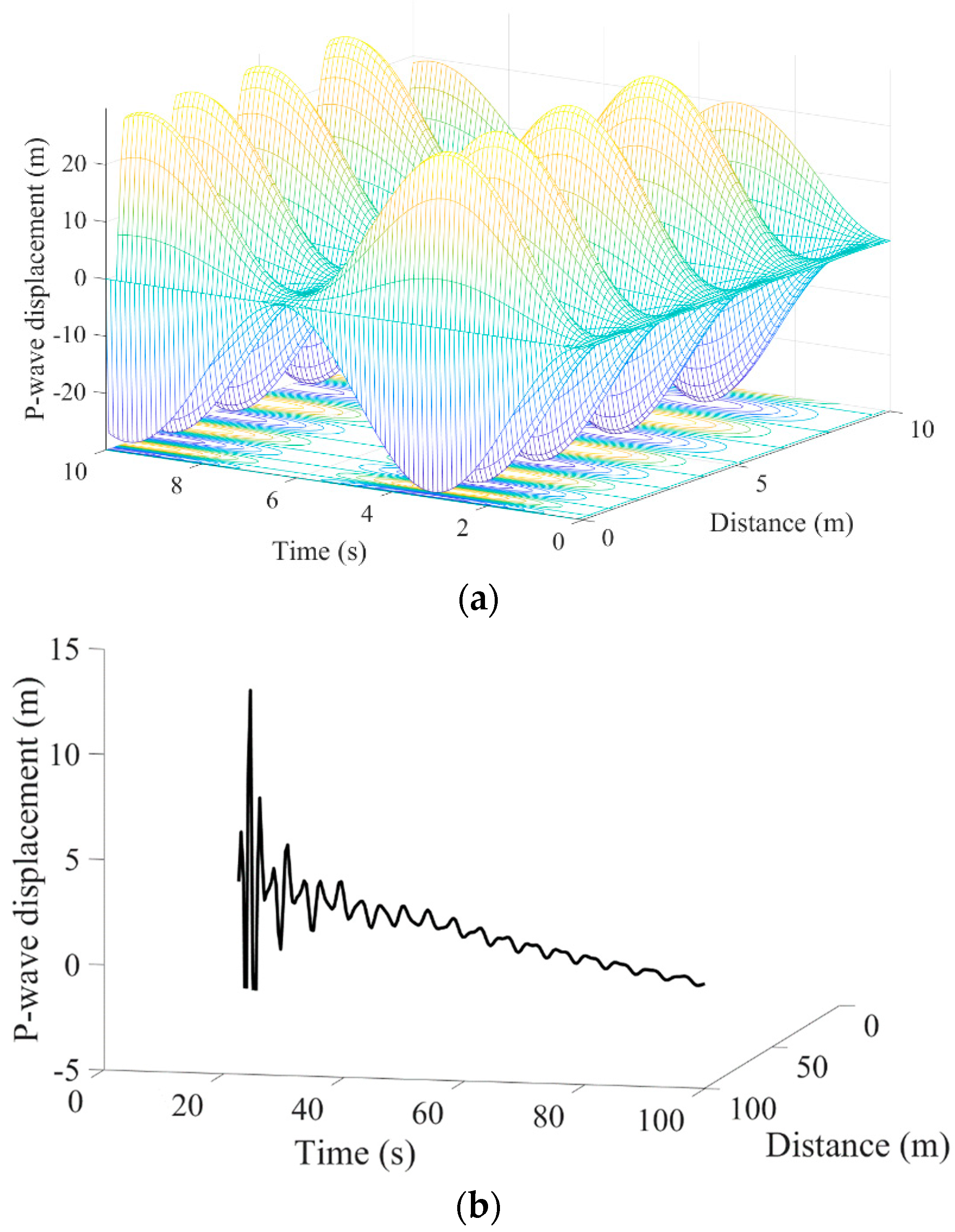
and its plot is shown in Figure 11.

3.3. Discussion

The above model describes the wave propagation process of elastic waves, including attenuation of shock waves and elastic wave propagation. An analytical solution of P-wave displacement is obtained. The result is successfully applied to model the wave propagation in a fractal shale reservoir.
The graph of P-wave displacement with time and distance is displayed in Figure 12. It can be seen that the wave displacement fluctuates, and the value of the shock wave peak increases for a very short time and then decreases over time. Taking the point 0.108 m from the detonation center as an example, with the wave propagation after the explosion, the elastic wave decays by the effect of the wave propagation boundary. The amplitude of the elastic wave declines and decreases by about 40% from 20 s to 30 s. As shown in Figure 12b, at the 20 s, the amplitude of the P-wave reaches 13 m, and then sharply descends during the later production period. At 100 s, the amplitude of the P-wave keeps about 0.5 m in the explosion tail. In addition, the P-wave displacement decreases as the distance increases. With the distance further away from the explosion center, the influence range and intensity of stress wave caused by combustion–explosion become weaker and weaker.

4. Conclusions

In this work, two novel local fractional wave propagation models in the process of combustion–explosion fracturing for shale reservoirs. The two fractional models were analytically solved through the separation of variables and the variational iteration method, respectively. The analytical solutions were used to predict the rotation angle from the detonation wave stage to the shock wave stage, and the P-wave displacement at the elastic wave stage. Based on these studies, the following conclusions can be made:
First, the branching parameter of the detonation wave converge bifurcation system influences the wave propagation in combustion–explosion shale reservoir fracturing. It cannot be ignored as it is part of what influences the prediction propagation and influence range.
Second, the aggregation order of compression wave affects the wave propagation. The rotation angle corresponding to the larger aggregation order keeps a lesser angle in the initial stage of the explosion. It can affect a much larger area during the process of combustion–explosion fracturing.
Third, the explosive type has a significant impact on the wave propagation range and duration of an explosion. In our computation case, the rotation angle triggered by Nitromathane increases faster and reaches a higher rotation angle, while the effect of the explosion by PBX-9404 is larger and longer.
Finally, from the shock wave stage to the elastic wave propagation stage, the wave amplitude shows the trend of a sudden rise followed by a slow decline, while the influence range of the P-wave becomes weaker and weaker with distance.

Author Contributions

Conceptualization, X.S. and Z.Z.; methodology, W.Y.; validation, X.S. and Z.Z.; formal analysis, X.S.; investigation, W.Y.; resources, C.Z.; data curation, Z.Z.; writing—original draft preparation, X.S.; writing—review and editing, Z.Z. and W.Y.; visualization, J.G.W.; supervision, W.Y.; project administration, W.Y.; funding acquisition, C.Z. and X.S. All authors have read and agreed to the published version of the manuscript.

Funding

This research was funded by financial support by the National Key R&D Program of China (Grant No. 2020YFA0711800), National Natural Science Foundation of China (Grant No. 52174091, No. 52204113), Natural Science Foundation of Jiangsu Province for Youth Foundation (Grant No. BK20220232), and China Postdoctoral Science Foundation (Grant No. 2020M681772).

Institutional Review Board Statement

Not applicable.

Informed Consent Statement

Not applicable.

Data Availability Statement

Not applicable.

Conflicts of Interest

The authors declare no conflict of interest.

References

  1. Hughes, J.D. Energy: A reality check on the shale revolution. Nature 2013, 494, 307–308. [Google Scholar] [CrossRef]
  2. Wu, J.J.; Liu, L.C.; Zhao, G.H.; Chu, X.S. Research and exploration of high energy gas fracturing stimulation integrated technology in Chinese shale gas reservoir. Adv. Mater. Res. 2012, 524–527, 1532–1536. [Google Scholar]
  3. Mahdaviara, M.; Sharifi, M.; Ahmadi, M. Toward evaluation and screening of the enhanced oil recovery scenarios for low permeability reservoirs using statistical and machine learning techniques. Fuel 2022, 325, 124795. [Google Scholar] [CrossRef]
  4. Wu, J.J.; Liu, J.; Zhao, J.Z.; Du, F. Research on explosive fracturing technology of liquid explosives in micro-cracks in low permeability reservoirs. Mater. Sci. Eng. 2019, 592, 4–6. [Google Scholar] [CrossRef]
  5. Wu, F.P.; Wei, X.M.; Chen, Z.X.; Rahman, S.S.; Pu, C.S.; Li, X.J.; Zhang, Y.Y. Numerical simulation and parametric analysis for designing high energy gas fracturing. J. Nat. Gas Sci. Eng. 2018, 53, 218–236. [Google Scholar] [CrossRef]
  6. Roberts, L.N. Liquid Explosive for Well Fracturing; U.S.P.: Rockville, MD, USA, 1974; p. 3825452. [Google Scholar]
  7. Ye, Q.; Lin, B.Q.; Jia, Z.Z.; Zhu, C.J. Propagation law and analysis of gas explosion in bend duct. Procedia Earth Planet. Sci. 2009, 1, 316–321. [Google Scholar]
  8. Shang, X.J.; Wang, J.G.; Zhang, Z.Z.; Gao, F. A three-parameter permeability model for the cracking process of fractured rocks under temperature change and external loading. Int. J. Rock Mech. Min. 2019, 123, 104106. [Google Scholar] [CrossRef]
  9. Wang, F.; Cheng, H. A fractal permeability model for 2D complex tortuous fractured porous media. J. Petrol. Sci. Eng. 2020, 188, 106938. [Google Scholar] [CrossRef]
  10. Ma, C.; Zhu, C.J.; Zhou, J.X.; Ren, J.; Yu, Q. Dynamic response and failure characteristics of combined rocks under confining pressure. Sci. Rep. 2022, 12, 12187. [Google Scholar] [CrossRef]
  11. Smoller, J. Shock Waves and Reaction-Diffusion Equations; Springer: New York, NY, USA, 1983; pp. 337–358. [Google Scholar]
  12. Tahir, S.I.; Tounsi, A.; Chikh, A.; Al-Osta, M.A.; Al-Dulaijan, S.U.; Al-Zahrani, M.M. The effect of three-variable viscoelastic foundation on the wave propagation in functionally graded sandwich plates via a simple quasi-3D HSDT. Stell Compos. Struct. 2022, 42, 501–511. [Google Scholar]
  13. Tahir, S.I.; Chikh, A.; Tounsi, A.; Al-Osta, M.A.; Al-Dulaijan, S.U.; Al-Zahrani, M.M. Wave propagation analysis of a ceramic-metal functionally graded sandwich plate with different porosity distributions in a hygro-thermal environment. Compos. Struct. 2021, 269, 114030. [Google Scholar] [CrossRef]
  14. Zhang, P.; Zhang, Y.J.; Huang, Y.B.; Xia, Y. Experimental study of fracture evolution in enhanced geothermal systems based on fractal theory. Geothermics 2022, 102, 102406. [Google Scholar] [CrossRef]
  15. Mustafa, S.; Hajira; Khan, H.; Shah, R.; Masood, S. A novel analytical approach for the solution of fractional-order diffusion-wave equations. Fractal Fract. 2021, 5, 206. [Google Scholar] [CrossRef]
  16. Baleanu, D.; Jassim, H.K. Approximate solutions of the damped wave equation and dissipative wave equation in fractal strings. Fractal Fract. 2019, 3, 26. [Google Scholar] [CrossRef] [Green Version]
  17. Yang, Y.J.; Baleanu, D.; Yang, X.J. A local fractional variational iteration method for Laplace equation within local fractional operators. Abstr. Appl. Anal. 2013, 2013, 202650. [Google Scholar] [CrossRef] [Green Version]
  18. Shang, X.J.; Wang, J.G.; Zhang, Z.Z. Analytical solutions of fractal-hydro-thermal model for two-phase flow in thermal stimulation enhanced coalbed methane recovery. Therm. Sci. 2019, 23, 1345–1353. [Google Scholar] [CrossRef] [Green Version]
  19. Shang, X.J.; Wang, J.G.; Yang, X.J. Fractal analysis for heat extraction in geothermal system. Therm. Sci. 2017, 21, S25–S31. [Google Scholar] [CrossRef]
  20. Hou, R.; Xu, W.B. The Traveling Wave Solutions in a Mixed-Diffusion Epidemic Model. Fractal Fract. 2022, 6, 217. [Google Scholar] [CrossRef]
  21. Hong, T.; Wang, H. Analytical solution for unsteady two-dimensional detonation two-dimensional detonation wave with DSD method. Explo. Shock Waves 1996, 16, 317–325. (In Chinese) [Google Scholar]
  22. Jones, J. The spherical detonation. Adv. Appl. Math. 1991, 12, 147–186. [Google Scholar] [CrossRef] [Green Version]
  23. Liu, Y.; Huang, F.L.; Wu, Y.Q.; Long, R.R. Explosion Physics; Beijing Institute of Technology Press: Beijing, China, 2019; pp. 60–68. [Google Scholar]
  24. Yu, B.B.; Xu, P.; Zou, M.Q.; Cai, J.C.; Zheng, Q. Transport Physics of Fractal Porous Media; Science Press: Beijing, China, 2014; pp. 131–149. [Google Scholar]
  25. Bdzil, J.B. Modeling two-dimension with detonation shock dynamics. Phy. Fluids 1989, 1, 1261–1267. [Google Scholar] [CrossRef] [Green Version]
  26. Lambourn, B.D. Application of Whitham’s shock dynamics theory to the propagation of divergent detonation waves, In 9th Symp (Intern) on Detonation; Office of Naval Research: Portland, OR, USA, 1989; pp. 784–797. [Google Scholar]
  27. Chen, Y.; Huang, T.F.; Liu, E.R. Rock Physics; University of Science and Technology of China Press: Hefei, China, 2009; pp. 79–85. [Google Scholar]
  28. Wei, Y.Z. Detonation and propagation behavior of TATB explosive. In Internal Report of Institute of Fluid Physics; CAEP: Mianyang, China, 1991. [Google Scholar]
  29. Shang, X.J.; Wang, J.G.; Zhang, Z.Z. Iterative analytical solutions for nonlinear two-phase flow with gas solubility in shale gas reservoirs. Geofluids 2019, 2019, 4943582. [Google Scholar] [CrossRef]
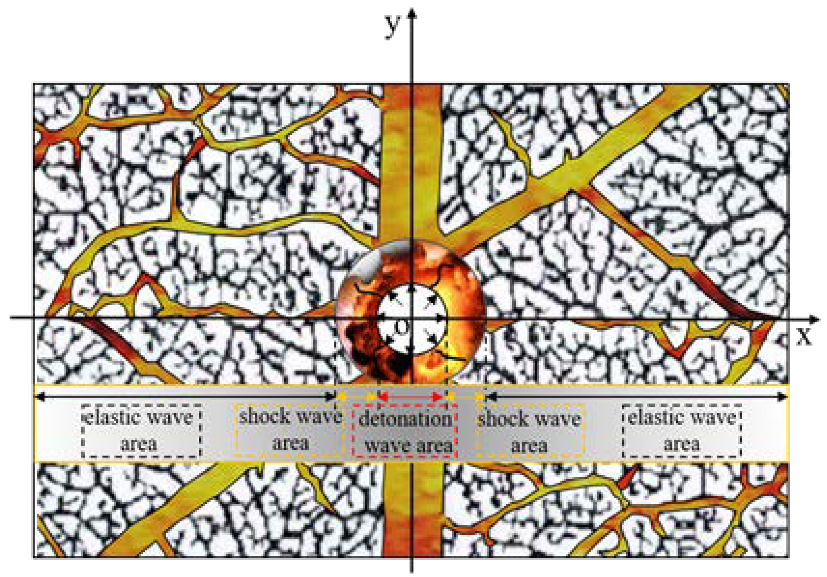
Figure 1. Diagram of fracture propagation caused by combustion-explosion in shale reservoir.
Fractalfract 06 00632 g001
Figure 2. Diagram of detonation wave front [23]. ① Primary explosive, leading shock wave of cross-section N N ② Chemical reaction zone, reaction ends in the cross-section M M ③ terminates product of the detonation.
Fractalfract 06 00632 g002
Figure 3. Path of compression waves converging into a shock wave. (a) single-stage bifurcation structure. (b) multistage bifurcation structures.
Fractalfract 06 00632 g003
Figure 4. Convergence from compression wave into shock wave in the orthogonal coordinate (x, y).
Fractalfract 06 00632 g004
Figure 5. Schematic diagram of detonation wave surface.
Fractalfract 06 00632 g005
Figure 6. Nondifferentiable solution of local rotation angle with nondifferentiable sink term for α = ln 2 / ln 3 .
Fractalfract 06 00632 g006
Figure 7. Change of rotation angle of shock wave with time and distance.
Fractalfract 06 00632 g007
Figure 8. Impact of branching parameter on rotation angle.
Fractalfract 06 00632 g008
Figure 9. Impact of aggregation order on rotation angle.
Fractalfract 06 00632 g009
Figure 10. Impact of explosive type on rotation angle.
Fractalfract 06 00632 g010
Figure 11. Nondifferentiable solution of P-wave displacement with nondifferentiable sink term for α = ln 2 / ln 3 .
Fractalfract 06 00632 g011
Figure 12. Change of P-wave displacement of the elastic wave with time and distance. (a) P-wave displacement over a short time and small scope. (b) P-wave displacement over a wide range and long period.
Fractalfract 06 00632 g012
Table 1. Model parameters in computation of analytical model.
ParameterUnitValuePhysical Meanings
X 4branching parameter of fractured shale
m 10grades of bifurcated pipes
v C J , 0 m / s 6209compression wave velocity of the 0-th pipe
b 0.875constant related to nature of the explosive
R m0.108radius of detonation wave area
α ln2/ln3fractional order
EMPa7500Young’s modulus of shale
ν 0.25Poisson’s ratio of shale
ρ kg / m 3 2600density of shale
U 0 m0.108initial displacement of shock wave
Publisher’s Note: MDPI stays neutral with regard to jurisdictional claims in published maps and institutional affiliations.