Article

Cabinet of Curiosities: The Interesting Geometry of the Angle β = arccos ((3ϕ − 1)/4)

Quantum Gravity Research, Topanga, CA 90290, USA
*
Author to whom correspondence should be addressed.
Fractal Fract. 2019, 3(4), 48; https://doi.org/10.3390/fractalfract3040048
Submission received: 12 September 2019 / Revised: 26 October 2019 / Accepted: 27 October 2019 / Published: 30 October 2019

Abstract

:
In this paper, we present the construction of several aggregates of tetrahedra. Each construction is obtained by performing rotations on an initial set of tetrahedra that either (1) contains gaps between adjacent tetrahedra, or (2) exhibits an aperiodic nature. Following this rotation, gaps of the former case are “closed” (in the sense that faces of adjacent tetrahedra are brought into contact to form a “face junction”), while translational and rotational symmetries are obtained in the latter case. In all cases, an angular displacement of β = arccos 3 ϕ 1 / 4 (or a closely related angle), where ϕ = 1 + 5 / 2 is the golden ratio, is observed between faces of a junction. Additionally, the overall number of plane classes, defined as the number of distinct facial orientations in the collection of tetrahedra, is reduced following the transformation. Finally, we present several “curiosities” involving the structures discussed here with the goal of inspiring the reader’s interest in constructions of this nature and their attending, interesting properties.

1. Introduction

The present document introduces the reader to the angle β = arccos 3 ϕ 1 / 4 , where ϕ = 1 + 5 / 2 is the golden ratio, and its involvement, most notably, in the construction of several interesting aggregates of regular tetrahedra. In the sections below, we will perform geometric rotations on tetrahedra arranged about a common central point, common vertex, common edge, as well as those of a linear, helical arrangement known as the Boerdijk–Coxeter helix (tetrahelix) [1,2]. In each of these transformations, the angle β above appears in the projections of coincident tetrahedral faces. Noteworthy about these transformations is that they have a tendency to bring previously separated faces of “adjacent” tetrahedra into contact [3] and to impart a periodic nature to previously aperiodic structures. Additionally, after performing the rotations described below, one observes a reduction in the total number of plane classes, defined as the total number of distinct facial or planar orientations in a given aggregation of polyhedra. These aggregates of tetrahedra might give clues to periodic tetrahedral packing in quasicrystals [4].

2. Aggregates of Tetrahedra

In this section, we describe the construction of several interesting aggregates of regular tetrahedra. The aggregates of Section 2.1 and Section 2.2 initially contain gaps of various sizes. By performing special rotations of these tetrahedra, these gaps are “closed” (in the sense that faces of adjacent tetrahedra are made to touch), and, in each case, the resulting angular displacement between coincident faces is either identically equal to β or is closely related. In Section 2.3, a rotation by β is imparted to tetrahedra arranged in a helical fashion in order to introduce a periodic structure and previously unpossessed symmetries.

2.1. Aggregates about a Common Edge

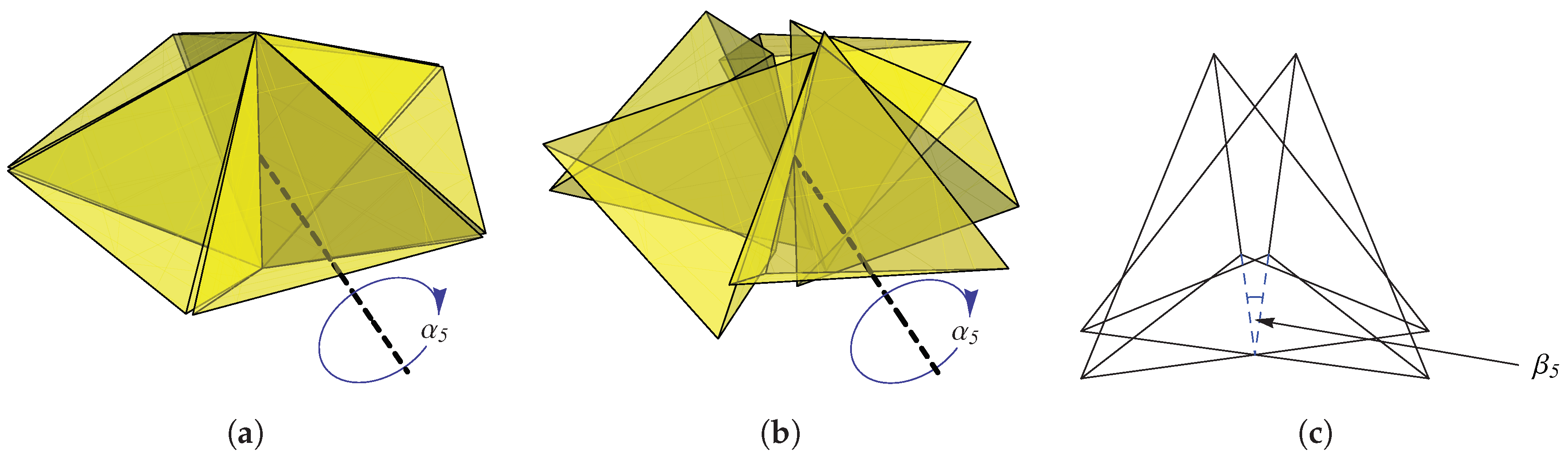
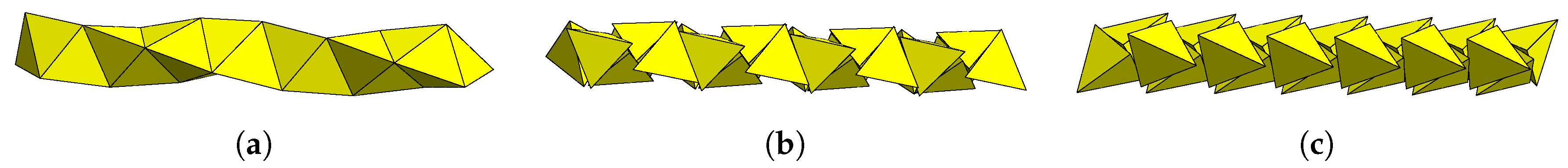
Consider aggregates of n regular tetrahedra, 3 n 5 , arranged about a common edge (so that an angle of 2 π / n is subtended between adjacent tetrahedral centers; see 
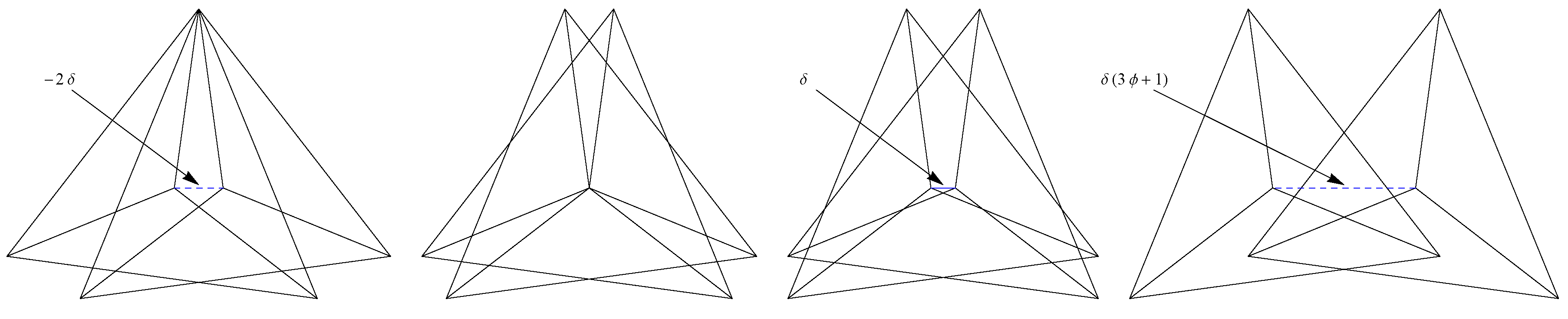
Figure 1a for an example with five tetrahedra). In each of these structures, gaps exist between tetrahedra that may be “closed” (i.e., faces are made to touch) by performing a rotation of each tetrahedron about an axis passing between the midpoints of its central and peripheral edges through an angle given by
α n = arctan cos 2 γ 2 cos 2 θ n 2 sin γ 2 cos θ n 2 ,
where γ = arccos ( 1 / 3 ) is the tetrahedral dihedral angle and θ n = 2 π / n . When this is done, an angle, β n , is established in the “face junction” between coincident pairs of faces such that
β n = 2 arctan cos 2 γ 2 cos 2 θ n 2 cos θ n 2 .
The present document is focused on the angle β = arccos 3 ϕ 1 / 4 , which is, in fact, the angle obtained in the “face junction” produced by executing the above procedure for n = 5 tetrahedra (see 
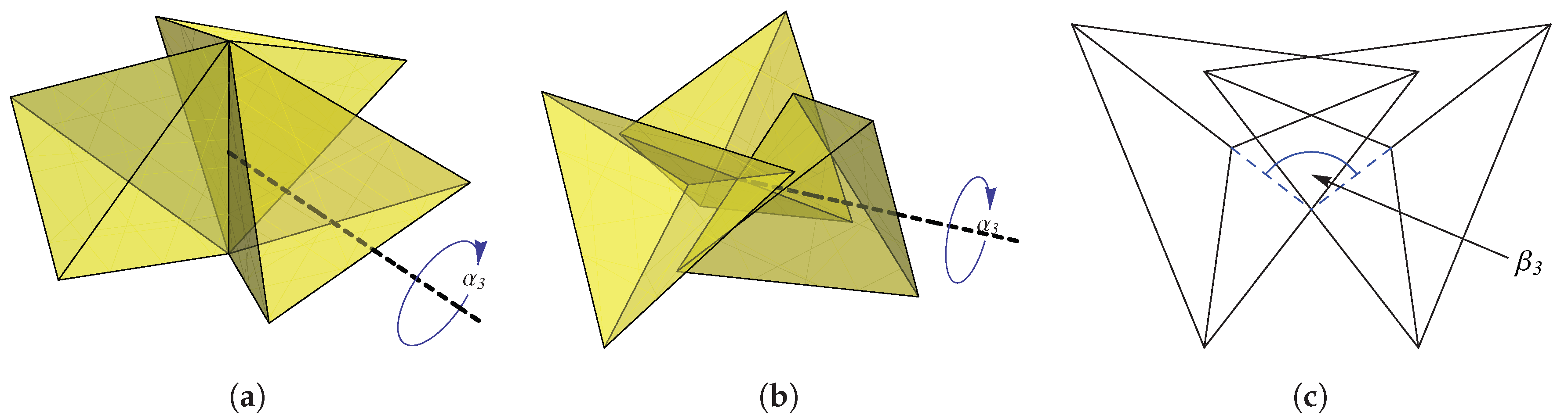
Figure 1). It is interesting, however, that a simple relationship may be established between this angle and β 3 . By evenly arranging three tetrahedra about an edge and rotating each through the axis extending between the central and peripheral edge midpoints, the face junction depicted in Figure 2c is obtained. The angle between faces in this junction, β 3 , may be related to β in the following way:
2 π 3 β = β 3 .
To see this, note that
2 π 3 arccos 3 ϕ 1 4 = 2 arctan cos 2 γ 2 cos 2 θ 2 cos θ 2
gives the solution θ = ± 2 π 3 , which reduces the right-hand side of Equation (4) to β 3 .
In this section, we have produced two aggregates of tetrahedra whose face junctions bear a relationship to the angle β = arccos 3 ϕ 1 / 4 . In the section that follows, we will locate this angle in the face junctions produced through rotations of tetrahedra about a common vertex.

2.2. Aggregates about a Common Vertex

Consider the icosahedral aggregation of 20 tetrahedra depicted in Figure 3a. The face junction of Figure 3c is obtained when each tetrahedron is rotated by an angle of
α 20 = arccos ϕ 2 2 2
about an axis extending between the center of its exterior face and the arrangement’s central vertex. As above, this operation “closes” gaps between tetrahedra by bringing adjacent faces into contact. Interestingly, the face junction obtained here consists of tetrahedra with a rotational displacement equal to the one obtained in the case of five tetrahedra arranged about a common edge above, i.e., β 20 = β 5 = β . (It should be noted, however, that α 20 and β 20 are not produced by Equations (1) and (2), respectively, as those formulæ are only valid for 3 n 5 .)
In all of the cases described above, gaps are “closed” and “junctions” are produced between adjacent tetrahedra in such a way that the angle β = arccos 3 ϕ 1 / 4 appears in some fashion in the angular displacement between coincident faces. For the cases of 5 tetrahedra about a central edge and 20 tetrahedra about a common vertex, this angle is observed directly. For the case of 3 tetrahedra about a central edge, the angular displacement between faces is closely related: β 3 = 2 π 3 β .
We now turn to an arrangement obtained by directly imparting an angular displacement of β between adjacent pairs of tetrahedra in a linear, helical fashion known as the Boerdijk–Coxeter helix. An interesting result of performing this action is that a previously aperiodic structure is transformed into one with translational and rotational symmetries.

2.3. Periodic, Helical Aggregates

In Section 2.1 and Section 2.2, we described a procedure by which initial arrangements of tetrahedra were transformed so that adjacent pairs of tetrahedra were brought together to touch. In each of these structures, coincident faces are displaced by an angle equal or closely related to β . Here, we will construct two periodic, helical chains of tetrahedra by directly inserting an angular offset by β between each successive member of the chain. For their close relationship with the Boerdijk–Coxeter helix, we refer to these structures by the term modified BC helices.
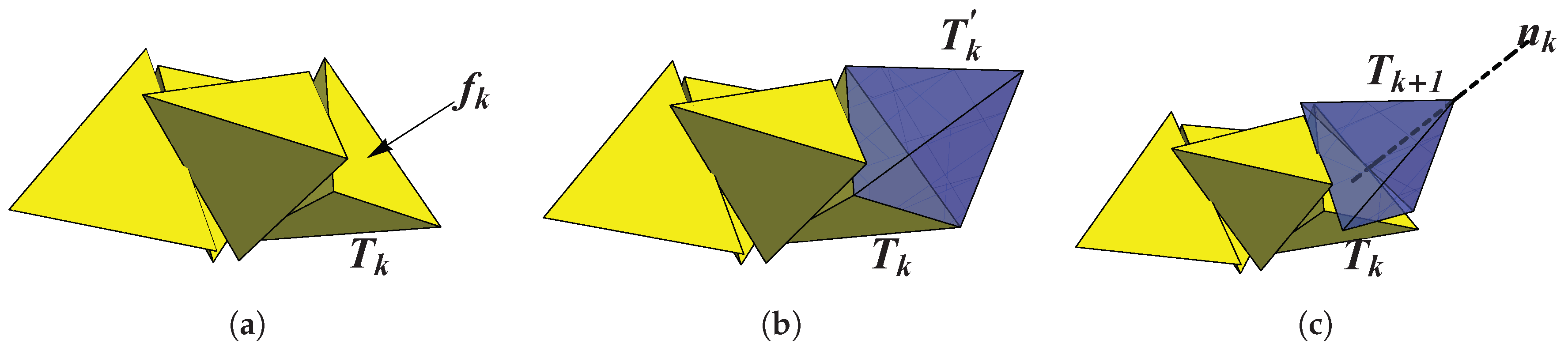
The construction of a modified BC helix is depicted in Figure 4. Starting from a tetrahedron T k = v k 0 , v k 1 , v k 2 , v k 3 , a face f k is selected onto which an interim tetrahedron, T k , is appended. The k + 1 th tetrahedron is obtained by rotating T k through an angle β about an axis n k normal to f k , passing through the centroid of T k . (Note that this automatically produces an angular displacement of β between two faces in a “junction”, see Figure 5a).
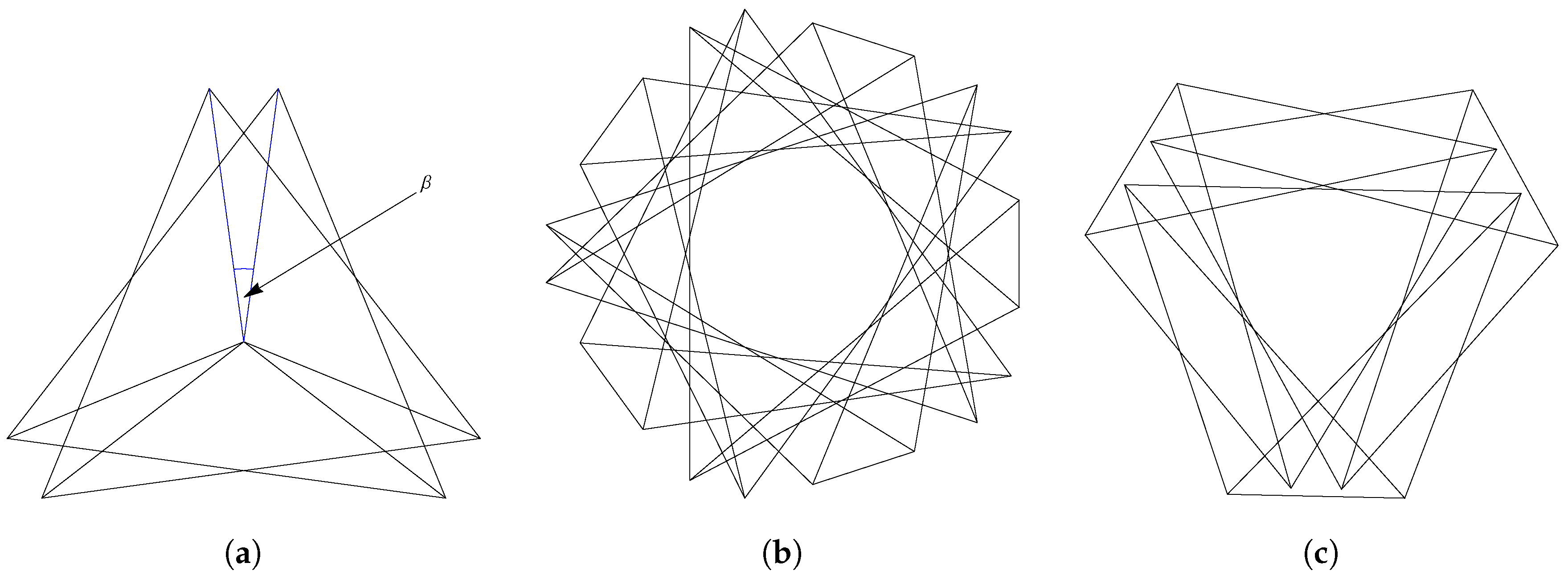
The structure that results from this process depends on the sequence of faces F = f 0 , f 1 , , f k selected in order to construct the helical chain. This sequence determines an underlying chirality of the helix—i.e., the chirality of the helix formed by the tetrahedral centroids—and plays a pivotal role in the determination of the structure’s eventual symmetry. (However, it should be noted, of course, that some sequences of faces do not result in helical structures. Faces cannot be chosen arbitrarily or randomly; they must be selected so as to build a helix).
By performing the procedure depicted in Figure 4, using an angular displacement of β between successive tetrahedra, periodic structures are obtained with 3- or 5-fold symmetry (upon their projections, see Figure 6b,c), depending on the relative chiralities between the rotational displacement and the underlying helix: When like chiralities are used, one obtains 5-fold symmetry; when unlike chiralities are used, one obtains 3-fold symmetry. In addition to rotational symmetry, these structures are given a linear period, which we quantify here as the number of appended tetrahedra necessary to return to an initial angular position on the helix. For a modified BC helix with a period of m tetrahedra, we use the term m-BC helix. Accordingly, the procedure described above produces 3- and 5-BC helices, which are shown in Figure 6. (See [5] for a proof of these structures’ symmetries and periodicities).

3. Curiosities

We have seen the construction of several aggregates of tetrahedra. Each of these structures contains tetrahedra with coincident faces, offset angularly by β or a closely related angle ( 2 π 3 β ). We will now explore some of the interesting features of these structures. As already noted, it is interesting that β appears in the face junctions of structures generated by “closing” gaps between tetrahedral aggregates. It is additionally interesting that when this angle is employed in the construction of a helical chain of tetrahedra, a periodic structure emerges (whereas the canonical BC helix has no non-trivial translational or rotational symmetries).
The features we will highlight in this section involve the reduction of the overall number of “plane classes” and the linear displacements between facial centers in a face function. Here, we say that two planes belong to the same plane class if and only if their normal vectors are parallel. The number of plane classes for a collection of tetrahedra, then, is defined as the number of distinct plane classes comprising the collection’s two-dimensional faces. By rotating tetrahedra so as to bring faces into contact (as in Section 2.1 and Section 2.2), or rotating tetrahedra to obtain periodicity (as in Section 2.3), the overall number of plane classes for an aggregate is reduced. Clearly, as the values of α 3 , α 5 , and α 20 are such that they bring faces of adjacent tetrahedra into contact, we would expect to see a reduction in the number of plane classes in the corresponding aggregations of tetrahedra featured in Section 2.1 and Section 2.2. It is interesting, however, that rotation of the tetrahedra in a BC helix by β (observed in the face junctions of Figure 1c, Figure 2c and Figure 3c) obtains a reduction from an arbitrarily large number of plane classes ( 3 n + 1 , where n is the number of tetrahedra in the helix) to relatively small numbers: 9 plane classes in the case of the 3-BC helix, 10 plane classes in the case of the 5-BC helix. Table 1 provides the numbers of plane classes for the tetrahedral aggregates described in Section 2 before and after their transformations.
Finally, an appealing feature is observed in the face junction projections of the tetrahedral aggregates discussed in this paper. Figure 7 provides a side-by-side comparison of these face junctions. As the angular displacement between tetrahedra in all face junctions is related to β , we can see that translation of a tetrahedron in one junction can produce any of the other junctions. Let the displacement between tetrahedra in the face junction of 5 tetrahedra about a common edge be denoted by δ = a 2 ϕ 2 6 , 0 , where a is the tetrahedron edge length. Starting from the face junction of a 3- or 5-BC helix, the remaining face junctions corresponding to 20 tetrahedra about a vertex, 5 tetrahedra about an edge, and 3 tetrahedra about an edge may be obtained by translating a tetrahedron of the junction by 2 δ , δ , and 3 ϕ + 1 δ , respectively.

4. Conclusions

In this paper, we have presented the construction of several aggregates of tetrahedra. In each case, the construction process involved rotations of tetrahedra by a value related to β = arccos 3 ϕ 1 / 4 . The structures produced here have several notable features: Faces of tetrahedra are made to touch (“closing” previously existing gaps between tetrahedra), aperiodic structures are imparted with periodicity, and the total number of plane classes is reduced, as shown in Figure 1, Figure 2, Figure 3 and Figure 4. The purpose of the present document, however, is not merely descriptive; it is hoped that these notable features have generated interest in the reader of rotational transformations of tetrahedra involving the angle β . In particular, it is desired that further observations may be found that transform aggregates of tetrahedra such that faces are brought into contact and the number of plane classes is reduced, as shown in Table 1. These aggregates of tetrahedra could link tetrahedral packing to quasicrystals.

Author Contributions

Conceptualization, F.F. and K.I.; Investigation, F.F., J.K. and G.S.; Methodology and Writing Manuscript, G.S. and F.F.; Software, G.S. and F.F.; Supervision, K.I.

Funding

This research received no external funding.

Conflicts of Interest

The authors declare no conflict of interest.

References

  1. Coxeter, H.S.M. Regular Complex Polytopes; Cambridge University: Cambridge, UK, 1974. [Google Scholar]
  2. Boerdijk, A.H. Some remarks concerning close-packing of equal spheres. Philips Res. Rep. 1952, 7, 30. [Google Scholar]
  3. Fang, F.; Clawson, R.; Irwin, K. Closing Gaps in Geometrically Frustrated Symmetric Clusters: Local Equivalence between Discrete Curvature and Twist Transformations. Crystals 2018, 6, 89. [Google Scholar] [CrossRef]
  4. Fang, F.; Irwin, K. An Icosahedral Quasicrystal as a Golden Modification of the Icosagrid and its Connection to the E8 Lattice. arViv 2015, arViv:1511.07786. [Google Scholar] [CrossRef]
  5. Sadler, G.; Fang, F.; Clawson, R.; Irwin, K. Periodic modification of the Boerdijk-Coxeter helix (tetrahelix). Mathematics 2019, 7, 1001. [Google Scholar] [CrossRef]
Figure 1. “Twisting” tetrahedra centered about a common central edge to close up gaps between adjacent tetrahedra. When this operation is performed, the angle β = arccos ((3ϕ − 1)/4) is produced in the projection of a “face junction”. (a) Five tetrahedra arranged about a common edge. In this arrangement, small gaps exist between the faces of adjacent tetrahedra. Each tetrahedron is to be rotated by α5 about an axis passing between the midpoints of its central and peripheral edges. (b) The tetrahedra after rotation. In this arrangement, the faces of adjacent tetrahedra have been brought into contact with one another. (c) A projection of a “face junction” between two coincident faces in Figure 1b. The angular displacement between the faces is β5 = β.
Fractalfract 03 00048 g001
Figure 2. Arranging and rotating three tetrahedra (as done in the n = 5 case) to “close up” gaps between adjacent tetrahedra. When this operation is performed, the angle β 3 = 2 π 3 β is produced in the projection of a “face junction”. (a) Three tetrahedra arranged about a common edge. In this arrangement, large gaps exist between the faces of adjacent tetrahedra. Each tetrahedron is to be rotated by α3 about an axis passing between the midpoints of its central and peripheral edges. (b) The tetrahedra after rotation. In this arrangement, the faces of adjacent tetrahedra have been brought into contact with one another. (c) A projection of a “face junction” between two coincident faces in Figure 2b. The angular displacement between the faces is β3.
Fractalfract 03 00048 g002
Figure 3. When 20 tetrahedra are organized into an icosahedral arrangement, gaps between adjacent tetrahedra may be “closed” by performing a rotation of each tetrahedron by α20 about an axis passing from the central vertex through each tetrahedron’s exterior face. When this is done, an angle of β is produced in the projection of faces in a “face junction”. (a) Twenty tetrahedra arranged with icosahedral symmetry about a common central vertex. In this arrangement, gaps exist between faces of adjacent tetrahedra. Each tetrahedron is to be rotated by α20 about an axis passing from the central vertex through its exterior face. (b) The tetrahedra after rotation. Like in the cases above, the faces of adjacent tetrahedra have been brought into contact. (c) A projection of the “face junction” between two coincident faces in Figure 3b. The angular displacement between the faces is β20 = β5 = β.
Fractalfract 03 00048 g003
Figure 4. Assembly of a modified BC helix. (a) A segment of a modified BC helix with face fk identified on tetrahedron Tk. (b) An intermediate tetrahedron, T k (shown in blue), is appended (face-to-face) to fk on Tk. (c) Finally, Tk+1 is obtained by rotating T k through the angle β about the axis nk.
Fractalfract 03 00048 g004
Figure 5. BC helix projections and face junction. (a) A “face junction” between tetrahedra of a 3-or 5-BC helix. (b) A projection of the 5-BC helix along its central axis, showing five-fold symmetry. (c) A projection of the 3-BC helix along its central axis, showing three-fold symmetry.
Fractalfract 03 00048 g005
Figure 6. Canonical and modified Boerdijk–Coxeter helices. (a) A right-handed BC helix. (b) A “5-BC helix” may be obtained by appending and rotating tetrahedra by β using the same chirality of the underlying helix. (c) A “3-BC helix” may be obtained by appending and rotating tetrahedra by β using the opposite chirality of the underlying helix.
Fractalfract 03 00048 g006
Figure 7. Side-by-side comparison of face junctions. All face junctions may be obtained by translation of the (projected) tetrahedra of the 3- and 5-BC helix (pictured center left) by integer- and golden-ratio-based multiples of δ = a 2 ϕ 2 6 , 0 , where a is the tetrahedron edge length, the displacement between tetrahedra of a face junction for 5 tetrahedra about a common edge (pictured center right). From left to right, the displacements between the tetrahedra are 2 δ , 0, δ , and 3 ϕ + 1 δ .
Fractalfract 03 00048 g007
Table 1. Plane class numbers for aggregates described in Section 2.
Structure α n β n Plane Classes
BeforeAfter
3 tetrahedra, common edge arccos 1 6 2 π 3 arccos 3 ϕ 1 4 129
4 tetrahedra, common edge π 4 π 3 164
5 tetrahedra, common edge arccos ϕ 2 2 ϕ + 2 arccos 3 ϕ 1 4 2010
20 tetrahedra, common vertex arccos ϕ 2 2 2 arccos 3 ϕ 1 4 6010
n-tetrahedron 3-BC helixn/a arccos 3 ϕ 1 4 3 n + 1 9
n-tetrahedron 5-BC helixn/a arccos 3 ϕ 1 4 3 n + 1 10

