Article

Creep Behavior and Fractional-Order Viscoelastic-Plastic Damage Model of Polyethylene Fiber-Modified High-Water Material

School of Civil Engineering and Transportation, North China University of Water Resources and Electric Power, Zhengzhou 450045, China
*
Author to whom correspondence should be addressed.
Fractal Fract. 2026, 10(2), 95; https://doi.org/10.3390/fractalfract10020095
Submission received: 5 January 2026 / Revised: 24 January 2026 / Accepted: 26 January 2026 / Published: 28 January 2026
(This article belongs to the Section Engineering)

Abstract

High-water material (HWM) is widely used for roadside filling in gob-side entry retaining (GER), where its creep behavior under sustained loading critically influences the long-term stability of the roadway. To enhance the long-term mechanical performance of HWM, this study modified it with polyethylene (PE) fiber and conducted uniaxial compression creep tests to investigate the effects of fiber content on time-dependent deformation, long-term strength, and failure time. The results indicate that when the applied stress remains below the long-term strength, the creep deformation of PE fiber-modified HWM stabilizes over time. In contrast, under higher stress levels, the deformation of HWM continuously develops over time and progresses through three stages: attenuation, steady-state, and accelerated creep, ultimately resulting in failure. Compared with pure HWM, the fiber-modified material exhibits a significant improvement in long-term strength, which increases linearly with fiber content. Furthermore, a higher fiber content raises the stress threshold for creep failure and substantially extends the time to failure. To predict the creep response of PE fiber-modified HWM, a viscoelastic-plastic creep damage model was developed using the component combination method, incorporating the Riemann–Liouville fractional-order integral operator and a time-dependent damage evolution equation. The reliability of the model was verified by utilizing the experimental data, and a sensitivity analysis of the model parameters was carried out based on the fitting results. The proposed model can not only describe the creep behavior of HWM across all loading stages, including the accelerated creep phase, but also accounts for the effect of fiber content on long-term strength. These findings can provide a theoretical foundation for the design and stability assessment of fiber-reinforced HWM roadside backfills in GER engineering.

1. Introduction

As the world’s leading producer and consumer of coal, China relies on coal for more than 50% of its primary energy needs, ensuring energy security to support rapid economic growth. However, against the backdrop of continuously shrinking recoverable coal resources due to high-intensity development, the extensive mining mode that relies on double-tunnel driving to arrange working faces is gradually becoming the core bottleneck restricting efficient and intensive production in coal mines because of the low efficiency of mining and tunneling connection [1,2]. In this context, gob-side entry retaining (GER) technology has gained widespread application in China’s coal industry as an advanced mining method that significantly enhances coal recovery rates (reaching over 85% in optimized cases), improves ventilation conditions in working faces, and reduces roadway development requirements by 30–40% compared to conventional systems [3,4,5].
Numerous engineering practices have demonstrated that maintaining the stability of the artificially constructed gob-side supporting structure is crucial for achieving controlled roadway deformation and successful GER implementation [6,7,8]. Since the 1960s, scholars have witnessed technological iterations through stages such as wooden stack support, densely spaced hydraulic props, and gangue wall support, gradually establishing a support system centered around roadside filling [9]. High-water material (HWM), as a novel mine backfill material that emerged in the 1970s, has demonstrated significant technical advantages in GER engineering of coal mines owing to its rapid solidification characteristics, high early-strength mechanical properties, and superior flowability of single-slurry systems, and has achieved good application results in the mining of medium-shallow coal seams [10,11,12,13]. However, as mining depth extends to kilometer scale, the surrounding rock of the GER is located in a complex geological environment with high geo-stress and intense mining-induced disturbances [14]. This results in the GER support structure, centered around the HWM filling body, not only having to withstand the disturbance of strong mining pressure during the early construction phase, but also facing the long-term load effect after the roof activity stabilizes, leading to a high risk of time-dependent failure in the filling bodies [15,16].
In response to the above issue, scholars have not only studied the mechanical properties of pure HWM under various conditions, but also modified it by incorporating fibers, aggregates, mineral admixtures, etc., to enhance its ductility and damage tolerance. Zuo et al. [17] studied the influence of the water cement ration (W/C) on the performance and hydration progress of HWM and pointed out that the compressive strength decreased while the later strength slowly increased as the W/C increased. Zhou et al. [18] explore the mechanical properties of HWM on dry-wet cycling conditions. The results showed that the peak stress and elastic modulus initially increased and then decreased with the increase in the number of dry–wet cycles for the specimens with W/C of 3:1 and 4:1, but the two parameters decreased all the way with increasing dry–wet cycles for the specimens with a W/C of 5:1. In order to alter the failure characteristics of HWM, Li et al. [19] adopted a dual-mixture approach using air entraining agents and polypropylene fibers for modification. The results indicated that the elastic modulus of HWM slightly decreases, and the failure mode of the specimen transitions from brittleness to ductility, enhancing the overall compressibility. Li et al. [20] investigated the effects of varying foaming agent dosages, fiber lengths, and fiber dosages on the material’s expansion rate and strength. Through orthogonal experiments, the optimal mix proportion scheme for HWM that achieves the best comprehensive characteristics in terms of uniformity, expansibility, and strength was obtained.
In recent years, with the continuous increase in mining depth, scholars have pointed out that understanding the creep characteristics of the filling body is the key to achieving long-term stable control of the surrounding rock in deep GER engineering [21,22]. Sun et al. [16] utilized a self-developed large-scale creep testing system to investigate the characteristics of displacement variation with time under different stress levels for the HWM roadside backfill, and highlighted that the creep limit load of the backfill increases as the water-cement ratio decreases. Xie and Chen [23] performed creep tests on HWM under pressurized water conditions, demonstrating that the sustained hydraulic pressure enhances both the load-bearing capacity and long-term strength of the material. Through creep tests conducted under varying stress levels, Zhou and Liu [22] investigated the creep behavior of HWM. Based on the experimental data, a damage variable was introduced to establish a creep model that can describe the law of damage deterioration before the instability and failure of HWM filling body. Wang et al. [24] pointed out that the long-term stability of HWM depends on whether the load level reaches the long-term yield strength of its material, and that the Burgers model can effectively describe the creep characteristics of HWM in a water environment. Li and Liu [21] conducted creep tests on both intact and initially damaged HWM specimens and established a creep constitutive model that can accurately characterize the material’s deformation mechanisms under constant load. It can be seen that the previous studies have begun to focus on the impact of long-term mechanical properties of HWM on the stability of surrounding rock in GER. However, these findings are only targeted at pure HWM.
Fiber reinforcement, as a highly efficient approach for material modification, has proven to enhance the tensile strength, toughness, and resistance to cracking in cement-based materials [25,26]. Given this, scholars have conducted extensive research on the compressive, tensile, and shear properties, damage evolution characteristics, and mechanical responses under loading-unloading conditions of various fiber-reinforced HWMs. However, there is currently relatively limited research on the time-dependent mechanical behavior of HWM modified with fibers. To comprehensively understand the time-dependent mechanical properties of fiber-modified HWM, this study involved preparing specimens by incorporating polyethylene (PE) fiber with different dosages into HWM and investigated the effects of fiber dosage on the time-dependent deformation and long-term strength. Based on the creep test results, a fractional-order creep constitutive model considering time-dependent damage for PE fiber-modified HWM was established. The model was validated through fitting with experimental data, demonstrating good accuracy and reliability. Furthermore, a sensitivity analysis was conducted on the key parameters of the model, revealing the regulatory mechanisms of each parameter on creep behavior. This research can provide a theoretical basis for the long-term stability analysis of the roadside backfilling body in deep GER engineering.

2. Time-Dependent Behavior of PE Fiber-Modified HWM

2.1. Raw Materials and Specimen Preparation

HWM is a cement-based material that can rapidly solidify under high water-to-cement ratios. It consists of two components: ingredient A and ingredient B. Ingredient A is based on sulfoaluminate cement clinker and contains a suspension agent and a composite super retarder, while ingredient B is composed of lime, gypsum, a suspension agent, and a composite accelerator. The chemical composition of the main raw materials for HWM is presented in Table 1. Equal masses of component A and component B were separately mixed with water, stirred, and then combined to react and rapidly solidify into a stone-like body. Given the significant influence of the water-cement ratio and water temperature on the mechanical properties of HWM [17,27], the mixing water temperature was controlled at 25 ± 2 °C and the water–solid ratio was set to 1.4:1 for specimen preparation under these conditions.
PE fiber exhibits notable characteristics such as corrosion resistance, hygrothermal stability, and high elastic modulus. As a bundle-type monofilament material, it offers considerable flexibility and can be uniformly dispersed in various matrices. These properties make PE fiber suitable for use as reinforcing skeletons in composite materials and as construction reinforcement materials. As the incorporation of fibers with lengths ranging from 9 to 16 mm into cement-based materials can notably improve their mechanical properties [28,29], a PE fiber with a length of 12 mm was chosen for the modification of HWM in this study. The PE fibers used in this study are ultra-high molecular weight PE fibers. These fibers are made from pure linear polyethylene homopolymer (-(CH2-CH2)n-) and contain no comonomers or chemically cross-linked structures. The molecular weight of the raw material ranges from 3 to 5 × 10⁶ g/mol. They are produced via the gel-spinning process, which enables exceptionally high molecular chain orientation and crystallinity along the fiber axis—key factors contributing to their superior mechanical properties. The morphological characteristics of the PE fibers are illustrated in Figure 1, and their performance parameters are summarized in Table 2. Based on the existing research findings of PE fiber-reinforced cement-based composite materials, and considering the economic efficiency of on-site construction and the pumpability of the slurry, four different volume fractions of PE fiber (0.1%, 0.2%, 0.3%, and 0.4%) were incorporated into the HWM in this study. During sample preparation, the required fiber mass is calculated using Equation (1) based on the specified fiber volume fraction.
m F = φ ρ F V
where mF is the mass of added fibers (g), φ is the volume fraction of fibers (%), ρF is the density of fibers (g/cm3), V is the volume of the specimen (cm3).
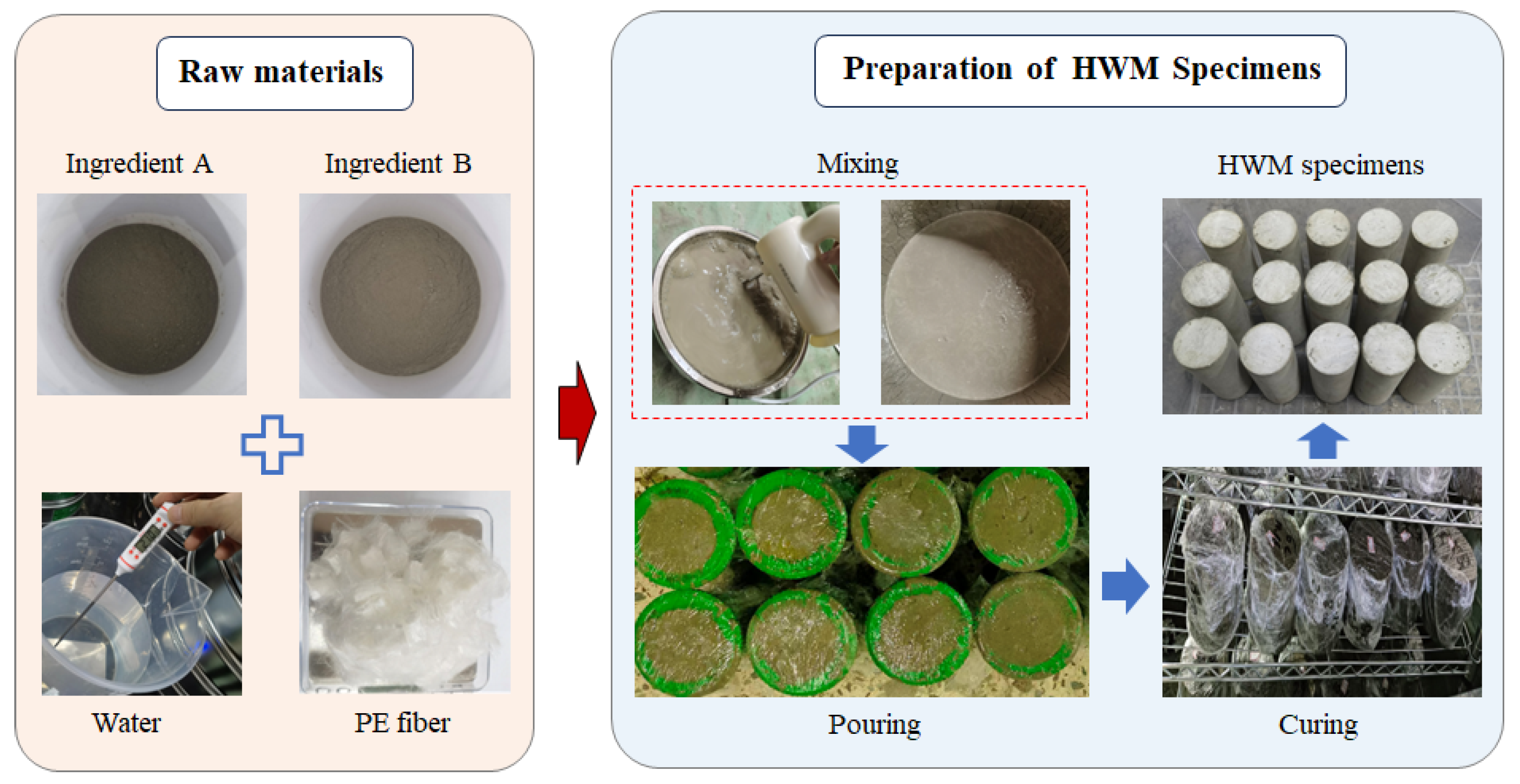
Before conducting the creep test, a series of cylindrical fiber-HWM mixture samples with a diameter of 50 mm and a height of 100 mm were prepared. The preparation process of PE fiber-modified HWM specimens is illustrated in Figure 2, and the detailed procedures are as follows. Specifically, considering that the distribution of fibers within the matrix is influenced by both the initial state of the fibers and the sample preparation process, any agglomerated fibers were first dispersed through manual manipulation. Subsequently, the pre-dispersed PE fibers were gradually added at a constant rate to equal masses of ingredient A and ingredient B, respectively. Each mixture was then dry blended at a low speed in a small-scale mixer for 120 s to ensure uniform fiber dispersion and prevent agglomeration. Subsequently, a precisely measured quantity of water was added to each dry blend, and the blends were individually stirred for 60 s using a handheld electric mixer to form uniform slurries. The two slurries were then combined and stirred for an additional 90 s. The resulting blended slurry was poured into molds to prepare standard specimens. After curing for 3 h, the specimens were demolded, wrapped with sealing film, and moved into a curing chamber maintained at 22 °C and a relative humidity above 95% for 28 d. Prior to testing, both loading surfaces of the specimens were ground flat using a grinding machine to ensure a surface unevenness of less than 0.05 mm.

2.2. Test Scheme and Equipment

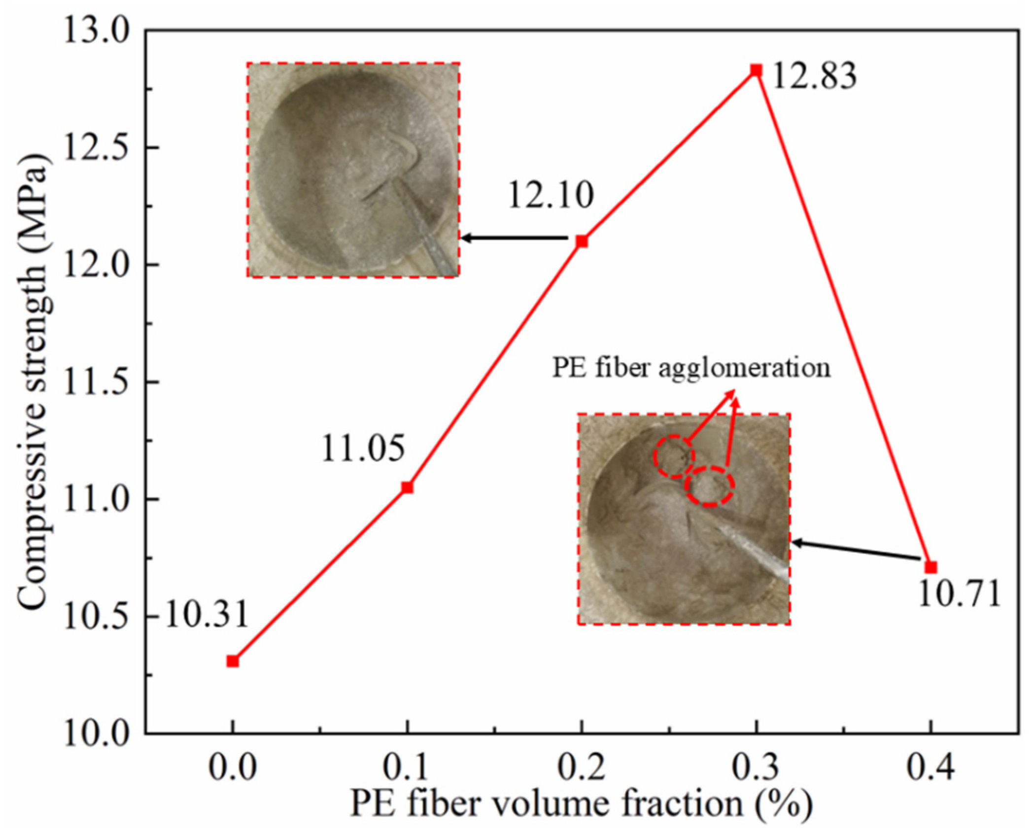
To investigate the instantaneous and long-term strength characteristics of modified HWM, uniaxial compression tests and multi-stage loading creep tests were conducted on specimens cured for 28 days. The uniaxial compression tests were displacement-controlled, and the loading rate was set at 3 mm/min. Each test group was composed of three specimens, and the obtained strength parameters are listed in Table 3. The test results showed that the standard deviation of the uniaxial compressive strength of each group of HWM specimens ranged from 0.14 to 0.36, indicating a low degree of data dispersion and demonstrating good consistency in specimen preparation. Figure 3 illustrates the evolution curve of the average compressive strength of HWM with respect to fiber content. It can be observed that as the fiber content increases, the uniaxial compressive strength of the specimens first experiences a linear growth phase and then undergoes a rapid decline phase, with an “inflection point” occurring at a fiber content of 0.3%. The appropriate incorporation of PE fiber enables their uniform dispersion to form a three-dimensional network within the matrix, which improves the stress distribution and inhibits microcrack initiation, thereby enhancing the compressive strength. However, a decrease in compressive strength was observed at a fiber content of 0.4%. The decrease in compressive strength is primarily attributed to the following factors: the higher fiber dosage increases the viscosity of the slurry and the density of the fiber network structure, which hinders the escape of air bubbles during mixing and vibration, and tends to introduce more micro-pores at the fiber–matrix interface zone. Additionally, the increased specific surface area of the fibers imposes higher demands on the quality of the interfacial transition zone, which under practical processing conditions can easily lead to insufficient encapsulation of the fibers by the cement paste, resulting in weakened physical bonding at the interface. Although a small number of visible fiber clumps were observed in the specimens, indicating generally acceptable macroscopic dispersion, the reduction in strength is primarily attributed to the cumulative effect of the aforementioned micro-defects and the overall weakening of the interfacial region, rather than being dominated by macroscopic agglomeration.
The creep test using the multi-stage loading method was conducted to investigate the time-dependent behavior of PE fiber-reinforced HWM under various stress levels. Based on the average peak strength of specimens with different PE fiber volume fractions, seven creep stress levels were determined, as listed in Table 4. The creep loading rate was maintained at a constant value of 3 mm/min, which was consistent with that in the uniaxial compression tests. Throughout the creep tests, the ambient temperature was kept within the range of 23 ± 2 °C by utilizing an air-conditioning system to ensure a stable environment and minimize the influence of temperature fluctuations on the creep results.
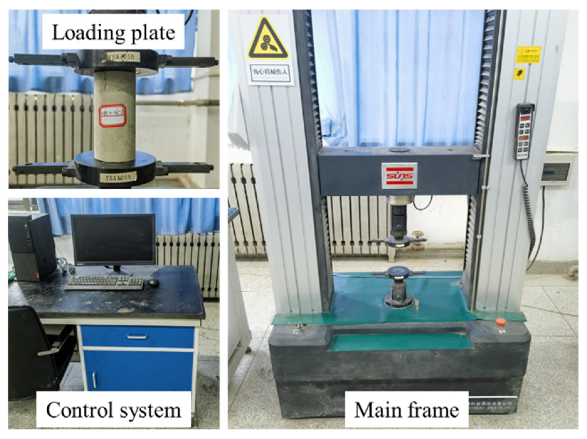
The mechanical tests in this study were conducted using an electronic universal testing system, as illustrated in Figure 4. This system is equipped with a high-precision load cell with a maximum capacity of 100 kN and supports multiple control modes, including displacement, velocity, and strain control, to meet the requirements of different testing standards. It also integrates a high-precision displacement sensor and is connected to a dedicated computer system for real-time data acquisition, processing, and automatic storage during testing.

2.3. Result Analysis of Creep Test

2.3.1. Deformation Characteristics

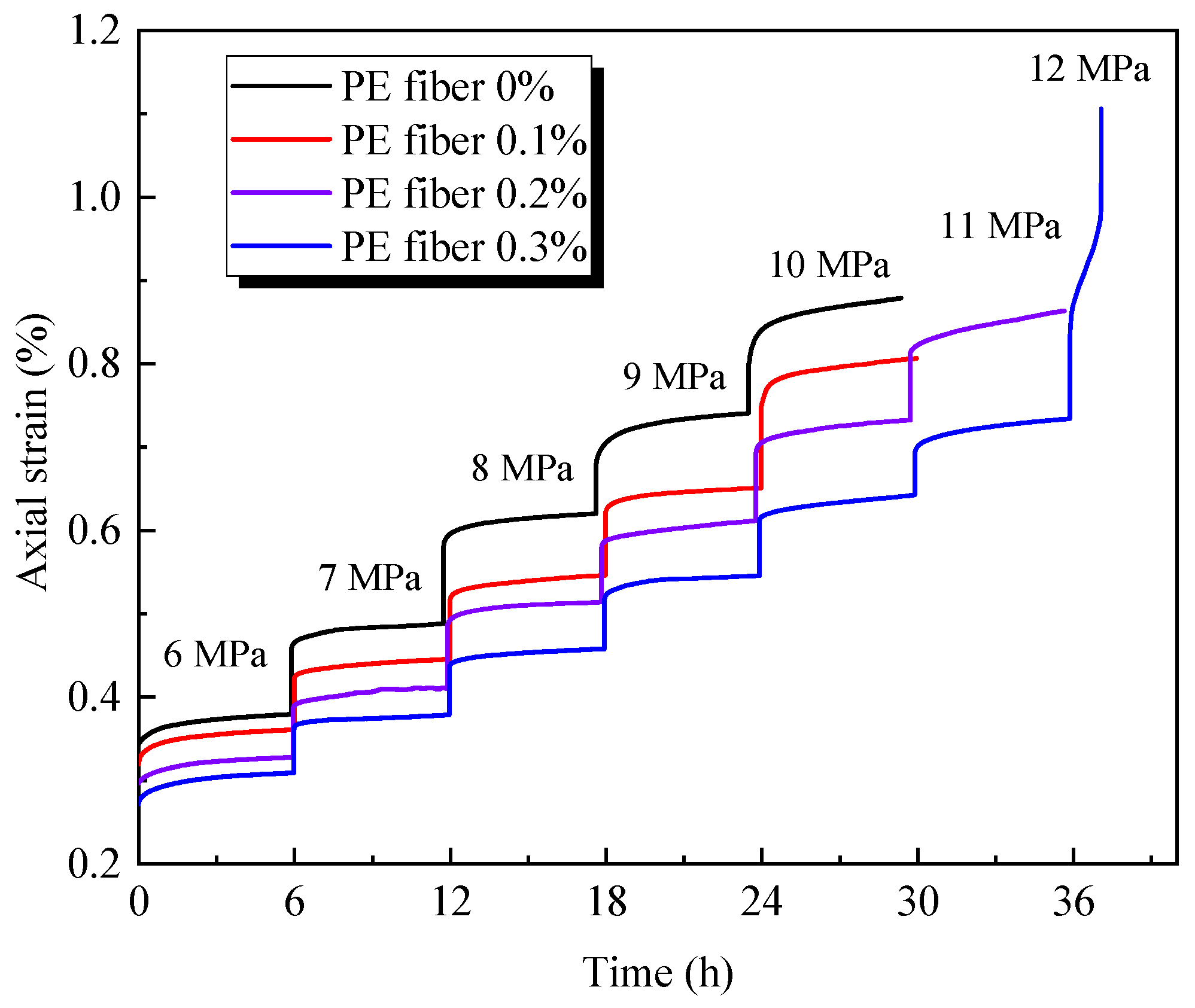
Uniaxial multi-stage loading creep tests were conducted on modified HWM with different PE fiber contents, and the curves of axial strain versus time were obtained as shown in Figure 5. It can be observed from Figure 5 that, under constant load, the total deformation of the specimens consists of instantaneous deformation and time-dependent deformation. The instantaneous deformation occurs at the moment of load application, and its magnitude is closely related to the applied stress level. Similarly, the evolution of time-dependent deformation is also affected by the stress level. At low stress levels, the deformation gradually diminishes over time and ultimately stabilizes. In contrast, at high stress levels, the time-dependent deformation exhibits nonlinear attenuation in the initial stage, followed by a nearly constant deformation rate in the later stage, which demonstrates a linear growth characteristic typical of steady-state creep. Overall, at the same stress level, the total axial deformation of the specimens exhibits a decreasing trend as the PE fiber content increases. Moreover, this deformation-inhibiting effect becomes more prominent as the stress level increases, indicating that the addition of PE fiber can effectively control the creep behavior of HWM. Notably, due to the limited duration of the creep tests, among the four types of specimens with different PE fiber contents, only the specimen with 0.3% PE fiber content exhibited the three-stage creep characteristic of “decaying creep—steady-state creep—accelerated creep”. The remaining specimens failed during the application of the next stress level and did not exhibit the accelerated creep stage.
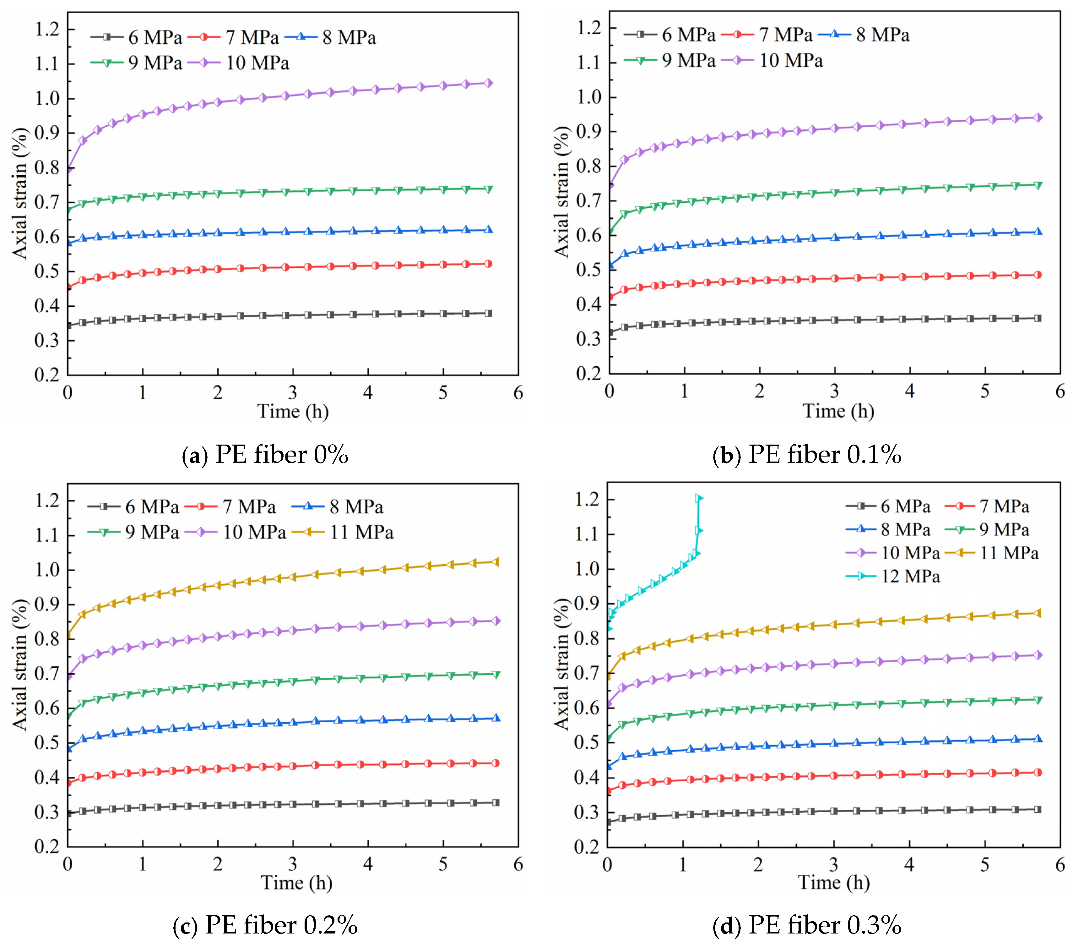
The multi-stage loading method serves as an efficient creep testing technique, enabling the rapid acquisition of creep responses of materials under various stress levels. However, the strain–time curves (such as Figure 5) obtained directly from this method represent the combined effect of multi-level stress histories and cannot reflect the creep behavior of materials under a single stress level. To address this, the Boltzmann superposition principle was applied to process the curves shown in Figure 5, and the creep curves of HWM specimens under different stress levels were obtained, as shown in Figure 6. As can be observed from Figure 6, the creep characteristics of the HWM are similar to those of rock-like materials, exhibiting a significant dependence on the stress level. When the stress level is low (less than the long-term strength), the specimen only shows decaying creep characteristics, where deformation increases nonlinearly with time and then stabilizes. When the stress level is high (exceeding the long-term strength), the creep curves demonstrate unstable deformation characteristics, entering a steady-state creep phase with a constant strain rate after decaying creep. Furthermore, once the total strain accumulates to a specific threshold, an accelerated creep stage ensues with a rapid nonlinear increase in strain rate, and the specimen eventually fails as damage continues to accumulate.
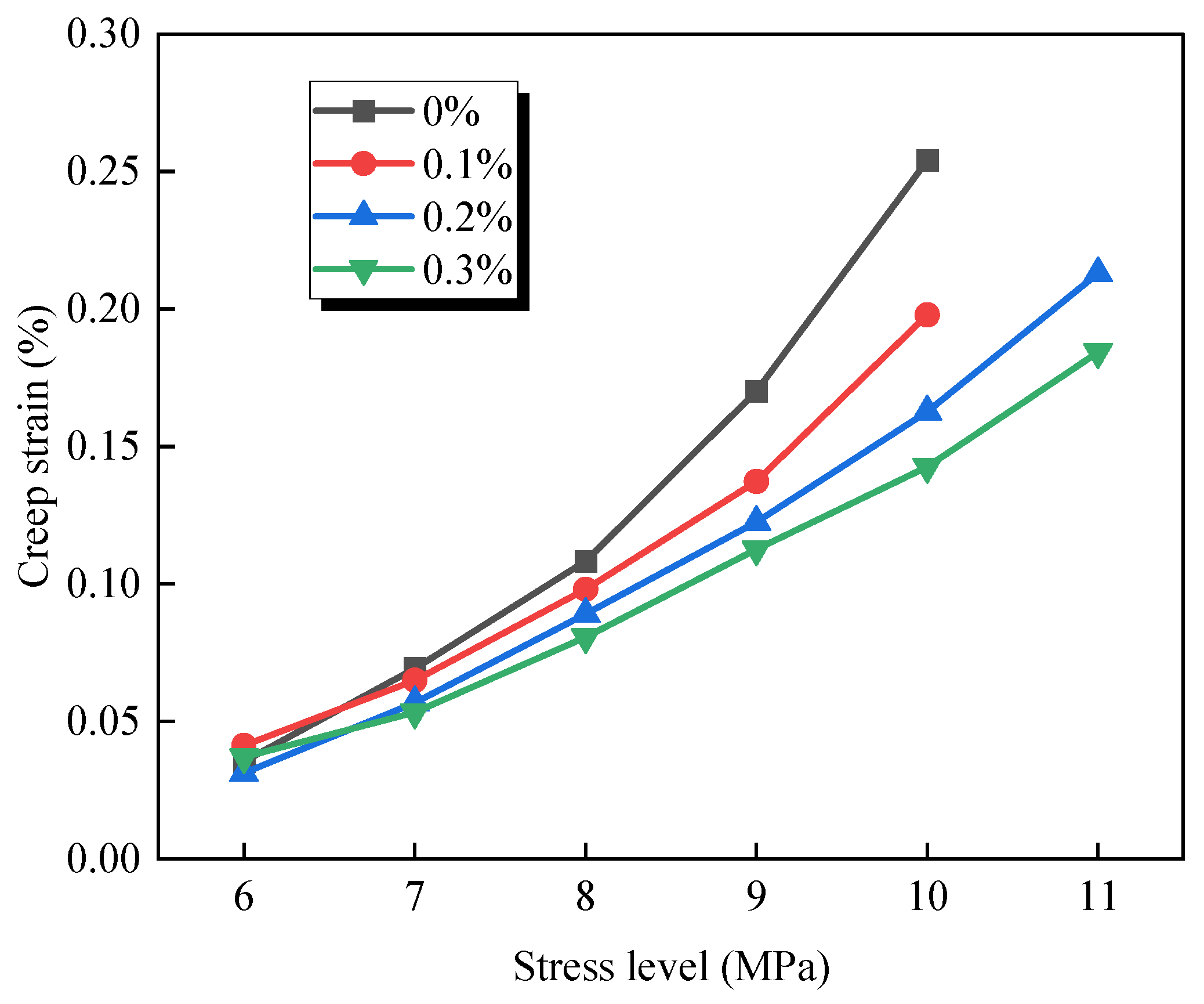
Studying the correlation between creep strain and stress level of HWM is a crucial foundation for evaluating the long-term stability of GER filling body under complex stress environments and holds significant importance for guiding the engineering design of such materials. Figure 7 illustrates the variation in creep strain with stress level for HWM with different PE fiber contents. Overall, the creep strain in all groups shows an increasing trend as stress levels increase, indicating that stress level is the key factor driving creep deformation in HWM. At the same stress level, the incorporation of PE fibers can effectively suppress the creep strain of HWM. For instance, under a stress level of 10 MPa and within the same time period, the creep strain of the non-fiber group is approximately 0.25%, while that of the group with 0.3% fiber content is 0.15%, representing a 40% reduction. This phenomenon can be attributed to the interfacial bonding effect between the PE fibers and the matrix. The fibers restrict the propagation and sliding of microcracks within the matrix through a bridging effect, thereby reducing the accumulation of creep deformation. Additionally, the inhibitory effect on time-dependent deformation gradually increased with increasing PE fiber content. Comparing the groups with 0.1%, 0.2%, and 0.3% fiber incorporation, the creep strain decreases sequentially, indicating a positive correlation between fiber content and creep resistance. However, it should be noted that when the stress level is below 8 MPa, the differences in creep strain among different fiber incorporation groups are relatively small, indicating that the reinforcing effect of fibers is not fully demonstrated in the low-stress range, whereas the “skeleton support” effect of fibers becomes more prominent under high-stress conditions.

2.3.2. Long-Term Strength

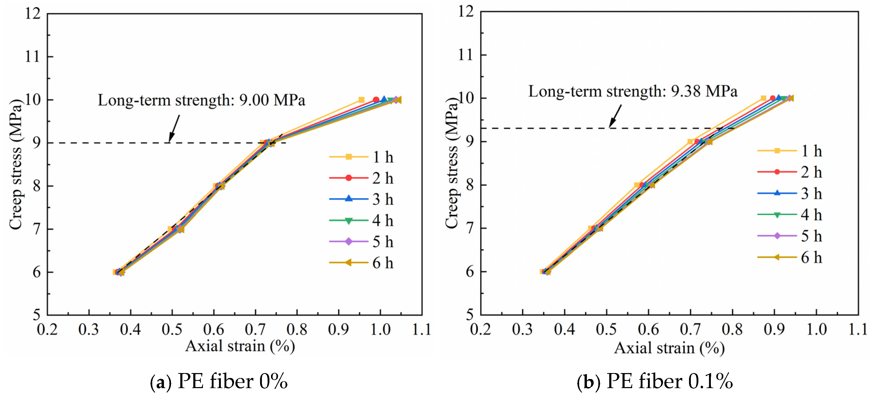
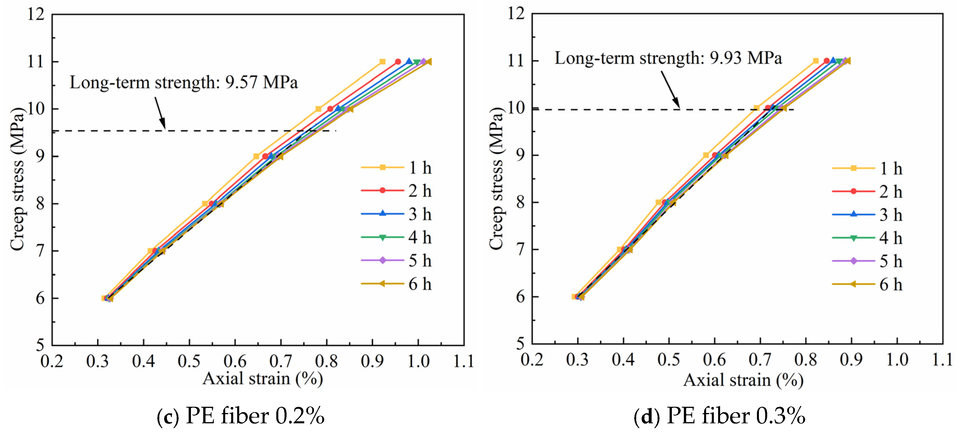
The long-term strength of a material is defined as the maximum stress that it can withstand under a constant load over an extended period without undergoing creep failure. When the creep stress exceeds this threshold, the material enters an unstable creep phase, where viscoplastic deformation accumulates continuously and ultimately leads to creep failure. Therefore, accurately determining the long-term strength of PE fiber-modified HWM is essential for evaluating the long-term stability of backfilling body in GER engineering. Methods for determining long-term strength include the isochronous stress–strain curve method, unstable creep method, and volumetric dilatancy method. Given that the creep characteristics of PE fiber-modified HWM are similar to those of rock materials, this study adopts the isochronous stress–strain curve method commonly used in the field of rock mechanics to determine the long-term strength of HWM. This method is based on multi-stage loading creep tests and involves constructing a curve representing the relationship between stress and strain at the same duration, identifying the inflection point where the curve transitions from linear to nonlinear. The stress at the inflection point is identified as the long-term strength. Figure 8 presents the isochronous stress–strain curves of HWM with varying PE fiber contents at 1 h intervals.
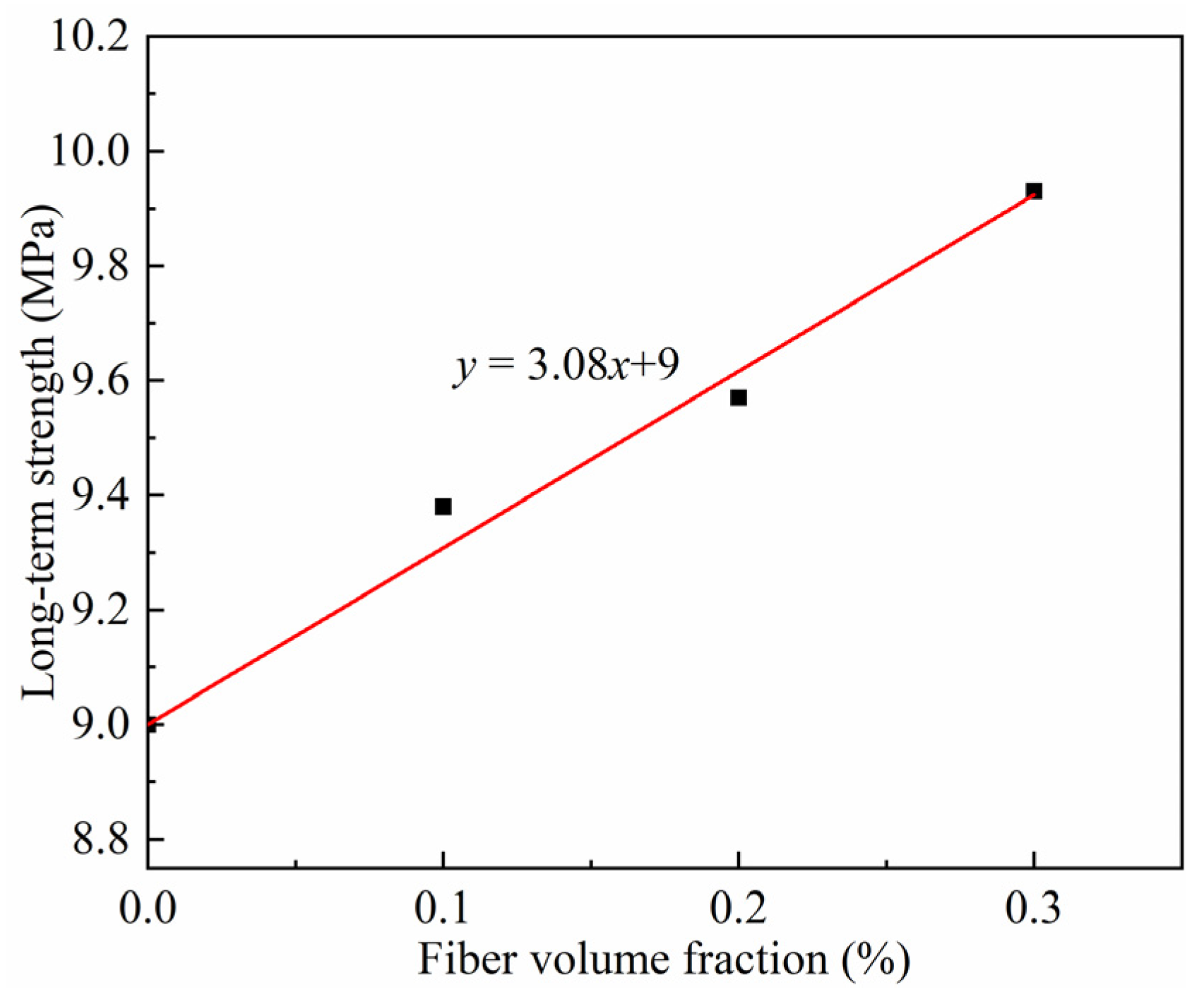
From Figure 8, it can be found that the long-term strengths of HWM specimens with PE fiber volume fractions of 0%, 0.1%, 0.2%, and 0.3% are 9 MPa, 9.38 MPa, 9.57 MPa, and 9.93 MPa, respectively. To further verify the reliability of the long-term strength of HWM with different PE fiber contents obtained by the isochronous stress–strain curve method, the steady-state creep discrimination method was employed to identify the long-term strength of HWM specimens based on the creep curves. When applying the steady-state creep discrimination method to estimate the long-term strength, the long-term strength is defined as the maximum applied stress that can sustain a zero steady-state creep strain rate. Based on the creep curves (Figure 6), steady-state creep behavior is observed within the applied stress range of 9 MPa to 10 MPa. This consistency indicates that the long-term strength derived from the isochronous curve method is sufficiently reliable. Figure 9 illustrates the relationship between the long-term strength of the modified HWM and the volume fraction of PE fibers. The results indicate that when the fiber volume fraction is below 0.3%, the long-term strength of the material exhibits a linear growth trend with increasing fiber content, with a fitting correlation coefficient of 0.98. Specifically, the long-term strength of the modified HWM with 0.3% PE fiber content is approximately 10.3% higher than that of the pure HWM without fiber. This phenomenon suggests that the appropriate incorporation of fibers can optimize the stress transfer pathways within the matrix, effectively suppress the initiation and propagation of microcracks, and thereby significantly enhance the critical stress level at which the material maintains structural integrity under long-term constant load.

2.3.3. Creep Failure Time and Failure Mode

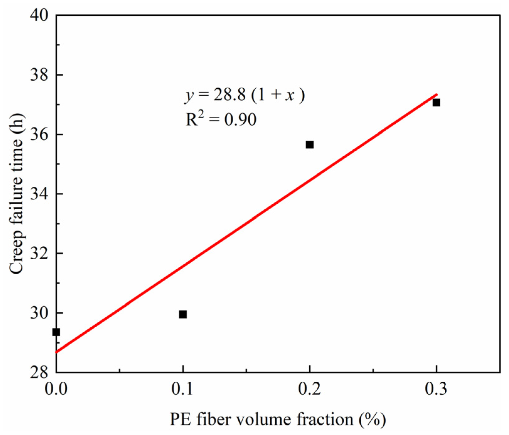
The creep failure time is defined as the duration from the initial deformation to the final failure of a material under sustained load. In comparison with short-term strength parameters, this index reveals the delayed failure characteristics of materials under stress levels lower than their instantaneous strength, which results from the gradual and continuous accumulation of internal damage over time. For engineering structures subjected to long-term static loads, such as mine backfills, the creep failure time is a key indicator for assessing the risk of progressive instability during service. Figure 10 illustrates the variation in creep failure time of HWM with the volume fraction of PE fibers. The results show a significant linear positive correlation: as the PE fiber content increases from 0% to 0.3%, the creep failure time extends from 29.36 h to 37.07 h, and the stress level at which creep failure occurs also increases accordingly. This indicates that an appropriate amount of PE fibers can significantly enhance the long-term creep resistance of HWM. These findings provide theoretical support for optimizing the fiber content in HWM under long-term loading conditions. The improvement in performance is primarily attributed to the crack-bridging and stress-transfer mechanism of the PE fibers. Specifically, under sustained loading, the fibers effectively bridge the tips of microcracks through mechanical interlocking and interfacial friction with the matrix, thereby restraining further crack propagation. Meanwhile, the uniform distribution of fibers within the matrix helps to transfer loads from localized stress concentration zones to the surrounding matrix, which slows down the damage accumulation process and ultimately leads to a notable extension of the creep failure time.
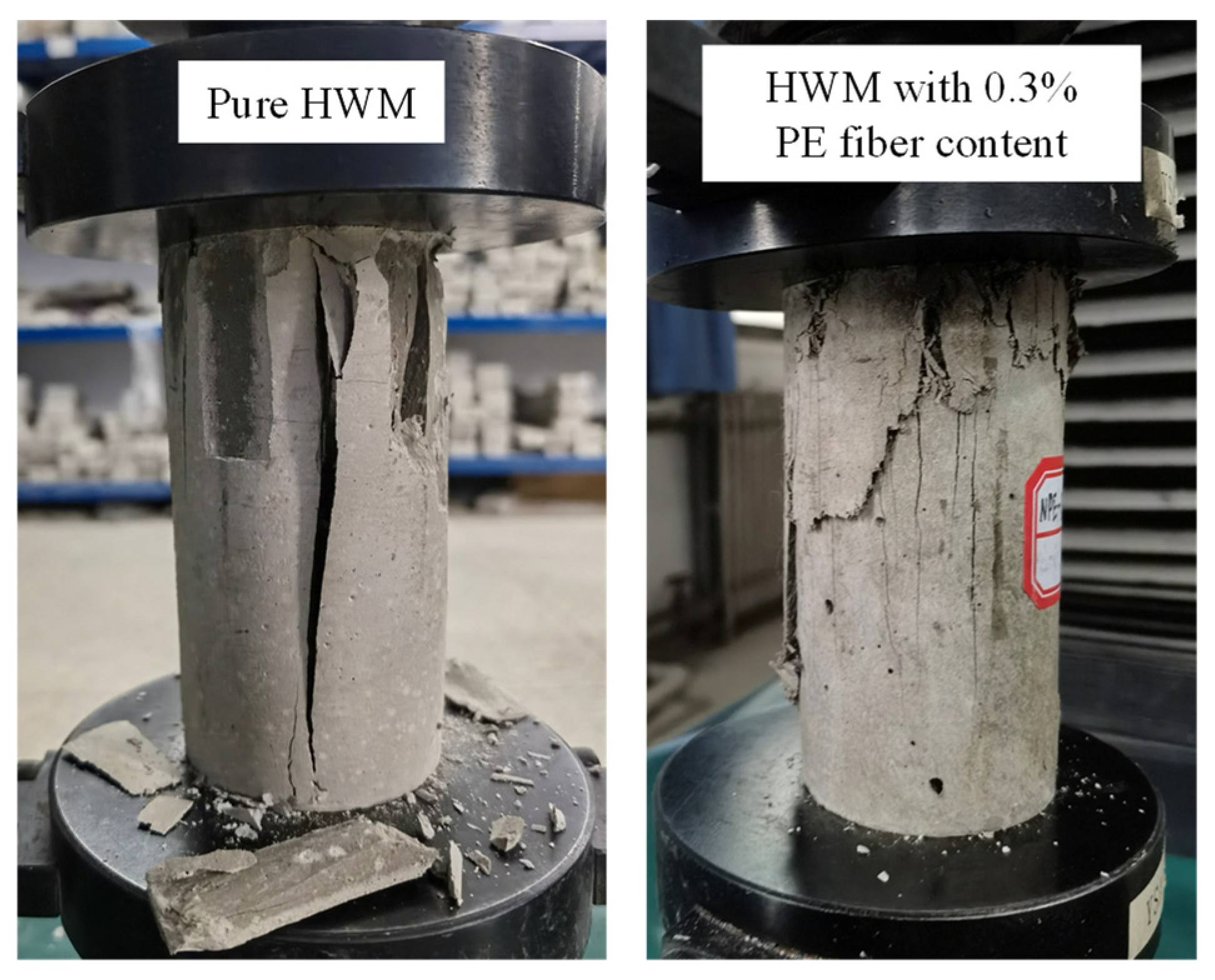
Figure 11 illustrates the creep failure characteristics of pure HWM specimens and HWM specimens with a 0.3% PE fiber content. The pure HWM specimen exhibits typical brittle failure features: after failure, the specimen fractures into several large pieces with a limited number of cracks, presenting a splitting–disintegration failure mode. In contrast, the specimen incorporating 0.3% PE fibers demonstrates enhanced toughness characteristics. Its failure process is accompanied by the development of multiple fine and dispersed longitudinal microcracks, which gradually propagate and interconnect to eventually form the main fracture surface. After failure, the fiber-reinforced specimen retains a generally intact structural outline without undergoing complete disintegration. The difference in failure modes between the two types of specimens indicates that the addition of PE fibers effectively suppresses localized crack propagation, disperses damage through multiple microcracks, and thereby shifts the material’s failure behavior from brittle to quasi-brittle or more ductile. The bridging and interlocking effects provided by the fibers after matrix cracking are the main reasons for the relatively preserved structural integrity of the specimen after failure.

3. Fractional-Order Creep Model for PE Fiber-Reinforced HWM

3.1. Fractional-Order Dashpot

Fractional calculus, an extension of integer-order calculus, exhibits distinct advantages in describing complex systems characterized by memory effects, nonlocality, and other features. It has been extensively applied in multiple fields, including physics [30], engineering [31,32], and finance [33]. In the process of its development, researchers have proposed several definitions of fractional derivatives. Among them, the Grünwald–Letnikov (G–L), Riemann–Liouville (R–L), and Caputo definitions are the most commonly used. Owing to its concise form, ease of theoretical derivation, and numerical implementation, the R–L fractional derivative has been widely adopted in the establishment of creep constitutive models. Its integral expression is as follows:
I t α a   f t = 1 Γ α a t t τ α 1 f τ d τ
After a mathematical transformation, the differential equation in Equation (2) can be expressed as:
D t α a RL   f t = d n d t n I t n α a   f t = 1 Γ n α d n d t n a t f τ t τ α n + 1 d τ
where I t α a and D t α a RL represent fractional-order integral and differential operators, respectively; α is the fractional-order number; t represents time; Γ is the Gamma function, also known as the Euler integral of the second kind, Γ z = 0 t z 1 e t d t .
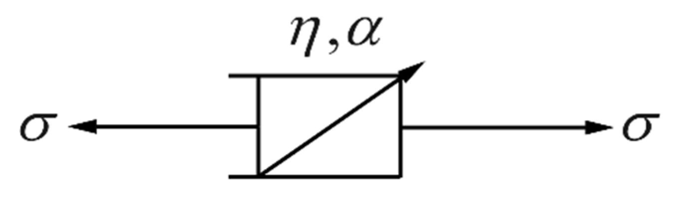
In the field of rheology, Scott Blair proposed the fractional-order dashpot element based on R-L fractional calculus and derived its constitutive equation [34], as shown in Equation (4). This element is also known as the Abel dashpot, and its model schematic is shown in Figure 12.
σ t = η d α ε t d t α       0 α 1
where η is the viscosity coefficient of the Abel dashpot.
When the stress in Equation (4) remains constant, the creep equation of the Abel dashpot can be derived by applying the R-L fractional integral, and its expression is as follows:
ε t = σ η t α Γ α + 1       0 α 1
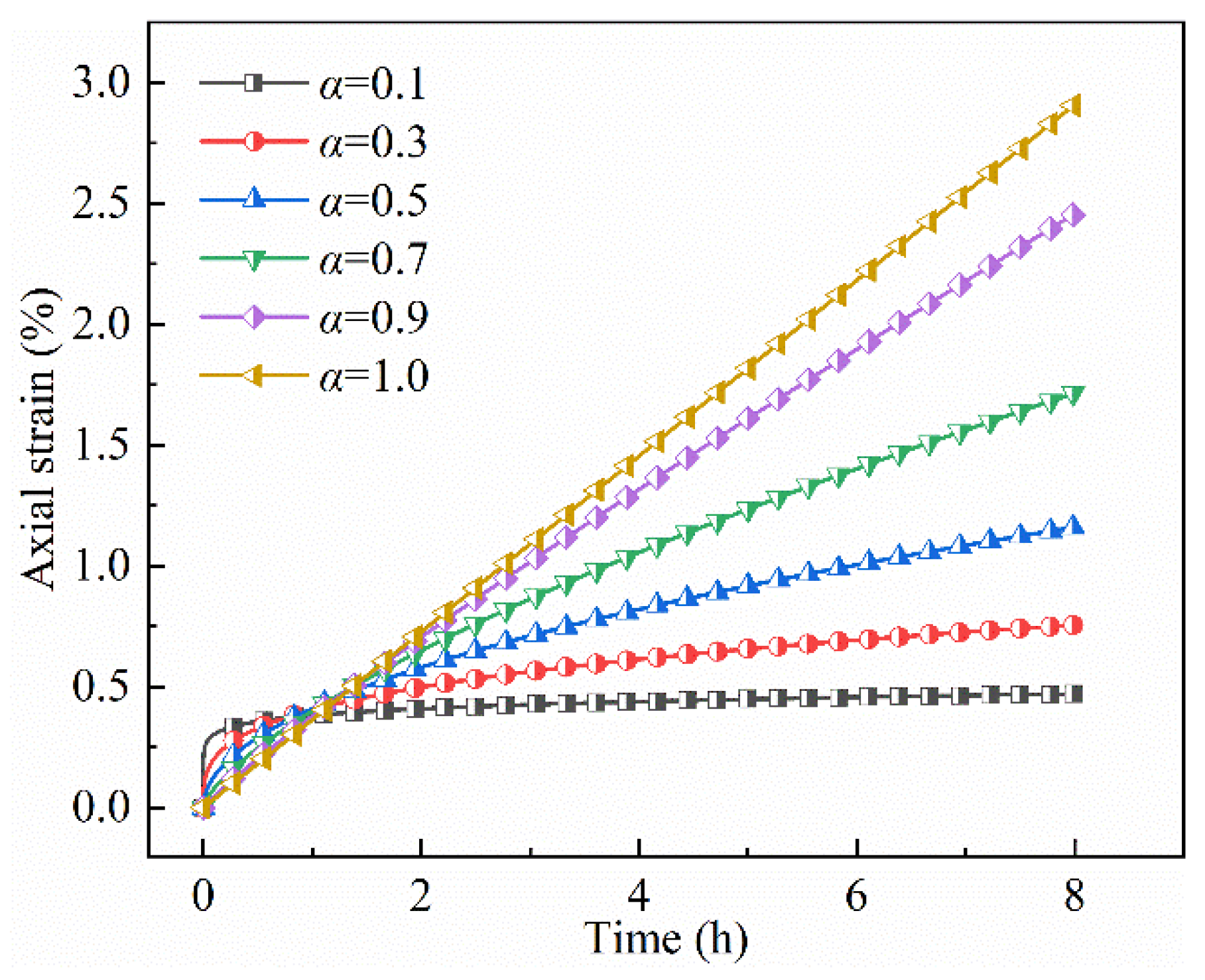
To clarify the characteristics of the Abel dashpot in depicting the creep behavior of materials, creep curves corresponding to different fractional orders α were plotted under a stress level of 8 MPa and a viscous coefficient of 22 GPa·h, as shown in Figure 13. It is evident that when 0 < α < 1, the strain gradually increases over time, and the curve shape gradually approaches linearity as α increases. At α = 1, the strain-time curve exhibits a typical linear relationship, at which point the component is equivalent to the Newtonian dashpot. The above results suggest that by adjusting the fractional order α, the Abel dashpot can continuously and effectively characterize the time-dependent deformation behaviors ranging from nonlinear creep to linear viscous flow.

3.2. Fractional Viscoplastic Component

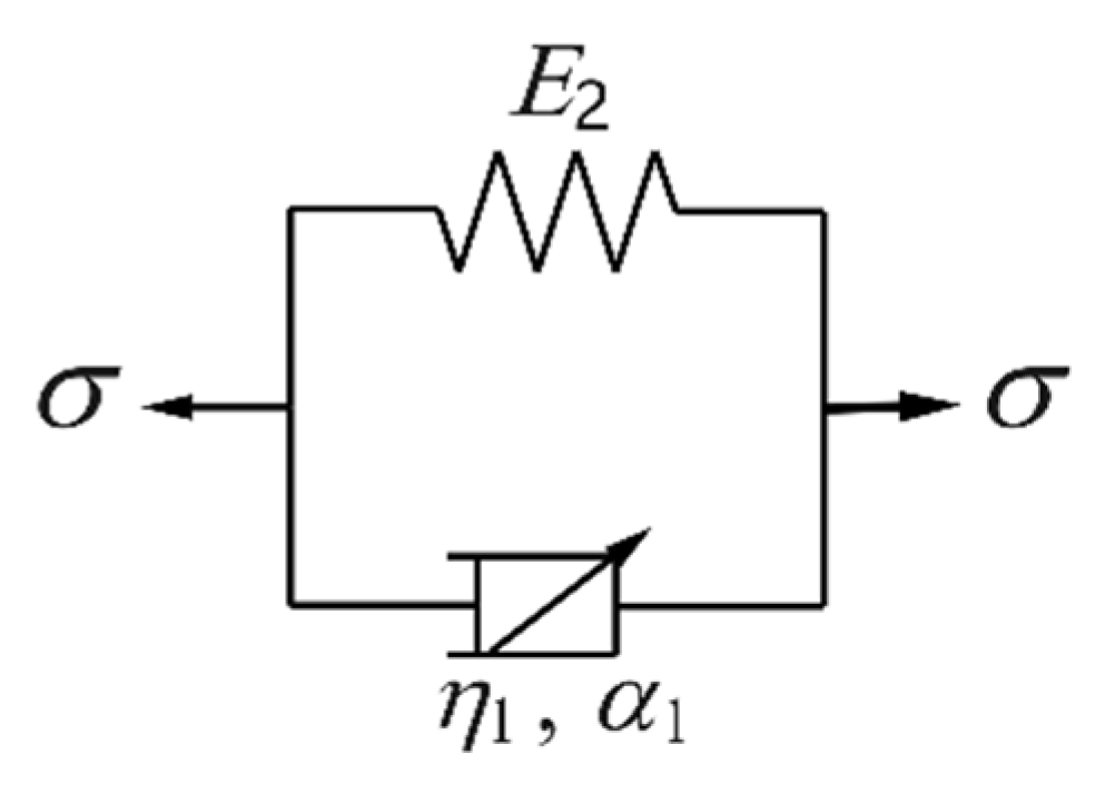
According to the creep curves of PE fiber-modified HWM (Figure 6), when the creep stress level is lower than the long-term strength, the specimen experiences instantaneous deformation after loading, followed by a decaying creep stage where the strain rate gradually decreases and ultimately approaches zero. The strain curve at this stage shows distinct nonlinear characteristics, and the creep behavior is jointly affected by both the stress level and fiber content. The classical Kelvin model, with its parameters being constants and independent of time, is unable to accurately describe the aforementioned creep process. Hence, by taking into account the time-dependent viscosity coefficient, this study establishes a nonlinear viscoelastic model based on the Abel dashpot, as shown in Figure 14. This viscoelastic model is composed of a Hookean spring connected in parallel with an Abel dashpot. Based on the rules for series and parallel connections of mechanical elements, the constitutive equation can be derived as follows:
σ = E 2 ε ve + η 1 d α 1 ε ve d t α 1
where σ represents the stress, εve denotes the viscoelastic strain, E2 and η1 are the elastic modulus and viscous coefficient of the viscoelastic model, respectively, and α1 is the fractional order in the viscoelastic model.
In the process of deriving the creep equation, the Mittag-Leffler function and the inverse Laplace transform of the two-parameter Mittag-Leffler function are required. Their definitions are as follows:
E α , β ( z ) = k = 0 z k Γ α k + β       ( α > 0 ,   β > 0 )
0 e s t t k + β 1 E α , β ( k ) ± a t α d t = k ! s α β ( s α a ) k + 1           ( Re ( s ) > a 1 / α )
where α, β, and k represent the parameters of the Mittag-Leffler function. The creep equation of the fractional-order viscoelastic model is as follows:
ε ve = σ η 1 t α 1 E α 1 , α 1 + 1 E 2 η 1 t α 1

3.3. Fractional Viscoplastic Component Considering PE Fiber Content

When the stress level exceeds the long-term strength, the PE fiber-modified HWM specimen enters the steady-state creep stage after going through the decaying creep stage. At this stage, even though microcrack propagation and plastic strain accumulation have taken place within the specimen, their weakening effect on the overall load-bearing capacity of the material is not substantial. Hence, some studies suggest that creep damage during this stage is not prominent, and its evolution can be neglected in the establishment of creep models [35]. Furthermore, creep test results indicate that the strain rate during the steady-state creep stage varies significantly under different stress levels, with higher stress levels leading to greater steady-state creep rates. Existing studies have pointed out that the viscous coefficient of the material depends on the stress level, which is the primary reason for the differences in steady-state creep rates under different stress conditions [36,37]. In this study, considering the stress dependence of the viscous coefficient during the steady-state creep stage, it is assumed that the viscous coefficient has a negative power function relationship with the stress level, which can be expressed as:
η = η 2 e λ
where η2 is the initial viscosity coefficient, and λ is the viscosity coefficient control parameter related to the stress level.
The test results presented in Section 2 indicate that once the specimen enters the steady-state creep stage, it gradually progresses into the accelerated creep stage over time and eventually fails. Previous studies have demonstrated that accelerated creep in rock-like materials is often associated with a strain threshold [38]. Specifically, when the total strain exceeds this threshold, the deformation transitions from steady-state creep to accelerated creep. During the accelerated creep stage, the internal damage of the specimen accumulates rapidly, resulting in a substantial reduction in its load-bearing capacity [39]. Given that the influence of damage on creep can no longer be ignored at this stage, a non-constant viscosity coefficient described by a damage factor was introduced to characterize the viscous deformation of HWM.
η D = η 0 ( 1 D )
where η0 and D represent the initial viscosity and the damage variable (ranging from 0 to 1), respectively.
Based on the Krajcinovic damage law [40], the damage evolution of HWM creep is defined as:
D = 1 exp γ t t *
where γ represents the material parameter, t denotes the creep time, and t* signifies the time at which the total strain reaches the threshold value ε*.
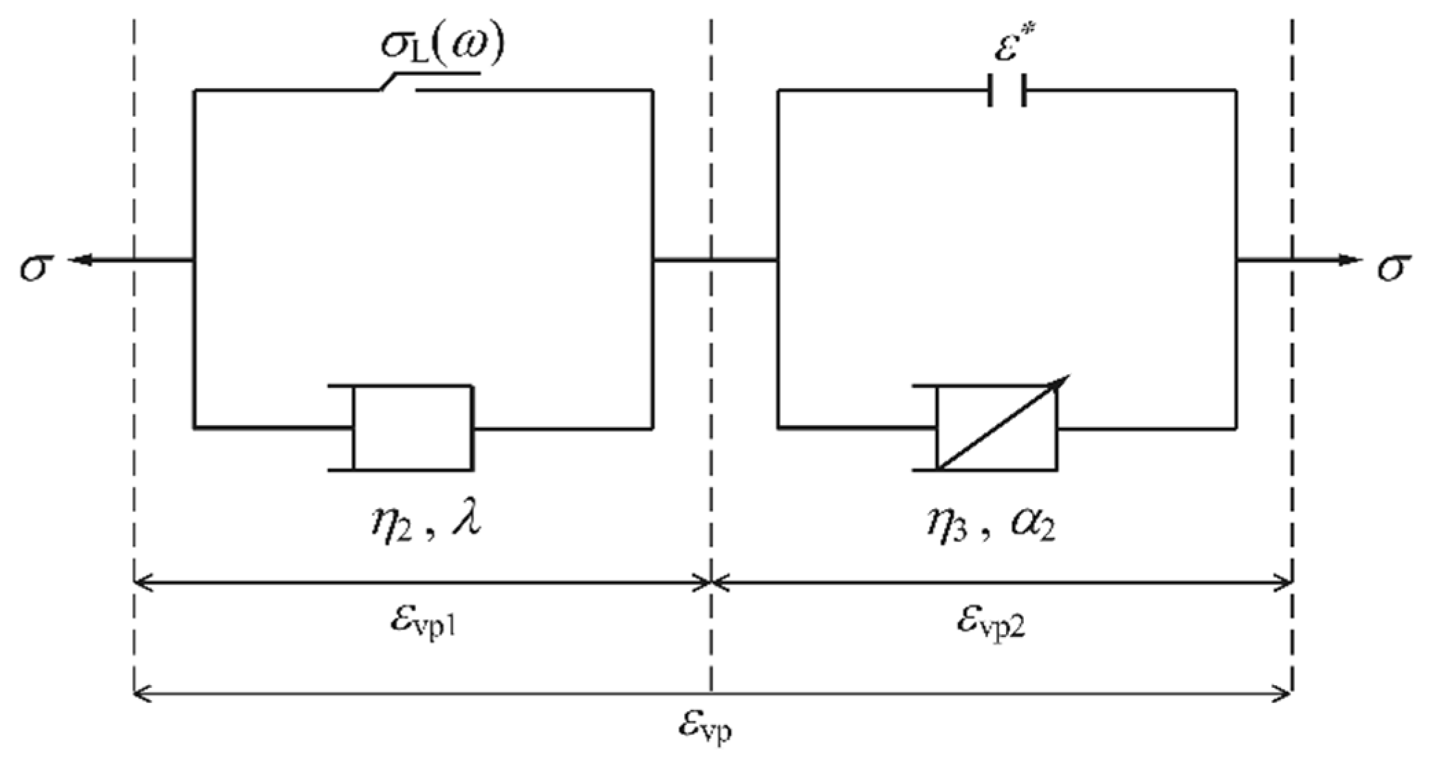
Furthermore, considering the influence of PE fiber volume fraction on the long-term strength of HWM, this study incorporates fiber content into the plastic element to construct an improved Saint-Venant body. To accurately describe the steady-state and accelerated creep behaviors of PE fiber-modified HWM under high stress levels, the improved Saint-Venant body is connected in parallel with a nonlinear viscous dashpot, which is then connected in series with a damage Abel dashpot that includes a strain threshold, thereby establishing a new viscoplastic damage model, as shown in Figure 15.
In summary, the creep equation of the fractional-order viscoplastic damage model is expressed as:
ε vp = σ σ L η 2 e λ t       σ σ L , ε < ε * σ σ L η 2 e λ t + σ η 3 t α 2 E 1 , α 2 + 1 γ t t * σ σ L , ε ε *
where σL represents the long-term strength of PE fiber-modified HWM, and η2 and η3 represent the viscous coefficients of the dashpots in the viscoplastic damage model, respectively.

3.4. Fractional-Order Viscoelastic-Plastic Damage Model

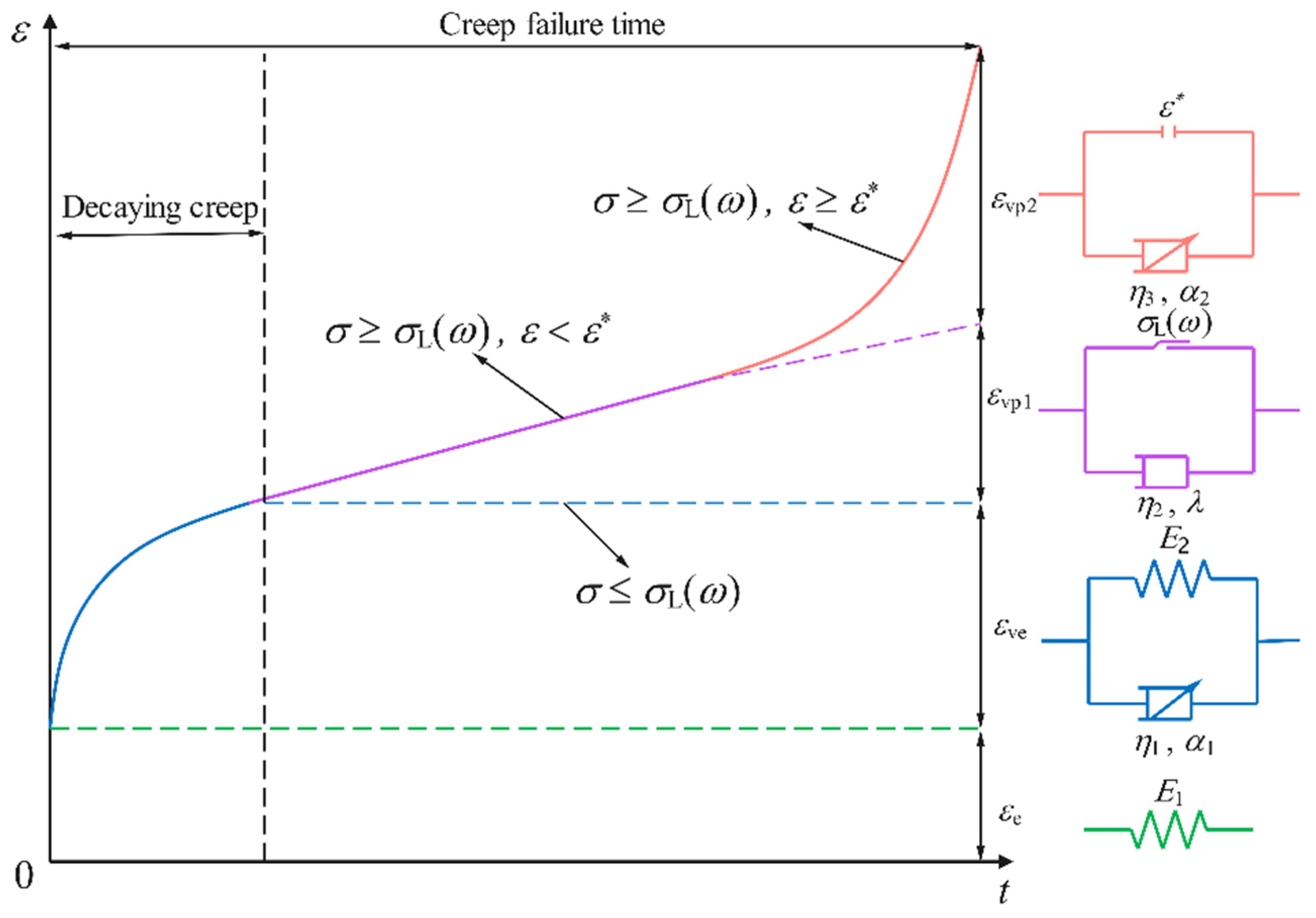
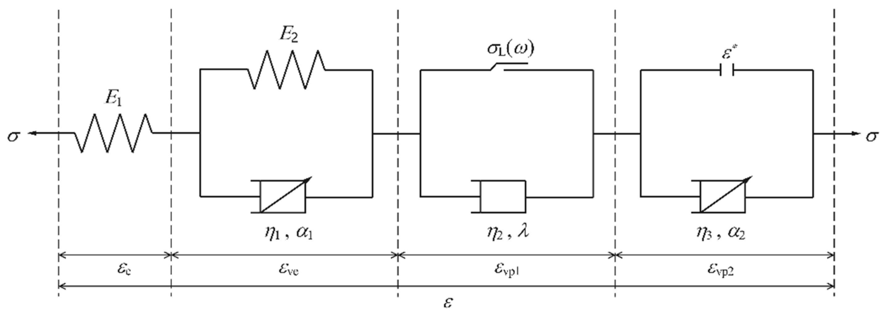
Figure 15 illustrates the creep curve characteristics of PE fiber-modified HWM under various stress levels. As shown in Figure 16, during the initial loading phase, HWM undergoes instantaneous strain. Due to the extremely short duration of loading compared to the subsequent creep process, this instantaneous deformation behavior can be characterized by a Hookean body. After the instantaneous deformation, the specimen enters the decaying creep stage, where the strain rate decreases nonlinearly with time. The time-dependent deformation in this stage can be described by a fractional-order Kelvin model. When the stress level exceeds the long-term strength of the material and the strain remains below the accelerated creep threshold, the specimen enters the steady-state creep stage, where strain increases approximately linearly with time. Once the strain exceeds the accelerated creep threshold, the material enters the accelerated creep stage. The time-dependent deformation characteristics of HWM in both the steady-state and accelerated creep stages can be described using a fractional viscoplastic damage model. Based on the above analysis, a fractional-order creep damage model for PE fiber-modified HWM is constructed using the rheological element combination method, as illustrated in Figure 17.
According to the superposition principle, the relationship between total stress and strain can be expressed as:
ε = ε e + ε v e + ε vp 1 + ε vp 2 σ = σ e = σ ve = σ vp 1 = σ vp 2
When creep stress is below the long-term strength ( σ < σ L ), the HWM only undergoes viscoelastic strain. The creep equation can be expressed as:
ε t = σ E 1 + σ η 1 t α 1 E α 1 , α 1 + 1 E 2 η 1 t α 1
If σ σ L , ε < ε * , then the creep equation is
ε t = σ E 1 + σ η 1 t α 1 E α 1 , α 1 + 1 E 2 η 1 t α 1 + σ σ L η 2 e λ t
If σ σ L , ε ε * , then the creep equation is
ε t = σ E 1 + σ η 1 t α 1 E α 1 , α 1 + 1 E 2 η 1 t α 1 + σ σ L η 2 e λ t + σ η 3 t α 2 E 1 , α 2 + 1 γ t t *

4. Verification of the Creep Model and Parameter Sensitivity Analysis

4.1. Verification of the Creep Model

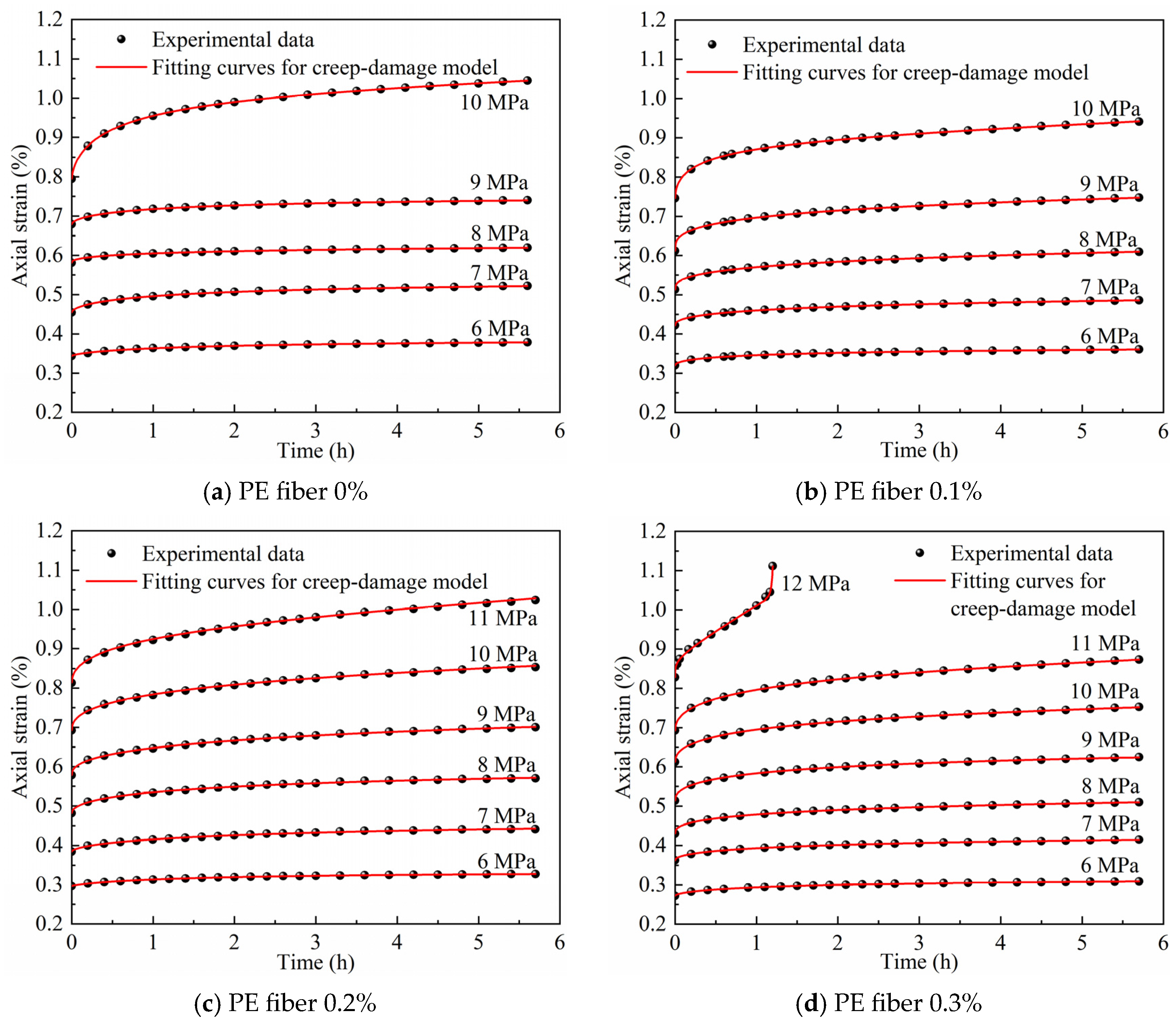
To validate the accuracy and practicality of the proposed creep model, the identification of model parameters was carried out based on creep test data of HWM with different PE fiber contents. Before fitting the creep parameters, it is necessary to determine the parameters related to the intrinsic material properties. Test results show that the long-term strength of HWM depends on the fiber volume fraction, following an approximately linear correlation. The long-term strength was first determined using the isochronous stress–strain curve method. Subsequently, by performing a linear fit between the long-term strength and the fiber content across different mix proportions, a parameter k = 3.0786 was derived. Then, the accelerated creep strain threshold for PE fiber-modified HWM specimens was determined based on creep curves exhibiting typical three-stage characteristics. Finally, based on Equations (15)–(17), the Levenberg–Marquardt nonlinear least squares algorithm built into Origin software version 2021 was employed to fit the creep curves and precisely invert the model parameters. The inversion results of the model parameters obtained from the creep curves are presented in Table 5. A comparison between the experimental creep data and the fitting results of the fractional-order creep model is shown in Figure 18.
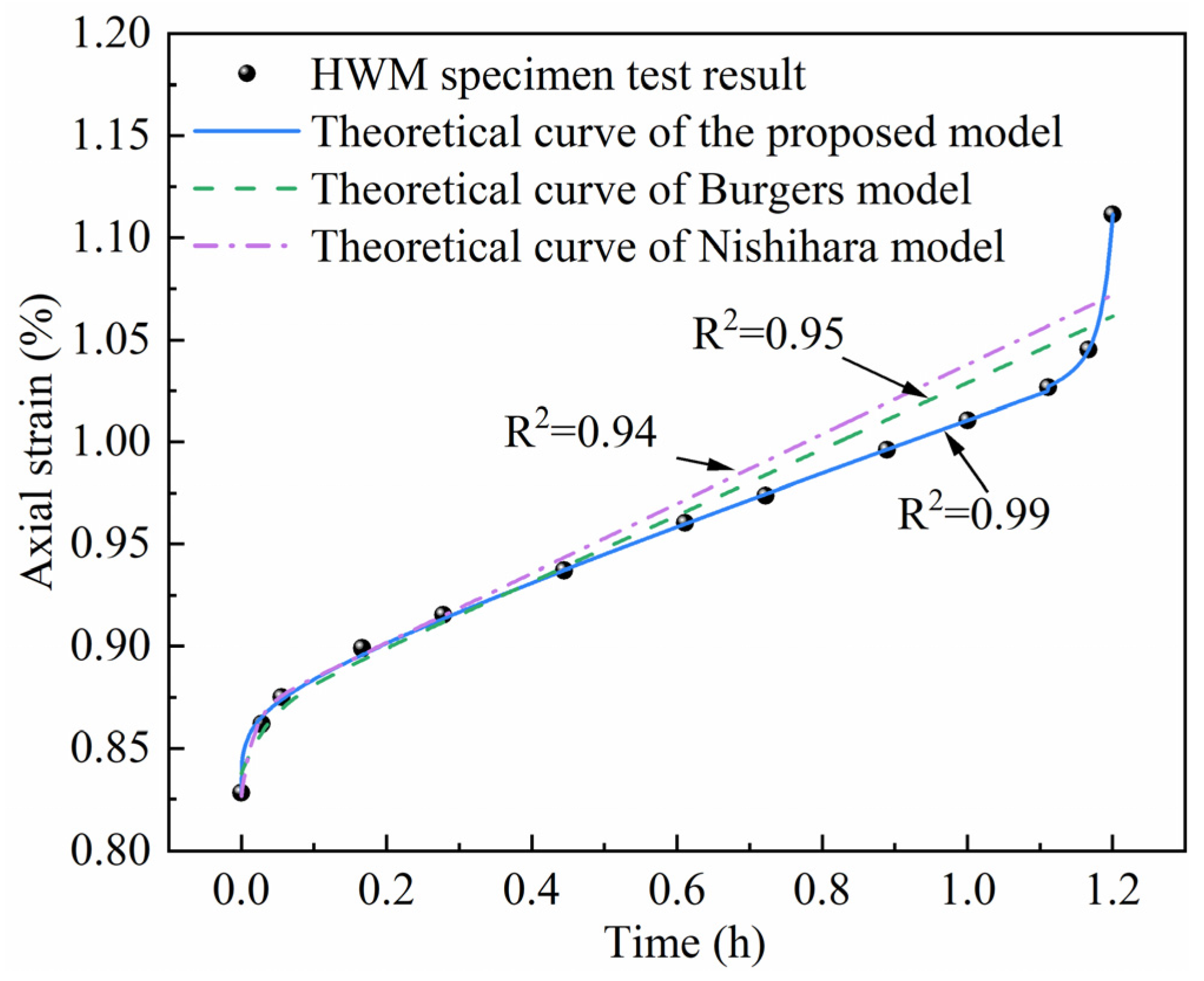
As shown in Figure 18, the experimental and theoretical curves exhibit a high degree of agreement under various stress levels, accurately capturing all stages of creep in PE fiber-modified HWM. The fitting correlation coefficients all exceed 0.98. Comparison of the proposed creep model with the classical creep model is shown in Figure 19. In the early creep phase, all three models show satisfactory alignment with the test data, suggesting their capability in describing the initial time-dependent deformation of PE fiber-reinforced HWM. As time proceeds, the predictions of the classical creep models diverge increasingly from the test data. Importantly, throughout the entire creep duration, and most notably in the late stages, the theoretical curve of the proposed model shows a significant agreement with the test data. This is further supported by the correlation coefficient. It can be inferred that the proposed viscoelastic-plastic damage creep model not only precisely describes the decaying and steady-state creep characteristics of PE fiber-modified HWM under low stress levels but also effectively represents the accelerated creep behavior and damage evolution under high stress conditions. These results demonstrate the strong applicability and reliability of the model in simulating the time-dependent mechanical behavior of PE fiber-modified HWM.
Additionally, it is important to note that in this study, both the experiments and the proposed model are established under uniaxial compression conditions. This experimental setup is mainly based on the actual loading characteristics of the backfill body in GER engineering. Specifically, the backfill body is adjacent to the mined-out area on one side and connected to the roadway on the other side, which leads to weak lateral constraints. As a result, it mainly bears the vertical load from the overlying strata and can be approximately considered to be in a uniaxial compression state. Therefore, the constitutive model proposed here is primarily applicable to scenarios dominated by uniaxial compression.
To enhance the engineering practicality of the creep constitutive model developed in this study, the determination of model parameters at the engineering scale is particularly crucial. Accordingly, a parameter determination method is proposed, which consists of establishing initial parameter estimates based on experimental data and then inversely verifying them with field monitoring data. First, considering the sensitivity of creep parameters to stress levels, the average values of the model parameters derived from inverse analysis under multi-stage stress levels (Table 5) are employed as the initial values for engineering applications. Second, based on the established relationship between fiber content and long-term strength (as shown in Figure 9), the long-term strength of HWM at a specific fiber content is determined. Subsequently, accessible monitoring data (such as displacement) from the early stages of an engineering project are employed in inverse analysis to calibrate the parameters. This ensures that the model predictions are consistent with specific engineering conditions.

4.2. Parametric Analysis of the Proposed Model

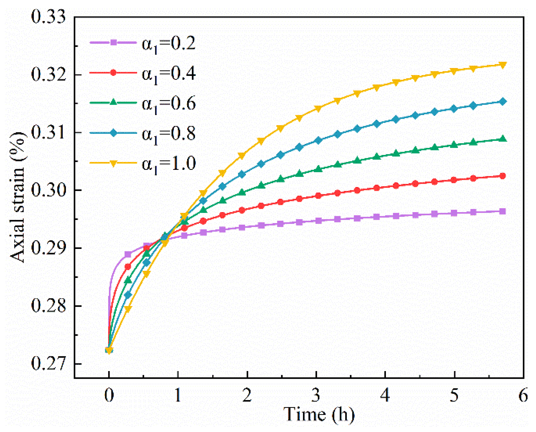
To clarify the physical significance of the introduced parameters, a sensitivity analysis was conducted for parameters α1, α2, λ, and γ in the model. Using the controlled variable method, each parameter was systematically varied while keeping the others fixed. The reference values for all other parameters corresponded to those obtained for PE fiber-modified HWM with a fiber volume fraction of 0.3%, as listed in Table 6.
Figure 20 presents the creep curves corresponding to different fractional orders α1 under a stress level of 6 MPa. The results indicate that α1 plays a significant role in regulating morphology and evolution of the decaying creep curve. As α1 increases, the strain decay rate during the initial creep phase gradually decreases, while the slope of the curve in the later stage increases accordingly. This behavior is attributed to the moderating effect of the fractional order on the material’s memory: a smaller α1 reduces the material’s dependence on historical strain, weakens the nonlocal characteristics of early creep behavior, and thereby accelerates strain attenuation. The variation in the decay gradient of the strain curve is most pronounced when α1 increases from 0.6 to 0.8, indicating that within this range, even slight adjustments in α1 can significantly alter the viscoelastic response of the material. Consequently, the accuracy of the model in predicting creep behavior within this parameter range highly depends on the precise calibration of α1. This further confirms that α1 is a key parameter in the fractional damage creep model, as its value directly determines the rate and overall magnitude of strain decay.
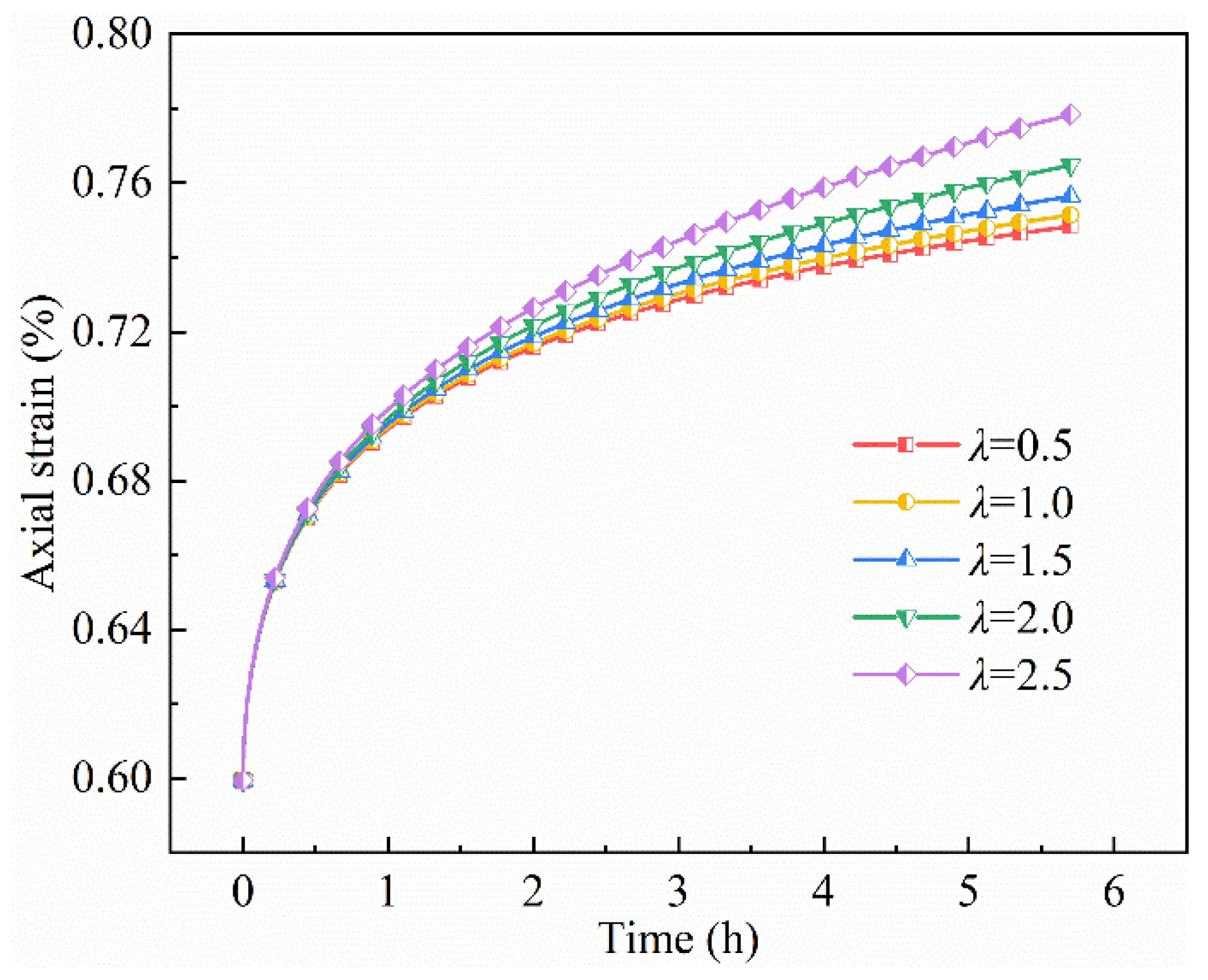
The creep curves corresponding to different values of parameter λ are shown in Figure 21. It can be observed that as λ increases from 0.5 to 2.5, the slope of the curve during the steady-state creep stage gradually increases, indicating a significant increase in the rate of strain accumulation over the same time period. When λ = 0.5, the curve is relatively flat, with strain increasing approximately linearly and slowly with time. However, as λ increases to 2.5, the slope of the steady-state creep stage significantly increases, resulting in an approximately 4% increase in strain within 6 h. Further analysis combining Equations (10) and (16) reveals that an increase in the value of λ accelerates the decay of the viscosity coefficient, thereby weakening the material’s resistance to deformation and significantly promoting the development of creep strain. This mechanism implies that a higher λ value may prompt the material to enter the accelerated creep stage more quickly, potentially even inducing instability and subsequently reducing its creep life.
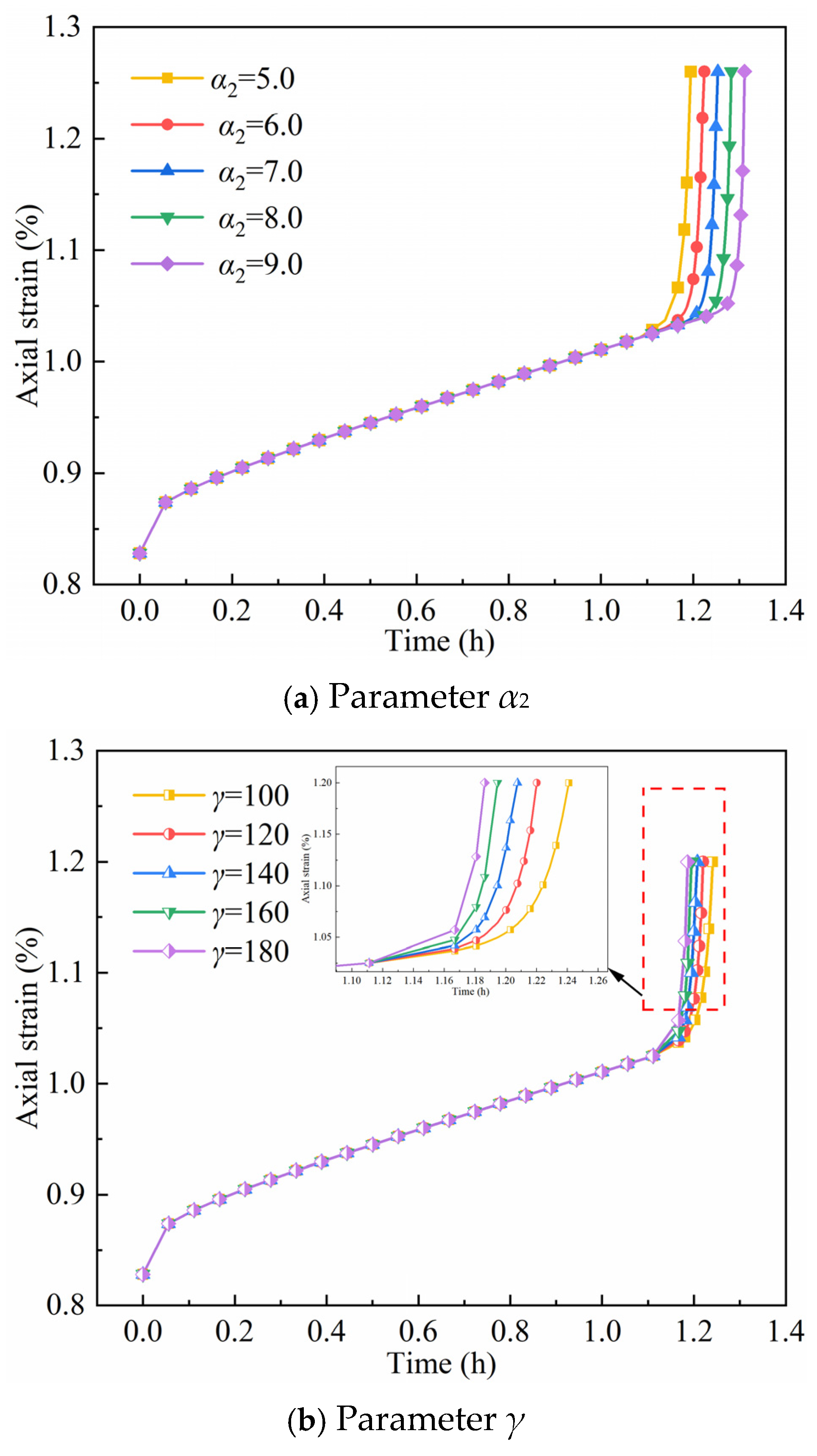
Figure 22 illustrates the influence of varying parameters α2 and γ on the accelerated creep curves. As shown, both parameters have a significant regulatory effect on the creep rate, but their mechanisms of action differ significantly. A comparison between Figure 22a,b reveals that α2 is negatively correlated with the accelerated creep rate, whereas γ has a positive correlation. Analysis based on Equations (12) and (17) indicates that an increase in γ promotes the accumulation of time-dependent damage, leading to a decrease in the viscosity coefficient, resulting in a rapid increase in the creep rate and a forward shift in the inflection point on the accelerated creep curve. Conversely, an increase in α2 accelerates the decay rate of the Mittag-Leffler function, thereby enhancing the long-term strain accumulation effect. As a result, the entry into the accelerated creep stage is delayed, shifting the corresponding inflection point backward.

5. Conclusions

This study investigates the creep behavior of PE fiber-modified HWM through uniaxial compression tests and multi-stage loading creep tests and establishes a fractional-order viscoelastic-plastic damage model to characterize its time-dependent deformation mechanism. The key conclusions drawn from the research are as follows:
(1)
The incorporation of PE fiber significantly improves the long-term mechanical performance of HWM. The uniaxial compressive strength and long-term strength of modified HWM first increase linearly and then decrease with increasing PE fiber content, with an optimal volume fraction of 0.3%. At this optimal content, the long-term strength reaches 9.93 MPa, which is 10.3% higher than that of pure HWM, and the creep failure time is extended by 26.2% compared to the unfilled group. Based on the test results, it is recommended to use HWM reinforced with 0.3% volumetric PE fiber for backfilling roads in deep mines to ensure superior creep stability.
(2)
The creep behavior of PE fiber-modified HWM exhibits significant stress dependence. When the applied stress is lower than the long-term strength, the creep process only undergoes the attenuation creep stage, and the deformation gradually stabilizes with time; when the stress exceeds the long-term strength, the creep curve presents three typical stages: attenuation creep, steady-state creep, and accelerated creep. At the same stress level, the creep strain of modified HWM decreases with the increase in PE fiber content, and the inhibition effect on creep deformation is more pronounced under high-stress conditions.
(3)
A fractional-order viscoelastic-plastic damage model integrating the Riemann–Liouville fractional integral operator and time-dependent damage evolution equation is proposed. The model combines the Hookean body, fractional-order Kelvin model, and improved viscoplastic damage element, which can accurately describe the entire creep process (decaying, steady-state, and accelerated creep) of PE fiber-modified HWM under different stress levels. The fitting results show that the correlation coefficient between the model prediction curve and the experimental data is higher than 0.98, indicating excellent prediction accuracy and reliability. However, to enhance the model’s applicability under conditions that more closely resemble realistic mining environments, the key directions for subsequent research should encompass incorporating three-dimensional stress states and accounting for the effects of the temperature field.
(4)
Parameter sensitivity analysis reveals that the fractional-order parameter α1 is a core parameter regulating the attenuation creep behavior, and its variation in the range of 0.6–0.8 significantly alters the viscoelastic response of the material. The parameter λ controls the steady-state creep rate by affecting the decay of the viscosity coefficient, while α2 and γ jointly regulate the accelerated creep stage: α2 is negatively correlated with the accelerated creep rate and delays the onset of accelerated creep, whereas γ promotes damage accumulation and accelerates creep failure.

Author Contributions

Conceptualization, Y.S. and R.H.; methodology, Y.S. and R.H.; software, Y.Y. and R.X.; validation, P.Z., L.L. and H.W.; formal analysis, L.L. and H.W.; investigation, P.Z. and L.L.; resources, Y.S. and R.H.; data curation, L.L. and H.W.; writing—original draft preparation, Y.S. and R.H.; writing—review and editing, Y.S. and R.H.; visualization, Y.Y. and R.X.; supervision, P.Z.; project administration, Y.S.; funding acquisition, P.Z. Authors equally contributed to this work. All authors have read and agreed to the published version of the manuscript.

Funding

This work is supported by the National Natural Science of China (grant number 52004098) and the Science and Technology Project of Henan Province (grant number 252102240082).

Data Availability Statement

All the data used to support the findings of this study are included within the article.

Conflicts of Interest

The authors declare that they have no competing interests.

References

  1. Yang, G.; Yang, X.J.; He, M.C.; Zhang, J.; Wang, H.S.; Shi, Z.; Yang, F.; Hou, S.L. Experimental and numerical investigations of goaf roof failure and bulking characteristics based on gob-side entry retaining by roof cutting. Eng. Fail. Anal. 2024, 158, 108000. [Google Scholar] [CrossRef] [Scilit]
  2. Wu, B.W.; Wang, X.Y.; Bai, J.B.; Wu, W.D.; Zhu, X.X.; Li, G.D. Study on crack evolution mechanism of roadside backfill body in gobside entry retaining based on UDEC trigon model. Rock Mech. Rock Eng. 2019, 52, 3385–3399. [Google Scholar] [CrossRef] [Scilit]
  3. Bai, J.B.; Shen, W.L.; Guo, G.L.; Wang, X.Y.; Yu, Y. Roof deformation, failure characteristics, and preventive techniques of gob-side entry driving heading adjacent to the advancing working face. Rock Mech. Rock Eng. 2015, 48, 2447–2458. [Google Scholar] [CrossRef] [Scilit]
  4. Yang, J.; He, M.C.; Cao, C. Design principles and key technologies of gob side entry retaining by roof pre-fracturing. Tunn. Undergr. Space Technol. 2019, 90, 309–318. [Google Scholar] [CrossRef] [Scilit]
  5. Zhu, G.L.; Sousa, R.L.; He, M.C.; Zhou, P.; Yang, J. Stability analysis of a non-pillar-mining approach using a combination of discrete fracture network and discrete-element method modeling. Rock Mech. Rock Eng. 2020, 53, 269–289. [Google Scholar] [CrossRef] [Scilit]
  6. Tan, Y.L.; Yu, F.H.; Ning, J.G.; Zhao, T.B. Design and construction of entry retaining wall along a gob side under hard roof stratum. Int. J. Rock Mech. Min. Sci. 2015, 77, 115–121. [Google Scholar] [CrossRef] [Scilit]
  7. Xin, J.L.; Zhang, Z.Z.; Yu, W.J.; Deng, M. Stability analysis of roof-filling body system in gob-side entry retained. Geomech. Eng. 2024, 36, 27–37. [Google Scholar]
  8. Sun, X.M.; Zhao, C.W.; Li, G.; Zhang, B.; Wang, J.W.; Cai, F. Physical model experiment and numerical analysis on innovative gob-side entry retaining with thick and hard roofs. Arab. J. Geosci. 2020, 13, 1245. [Google Scholar] [CrossRef] [Scilit]
  9. Zhang, Z.Z.; Bai, J.B.; Wang, X.Y.; Xu, Y.; Yan, S.; Liu, H.L.; Wu, W.D.; Zhang, W.G. Review and development of surrounding rock control technology for gob-side entry retaining in China. J. China Coal Soc. 2023, 48, 3979–4000. (In Chinese) [Google Scholar]
  10. Li, T.; Cheng, G.B.; Qin, Z.C.; Li, Q.H.; Cao, B.; Liu, Y.L. The gob-side entry retaining with the high-water filling material in Xin’an Coal Mine. Geomech. Eng. 2020, 22, 541–552. [Google Scholar]
  11. Chang, Q.L.; Tang, W.J.; Xu, Y.; Zhou, H.Q. Research on the width of filling body in gob-side entry retaining with high-water materials. Int. J. Min. Sci. Technol. 2018, 28, 519–524. [Google Scholar] [CrossRef] [Scilit]
  12. Xie, S.R.; Wang, E.; Cheng, D.D.; Li, H.; Jiang, Z.S.; Yang, H.Z. Stability analysis and control technology of gob-side entry retaining with double roadways by filling with high-water material in gently inclined coal seam. Int. J. Coal Sci. Technol. 2022, 9, 52. [Google Scholar] [CrossRef] [Scilit]
  13. Zhou, J.L.; Pan, J.F.; Xia, Y.X.; Du, T.T.; Liu, W.G.; Zhang, C.Y. Mechanism and prevention of coal bursts in gob-side roadway floor under thick and hard roof in the deep mining area of Ordos. Int. J. Coal Sci. Technol. 2024, 11, 80. [Google Scholar] [CrossRef] [Scilit]
  14. Zhao, X.Q.; Bai, J.B.; Wen, J.T.; Deng, M.; Zhang, D.; Zhu, Q.C. Impact of non-isostatic curing conditions on the engineering properties of early-age high water-resistant concrete materials. Constr. Build. Mater. 2024, 418, 135265. [Google Scholar] [CrossRef] [Scilit]
  15. Sun, C.D.; Zhang, D.S.; Wang, X.F.; Zhou, R. Large-size test on creep characteristics of high water material for filling body beside roadway. J. Min. Saf. Eng. 2012, 29, 487–491. (In Chinese) [Google Scholar]
  16. Zuo, J.P.; Hong, Z.J.; Xiong, Z.Q.; Wang, C.; Song, H.Q. Influence of different W/C on the performances and hydration progress of dual liquid high water backfilling material. Constr. Build. Mater. 2018, 190, 910–917. [Google Scholar] [CrossRef] [Scilit]
  17. Zhou, X.L.; Liu, C.W.; Liu, Y.; Wang, C.; Ma, Y.J. Effect of dry-wet cycling on the mechanical properties of high-water materials. Adv. Civ. Eng. 2020, 2020, 2605751. [Google Scholar] [CrossRef] [Scilit]
  18. Li, X.F.; Xiong, Z.Q.; Wang, P. Experimental study on improvement of mechanical properties of high-water filling materials in gob-side entry retaining. China Saf. Sci. J. 2020, 30, 95–100. (In Chinese) [Google Scholar]
  19. Li, X.F.; Xiong, Z.Q.; Zhang, Y.H.; Su, C.D. Modification test and engineering application of high-water filling material in gob-side entry retaining. J. Chongqing Univ. 2020, 43, 94–106. (In Chinese) [Google Scholar]
  20. Li, X.L.; Liu, C.W. Creep mechanical properties and creep model of high water material under step loading. J. Appl. Polym. Sci. 2021, 138, e50707. [Google Scholar] [CrossRef] [Scilit]
  21. Zhou, Q.; Liu, J.H. Study on creep property and damage evolution of rich-water packing material for mining. J. China Coal Soc. 2018, 43, 1878–1883. (In Chinese) [Google Scholar]
  22. Xie, H.; Chen, Y. Experimental research on creep laws of high-water material under real pressure water environment. Key Eng. Mater. 2016, 705, 350–354. [Google Scholar] [CrossRef] [Scilit]
  23. Wang, D.; Zeng, J.H.; Liu, C.W.; Xu, Y.H. Creep law and rheological model of high-water rapid-setting material in water environment. J. Sichuan Univ. (Eng. Sci. Ed.) 2014, 46, 1–6. [Google Scholar]
  24. Yan, X.Y.; Wang, F.X.; Luo, Y.H.; Liu, X.H.; Yang, Z.X.; Mao, H.M. Mechanical performance study of basalt-polyethylene fiber reinforced concrete under dynamic compressive loading. Constr. Build. Mater. 2023, 409, 133935. [Google Scholar] [CrossRef] [Scilit]
  25. Xie, H.Z.; Wei, P.; Liu, N.; Gao, J.; Yang, L.Y.; Li, J.H.; Chen, S.Y. Study on failure characteristics of basalt fiber reactive powder concrete under uniaxial loading. Constr. Build. Mater. 2023, 404, 133246. [Google Scholar] [CrossRef] [Scilit]
  26. Wu, S.K.; Zhang, J.W.; Xu, Y.L.; Song, Z.X.; Fan, W.B.; Zhang, Y.; Dong, X.K.; Cheng, Z.S.; Xiao, B.; Zhang, J.T. Research and engineering application on physical and mechanical properties of coal mine high water filling materials. J. Min. Saf. Eng. 2023, 40, 754–763. (In Chinese) [Google Scholar]
  27. Jiao, H.Z.; Chen, X.; Yang, Y.X.; Chen, X.M.; Yang, L.H.; Yang, T.Y. Mechanical properties and meso-structure of concrete under the interaction between basalt fiber and polymer. Constr. Build. Mater. 2023, 404, 133223. [Google Scholar] [CrossRef] [Scilit]
  28. Liu, A.; Kong, D.W.; Jiang, J.T.; Wang, L.L.; Liu, C.; He, R.Y. Mechanical properties and microscopic mechanism of basalt fiber-reinforced red mud concrete. Constr. Build. Mater. 2024, 416, 135155. [Google Scholar] [CrossRef] [Scilit]
  29. Hoang, T.V.; Widjaja, J.; Qiang, L.Y.; Liu, M.K.; Alexander, T.J.; Runge, A.F.J.; Sterke, C.M.D. Nonlinear wave propagation governed by a fractional derivative. Nat. Commun. 2025, 16, 5469. [Google Scholar] [CrossRef] [Scilit] [PubMed]
  30. Bouras, Y.; Vrcelj, Z. Fractional and fractal derivative-based creep models for concrete under constant and time-varying loading. Constr. Build. Mater. 2023, 367, 130324. [Google Scholar] [CrossRef] [Scilit]
  31. Bouras, Y.; Zorica, D.; Atanacković, M.T.; Vrcelj, Z. A non-linear thermo-viscoelastic rheological model based on fractional derivatives for high temperature creep in concrete. Appl. Math. Model. 2018, 55, 55551–55568. [Google Scholar] [CrossRef] [Scilit]
  32. Praveenkumar, B.; Veeresha, P. Chaos and control in a fractional-order financial model: A non-local dynamical approach. Int. J. Dyn. Control 2025, 13, 360. [Google Scholar] [CrossRef] [Scilit]
  33. Wang, R.; Zhuo, Z.; Zhou, H.W.; Liu, J.F. A fractal derivative constitutive model for three stages in granite creep. Results Phys. 2017, 7, 2632–2638. [Google Scholar] [CrossRef] [Scilit]
  34. Cao, P.; Wen, Y.D.; Wang, Y.X.; Yuan, H.P.; Yuan, B.X. Study on nonlinear damage creep constitutive model for high-stress soft rock. Environ. Earth Sci. 2016, 75, 900. [Google Scholar] [CrossRef] [Scilit]
  35. Yang, S.Q.; Cheng, L. Non-stationary and nonlinear visco-elastic shear creep model for shale. Int. J. Rock Mech. Min. Sci. 2011, 48, 1011–1020. [Google Scholar] [CrossRef] [Scilit]
  36. Hou, R.B.; Zhang, K.; Tao, J.; Xue, X.R.; Chen, Y.L. A nonlinear creep damage coupled model for rock considering the effect of initial damage. Rock Mech. Rock Eng. 2019, 52, 1275–1285. [Google Scholar] [CrossRef] [Scilit]
  37. Hou, R.; Cui, Q.; Guo, Y.; Shi, Y.; Fu, J. A new elasto-visco-plastic damage model and numerical simulation method used for time-dependent behavior prediction of deep tunnel. Comput. Geotech. 2024, 168, 106129. [Google Scholar] [CrossRef] [Scilit]
  38. Kabwe, E.; Karakus, M.; Chanda, K.E. Isotropic damage constitutive model for time-dependent behaviour of tunnels in squeezing ground. Comput. Geotech. 2020, 127, 103738. [Google Scholar] [CrossRef] [Scilit]
  39. Wang, J.B.; Zhang, Q.; Song, Z.P.; Feng, S.J.; Zhang, Y.W. Nonlinear creep model of salt rock used for displacement prediction of salt cavern gas storage. J. Energy Storage 2022, 48, 103951. [Google Scholar] [CrossRef] [Scilit]
  40. Krajcinovic, D. Damage mechanics. Mech. Mater. 1989, 8, 117–197. [Google Scholar] [CrossRef] [Scilit]
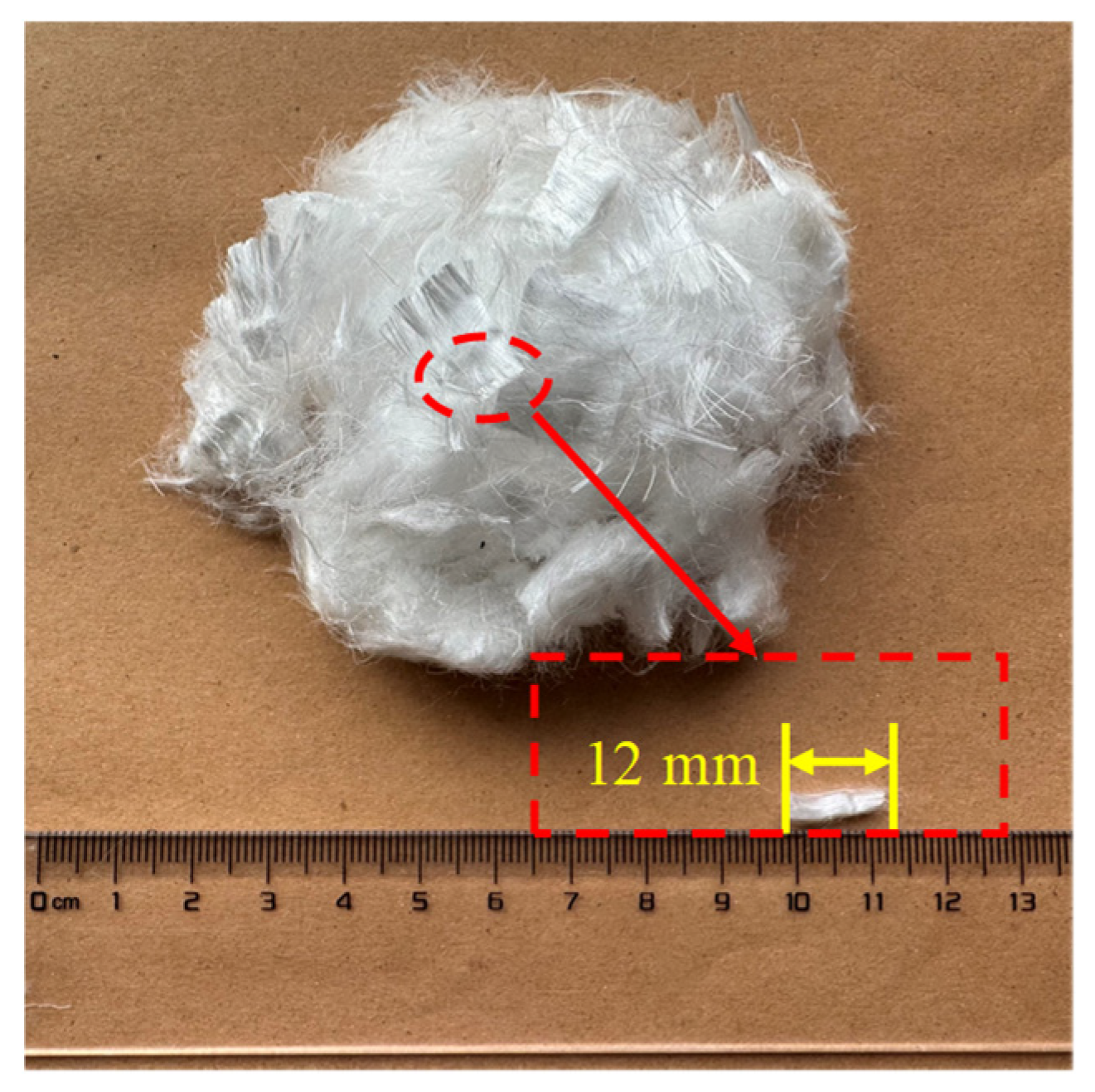
Figure 1. Macroscopic morphology of PE fibers.
Fractalfract 10 00095 g001
Figure 2. Specimen preparation process for PE fiber-modified HWM.
Fractalfract 10 00095 g002
Figure 3. Average compressive strength of PE fiber-modified HWM.
Fractalfract 10 00095 g003
Figure 4. Experiment equipment.
Fractalfract 10 00095 g004
Figure 5. Strain-time curve of modified HWM with different PE fiber content.
Fractalfract 10 00095 g005
Figure 6. Creep curves of modified HWM with different PE fiber content.
Fractalfract 10 00095 g006
Figure 7. Relationship curve between creep strain and creep stress level of PE fiber-modified HWM specimens.
Fractalfract 10 00095 g007
Figure 8. Isochronous stress–strain curve of HWM with different PE fiber content.
Fractalfract 10 00095 g008aFractalfract 10 00095 g008b
Figure 9. Relationship between the long-term strength of modified HWM and the content of PE fiber.
Fractalfract 10 00095 g009
Figure 10. Relationship between the creep failure time of modified HWM and the content of PE fiber.
Fractalfract 10 00095 g010
Figure 11. Failure modes of the pure HWM specimen and the PE fiber-reinforced HWM specimen.
Fractalfract 10 00095 g011
Figure 12. Abel dashpot.
Fractalfract 10 00095 g012
Figure 13. Creep curve at different values of α.
Fractalfract 10 00095 g013
Figure 14. Fractional viscoelastic model.
Fractalfract 10 00095 g014
Figure 15. Fractional viscoplastic damage model.
Fractalfract 10 00095 g015
Figure 16. Schematic diagram of the creep curve for PE fiber-modified HWM under different stress levels.
Fractalfract 10 00095 g016
Figure 17. Fractional-order viscoelastic-plastic damage model of PE fiber-modified HWM.
Fractalfract 10 00095 g017
Figure 18. Comparison of creep test data and model fitting results for HWM specimens with different PE volume fractions.
Fractalfract 10 00095 g018
Figure 19. Comparison of the proposed creep model with the classical creep model.
Fractalfract 10 00095 g019
Figure 20. Effect of parameter α1 on the creep curve.
Fractalfract 10 00095 g020
Figure 21. Effect of parameter λ on the creep curve.
Fractalfract 10 00095 g021
Figure 22. Effect of parameters α2 and γ on the accelerated creep curve.
Fractalfract 10 00095 g022
Table 1. Chemical composition of HWM (%).
Raw MaterialCaOAl2O3SiO2Fe2O3SO3MgO
CAS43.3732.168.733.617.231.213.69
Gypsum37.840.923.120.3245.253.588.97
Lime71.220.852.430.870.541.9822.11
Table 2. Physical and mechanical properties of PE fiber.
Density
(g/cm3)
Diameter
(μm)
Length
(mm)
Tensile Strength
(GPa)
Elastic Modulus
(GPa)
Fracture Elongation
(%)
0.9716123.81403.5
Table 3. Uniaxial compressive strength of the PE-reinforced HWM.
Volume Fraction of PE Fiber (%)Specimen IDCompressive Strength (MPa)Average Compressive Strength (MPa)Standard Deviation (MPa)
0PE0-19.8410.310.36
PE0-210.70
PE0-310.39
0.1BF0.1-111.0811.050.18
BF0.1-211.15
BF0.1-310.92
0.2BF0.2-112.0912.100.27
BF0.2-211.77
BF0.2-312.44
0.3BF0.3-112.5112.830.30
BF0.3-212.75
BF0.3-313.23
0.4BF0.4-110.7110.710.14
BF0.4-210.87
BF0.4-310.54
Table 4. Creep stress levels of HWM specimens.
Creep Stress (MPa)
1st2nd3rd4th5th6th7th
6789101112
Table 5. Creep parameters of HWM specimens with different PE fiber volume fractions.
Fiber ContentStress
(MPa)
E1
(GPa)
E2
(GPa)
η1
(GPa·h)
α1η2
(GPa·h)
η3
(GPa·h)
α2λγ
0%61.7412.9523.070.67
71.547.6712.130.60
81.3711.1627.330.45
91.3211.0816.170.59
101.254.153.580.6413.96 0.05
0.1%61.8710.0216.390.51
71.655.2315.720.45
81.562.1713.550.37
91.471.7810.100.34
101.345.564.280.5513.96 0.54
0.2%62.0215.8926.710.74
71.817.8618.940.62
81.665.4312.170.53
91.552.6512.230.44
101.443.859.260.4713.96 0.22
111.355.377.540.5213.96 0.14
0.3%62.2011.7520.940.61
71.937.8318.470.51
81.854.3314.570.41
91.754.8010.010.47
101.664.977.420.5413.96 0.94
111.586.586.810.5813.96 0.09
121.4413.188.010.3313.964.925.692.10133.97
Table 6. Creep parameters of HWM specimens with 0.3% PE fiber volume fractions.
Stress
(MPa)
E1
(GPa)
E2
(GPa)
η1
(GPa·h)
α1η2
(GPa·h)
η3
(GPa·h)
α2λγ
62.2011.7520.940.61
101.664.977.420.5413.96 0.93
121.4413.188.010.3313.964.925.692.10133.97
Disclaimer/Publisher’s Note: The statements, opinions and data contained in all publications are solely those of the individual author(s) and contributor(s) and not of MDPI and/or the editor(s). MDPI and/or the editor(s) disclaim responsibility for any injury to people or property resulting from any ideas, methods, instructions or products referred to in the content.