1. Introduction
Haptic displays have been extensively explored in assistive technology solutions for individuals with visual impairments. Tactile vision sensory substitution devices use haptic displays to present visual images to the sense of touch. This ‘haptic display’ area of research can be divided into two possible approaches: (1) conversion of information about pictures to touch, or (2) conversion of complete pictures to touch. In the first approach, an image is first processed by a computer to determine information about the image, such as distance to the nearest object, then vibration or other tactile signals are used to convey this information to the user [
1]. Haptic face recognition [
2,
3,
4] and the human-computer interface system that is studied by D. Hong et al. [
5] are examples of this approach.
The second approach has the significant benefit of potentially giving the user an effective replacement for vision. This area of research relies upon an assumption that the brain is capable of a type of plasticity known as ‘sensory substitution’, in which information provided via one sense can be interpreted by the brain as information from a different sense [
6,
7,
8]. In the second approach, there are two main types of haptic display devices. The first type of display is the electrotactile display, commonly placed on the tongue. The second main type of display is the vibration display. Brainport is the popular example of using the electro tactile displays, a device which consists of a video camera mounted on a sunglass and an electrode array [
9,
10,
11]. The image captured by the camera is converted to a black and white image in software, and pixels from the camera are felt on the tongue via an electrode array [
12]. Besides the electro-tactile display, the vibration displays use vibration motors. While the electrode approach is typically limited to placement on the tongue due to its wetness and, thus, high conductivity, vibration motor devices can be placed on any area of skin. This approach commonly uses vibration motors, camera, and a processing unit [
13,
14]. The image captured by the camera is processed into a vibration level for an array of vibration motors corresponding to the image.
However, all of the haptic display solutions found in the literature have two primary complications: The low resolution and the one-pin-per-element problem. Resolution is the number of pixels contained in an image. A visual digital image commonly has a resolution such as 640 × 480 or 720 × 1080 pixels, but the current highest- resolution tactile display has much lower resolution such as less than 20 × 20. Since a visual image becomes more difficult to interpret, the lower the resolution is, it is expected that the low resolution such as 20 × 20 would not be enough to deliver an image to a viewer. Another problem, the one pin per element problem, stems from the need to individually control each tactile pixel independently of all the others. In order to accomplish this individual control, a single pin of a microcontroller is needed for each tactile element. Thus, in order to achieve a resolution of even 20 × 20, 400 individual pins would be required, as well as 400 individual pulse-width modulation signals and their corresponding clocks.
To solve these problems and achieve high resolution, we have proposed the resonant microbeam vibrotactile haptic display [
15,
16]. In this paper, the concept of the resonant microbeam vibrotactile haptic display is briefly reviewed. The following human touch experiments are presented: dried skin contact, wet and soaped skin contact, skin contact to a constraint and metal beam tips, maximum normal force measurement, and skin contact to silicon rubber beams attached to the metal beam tips. The forced response of a metal beam depending on the silicone rubber beam length is also presented.
2. The Concept of the Resonant Microbeam Vibrotactile Haptic Display
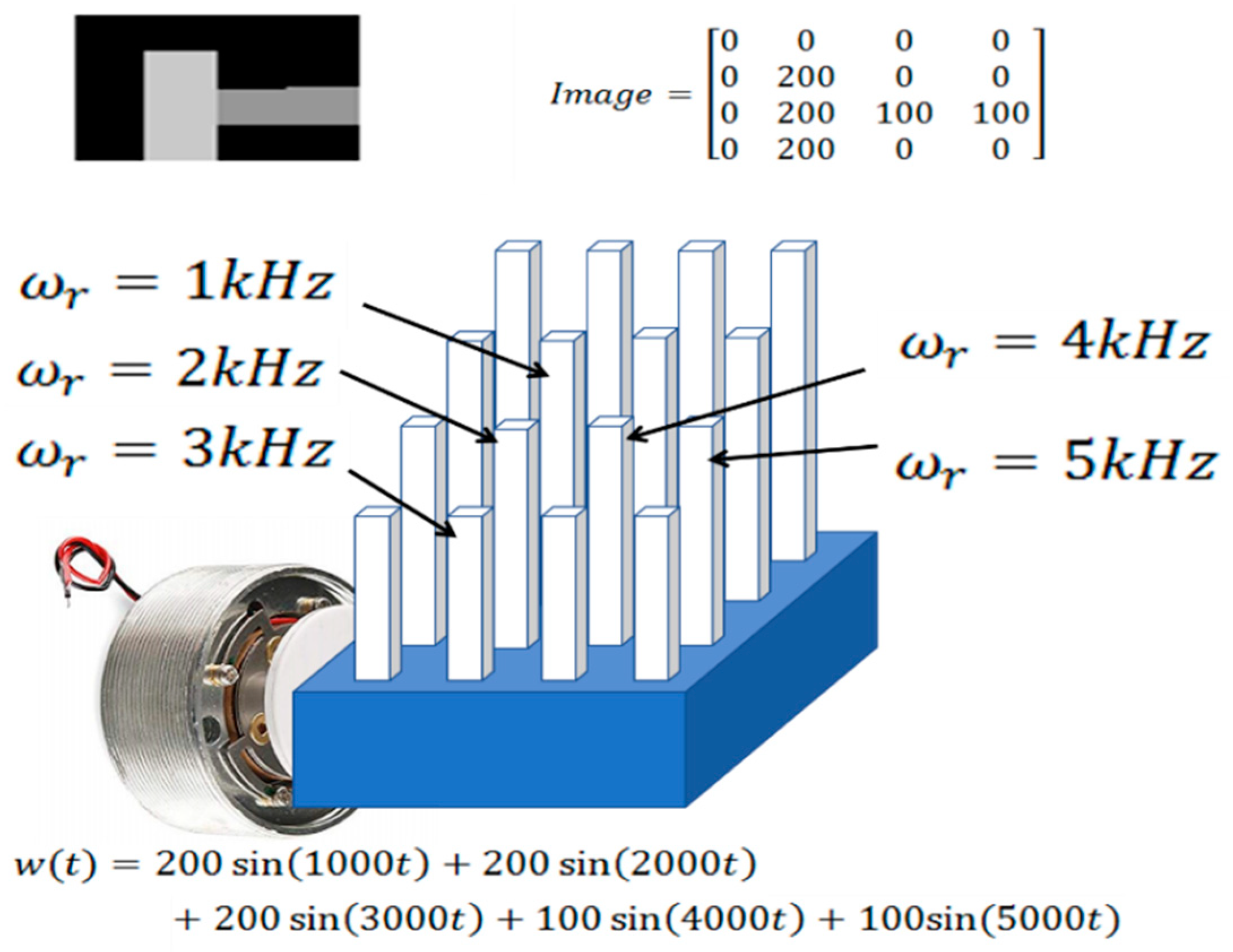
A resonant microbeam vibrotactile array is a mechatronic system that consists of two subsystems: a beam array and a beam array controller. The beam array consists of cantilever beams made of a metal material, which has low damping ratio to reduce the crosstalk between each beam vibration. Each beam in the array is designed to have a unique length and/or cross-sectional area, so that each beam can be controlled individually by having a unique natural frequency. The base of the beam array is attached to a surface transducer or a speaker that is actuated to vibrate, as shown in
Figure 1.
A surface transducer is a device that turns almost any surface into a speaker. In a surface transducer, there is no cone, and a coil is attached to a metal pad so that the vibration transmits the pad into any subject it is attached to. In the proposed device, the forcing vibration from a surface transducer excites the beam base. This approach uses the concept of ‘resonance’. When the frequency of the vibration of the surface transducer matches the natural frequency of one of the beams, that beam ‘resonates’—vibrates with large amplitude. Since the natural frequency of each beam is unique, each beam can represent a different pixel of an image.
For this approach, there are three important criteria: (1) minimizing natural frequency (2) maximizing vibrational amplitude (3) using material having low damping ratio. Considering that the general frequency area for people to feel static touch is less than 500 Hz [
17], it is generally assumed that lower frequencies are more perceivable than higher frequencies even though the perceivable frequency range with dynamic touch is currently unknown. To improve human perception, maximizing vibrational amplitude is important. Since the natural frequency of a beam is inversely proportional to the amplitude of the beam in a lumped mass model of a beam, low frequency is required to maximize human perception [
15]. Therefore, the 1st vibration mode of a metal beam is used in this approach to minimize the natural frequency and maximize the amplitude of a beam. Using material having low damping ratio can reduce the bandwidth of beam vibration, which can make it theoretically possible to make more beams in a given frequency range. To achieve the high resolution of the proposed approach, as many beams as possible will be needed without the crosstalk of vibration between each beam. In our previous research [
15,
16], a beam design simulation algorithm was developed with the consideration of some important criteria mentioned above. It was found that nearly 13,000 beams (96 × 128 resolution) can be made in a single display manufactured by the wire Electric Discharge Machining (EDM) method.
Before moving forward for further development of this device, an important problem was found that beam vibration stops when skin contacts beam tips to perceive beam vibration and no beam vibration is perceived. This paper investigates the methods to reduce the friction occurred at the beam tips where skin directly contacts to solve the user perception problem. Diverse skin contact experiments with resonant tactile microbeams were conducted to identify cases where the metal beams do not cease to vibrate.
3. Finger Contact Experiment
3.1. Dried Finger Contact Experiment
3.1.1. The Setup for Dry Skin Contact Experiment
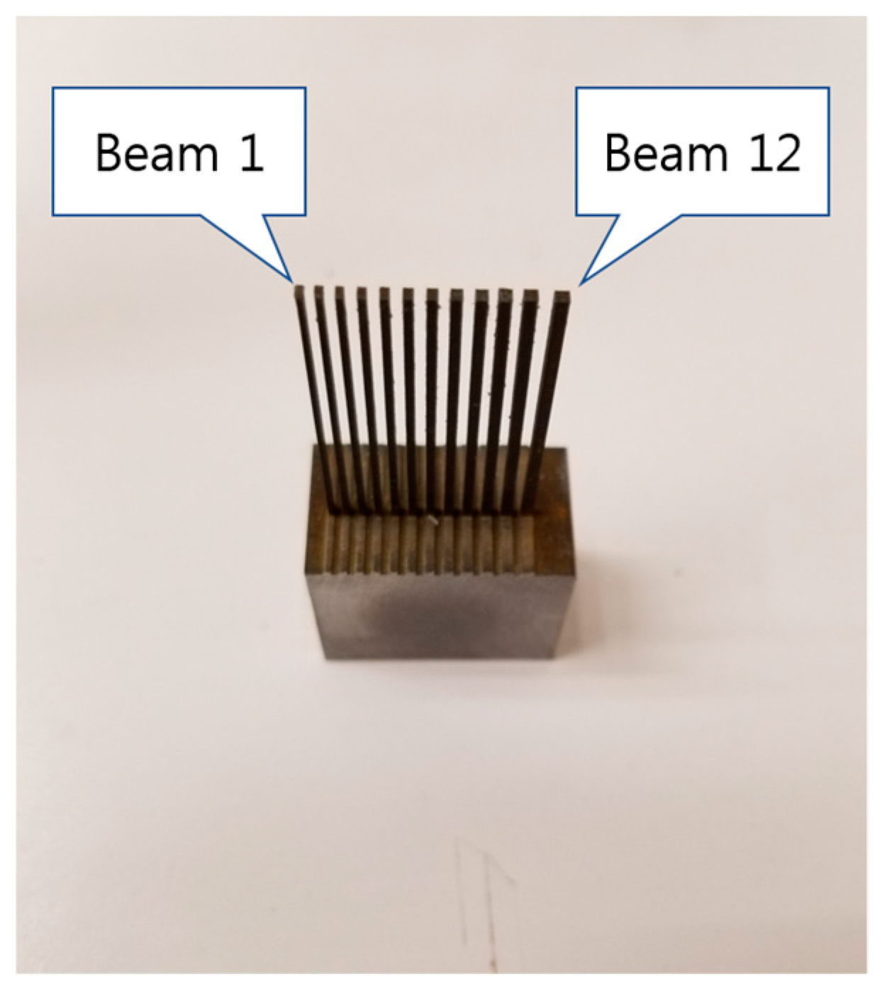
In order for the proposed device to be usable for image perception, individual beam vibration must be perceivable by a user contacting the beams with the skin. The first requirement for perceivability is that the beams must continue to vibrate, while in contact with the skin. To investigate human perceivability and determine whether beams continue to vibrate under skin contact, human skin contact experiments are conducted on a small prototype device. For this experiment, a beam array prototype having a total of 12 cantilever metal beams is selected, as shown in
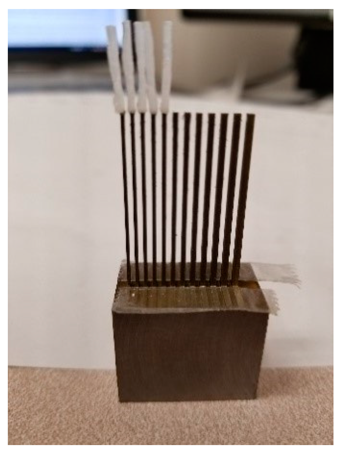
Figure 2. The beam array is designed to have less than 1200 Hz as the resonant frequency range for all metal beams. Every beam has the same length, 29.6 mm, so that the skin of a finger can easily contact all beam tips simultaneously. The beam array is manufactured by wire EDM at Arizona State University. Beam number 1 represents the leftmost beam, and beam number 12 represents the rightmost beam.
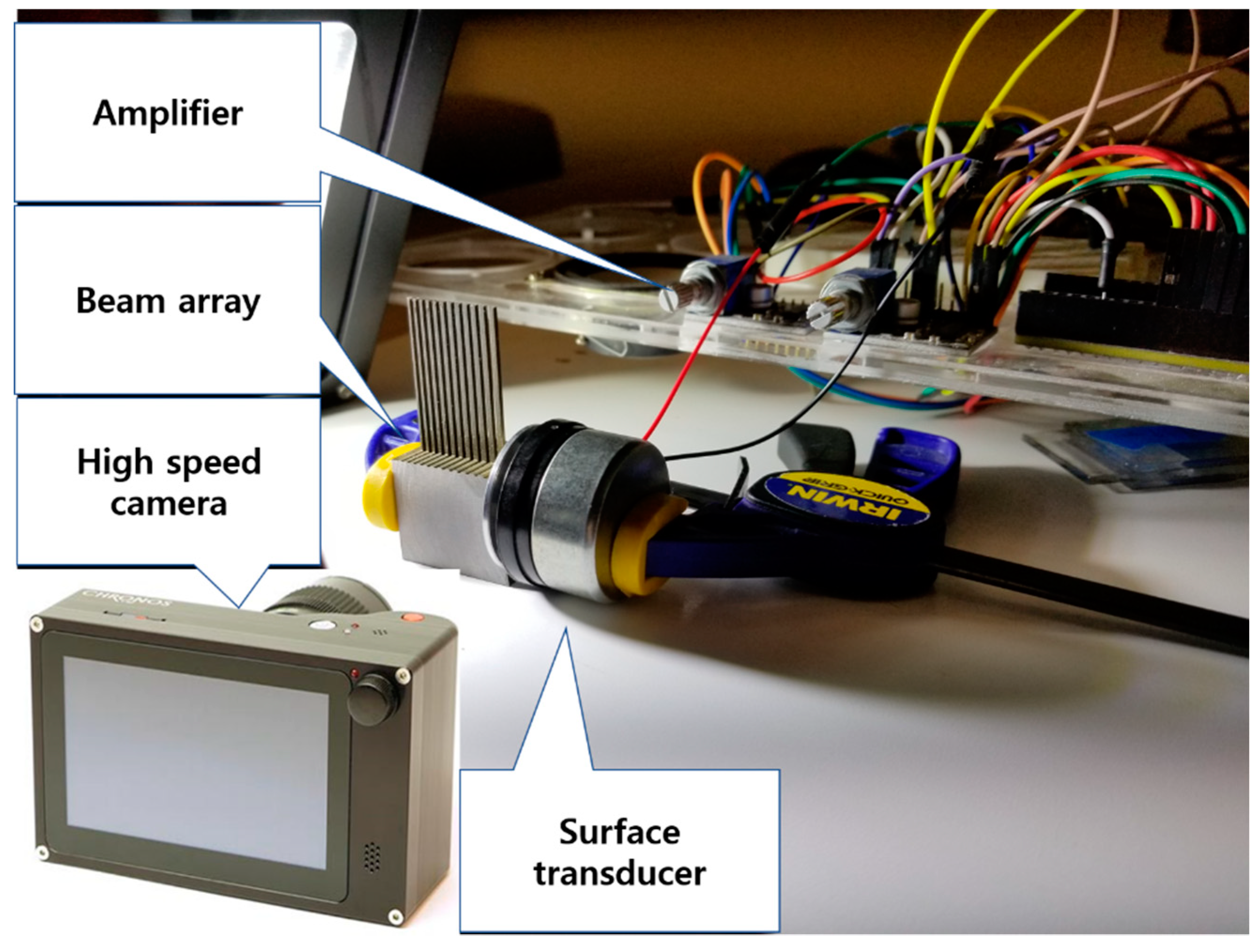
The input of the surface transducer is connected to the output of an amplifier by USB cable, which receives its input from a function generator. The amplifier is provided with a constant 5 V power source. The function generator is set to generate a sine wave of a specified ‘starting frequency’, which is determined by approximating the natural frequency of the beam from a lumped-mass model based on the actual beam dimensions. The amplitude dial of the amplifier is adjusted to a small enough amount that the 1st beam does not hit the 2nd beam when the 1st beam resonates. A high-speed camera is positioned so that the field of view is parallel to the axis of the metal beams to record the beam vibration at the moment a finger touches the beam tips. The high-speed camera is fit with a microscope lens and positioned so that two or three beams are focused in the high-speed camera view simultaneously. A frame rate of 8819 frames per second is used for video recording to capture changes in beam vibrations when a finger touches the metal beams.
Figure 3 shows the experimental setup with a high-speed camera. First, a dried finger presses the beam tips with various forces to see if there is a moment when the beam does not stop.
3.1.2. The Result of Dry Skin Contact Experiment
The recorded video files are checked with eye, and it is found that when the finger touches the beam tip, the amplitude of the vibrating beam decreases, and the beam stops vibrating. After the skin contacts the beam tips, the beam stops vibrating within about 6–10 milliseconds. No beam vibration is perceived under dry skin contact conditions.
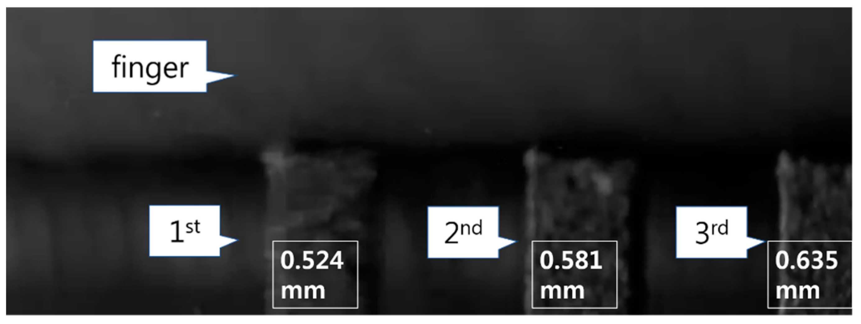
Figure 4 illustrates the moment when a finger touches the beam tips. The three rectangular parts vibrating are the first three thinnest metal beams, and a white object above the three beams is the finger.
The reason for the beam vibration stopping may be the friction that occurs at the contact surface of beam tips and the skin. Here, the friction is the only force introduced by the presence of the skin that is in the direction of the beam vibration (perpendicular to the beam axis), provided that the skin does not protrude below the surface of the beam tips. If the skin does protrude below the surface of the beam tips, then that skin would exert a normal force in the direction perpendicular to the beam axis. However, from the video captured in this experiment, it is shown that the skin actually does not protrude down. This means that the friction is the only force that could stop the beam vibration. The two ways to reduce friction are to reduce the coefficient of friction or to reduce the normal force between the skin and the tops of the metal beams.
3.2. Wet and Soaped Finger Contact Experiment
In the previous experiment with dry skin, it is revealed that the friction generated at the contact of beam tips and the skin is the probable reason for the beam vibration damping when the finger touches it. In this experiment, water and soap are used to reduce the coefficient of the friction.
3.2.1. The Setup for Wet and Soaped Finger Contact Experiment
A previous study by O’Meara and Smith [
18] reveals that the simple presence of soap and water is sufficient to dramatically decrease the coefficient of friction between skin and steel. The same setup, as shown in
Figure 3, is used for wet and soaped finger touch experiment. First, a soaped finger touches the beam tips in a vibrating state, and the vibration response is recorded by a high-speed camera. Then, a wet and soaped finger touches the beam tips, and it is also recorded by the high-speed camera.
3.2.2. The result of Wet and Soaped Finger Contact Experiment
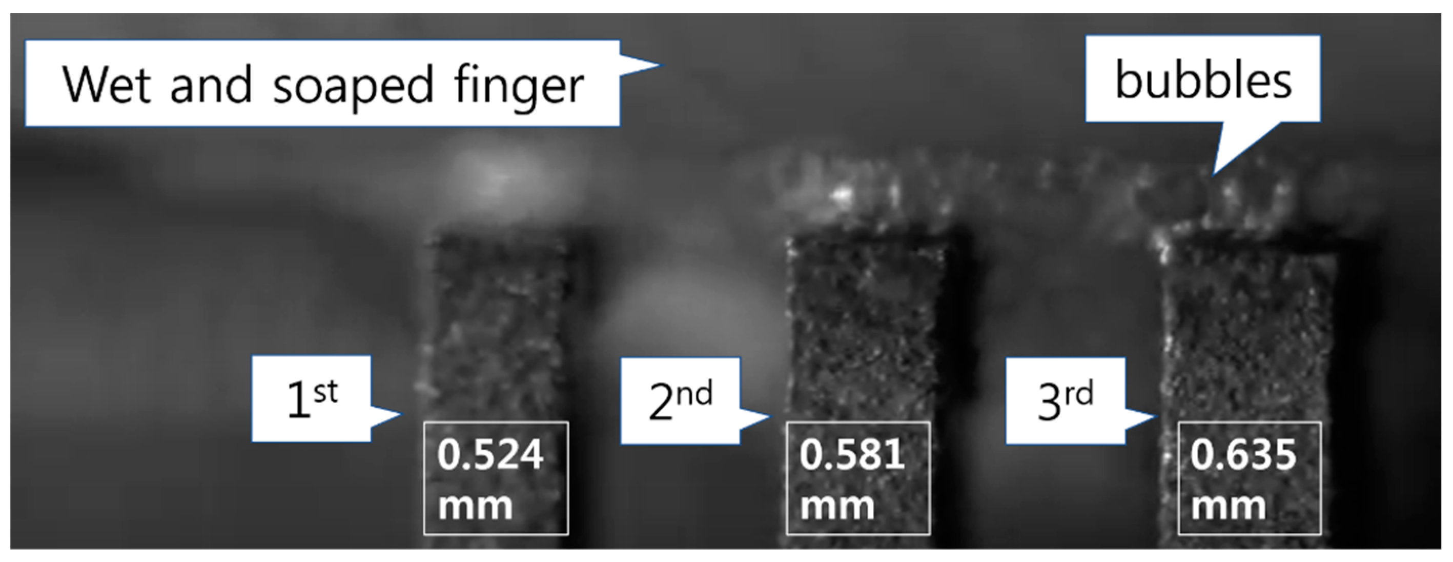
In the observation of the recorded files with eye, it is still found that when the finger that is wet or wet and soaped touches the beam tip, the amplitude of the vibrating beam decreases, and the beam stops vibrating. After the skin contacts the beam tips, the beam stops vibrating within about 6–10 milliseconds.
Figure 5 illustrates the moment when a wet and soaped finger touches beam tips. The three rectangular part is the first three thinnest metal beams, and a white object with bubbles above the three beams is the wet and soaped finger.
3.3. Finger Contact Experiment with Constraints
In this experiment, two constraints of acrylic panels, which have almost the same height as the metal beam tips, are manufactured by a laser cutter to reduce the normal force contributing to the friction. One of the U-shaped acrylic constraints has a height of 29.6 mm, and the other has a height of 29.7 mm, as shown in
Figure 6.
3.3.1. The Setup for Finger Contact Experiment with Constraints Setup
The metal beams of a beam array are located in the channel of the U-shaped acrylic constraint, as shown in
Figure 7. The same high-speed camera setup, as shown in
Figure 3, is used. Since the metal beams do not vibrate when the U-shaped constraint contacts them, a clearance is maintained by using double-sided tape to fix the constraint to the beam base, so that the constraint does not touch the beams.
3.3.2. The Result of Finger Contact Experiment with Constraints
The beam vibration is perceived by tapping the tip of the metal beams, but it is hard to perceive any distinct beam vibration by just touching the beam tips. Beam vibration is perceived, while the beam still vibrates through the finger pressing (touching) the beam very weakly. Even though beam vibration is perceived by touching the beam tip and constraints very weakly, this may not be suitable for use of the device, since it is impossible to maintain the very weak touch with the beams. Another problem is that there is always some vibration transmitted through the U-shaped constraint, and it interferes with recognizing the beam vibration. Moreover, no beam vibration is perceived after the 4th beam, which the resonant frequency is 612 Hz, even though the finger either presses the beam tip very weakly or taps the tip. There might be two possible reasons for the lack of user perception. One is that the amplitude of the 4th beam may be not enough for the user to perceive the vibration. Another reason is that the perceivable frequency range with dynamic touch may be similar to the one with static touch, which is known up to around 500 Hz. To figure out the exact reason, further research will be needed.
3.4. Finger Force Measurement
It is found that with very weak finger touch to the metal beam tips and constraints, the beam vibration can be perceived. In this experiment, the goal is to measure the maximum normal force that does not stop beam vibration.
3.4.1. The Setup for Finger Force Measurement
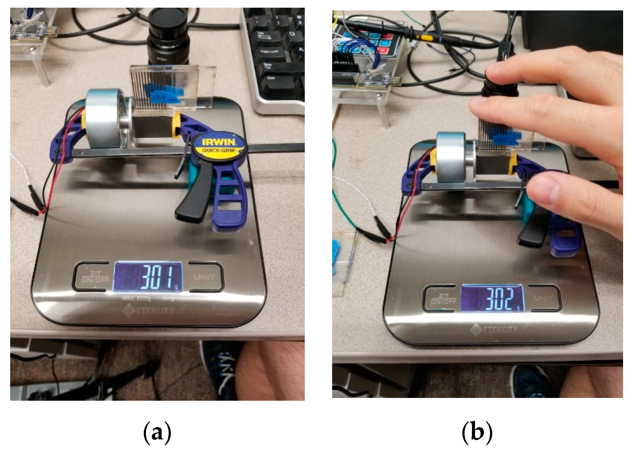
A scale is used to measure the finger force. First, the surface transducer and the beam array with the Acrylic constraint are placed on the scale to measure their weight without a finger press. Then, the vibrating beam tip and constraint are pressed by a finger while the targeted beam vibrates, and the weight caused by the finger force including the whole weight of experimental device is measured, as shown in
Figure 7.
3.4.2. The Result of Finger Force Measurement
In the experiment, it is found that the weight caused by the maximum finger force, which does not stop beam vibration, is less than 1 gram. 1 gram is equal to 0.001 kg, which is 0.001 × 9.81 = 0.01 N. This force is too small force to be maintained continuously when people touch the beam tips. It is found that other methods should be considered to aid the user perception based on this experiment result.
3.5. Finger Touch Experiment with Silicone Rubber Beams
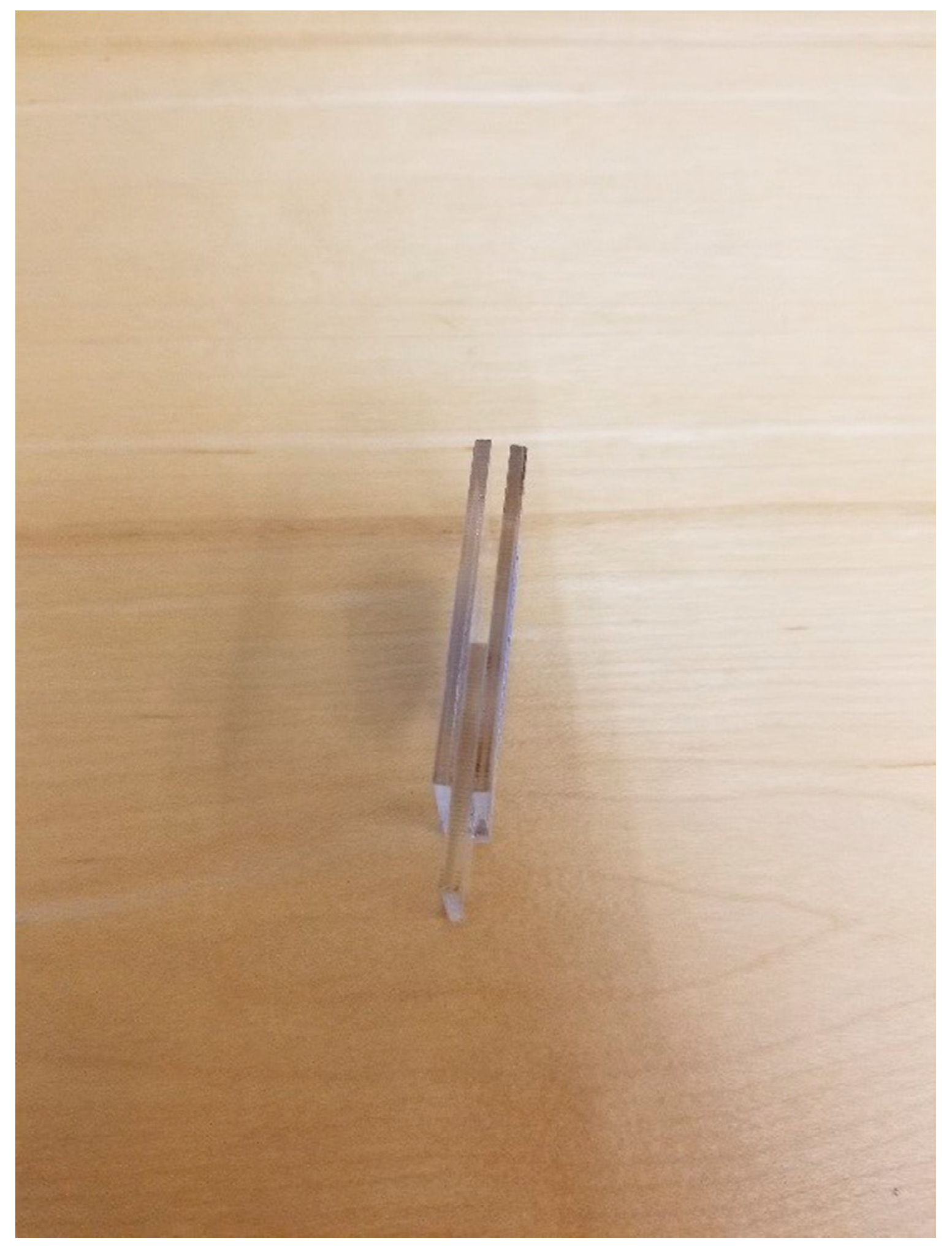
It is found that a new method is needed to reduce the normal force generating from the direct finger touch to the beam tips. For this, a material known as ‘dragon skin 10 very fast’, a type of silicone rubber, is selected to make a silicone rubber beam, which is attached to a metal beam tip so that a finger could only touch the tips of silicone rubber beams and the normal force of the finger would not be exerted on the metal beam tips directly.
3.5.1. The Setup for Finger Touch Experiment with Silicone Rubber Beams
A and B of ‘Dragon Skin 10 very fast’ are mixed and solidified. The solidified dragon skin is cut to make rectangular shaped silicone rubber beams. Two silicone rubber beams are attached to the tips of two beams of the metal prototype with an ethyl cyanoacrylate adhesive. The length of silicone rubber beams is 11.7 mm, and their thicknesses, around 1.1mm, are slightly thicker than the thickness of a metal beam. Since the silicone rubber beams are cut manually, their thickness is not uniform, as shown in
Figure 8. The same experimental setup as shown in
Figure 3 is used to resonate the metal beams to which silicone rubber beams are attached, and a finger touches the silicone rubber beam tip when the beam vibrates in order to perceive the beam vibration. Only two metal beams with silicone rubber beams attached are resonated. After investigating the 2nd metal beam vibration with the long silicone rubber beams, the long silicone rubber beams are cut into the half to investigate the difference of the 2nd beam vibration.
3.5.2. The Result of Finger Touch Experiment with Silicone Rubber Beams
The 2nd metal beam vibration can be perceived by skin contact to the silicone rubber beam attached to the 2nd metal beam after cutting the long silicone rubber beam into the half. However, when the vibration test is conducted, no beam vibration is observed at around their original resonant frequencies, which were used in the previous skin contact experiments. After the silicone rubber beam attached to the 2nd metal beam (the metal beam being observed) is removed from the beam, the distinct beam vibration is observed at around the resonant frequency. This shows that the long silicone rubber beams absorb the beam vibration, and the amplitude of the beam with the long silicone rubber beams becomes smaller. It is also found that the resonant frequency of the metal beams can shift by attaching the silicone rubber beams to the beam tips.
Even though the mechanical properties like damping ratio between the silicone rubber beam and metal beam are different, since the total length of the beams increases due to adding the silicone rubber beams to the top of metal beams; the resonant frequency range of the metal beams are shifted. For example, the frequency of the 1st metal beam is 511 Hz, and it is shifted to 490 Hz after attaching the silicone rubber beams to the tip of the metal beams. In the same way, the resonant frequency of the 2nd metal beam shifted from 569 to 525 Hz, the 3rd shifted from 612 to 580 Hz, and the 4th shifted from 664 to 620 Hz.
Unfortunately, the bandwidth becomes broader after attaching silicone rubber beams. It is found that cutting the silicon rubber with some increments can affect the frequency shift and the bandwidth of the beam vibration.
4. Vibration Response Depending on the Decrease of Silicone Rubber Beam Length
To better understand the effect of the silicone rubber beams on the metal beam bandwidth and amplitude, further experiments are conducted. In this experiment, a total of 46 cases with the silicone rubber beam length changes are investigated, and 434 iterations of a high-speed camera experiment are recorded in order to find the relationship between the dimensions of the silicon rubber beams and the vibrational response of the metal beams.
4.1. The Setup for Vibration Response Depending on the Decrease Of Silicone Rubber Beam Length
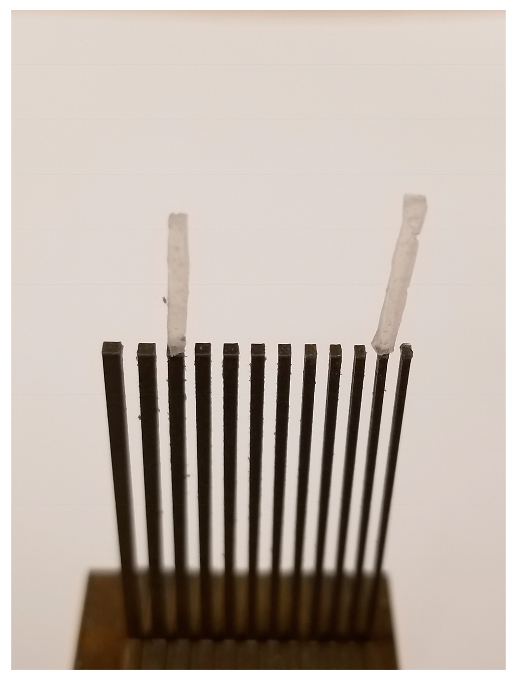
Silicone rubber beams manually cut are attached to the first five thinnest metal beams because these metal beams have larger vibrational amplitudes than the other metal beams. Only the 2nd metal beam is resonated, and its vibration response is recorded. Since the resonant frequency of the 2nd metal beam is different, depending on the length of the silicone rubber beams, the resonant frequency of the beam must be found with eye observation after cutting the silicon rubber beams with an approximate 1mm increment. Then, about ten frequencies including the resonant frequency of the metal beam alone are recorded with the high-speed camera to find the resonant frequency of the metal beam with the silicone rubber beam attached.
Figure 9 shows the silicone rubber beams attached to the first five thinnest metal beams.
4.2. The Result of Vibration Response Depending on the Decrease of Silicone Rubber Beam Length
The recorded vibration response of the 2nd metal beam is analyzed by an optical flow algorithm implemented in Python. The vibration response of the 2nd beam is analyzed depending on the length change of the silicone rubber beams. For example,
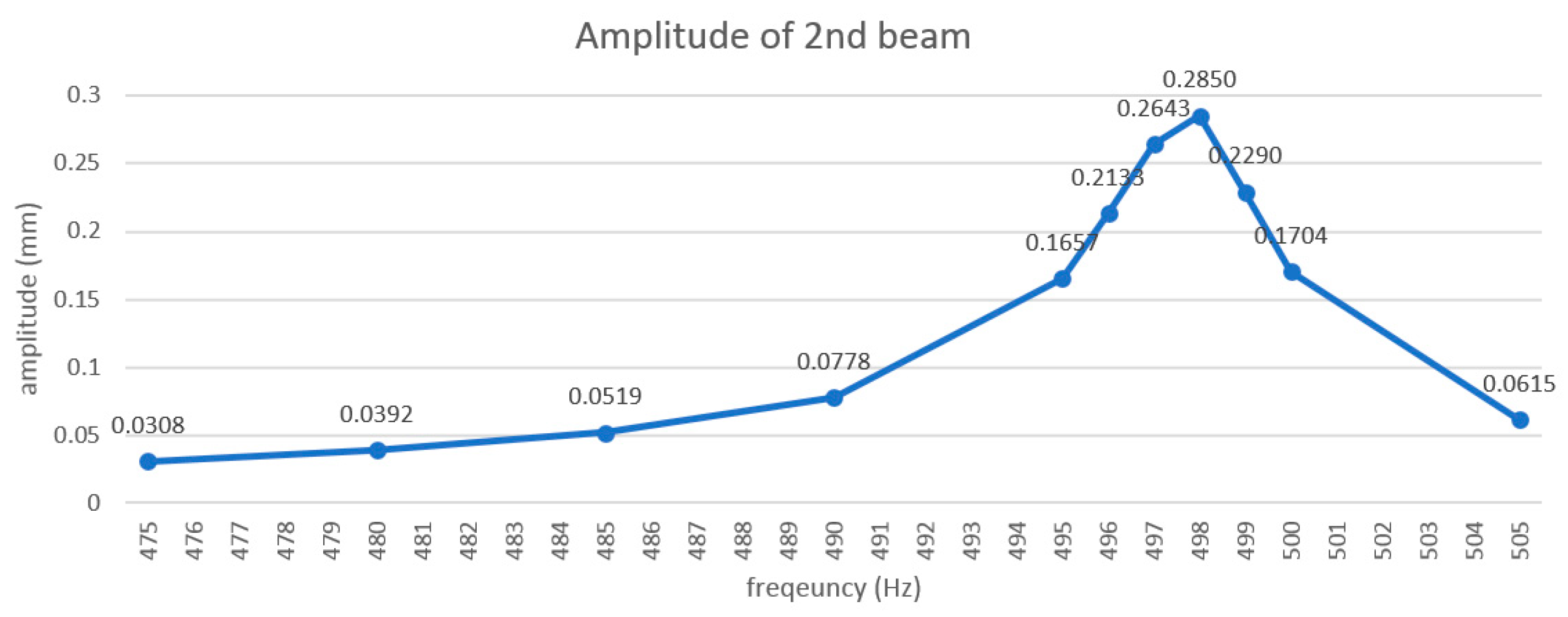
Figure 10 shows the amplitude of the 2nd metal beam depending on the forcing frequency provided by the surface transducer when the silicone rubber beam is 3.4mm long. It is shown that when the silicone rubber beam length is 3.4 mm, the 2nd beam’s resonant frequency is 498 Hz.
After all video files are analyzed, several observations are noted from this experiment:
There are certain lengths of the silicone rubber beams for which the 2nd metal beam vibrates with much lower amplitude. For example, when the silicone rubber beam length is about 10.3~10.7 mm, 5.6~6.7 mm, or 2.1 mm, the amplitude of the beam vibration is greatly decreased. These lengths at which the metal beam vibration is decreased will be referred to here as ‘diminished vibration lengths’.
Between two diminished vibration lengths, the amplitude of metal beam vibration becomes larger and then becomes smaller after a diminished vibration length.
Table 1 shows the amplitude difference of the 2nd metal beam depending on the silicone rubber beam lengths.
The resonant frequency of the 2nd metal beam trends towards the resonant frequency of the beam without the silicone rubber beam, as the silicone rubber beam length becomes shorter. However, when the amplitude of vibration of the metal beam is very small due to the length of the silicone rubber beam, the resonant frequency becomes very different than it was without the rubber beam.
When the silicone rubber beam length is longer than 10mm, the maximum amplitude and resonant frequency of the metal beam cannot be determined, and when the silicone rubber beam length is shorter than 2mm, the vibration of the beam becomes more difficult to perceive by touch.
Silicone rubber beams may absorb the vibration from other metal beams. For example, there are 4 silicone rubber beams attached to the 2nd to 5th metal beams, and there is no silicone rubber beam attached to the 1st beam. When a silicone rubber beam is attached to the 1st beam, the amplitude of 2nd metal beam decreases significantly.
If the length of the 2nd rubber beam is different than the lengths of the other rubber beams, then the frequency response of the 2nd metal beam is very different than it is when every rubber beam has the same length.
Three experiment sets are performed to find the silicone rubber beam length that maximizes the vibrational amplitude of the 2nd metal beam. In these three experiments, the optimal rubber length is found to be 4.3, 4.6, 3.4 mm.
If the difference in length between the 2nd rubber beam and other rubber beams is small, and the length of the 2nd rubber beam is around the length with the maximum amplitude, the vibration result is similar with the case of all silicone rubber beams with the same length. For example, if the difference in the length between the 2nd rubber beam and other rubber beams is around 0.6mm, and the length of the 2nd rubber beam is 3.4 mm, the maximum amplitude and resonant frequency of the 2nd metal beam in both cases are about the same. But the bandwidth is smaller in the case of every beam having same length of silicone rubber beams.
Based on these results, it is hypothesized that the silicone rubber beam has its own resonant frequency, so when the resonant frequency of the silicone rubber beam is similar to the resonant frequency of the metal beam, the amplitude of metal beam vibration is smaller. To verify this assumption, the resonant frequencies of the 2nd silicone rubber beam in 1st and 2nd mode vibration are calculated, as shown in
Table 2.
By comparison of
Table 1 and
Table 2, it is found that when the resonant frequency of the 2nd silicone rubber beam in the 1st or 2nd mode vibration is similar with the resonant frequency of the 2nd metal beam, the metal beam vibration is not observable since the frequencies of two different materials are compensated and offset. However, the calculated resonant frequency of the silicone rubber beam is not exactly the same as the resonant frequency of the metal beam, which was obtained from the experiment, and there is a frequency difference between them. There might be several possible reasons. First, other silicone rubber beams attached to other metal beams could affect the resonant frequency of the 2nd silicone rubber beam since all metal beams are connected by the beam base part. Second, the size effect in micro-mesoscale depending on a silicone rubber beam length difference could affect the resonant frequency of silicone rubber beams, which causes the frequency difference. In microscale, the elastic modulus and damping ratio are changeable due to the size effect [
19]. The further research will be needed to figure out the exact reason for the frequency difference between the frequency of the 2nd metal beam obtained from this experiment and the calculated frequency of the 2nd silicone rubber beam.
In order to utilize silicone rubber beams as a compliant mechanism to increase beam vibration during contact between metal beams and skin, the vibrational characteristics of the silicone rubber beams will need to be incorporated into the metal beam design.
5. Conclusion
In this paper, the haptic display using the resonant vibrotactile microbeam is presented. The concept of the resonant vibrotactile microbeam haptic display is briefly reviewed. All the parameters are considered under the three criteria: maximizing amplitude, minimizing frequency, and minimizing damping ratio of the materials. To solve the micro-meso scale beam vibration stop problem by skin contact, the human skin contact experiments are presented: dry skin contact, wet and soaped skin contact, skin contact to a constraint and metal beam tips, normal force measurement, and skin contact to silicone rubber beam tips attached to metal beam tips. In the skin contact experiment with silicone rubber beams, beam vibration can be perceived when a finger contacts the silicone rubber beams that is attached to the vibrating metal beam. This shows it is beneficial to attach silicone rubber beams to the metal beam tips to solve the user perception problem, in which a vibrating beam stops due to the normal force exerted by a finger when a finger contacts the beam tips. For more information about the effect of the silicone rubber beams on the metal beam vibration depending on the length of silicone rubber beams, forced response experiments for the metal beam are conducted by cutting the silicone rubber beams with some increments.
Further research will be needed to analyze the relationship between beam vibration and silicon rubber vibration numerically. This result can be used to define the efficiency of silicone rubber beam attachment to the metal beam tips in order to solve the user perception problem.
Author Contributions
The authors have contributed equally to the research contained in this paper as follows: conceptualization, D.W. and A.A.S.; methodology, D.W. and A.A.S.; software, D.W. and A.A.S.; validation, D.W.; formal analysis, D.W.; investigation, D.W.; resources, A.A.S.; data curation, D.W.; writing—original draft preparation, D.W.; writing—review and editing, D.W. and A.A.S.; visualization, D.W.; supervision, A.A.S.; project administration, A.A.S..
Funding
This research received no external funding.
Conflicts of Interest
The authors declare no conflict of interest.
References
- Ruspini, D.C.; Kolarov, K.; Khatib, O. The haptic display of complex graphical environments. In Proceedings of the 24th Annual Conference on Computer graphics and Interactive Techniques, Los Angeles, CA, USA, 3–8 August 1997; pp. 345–352. [Google Scholar]
- Kilgour, A.R.; de Gelder, B.; Lederman, S.J. Haptic face recognition and prosopagnosia. Neuropsychologia 2004, 42, 707–712. [Google Scholar] [CrossRef] [PubMed]
- Ur Réhman, S. Expressing Emotions through Vibration for Perception and Control. Ph.D. Thesis, Department of Applied Physics and Electronics, Umeå University, Umeå, Sweden, 2010. [Google Scholar]
- McDaniel, T.; Bala, S.; Rosenthal, J.; Tadayon, R.; Tadayon, A.; Panchanathan, S. Affective haptics for enhancing access to social interactions for individuals who are blind. In Proceedings of the Universal Access in Human-Computer Interaction, Crete, Greece, 22–27 June 2014; pp. 419–429. [Google Scholar]
- D’Angio, P.C. Adaptive and Passive Non-Visual Driver Assistance Technologies for the Blind Driver Challenge®. Ph.D. Thesis, Virginia Tech, Montgomery County, VA, USA, 2010. [Google Scholar]
- Bach-y-Rita, P. Neurophysiological basis of a tactile vision-substitution system. IEEE Trans. Man-Machine Sys. 1970, 11, 108–110. [Google Scholar] [CrossRef]
- Bach-Y-Rita, P.; Collins, C.C.; Saunders, F.A.; White, B.; Scadden, L. Vision Substitution by Tactile Image Projection. Nature 1969, 221, 963–964. [Google Scholar] [CrossRef] [PubMed]
- Bach-y-rita, P. Tactile vision substitution: Past and future. Int. J. Neurosci. 1983, 19, 29–36. [Google Scholar] [CrossRef] [PubMed]
- Grant, P.; Spencer, L.; Arnoldussen, A.; Hogle, R.; Nau, A.; Szlyk, J.; Nussdorf, J.; Fletcher, D.C.; Gordon, K.; Seiple, W. The Functional performance of the brainport v100 device in persons who are profoundly blind. J. Vis. Impair. Blind. 2016, 110, 77–88. [Google Scholar] [CrossRef]
- Danilov, Y.; Tyler, M. Brainport: An alternative input to the brain. J. Integr. Neurosci. 2005, 4, 537–550. [Google Scholar] [CrossRef] [PubMed]
- Nau, A.; Bach, M.; Fisher, C. Clinical tests of ultra-low vision used to evaluate rudimentary visual perceptions enabled by the BrainPort vision device. Transl. Vision Sci. Technol. 2013, 2, 1. [Google Scholar] [CrossRef] [PubMed]
- Bach-y-Rita, P.; Kercel, S.W. Sensory substitution and the human–machine interface. Trends Cogn. Sci. 2003, 7, 541–546. [Google Scholar] [CrossRef] [PubMed]
- Wacker, P.; Wacharamanotham, C.; Spelmezan, D.; Thar, J.; Sánchez, D.A.; Bohne, R.; Borchers, J. VibroVision: An on-body tactile image guide for the blind. In Proceedings of the 2016 CHI Conference Extended Abstracts on Human Factors in Computing Systems; San Jose, CA, USA, 7–12 May 2016; pp. 3788–3791. [Google Scholar]
- Dakopoulos, D.; Bourbakis, N. Towards a 2D tactile vocabulary for navigation of blind and visually impaired. In Proceedings of the IEEE International Conference on Systems, Man and Cybernetics, San Antonio, TX, USA, 11–14 October 2009; pp. 45–51. [Google Scholar]
- Wi, D.; Sodemann, A. Vibration analysis for the development of resonant microbeam high-resolution vibrotactile haptic display. J. Vib. Control 2018, 25, 362–372. [Google Scholar] [CrossRef]
- Wi, D.; Sodemann, A.; Chicci, R. Vibratory haptic feedback assistive device for visually-impaired drivers. In Proceedings of the 2017 IEEE SmartWorld, Ubiquitous Intelligence Computing, Advanced Trusted Computed, Scalable Computing Communications, Cloud Big Data Computing, Internet of People and Smart City Innovation (SmartWorld/SCALCOM/UIC/ATC/CBDCom/IOP/SCI), San Francisco, CA, USA, 4–8 August 2017; pp. 1–5. [Google Scholar]
- Bolanowski, S.J., Jr.; Gescheider, G.A.; Verrillo, R.T.; Checkosky, C.M. Four channels mediate the mechanical aspects of touch. J. Acoust. Soc. Am. 1988, 84, 1680–1694. [Google Scholar] [CrossRef]
- O’Meara, D.M.; Smith, R.M. Static friction properties between human palmar skin and five grabrail materials. Ergonomics 2001, 44, 973–988. [Google Scholar] [CrossRef]
- Abazari, A.M.; Safavi, S.M.; Rezazadeh, G.; Villanueva, L.G. Modelling the size effects on the mechanical properties of micro/nano structures. Sensors 2015, 15, 28543–28562. [Google Scholar] [CrossRef] [PubMed]
© 2019 by the authors. Licensee MDPI, Basel, Switzerland. This article is an open access article distributed under the terms and conditions of the Creative Commons Attribution (CC BY) license (http://creativecommons.org/licenses/by/4.0/).


