Article

Novel Approaches for Intensifying Negative C60 Ion Beams Using Conventional Ion Sources Installed on a Tandem Accelerator

1
Takasaki Advanced Radiation Research Institute, National Institutes for Quantum and Radiological Science and Technology (QST), 1233 Watanuki, Takasaki, Gunma 370-1292, Japan
2
Oarai Research and Development Institute, Japan Atomic Energy Agency (JAEA), 4002 Narita, Oarai, Ibaraki 311-1393, Japan
*
Author to whom correspondence should be addressed.
Quantum Beam Sci. 2020, 4(1), 13; https://doi.org/10.3390/qubs4010013
Submission received: 24 December 2019 / Revised: 22 February 2020 / Accepted: 24 February 2020 / Published: 2 March 2020
(This article belongs to the Special Issue Quantum Beams Applying to Innovative Industrial Materials)

Abstract

:
We developed novel methods for producing negative C60 ion beams at the accelerator facility Takasaki Ion Accelerators for Advanced Radiation Application (TIARA) to increase the current intensity of swift C60 ion beams accelerated to the MeV energy region using a tandem accelerator. We produced negative C60 ion beams with an intensity of 1.3 µA, which is several tens of thousands of times greater than the intensity of beams produced using conventional methods based on the Cs sputtering process. These beams were obtained by temporarily adding an ionization function based on electron attachment to an existing ion source that is widely used in tandem accelerators. The high-intensity swift C60 ion beams can be made available relatively easily to institutes that have tandem accelerators and ion sources of the type used at TIARA because there is no need to change existing ion sources or install new ones.

1. Introduction

The production of C60 ion beams in the MeV energy region using tandem accelerators in the 1990s enabled some physical phenomena based on the interaction of swift C60 ions with solids that were not possible using monatomic ion bombardments. For example, ion track formation on Si wafers, which had never been observed in monoatomic heavy ion bombardment even at GeV energies, was achieved through C60 ions at an energy of 30 MeV [1]. Several reports have been published on ion track formation for various materials through bombardment with C60 ion at MeV energies [2,3,4,5,6,7]. While basic research had been actively conducted on local phenomena caused by individual C60 ion projectiles (such as ion track formation), there has been little research done on their industrial applications, such as modification or analysis of material surfaces using C60 ion beams at MeV energy levels. This gap can be attributed to the low intensity of MeV C60 ion beams.
A tandem accelerator was used to accelerate C60 ion beams to the MeV energy region for the first time at IPN, Orsay [8]. Thereafter, MeV C60 ion beams were available for ion irradiation experiments at research facilities equipped with tandem accelerators in Europe [9,10]. In such facilities, negative C60 ion beams provided to a tandem accelerator were generated using a Cs sputter negative ion source, which is generally used to produce heavy negative ion beams of monatomic and small polyatomic species. Therefore, though it is simple to produce negative C60 ion beams, most of the C60 molecules dissociate due to sputtering with Cs ions. Thus, the beam intensity of C60 ions extracted from ion sources without dissociation is at most about 100 pA. Furthermore, many negative C60 ions dissociate upon collision with the charge exchange gas at the high voltage terminal of the tandem accelerator. As a result, the intensity of C60 ion beams that is finally transported to a target is less than 1 pA. Hence, most previous experimental studies using such low intensity beams would have been limited to basic researches focused on the observation of phenomena induced by individual C60 ion impacts. If swift C60 ion beams are made usable at high intensity through electrostatic accelerators, we can expect to rediscover new irradiation effects and physical phenomena, as well as its usefulness in ion-beam applications through macroscopic observations using high fluence irradiation of C60 ion beams.
The usefulness of large cluster ions, such as C60 ions [11,12,13], gas cluster ions [14], metal cluster ions, etc. [15], has already been demonstrated in the keV energy region through their use as primary ions in secondary ion mass spectrometry (SIMS). Various primary cluster ions have been shown to enhance the emission yield of intact large molecular ions from specimens, (e.g., organic polymer materials or biomolecules) compared to monatomic primary ions. Furthermore, it has been confirmed that the emission yield of large molecular ions increases with the energy of C60 primary ions [16,17]. Combining SIMS with swift C60 ion beams might offer a powerful tool for the analysis of organic polymer materials, organic and inorganic composites, and biomolecular samples, etc. To establish this technology, it is necessary to increase the intensity of swift C60 ion beams. In addition, it is important to improve the ease of obtaining such intense beams to encourage growth in this research field. In this article, we report the ionization methods we developed for effective producing negative C60 ions without dissociation, using an ion source that is generally installed on tandem accelerators. We outline the conventional method for generating negative C60 ion beams, and present novel and simple methods for obtaining high-intensity MeV C60 ion beams.

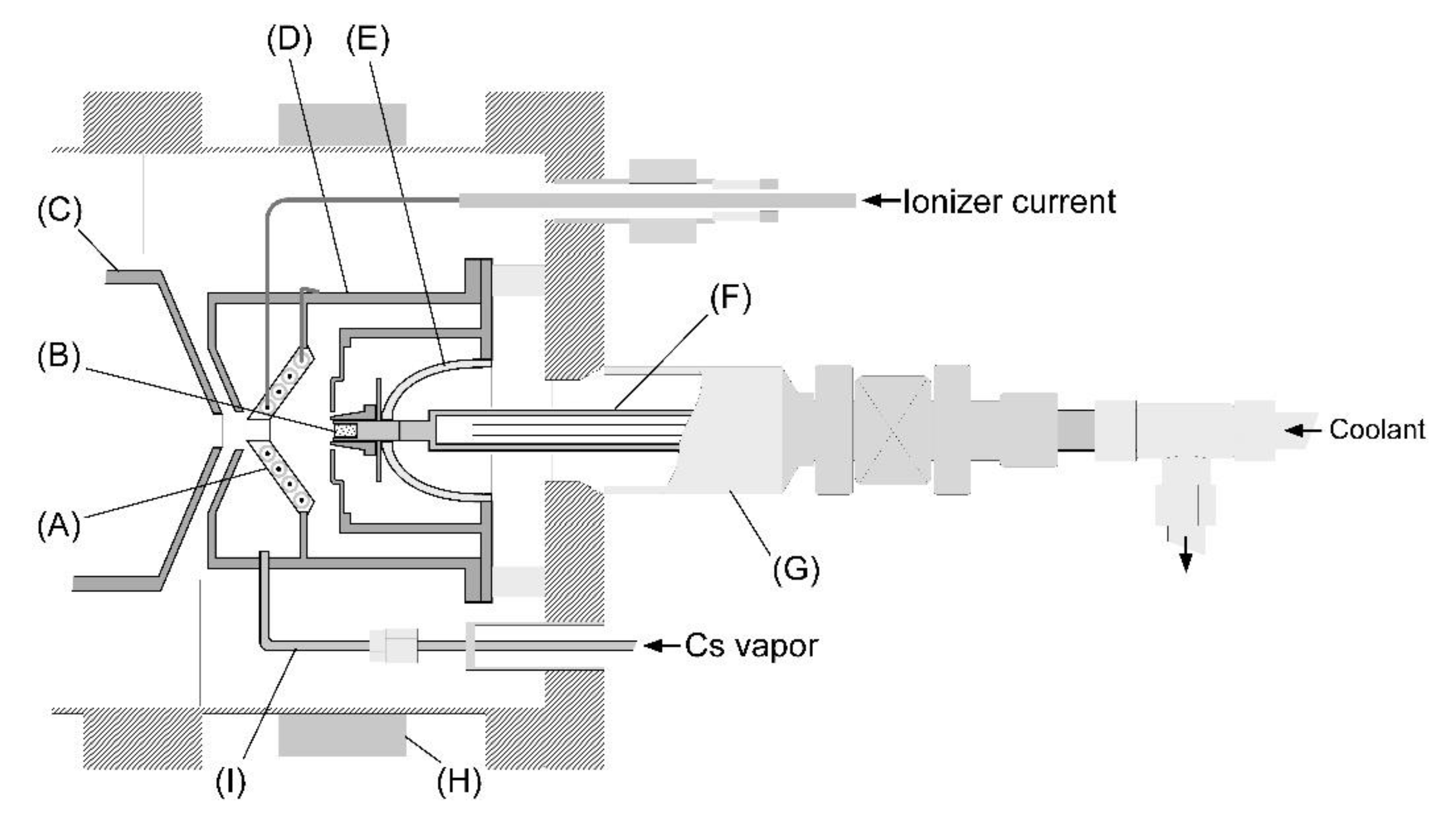
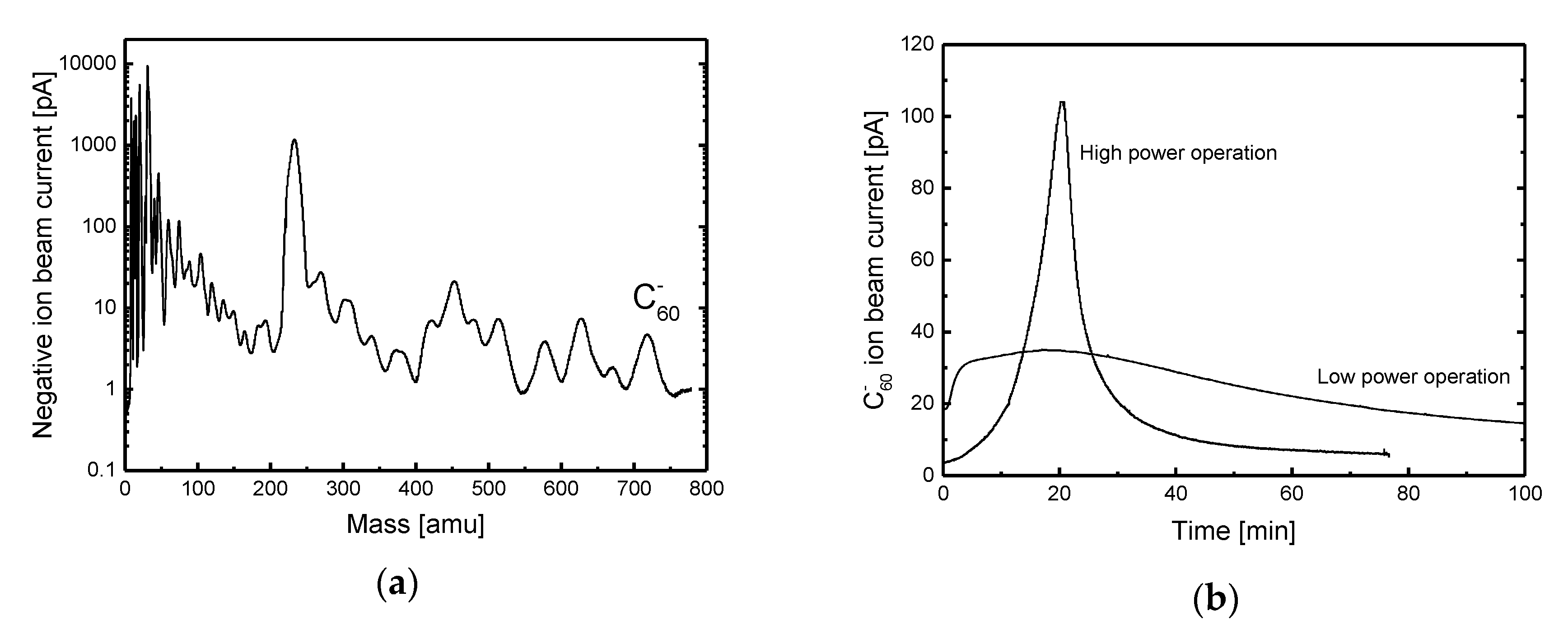
2. Conventional Method (Cs Sputter)

A Cs sputter ion source is commonly used to produce different negative atomic and molecular ions (excluding noble gas samples) that are provided to tandem accelerators. Cs sputter ion sources are broadly classified into two types based on their sputtering methods: Cs ion gun and spherical or cylindrical surface ionizer types [18,19].
We employed the ionizer-type Cs sputter ion source (SNICS ΙΙ, National Electrostatics Corporation (NEC), Wisconsin, W.I., USA)) connected to a 3-MV tandem accelerator (9SDH-2, NEC) to produce negative C60 ion beams based on conventional methods at the Takasaki Ion Accelerators for Advanced Radiation Application (TIARA) based at the National Institutes for Quantum and Radiological Science and Technology (QST-Takasaki, Takasaki Gunma, Japan). A schematic of the SNICS II ion source at TIARA is shown in Figure 1 [20]. Cs vapor is produced in the cesium oven and injected into the ionizer chamber. Some of the vapor is ionized by heat from the hot ionizer surface and some of the vapor condenses on the surface of the sputter cathode. C60 powder with a purity of 99.5% is compressed into the cylindrical copper holder as a sputter cathode. The Cs ions accelerate toward the sputter cathode and collide with the C60 particles through the condensed cesium layer. Most of the C60 particles are dissociated by Cs ion sputtering, but a few remain intact. Electric field from the extraction electrode is used to extract the intact C60 particles that were negatively ionized without dissociation from the ion source, together with several fragment ions. Figure 2a shows the mass spectrum of negative ion beams produced from the pure C60 cathode by the Cs sputter method. The horizontal axis in the figure represents mass number, calculated from measured values of the deflection magnetic field of an analyzing magnet placed downstream of the ion source. As can be observed from the figure, fragment ions account for most of the beam; C60 ions contribute only 1% or less of the total ions. Ion production tests using different solidification pressures of C60 powder shows that a negative C60 ion beam of about 100 pA was obtained at a solidification pressure of 2 t/cm2, as shown in Figure 2b. However, as more fragments accumulate on the cathode surface with increasing the number of Cs ion bombardment, the C60 ion beam current decreases rapidly, dropping below 10 pA in just tens of minutes. The rapid changes in the beam current can be inhibited by adjusting the ionization rate of cesium by the power supplied to the ionizer. However, the beam current was very low, and the lifetime of the sputter cathode was not long for all of the operations.

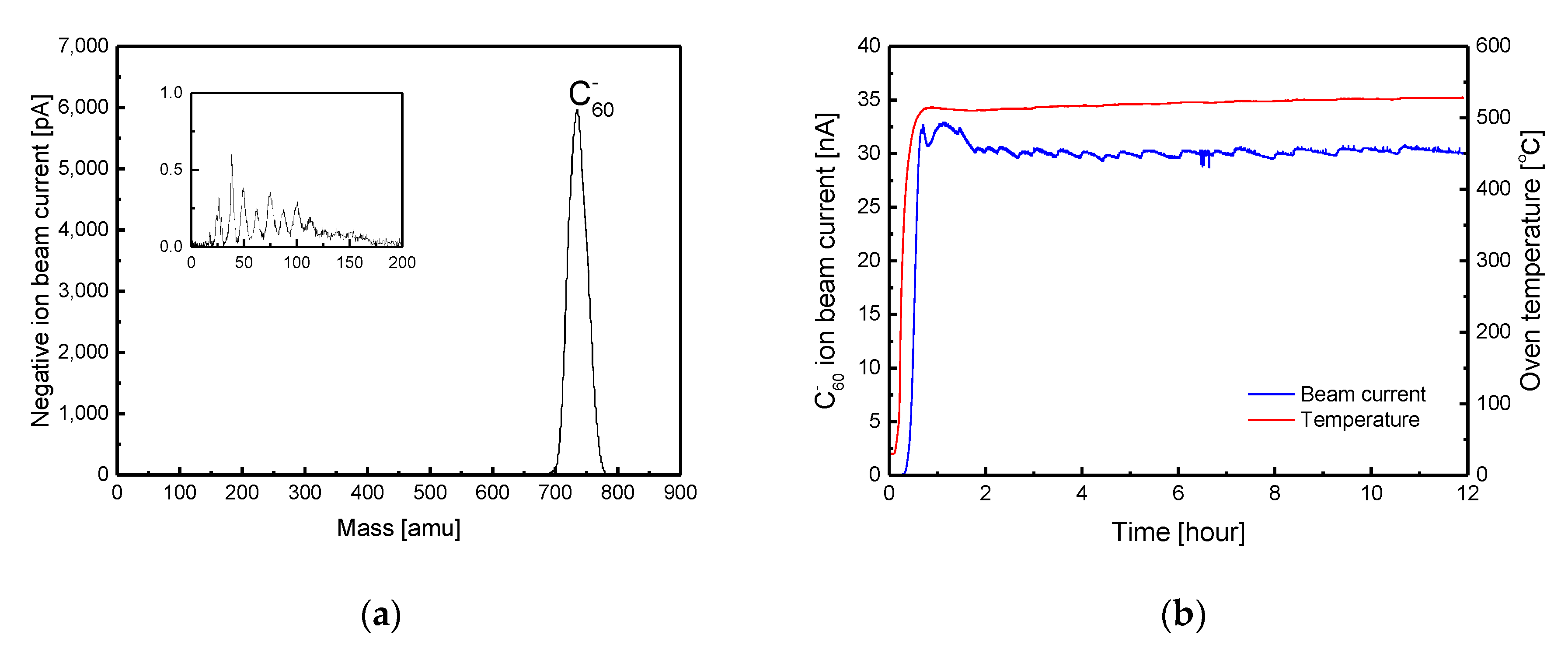
3. Electron Attachment Method
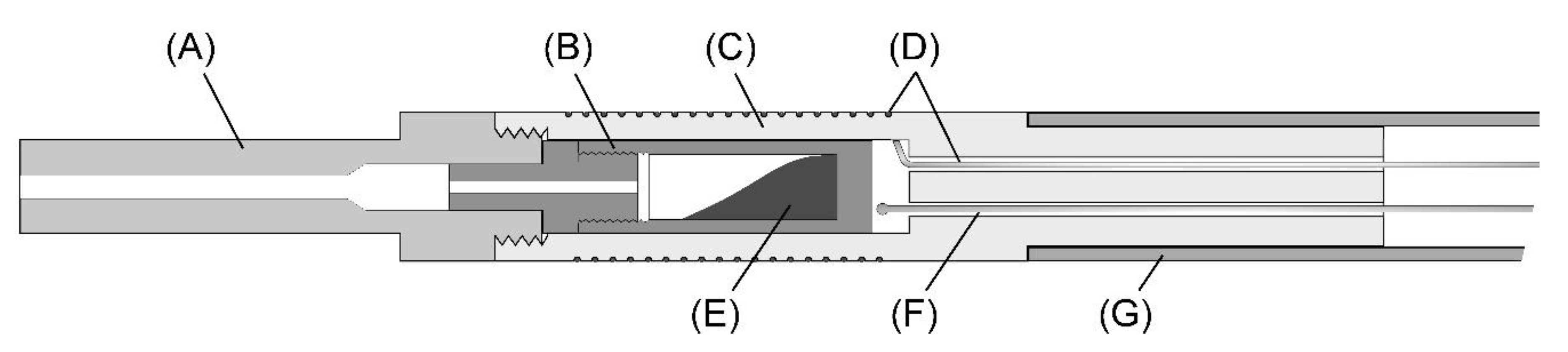
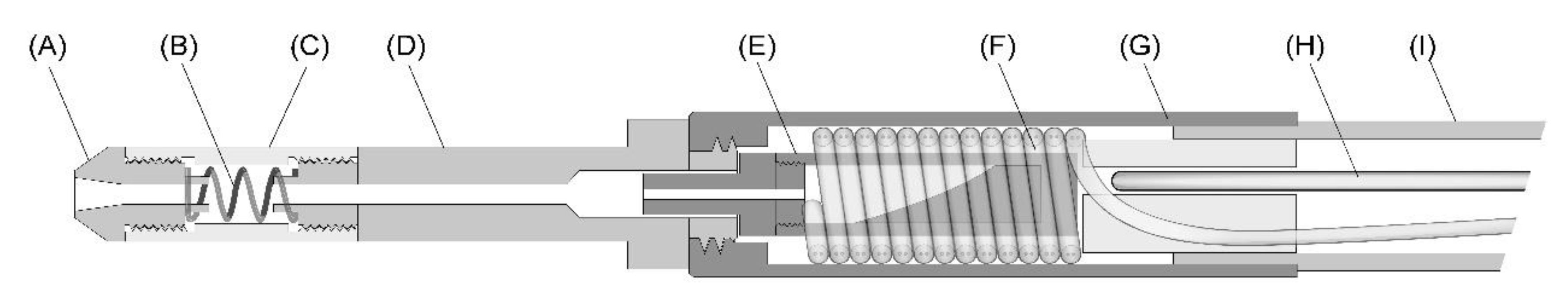
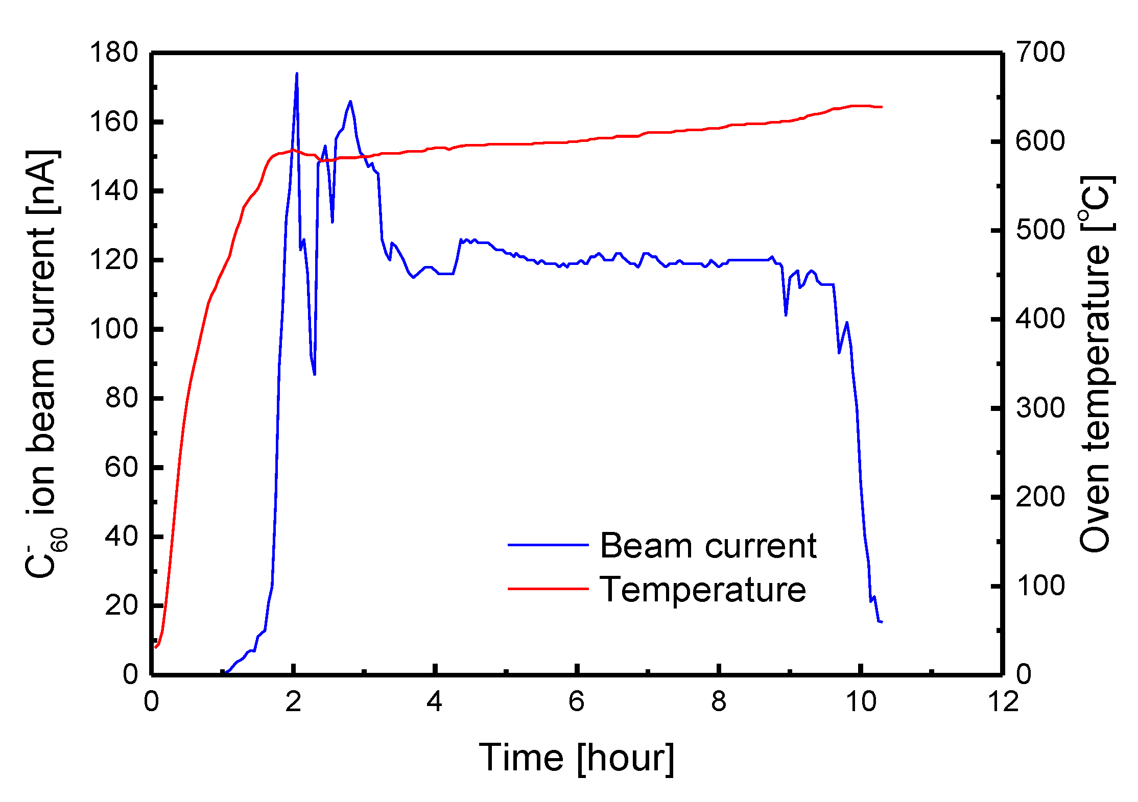
A characteristic of fullerenes (e.g. C60, C70, etc.) is their strong affinity to electrons [21]. They have large attachment cross-sections for low energy electrons in the eV range [22,23]. Several negative fullerene ion sources have been developed using this characteristic. For example, source types in which free electrons attach directly to the neutral fullerenes during their near-grazing scattering from a heated material surface [24], and types in which they attach to the fullerenes in plasma [25]. Though these methods can be used to produce C60 ions effectively, none of these are ion sources developed in order to produce negative ion beams that are used in the acceleration process at tandem accelerators. Therefore, it will not be easy to install these ion sources on a tandem accelerator. We developed and implemented two novel and simple methods described below to produce negative C60 ions based on thermal electron attachment using an existing ion source connected with the tandem accelerator.

3.1. The Oven Rod

Figure 3 shows a cross section of the oven rod. This production method uses thermal electrons emitted from the surface of ionizers in Cs sputter ion sources, as shown in Figure 1. These electrons were not useful in this ion source in the original ion production process. The oven rod is equipped with a small oven for C60 sublimation to give it similar external dimensions as the cathode holder so that it can be inserted into the ion source instead of the cathode holder. A C60 powder sample in a carbon crucible loaded in a ceramic insulator winding on a Ta heater wire can conduct heat up to 700 °C. The Ta wire and a thermocouple are connected through a 1/2-inch stainless-steel pipe to a DC power source and a data acquisition module in the atmosphere via a vacuum feed at the end of the rod. Some of the sublimated C60 particles flowing to the exit of the ionizer chamber capture thermal electrons emitted from the surface of the ionizer, which is heated to 1000 °C or higher. A part of these particles are accelerated by the electric field generated by the extraction electrode toward an analyzing magnet via an acceleration tube. The mass spectrum of the negative ion beam and the intensity of the negative C60 ion beam current are shown as functions of time in Figure 4a,b, respectively. Though a few fragment ions dissociated by the heat of the ionizer were observed, the ion beam was mostly dominated by the C60 ions. At constant oven temperature, the current of the negative C60 ion beam decreases slowly. Therefore, increasing the oven temperature in steps of 1 °C when the beam current decreases by a few nA ensures a stable current intensity of about 30 nA over 10 hours.

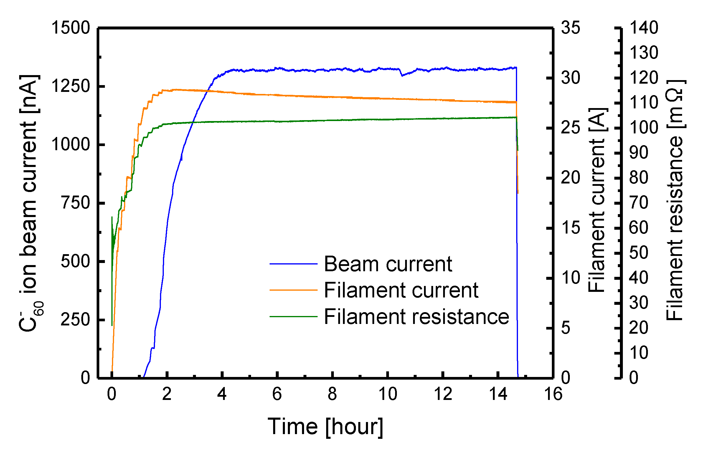
3.2. The Oven Rod with Built-In Source of Electrons

A cross-section of the oven rod equipped with a filament as an electron source is shown in Figure 5. A part of its nozzle was modified to an insulating ceramic tube with an inner diameter of 5 mm to build in a helical tungsten filament (1% Th-W with a diameter of 0.8 mm). In addition, the carbon crucible is housed in a helical cylindrical heater shaped by a 1.6 mm outer diameter sheathed heater (Okazaki Manufacturing Co., Hyogo, Japan). The heater is entirely covered with a Cu-W alloy shell. This oven rod is inserted into the Cs sputter ion source until the tip of the nozzle is in full contacts with the surface of the ionizer. Filament current was supplied via a stainless-steel pipe and the Cu-W alloy shell in vacuum from the end of the rod in the atmosphere. The current from the filament returns to a DC power source through the metal plate of the ionizer, the Cs vapor line, and the vacuum flange. Some of the sublimated C60 particles individually capture some of the thermal electrons emitted from the filament in the narrow space inside the nozzle. These are extracted as a negative ion beam from the ion source by the electric field of the extractor electrode. The intensity of the negative C60 ion beam accounts for > 90% of the total extracted ion beam. While negative ions of chlorine that might have been mixed with the C60 sample during the purification process was contained in the beam immediately after production, fragment ions of C60 that would have been thermally dissociated at the surface of the filament were hardly detected. Figure 6 shows a typical example of the results of the negative C60 ion beam production test. The beam current intensity fluctuates significantly for a while after supplying current to the filament. It is considered that the electron emission yield from the filament was not stable due to fluctuation of the contact resistance of the filament arising from its own thermal expansion. After the filament resistance became stable to some extent, the beam current was kept nearly stable at about 120 nA for several hours by gradually increasing the oven temperature at a rate of about 5 °C per hour; at this time, the power supplied to the filament was nearly constant at 110 W. Further increasing the power supply to the filament also increases the intensity of the beam current. However, if the filament temperature becomes too high, it eventually causes a severe drop in the beam current. Figure 7 shows photographs of the filaments before and after use for a power of 150 W for six hours. Under this condition, the filament temperature is estimated to have exceeded 1500 °C where carbide formation would start at its surface. As can be seen from the photographs, after use, the filament is thickly covered with material comprising mostly carbides derived from molecular C60. We believe that the drop in the beam current is due to the decay in the electron emission yield induced by extraneous materials on the surface of the filament.
Experimental results obtained during the production of the negative C60 ion beam using suitable quantities of Cs compound (CsI) are presented in Figure 8. The beam current intensity increases by an order of magnitude compared to samples without the CsI, despite the relatively low power of about 85 W supplied to the filament. In addition, there was no significant fluctuation in the intensity of the beam current as was observed in Figure 6, and the filament surface after use had almost no carbides. We believe that the effects of cesium and iodine and the fine operational techniques resulted in the highly intense and stable negative C60 ion beam. The CsI sublimates at a temperature slightly lower than that of the C60 flowing in the nozzle prior the C60 vapor. Some of the Cs that thermally dissociated in the nozzle would effectively lower the work function of the filament surface and substantially increase the number of electrons emitted from the surface. In addition, the cross-section of electron capture by the C60 particles interacting with the inner wall of the nozzle would be enhanced because the cesium also reduces the work function of the inner wall surface. Similarly, the iodine (which is also used in halogen cycle lamps) might contribute in maintaining the filament surface and extend the lifetime of the filament. A possible reason for the enhanced stability of the beam current is that the Cs enabled the production of extremely high intensity beams, even though the filament power was low, thereby inhibiting large fluctuations in the resistance of the filament. Operational techniques in which the filament current is controlled delicately are also required to keep the beam intensity constant over long periods of time. The filament current needs to be lowered step by step because if the filament current is left constant, the resistance of the filament increases gradually with temperature, eventually causing the intensity of the beam current to become unstable. Thus, it is important that the resistance value remains nearly constant to obtain the stable beam current, as shown in Figure 8.
Finally, we describe the transmission of C60 ion beams through the tandem accelerator to obtain higher intensity current, MeV C60 ion beams. In generally, to accelerate monatomic ion beams, we use nitrogen (N2) gas as a stripper gas in the charge exchange section of the tandem accelerator. However, the transmission experiments conducted on several gaseous species for cluster ion incidence demonstrated that higher transmission could be achieved when smaller-sized gases is used, e.g., helium [26]. Therefore, helium gas is recommended as a stripper gas for the C60 ion beams. By adjusting the helium gas pressure suitable for C60 ion acceleration, the transmission ratio can be doubled compared to when N2 gas is used.

4. Conclusions

We demonstrated two methods for producing negative C60 ion beams based on the electron attachment process, using an existing Cs sputter-type ion source without modification. One method makes use of thermal electrons emitted from an ionizer in the ion source. Through this method, we easily obtained a beam intensity of about 30 nA using the oven rod with a simple structure. Another method that uses the oven rod equipped with a filament as an electron source is inferior, in terms of operability and maintainability, to the method that uses the simple oven rod, while it has a great advantage of being able to produce a beam current of 1 µA or higher. The original operation of the Cs sputter negative ion source to produce general heavy ion beams can be performed by simply replacing the oven rod with the cathode holder. Therefore, in accelerator facilities that operate this type of ion source, experiments requiring high fluence irradiation of MeV C60 ion beams can be performed with low capital investment as there is no need to install of new ion sources in an incident beam line of the tandem accelerator.

Author Contributions

Conceptualization, methodology, software, and writing: A.C.; data curation and formal analysis: A.C. and A.U.; investigation and resources: K.Y. and Y.H.; project administration and supervision: K.N. and Y.S. All authors have read and agreed to the published version of the manuscript.

Funding

This study was partially supported by JSPS KAKENHI grant numbers 25820452 and 18K18309.

Acknowledgments

The authors thank the technical staff of the 3-MV tandem accelerator in TIARA, QST for their skillful support.

Conflicts of Interest

The authors declare no conflict of interest.

References

  1. Dunlop, A.; Jaskierowicz, G.; Della-Negra, S. Latent track formation in silicon irradiation by 30 MeV fullerenes. Nucl. Instr. Meth. Phys. Res. B 1998, 146, 302–308. [Google Scholar] [CrossRef]
  2. Dammak, H.; Dunlop, A.; Lesueur, D.; Brunelle, A.; Della-Negra, S.; Le Beyec, Y. Tracks in metals by MeV fullerenes. Phys. Rev. Lett. 1995, 74, 1135–1138. [Google Scholar] [CrossRef] [PubMed]
  3. Barlo Daya, D.D.N.; Hallén, A.; Eriksson, J.; Kopniczky, J.; Papaléo, R.; Reimann, C.T.; Håkansson, P.; Sundqvist, B.U.R.; Brunelle, A.; Della-Negra, S. Radiation damage features on mica and L-valine probed by scanning force microscopy. Nucl. Instr. Meth. Phys. Res. B 1995, 106, 38–42. [Google Scholar] [CrossRef]
  4. Fink, D.; Vacik, J.; Klett, R.; Chadderton, L.T.; Hnatowicz, V. Doping of 20 MeV fullerene ion tracks in polyimide. Nucl. Instr. Meth. Phys. Res. B 1996, 119, 591–595. [Google Scholar] [CrossRef]
  5. Döbeli, M.; Ames, F.; Musil, C.R.; Scandella, L.; Suter, M.; Synal, H.A. Surface tracks by MeV C60 impacts on mica and PMMA. Nucl. Instr. Meth. Phys. Res. B 1998, 143, 503–512. [Google Scholar] [CrossRef]
  6. Dhamodaran, S.; Pathak, A.P.; Dunlop, A.; Jaskierowicz, G.; Della Negra, S. Energetic cluster irradiation of InP. Nucl. Instr. Meth. Phys. Res. B 2007, 256, 229–232. [Google Scholar] [CrossRef]
  7. El-Said, A.S. Tracks of 30-MeV C60 clusters in yttrium iron garnet studied by scanning force microscopy. Nucl. Instr. Meth. Phys. Res. B 2009, 267, 953–956. [Google Scholar] [CrossRef] [Green Version]
  8. Della-Negra, S.; Brunelle, A.; Le Beyec, Y.; Curaudeau, J.M.; Mouffron, J.P.; Waast, B.; Håkansson, P.; Sundqvist, B.U.R.; Parilis, E. Acceleration of C60n+ molecules to high energy. Nucl. Instr. Meth. Phys. Res. B 1993, 74, 453–456. [Google Scholar] [CrossRef]
  9. Ames, F.; Döbeli, M.; Musil, C.R.; Nebiker, P.W.; Scandella, L.; Suter, M.; Synal, H.A. Acceleration of clusters, collision induced charge exchange at MeV energies and applications for materials science. Nucl. Instr. Meth. Phys. Res. B 1996, 112, 64–67. [Google Scholar] [CrossRef]
  10. Tomaschko, C.; Kügler, R.; Schurr, M.; Voit, H. MeV cluster ions from the Erlangen tandem accelerator. Nucl. Instr. Meth. Phys. Res. B 1996, 117, 199–204. [Google Scholar] [CrossRef]
  11. Weibel, D.; Wong, S.; Lockyer, N.; Blenkinsopp, P.; Hill, R.; Vickerman, J.C. A C60 primary ion beam system for time of flight secondary ion mass spectrometry: Its development and secondary ion yield characteristics. Anal. Chem. 2003, 75, 1754–1764. [Google Scholar] [CrossRef] [PubMed]
  12. Sun, S.; Szakal, C.; Roll, T.; Mazarov, P.; Wucher, A.; Winograd, N. Use of C60 cluster projectiles for sputter depth profiling of polycrystalline metals. Surf. Interface Anal. 2004, 36, 1367–1372. [Google Scholar] [CrossRef]
  13. Fahey, A.J.; Gillen, G.; Chi, P.; Mahoney, C.M. Performance of a C60+ ion source on a dynamic SIMS instrument. Appl. Surf. Sci. 2006, 252, 7312–7314. [Google Scholar] [CrossRef]
  14. Toyoda, N.; Matsuo, J.; Aoki, T.; Yamada, I.; Fenner, D.B. Secondary ion mass spectrometry with gas cluster ion beams. Appl. Surf. Sci. 2003, 203–304, 214–218. [Google Scholar] [CrossRef]
  15. Rickman, R.D.; Verkhoturov, S.V.; Parilis, E.S.; Schweikert, E.A. Simultaneous ejection of two molecular ions from keV gold atomic and polyatomic projectile impacts. Phys. Rev. Lett. 2004, 92, 047601. [Google Scholar] [CrossRef]
  16. Hirata, K.; Saitoh, Y.; Chiba, A.; Adachi, M.; Yamada, K.; Narumi, K. Development of secondary ion mass spectroscopy using medium energy C60 ion impact. Nucl. Instr. Meth. Phys. Res. B 2008, 266, 2450–2452. [Google Scholar] [CrossRef]
  17. Hirata, K.; Saitoh, Y.; Chiba, A.; Yamada, K. Narumi, Surface-sensitive chemical analysis of organic insulating thin films using negative secondary ions induced by medium energy C60 impacts. Appl. Phys. Expr. 2011, 4, 116202. [Google Scholar] [CrossRef]
  18. Middleton, R. A survey of negative ions from a cesium sputter source. Nucl. Instr. Meth. 1977, 144, 373–399. [Google Scholar] [CrossRef]
  19. Middleton, R. A versatile high intensity negative ion source. Nucl. Instr. Meth. 1983, 214, 139–150. [Google Scholar] [CrossRef]
  20. Rathmell, R.D.; Norton, G.A. Production MeV ion implanters for energies from 200 keV to 4MeV. Nucl. Instr. Meth. Phys. Res. B 1987, 21, 270–273. [Google Scholar] [CrossRef]
  21. Lezius, M.; Scheier, P.; Märk, T.D. Free electron attachment to C60 and C70. Chem. Phys. Lett. 1993, 203, 232–236. [Google Scholar] [CrossRef]
  22. Jaffke, T.; Illenberger, E.; Lezius, M.; Matejcik, S.; Smith, D.; Märk, T.D. Formation of C60 and C70 by free electron capture. Activation energy and effect of the internal energy on lifetime. Chem. Phys. Lett. 1994, 226, 213–218. [Google Scholar] [CrossRef]
  23. Prabhudesai, V.S.; Nandi, D.; Krishnakumar, E. Low energy electron attachment to C60. Eur. Phys. J. D 2005, 35, 261–266. [Google Scholar] [CrossRef]
  24. Bekkerman, A.; Tsipinyuk, B.; Kolodney, E. Thermally activated decay channels of superhot C60: Delayed electron emission and dissociative attachment studied by hyperthermal negative surface ionization. Int. J. Mass Spectrom. 1999, 187, 773–786. [Google Scholar] [CrossRef]
  25. Koda, D.; Kuninaka, H.; Tsukizaki, R. Demonstration of negative fullerene ion thruster combined with positive xenon ion thruster. Trans. JSASS Aerosp. Technol. Japan 2016, 14, 203–208. [Google Scholar] [CrossRef] [Green Version]
  26. Saitoh, Y.; Chiba, A.; Narumi, K. Transmission of cluster ions through a tandem accelerator of several stripper gases. Rev. Sci. Instr. 2009, 80, 106104. [Google Scholar] [CrossRef]
Figure 1. Schematic diagram of the cesium sputter ion source (SNICS ΙΙ, NEC). (A) Ionizer: conical metal plates with built-in a spiral heater wire. (B) Sputter cathode: a target sample compressed into the cylindrical copper holder setting on a tip of the cathode holder. (C) Extractor electrode. (D) Ionizer chamber: metal cylindrical chamber electrically connected to the base flange via the Cs line. (E) Internal cathode insulator. (F) Cathode holder: a 1/2-inch metal pipe with cooling function. (G) External cathode insulator. (H) Electron suppression magnets: a source of magnetic field suppressing leakage of electrons from the ionizer chamber. (I) Cs vapor line.
Qubs 04 00013 g001
Figure 2. Example results of negative C60 ion beam production using conventional methods (Cs sputter method): (a) mass spectrum of negative ions in a beam extracted from an ion source; (b) negative C60 ion beam currents as a function of time. The two beam currents as a function of time in (b) show the results when a different power supplied to the ionizer.
Qubs 04 00013 g002
Figure 3. Cross section of the oven rod. (A) Tungsten nozzle: the inner diameter of 2 mm. (B) Carbon crucible. (C) Ceramic insulator (BN). (D) Ta wire: spirally wounding along the groove on the surface of the ceramic insulator. (E) C60 powder sample. (F) Thermocouple. (G) Half-inch diameter stainless-steel pipe.
Qubs 04 00013 g003
Figure 4. Example results of negative C60 ion beam production using the oven rod: (a) mass spectrum of negative ions contained in beam extracted from the ion source; (b) negative C60 ion beam current (blue line) and oven temperature (red line) as a function of time. The inset in (a) is an expanded vertical scale for a better view of the fragment ions.
Qubs 04 00013 g004
Figure 5. Cross section of the oven rod with built-in electron source. (A) Tungsten nozzle tip cap assembly. (B) Spiral tungsten filament: 1% Th-W wire with a diameter of 0.8 mm. (C) Electron attachment cell: cylindrical ceramic insulator with a length of 19 mm and inner diameter of 5 mm. (D) Tungsten nozzle base assembly. (E) Carbon crucible. (F) Micro-heater: spiral-shaped metal sheathed heater with an outer diameter of 1.6 mm. (G) Cu-W alloy cylindrical shell. (H) Sheathed thermocouple. (I) Half-inch diameter stainless-steel pipe.
Qubs 04 00013 g005
Figure 6. Example results of negative C60 ion beam production using an oven rod with a built-in electron source: the negative C60 ion beam current (blue line) and oven temperature (red line) as functions of time.
Qubs 04 00013 g006
Figure 7. Photographs of the W-filament: (a) before use; (b) filament debris after beam production with a 150-W power supplied to the filament for six hours.
Qubs 04 00013 g007
Figure 8. Experimental results for the negative C60 ion beam production with a C60 sample containing CsI using an oven rod with a built-in electron source. The blue, orange, and green lines represent the time evolutions of the negative C60 ion beam current, the filament current, and the filament resistance, respectively.
Qubs 04 00013 g008

