Article

The Influence of Soil Deformability on the Seismic Response of 3D Mixed R/C–Steel Buildings

by
Paraskevi K. Askouni
Department of Civil Engineering, University of Patras, 26500 Patras, Greece
Infrastructures 2024, 9(5), 80; https://doi.org/10.3390/infrastructures9050080
Submission received: 5 April 2024 / Revised: 26 April 2024 / Accepted: 1 May 2024 / Published: 4 May 2024

Abstract

:
Following effective seismic codes, common buildings are considered to be made of the same material throughout the story distribution and based on an ideal rigid soil. However, in daily construction practice, there are often cases of buildings formed by a bottom part constructed with reinforced concrete (r/c) and a higher steel part, despite this construction type not being recognized by code assumptions. In addition, soil deformability, commonly referred to as the Soil–Structure Interaction (SSI), is widely found to affect the earthquake response of typical residence structures, apart from special structures, though it is not included in the normative design procedure. This work studies the seismic response of in-height mixed 3D models, considering the effect of sustaining deformable ground compared to the common rigid soil hypothesis, which has not been clarified so far in the literature. Two types of soft soil, as well as the rigid soil assumption, acting as a reference point, are considered, while two limit interconnections between the steel part on the concrete part are included in the group analysis. The possible influence of the seismic orientation angle is explored in the analysis set. Selected numerical results of the dynamic nonlinear analyses under strong near-fault ground excitations were plotted through dimensionless parameters to facilitate an objective comparative discussion. The effect of SSI on the nonlinear performance of three-dimensional mixed models is identified, which serves as the primary contribution of this work, making it unique among the numerous research works available globally and pointing to findings that are useful for the enhancement of the seismic rules regarding the design and analysis of code-neglected mixed buildings.

1. Introduction

The normative common building seismic design mainly involves the same structural material throughout the entire building, which rests on ideal rigid supporting soil, following the rules of [1,2,3]. The combination of these two custom hypotheses raises the question of what the impact of ground deformability would be on the seismic behavior of “mixed” models [4]; this has not been precisely investigated in the literature, to the best of the author’s knowledge, in terms of building structural materials. Thus, it is assessed herein considering buildings constructed with reinforced concrete for the lower part and structural steel for the higher part. The related research works mentioned below, selected from the available global literature, are notable given their scientific connection with the current subject.
This work involves the usual practice of combining a lower reinforced concrete (r/c) building part supporting an upper steel one with similar in-plan perimetrical dimensions, forming a “mixed” building type. Mixed buildings are generally found to be attractive because of their lower self-weight and shorter construction time for the steel part, as compared with the r/c one, despite the absence of specific corresponding rules for the applicable regulations, e.g., [1,2,3]. The described mixed-in-height structures can be seen in daily construction cases related to projects based on renovating, redesigning, or updating the structural function of buildings. A preliminary research analysis of mixed frames was performed by Maley et al. [4], who showed that usual design procedures can be applied in mixed frames considering the usual rigid soil assumption, but it was found that more research is necessary to investigate their nonlinear response to an improvement in seismic performance. The mixed structures investigated here do not interfere with “secondary structures” [5], indicating smaller in-weight and in-plan structures that are attached to the main structure, not designed for earthquake resistance, and built with low-quality materials. The combination of different materials in the current models is examined in the vertical direction at the story level. Similarly, selected mixed 3D frames have been designed as new constructions [1,2,3] and examined by nonlinear time history (NLTH) analysis, considering the typical rigid soil assumption under strong earthquakes, as presented by Askouni and Papagiannopoulos [6,7,8]. For the select mixed 3D models analyzed by Askouni [9], which rested on rigid soil, the r/c part was considered as an older construction, while the steel part was considered as a custom construction, with sequential earthquake excitations showing a possible disadvantageous effect of the sequential type of excitation on the model response. The case of a mixed frame was analyzed by Pnevmatikos et al. [10] using wavelet analysis by focusing on damage detection due to earthquake excitation. Kaveh and Ardebili [11] investigated the design optimization of a mixed low-rise structure, compared to a similar r/c and a steel structure, subjected to dynamic loading. A numerical and experimental study of a “concrete-to-steel column splice” [12] was performed by Bahri et al. [12] by using finite element 3D models with the typical fixed base assumption. Kiani et al. [13] performed pushover analysis in 2D mixed frames to quantify and propose seismic performance factors considering far-field earthquake records. Fanaie and Shamlou investigated mixed-plane frames [14] by incremental dynamic and pushover analysis to extract respective response modification factors.
In addition to previous scientific studies examining mixed buildings, interest has been expressed in the estimation of the damping ratio value, which is not defined by current codes [1,2,3], for structures combining different materials through the story level, referring to height. Farghaly [15] studied the dynamic response of mixed constructions by parametric analysis, concentrating on providing an equivalent damping ratio by graphic plots. Huang et al. [16] developed an approach to the “equivalent damping ratio” of mixed constructions. One “damping ratio” value [3], useful for the dynamic analysis of this building type, was suggested by Sivandi-Pour et al. [17,18] through an arithmetical approach, as applied and validated by [19]. Papagiannopoulos [20] proposed an alternative method for providing a damping ratio value for mixed buildings that is mainly applied to regular and symmetrical 2D ones on an inflexible base. The majority of research studies on mixed structures tend to assume that rigid soil supports the structure.
The dynamic “Soil–Structure Interaction (SSI)” [3] is widely identified to be critical in the response of special structures such as bridges [21,22], silos [23], and base-isolated structures [24] and, correspondingly, necessary to consider in their design [3]. Even more complex SSI models are accessible in research works, e.g., [25,26,27], that focus mainly on soil behavior [28,29]; however, they are not discussed here as they are not relevant to the aim of this work. Moreover, research works on usual structures have highlighted a significant impact of the deformability of the ground on the response of usual r/c constructions, as exemplified by [30,31,32,33,34,35,36]. Common r/c low-rise 2D and 3D buildings were investigated by Askouni and Karabalis [37,38,39,40,41,42] using nonlinear time history (NLTH) analysis considering the “SSI” [3] as opposed to the “fixed base assumption” [3]; they demonstrated that the SSI has a critical impact on the seismic response of structures, which can sometimes be beneficial and other times be detrimental. Mekki et al. [43] assessed the seismic behavior of reinforced concrete structures considering the effect of “soil variability” [43]. An evaluation of the influence of the SSI on the vulnerability of common r/c structures was carried out for three types of soft soil by Tahghighi and Mohammadi [44].
The orientation angle of the ground excitation was found to affect the response of common buildings [37,38,40,41,42,45,46] and special structures [47,48], so this is considered in the current analysis procedure, as mentioned in the next section. In addition, two boundary conditions of the connection of the higher part by steel upon the lower part by reinforced concrete are examined here similarly to [6,7,8,9]. This current work aims to investigate the behavior of low- to medium-rise mixed models under strong ground excitations, in 3D space in view of the effect of deformable supporting soil in comparison to the rigid soil assumption, which has not been clarified by the available worldwide literature so far, despite evidence that the SSI may strongly affect the seismic behavior of common structures [37,38,39,40,41,42,43,44].

2. Description of Case Models and NLTH Analysis

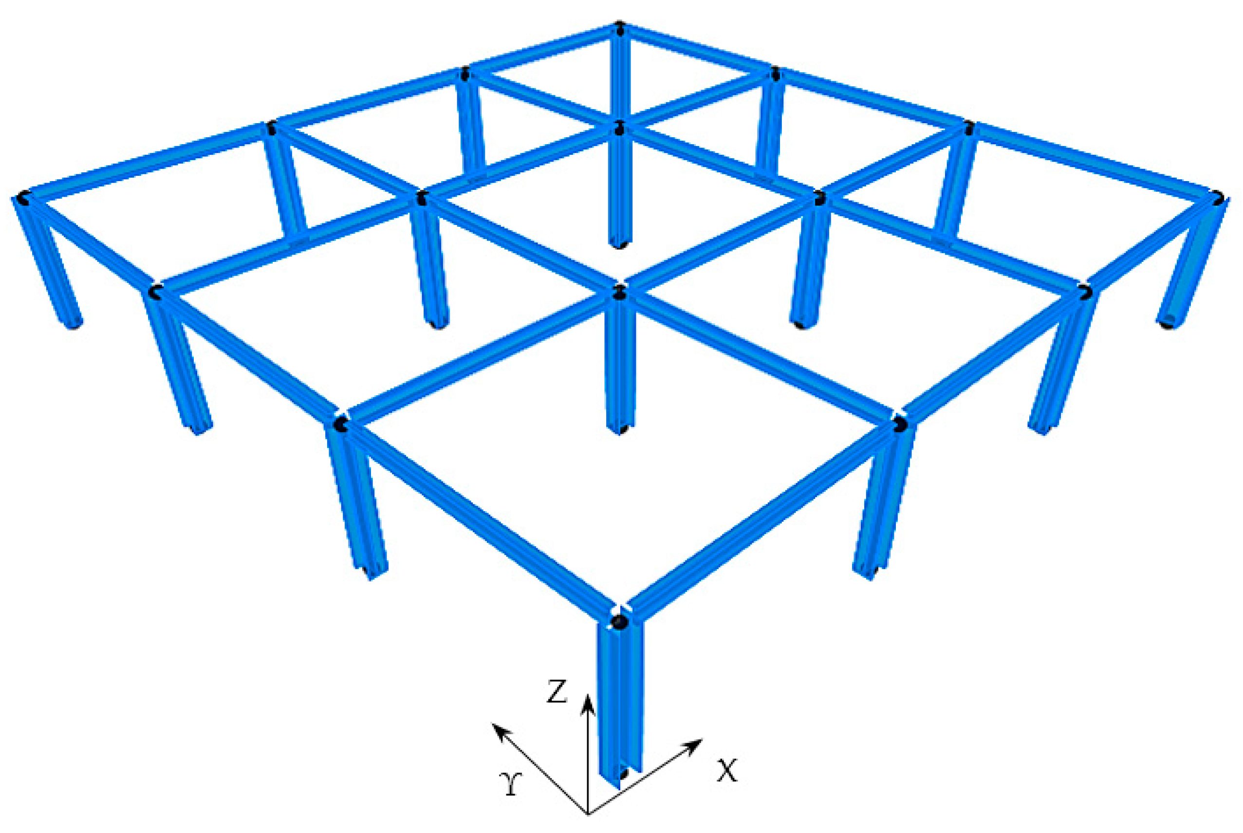
Simple cases of mixed building models are investigated within the present study, aiming to discuss the consequence of deformable soil in comparison to the inflexible base hypothesis. Figure 1 illustrates the construction of the mixed models, with reinforced concrete (r/c) for the lower part and structural steel for the higher part. The first mixed building, referred to as “RC1-ST1”, is composed of a bottom r/c story with an elevation of 4.0 m and a top steel story of 3.0 m (Figure 1a). In Figure 1b, the second mixed building "RC2-ST1" is composed of two lower r/c stories, where the height of the bottom story is 4.0 m, while the height of the second story is 3.0 m, and additionally, there is an upper steel story of 3.0 m height. Figure 1c depicts the third mixed building “RC3-ST1”, which comprises a bottom r/c story of 4.0 m height, two r/c stories of 3.0 m height, and one steel top story of 3.0 m height The fourth mixed building “RC3-ST2” is similar to the previous “RC3-ST1” with an extra steel top story of 3.0 height, as shown in Figure 1d. The last examined mixed building, “RC4-ST2”, has four r/c stories, where the bottom one is 4.0 m high and the remaining r/c stories are 3.0 m high, and two steel stories that are 3.0 m high (Figure 1e). The square symmetric plan of the selected models has dimensions of 15.0 × 15.0 m2 with three equal spans of 5.0 m each with the same dimensions at the X- and Y-axes (Figure 2).
The construction materials are concrete type C20/25 [1] reinforced by steel bars and stirrups of steel type B500c [2] and steel grade S355 for steel elements, which are typical for common domestic buildings [1,3]. Floor slabs, 0.15 m thick, act as a stiff floor diaphragm and are constructed with reinforced concrete for the r/c story/ies, or composite r/c and a steel section for the steel one(s). A uniform static weight of 5.0 kN/m2 plus a live-loading of 2.5 kN/m2 is applied upon the floor slabs as uniform surface loading, and a wall static load of 3.0 kN/m is considered upon edge beams applied as uniform linear loading, according to Eurocode 1 (EC1) [49]. The seismic design assumptions used for these models include a zone ground acceleration of 0.36 g, a “viscous damping ratio” [3] of 5%, a “soil type C” [3], a design spectrum of type 1, a ductility class medium (DCM), and an importance factor equal to 1.0, following “Eurocode 8 (EC8)” [3]. Neglecting the consequence of the “Soil–Structure Interaction (SSI)” [3], the contemporary design guidelines [1,2,3,50] fail to consider this impact on the ordinary construction conception, even though it is considered helpful for building performance. As a result, the current model design and dimensioning relies on the rigid soil hypothesis The behavior factor has maximum allowed values [3] of 3.9 for r/c DCM moment resisting frames (MRFs) and 4.0 for steel ones [3]. The used loadings are combined according to the 30% rule, and a 5% accidental eccentricity is considered in the seismic design following [3]. The horizontal alignment of steel column cross-sections is designed to create a strong outer frame, as shown in Figure 2. According to code provisions [8], “brittle non-structural elements” are considered, and the detailing of the r/c part is performed separately from the one for the steel part, as finally shown in Table 1. The foundation mat is dimensioned considering concrete grade C20/25 reinforced by steel bars Φ18/20 of steel type B500c in both horizontal directions, top and bottom, for all mixed models simplistically, according to current codes [2,3].
Concerning the interconnection of the steel and concrete parts, the subsequent situations are considered, following [6,7,8,9]: (i) a fixed support of the steel columns, i.e., transferring moments in both horizontal axes, named “uniform” in the current work; (ii) a stable interconnection of the steel vertical elements only along a single direction, such as the “minor internal axis” [1,2] of each column section, and an essentially “pinned connection” [6] on the other direction, such as the “major axis” [6] of the steel column section, suggesting that minimal-to-zero moment transfer is performed, named “release” here. The described support distinction is essential considering that in practical real construction, the “drilled-in epoxy type anchor rods” [6] used in the base plate connections of the steel vertical elements are unlikely to be fully anchored into a prior r/c one, meaning that the moment capacity of the base-plate connections may be limited. Moreover, the number and positioning of anchor rods are directly proportional to the size of the r/c column, besides the presence of steel reinforcement and stirrups. By this consideration of the two extreme supporting conditions, we can avoid numerous time-consuming studies of the typical mixed model examining various degrees of freedom for the interconnection of the steel and r/c part. In this way, a consideration of the boundary connection types is introduced in this analysis process, while the detailing and the dimensioning remain the same for reasons of comparison.
The mixed model foundation is considered as a foundation mat connecting the base points of the reinforced concrete columns according to the applicable regulations [1,3,50] for the C and D soil types [3,50]. Considering soils C and D, the foundation mat has horizontal dimensions of 17.0 × 17.0 m2 and a depth of 0.40 m, 0.55 m, 0.80 m, 0.85 m, and 0.85 m, for the corresponding mixed models RC1-ST1, RC2-ST1, RC3-ST1, RC3-ST2, and RC4-ST2. The “shear modulus” [3,50] of soils C and D is calculated considering the “shear wave velocity” [3,50] as 270.0 m/s and 180.0 m/s and the “soil density” [3,50] as 1800 kgr/m3 and 1900 kgr/m3, respectively. Following the guidelines of EC8 [3] on great ground accelerations, the “shear modulus” [3,50] is reduced by 50% to consider possible inelastic deformations.
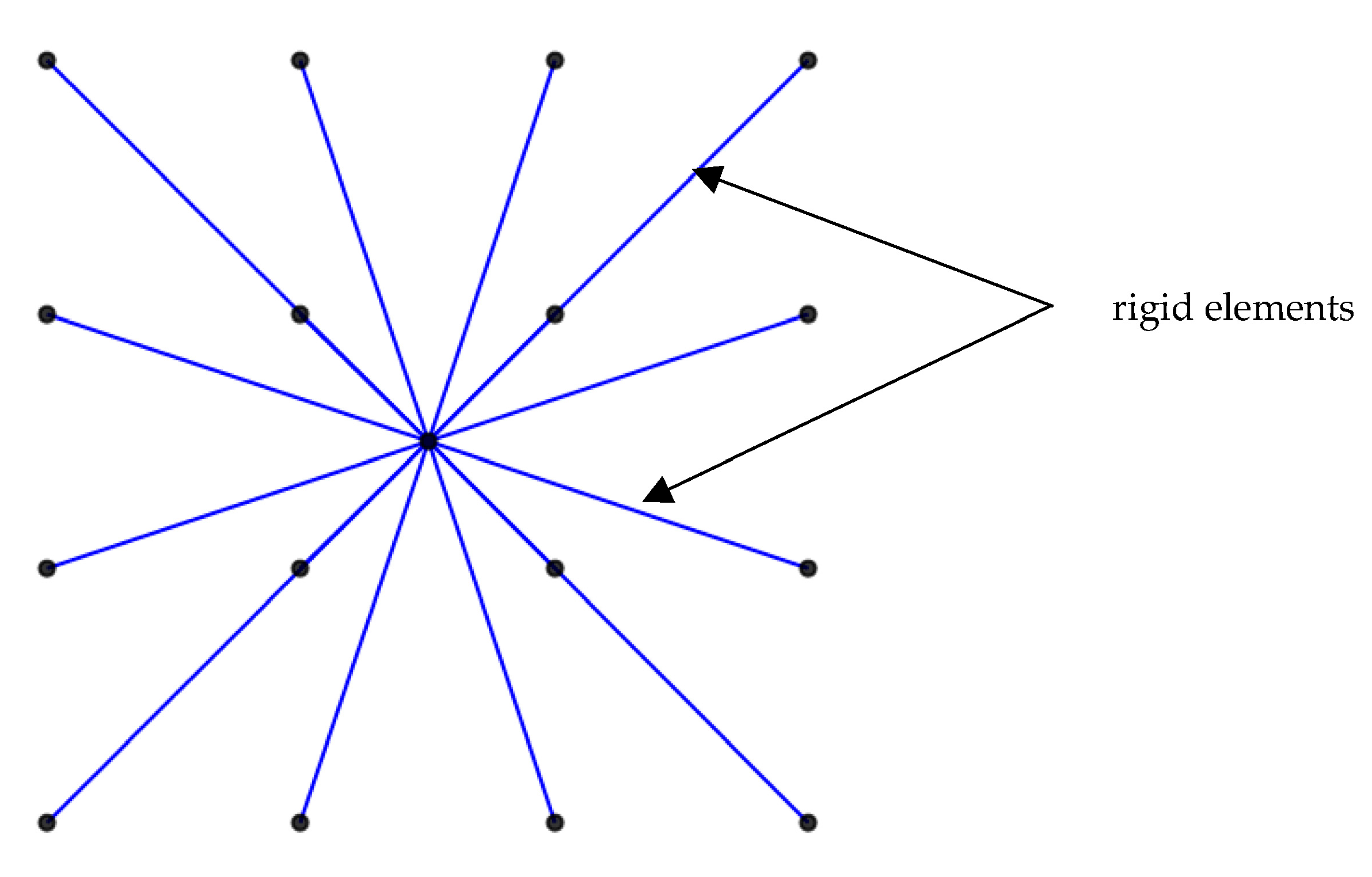
The soil deformability consequence is assessed employing a “discrete” system of “spring–dashpot–mass” [51] elements, with calculated values specified by Mulliken and Karabalis [51] using the relative calculation formulations providing the required mass, stiffness, and damping coefficients, as shown in Table 2 for reading convenience. In the worldwide literature [25,26,27,28,29], more complicated SSI models can be found, which may need time-consuming and complicated calculations and emphasize soil dynamic behavior. Here, attention is drawn to the nonlinear seismic response of the mixed model perspective with the impact of soil deformability in comparison to the rigid soil assumption. By this simple discrete system [51], one “spring–dashpot–mass” element [51] has a position at the foundation mat center and is joined with bases of the vertical elements via horizontal rigid elements (Figure 3).
The analysis model is composed of linear frame elements for beams and columns, supporting the slabs, which are simulated by shell finite elements, as all supplied by SAP2000 software (version 22.2.0) [52]. At the base of the columns, a fixed support is placed for the rigid soil assumption. Otherwise, for SSI consideration, the bases of the columns are connected by rigid elements (as in Figure 3) to the central spring-dashpot-mass element represented by a link element in [52], incorporating all necessary parameters. In this way, three boundary-supporting conditions are considered for the structure support for each mixed model, i.e., rigid soil and deformable soil of types C and D. In addition, the interconnection of the steel part on the r/c part is considered as either a simple connection of frame elements for the aforementioned “uniform” connection, either as a “release” connection indicating the placement of appropriate releases at the interconnection nodes in the analysis model by [52]. The used software [52] is chosen because of the great variety of elements, links, and hinge properties, which are all available for the creative construction of the analysis model according to the design engineering assumptions and requirements.
Modal analysis is performed for the mixed frames considering at first the “uniform” interconnection of the steel and reinforced concrete parts, then for the “release” connection by SAP2000 software [52], accounting for the inflexible soil, and then for the SSI regarding the C and D soil grades. The fundamental (first) eigenperiod of the mixed models for the two considered connection types and the examined supporting cases is listed in Table 3. The first modal period for the “release” connection appears slightly greater than the respective one for the “uniform” connection for the same model for all considered ground supports, as observed in Table 3. Table 3 indicates that considering deformable soil tends to increase the first modal period, as opposed to the rigid soil, while slightly greater values of the first modal period are observed for soil type D than C, respectively.
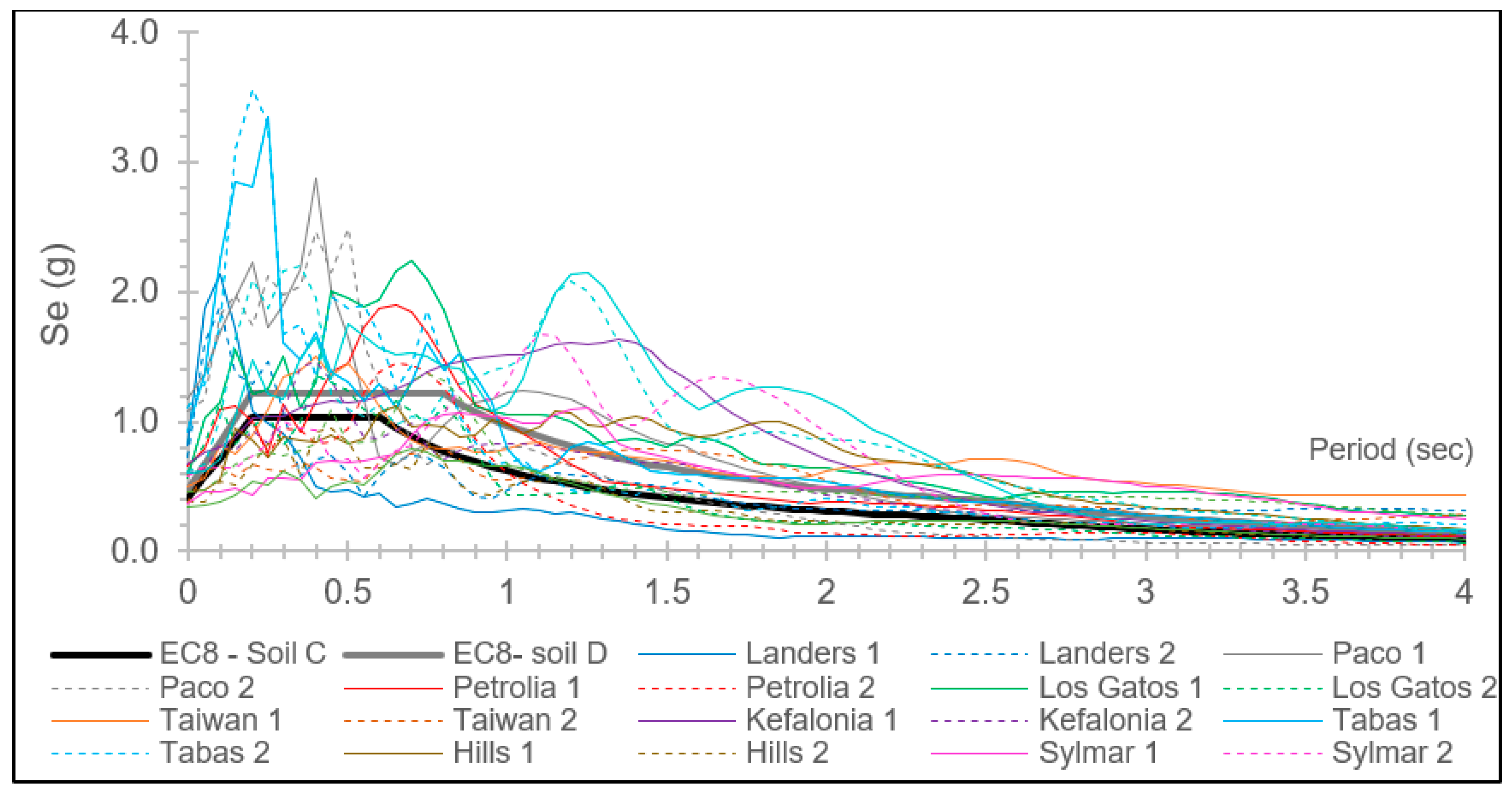
The mixed frames are subjected to strong near-fault earthquakes by nonlinear time history (NLTH) analysis, as performed by [52]. As listed in Table 4, the considered recorded excitations are downloaded from the records of [53]. The basic earthquake characteristics are given in Table 4, such as the name, the location, the earthquake year, the recording station, the plot name, the duration, the moment magnitude (Mw), and the peak ground acceleration (PGA) in the two horizontal directions. The considered earthquake spectra are calculated with the aid of [54] and plotted in Figure 4, which shows the plotted design spectra of [3] for a zone ground acceleration of 0.36 g, type 1, and soil type C, and, respectively, for soil type D [3]. The earthquake spectra are observed to vary within and higher than the value’s range of the design spectra [3], so these strong near-fault seismic records are appropriate for this investigation of the response of the mixed models under intense ground motions evaluating the SSI in comparison to the rigid soil assumption.
The angle of the seismic input direction was determined to strongly affect the structural response in various studies, as indicatively shown in [37,38,40,41,42,45,46,47]. Because of the symmetrical shape of the plan of the considered mixed models, herein, the incidence angles in the NLTH analysis are selected as 0° and 90° in the X-Y plane following the global coordinates system shown in Figure 1.
To conduct the time-expensive NLTH analysis, the necessary “damping ratio” [3] value used in the NLTH model analysis is calculated following the approach of Sivandi-Pour et al. [17,18], where the arithmetical resulting values are as follows: 4.57% regarding the RC1-ST1 model, 4.33% for the RC2-ST1 model, 3.63% for the RC3-ST1 model, 2.31% for the RC3-ST2 model, and 2.14% for the RC4-ST2 model. In the used software [52], the analysis model consists of frame elements where their possible inelastic performance is simulated by point plastic hinges assumed at their ends. In this work, a simple nonlinear mechanical model of concrete members with changeable loading is incorporated into the analysis model by the authors of [52] by applying point hinges at element ends. More detailed and complex mechanical models may be found in the literature; however, here, a simple one is selected fdue to simplicity reasons, conforming to current standards, without needlessly extending beyond the scope of this work, which is the influence of the SSI on the seismic response of mixed buildings. These nonlinear r/c point hinges are associated with elastoplastic material sectional properties [55], such as the decrease in strength and the post-yield hardening ratio of 5%. The backbone moment–rotation curve is expressed following standard ASCE 41-17 [55]. The cracking deterioration of stiffness is also considered for r/c elements, which is assumed as 0.50 following Eurocode 2 (EC2) [1] and EC8 [3]. The Takeda hysteresis model [1,52] provides the inclined stiffness and strength into the analysis model, while a possible “shear failure of r/c sections” [1,3,37,38] is reviewed based on [3]. Correspondingly, the application of nonlinear point hinges at steel element ends [55] considers a strain hardening of 2%, the hinge rotation limits for the seismic performance levels [55], etc. Thus, the considered simple approximation of the nonlinearities for structural r/c or steel elements, while conforming to effective standards [1,2,3,4,55], stays within the interest of this study, which is the soil deformability consequences regarding the dynamic response of mixed structures without interfering with sophisticated material mechanical models, which may be found in various research articles.
The total number of dynamic time-domain analyses conducted for each mixed model, as shown in Figure 1, is 132, which means 11 (earthquake excitations) times 2 (for the two incidence angles) times 2 (corresponding to the “uniform” or “release” interconnection of the steel and r/c parts) times 3 (for the supporting assumptions of the rigid soil, soil C and soil D). Thus, in the following section, the selected results of 660 NLTH analyses are presented and discussed qualitatively.

3. Results and Discussion

The calculated findings of the NLTH analyses of the mixed models are presented in the current section and discussed. Dimensionless variables are selected for the presentation and objective evaluation of the analysis plots, focusing on the investigation of the alteration of the seismic behavior of the mixed models resulting from the SSI in comparison to the rigid soil assumption.
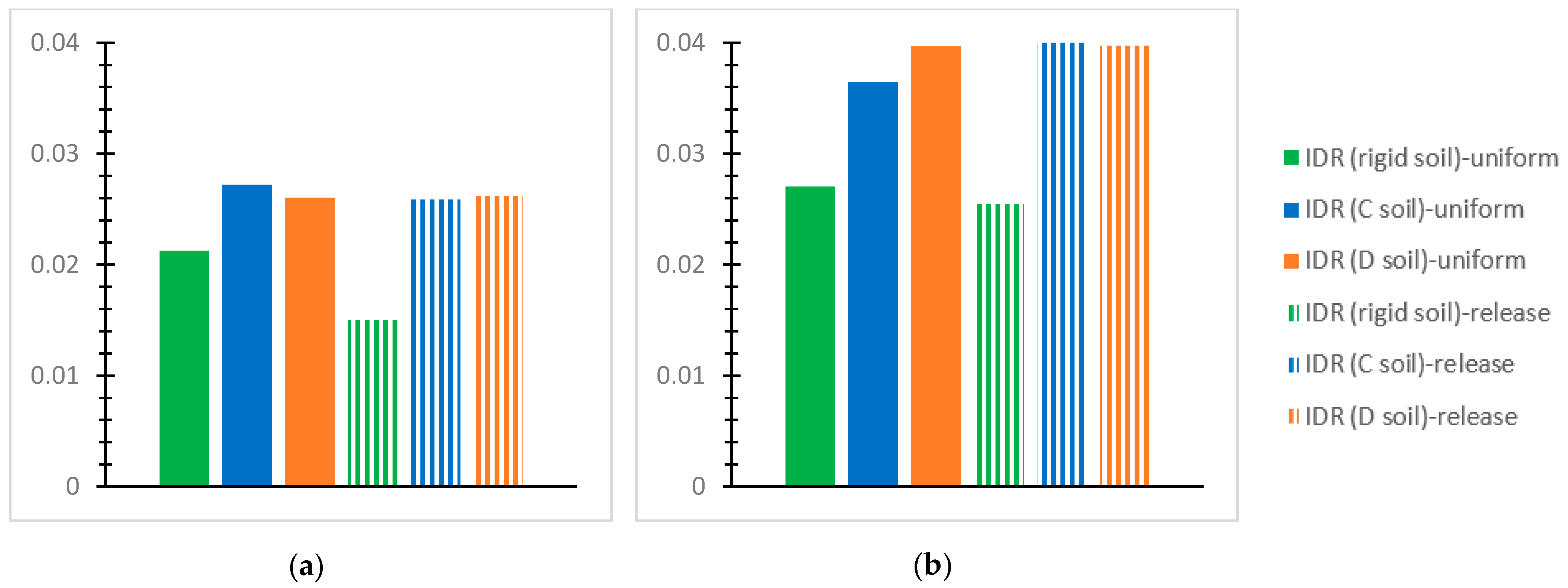
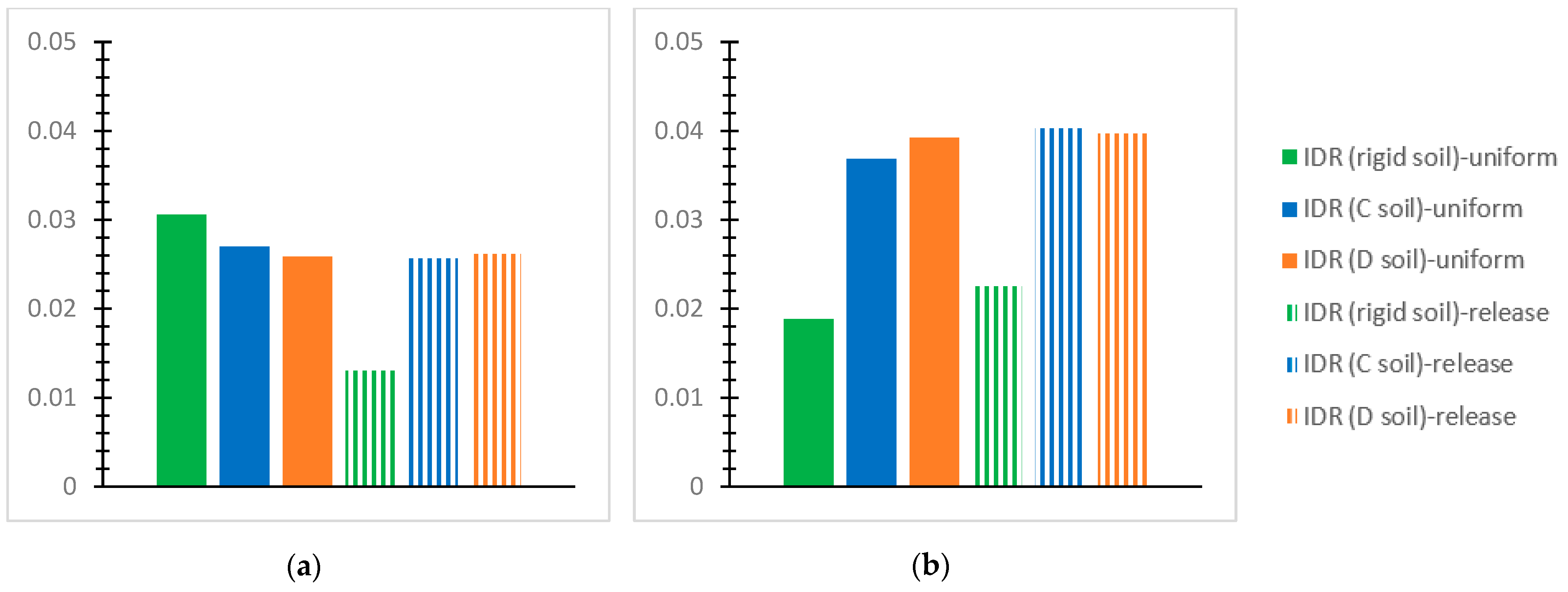
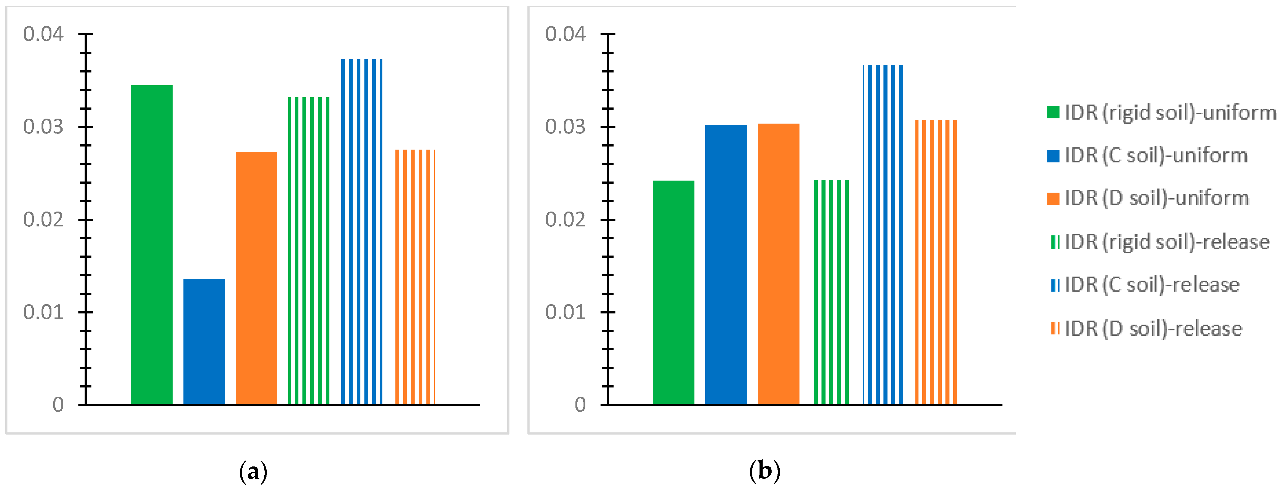
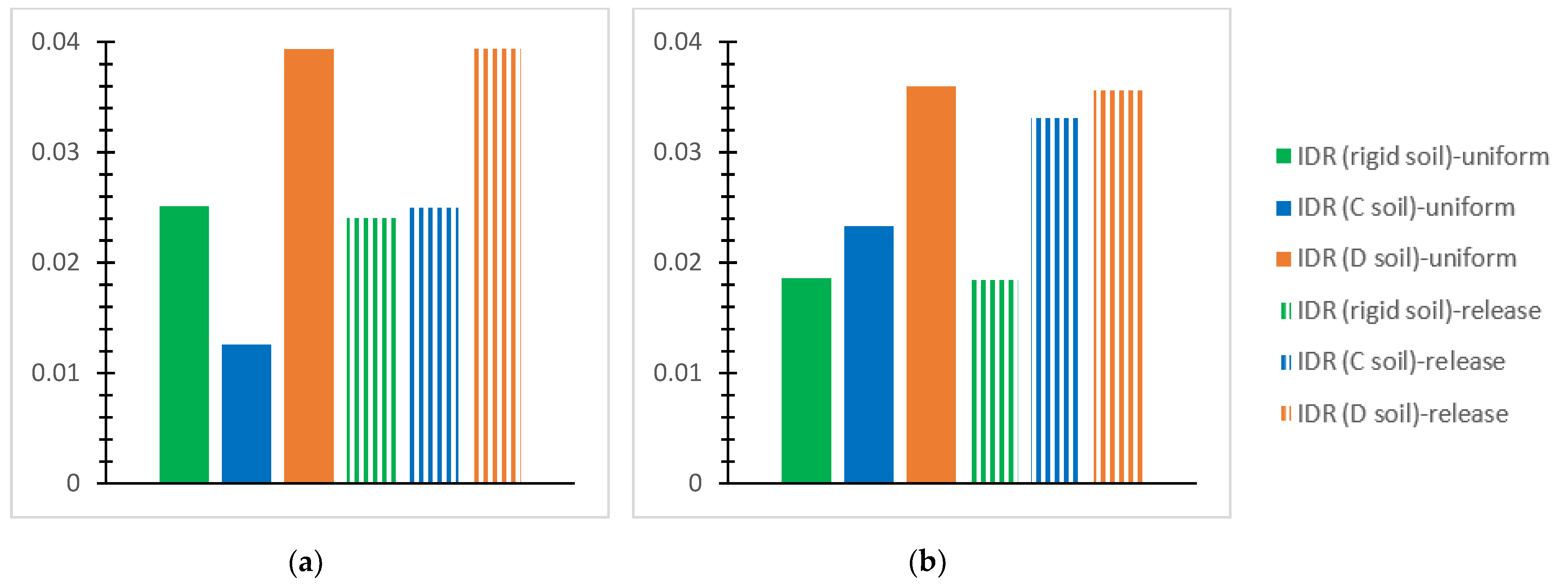
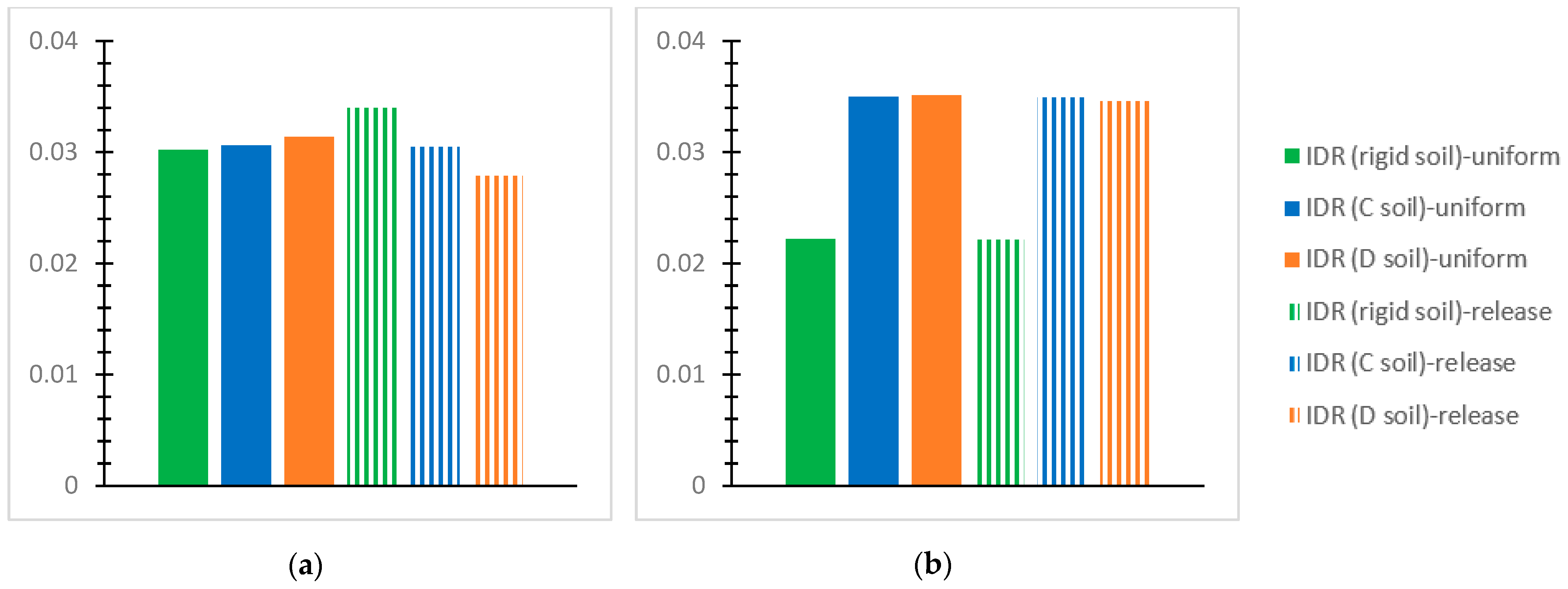
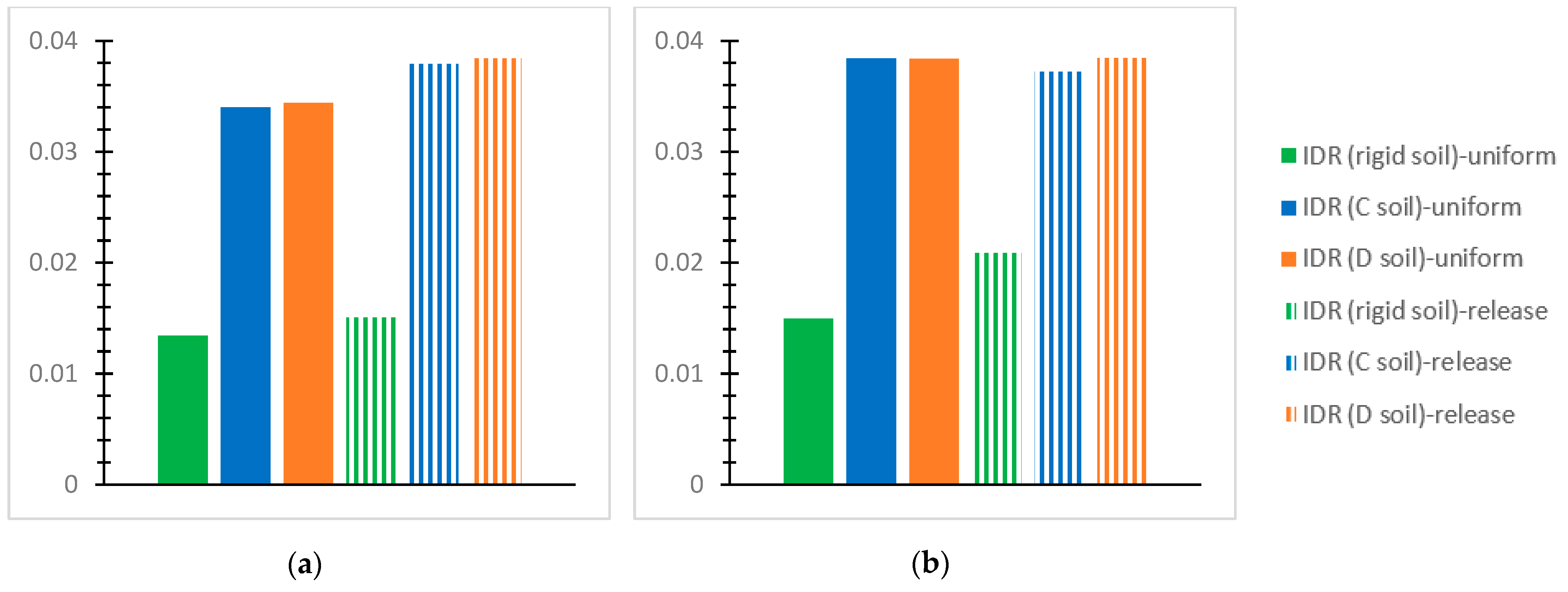
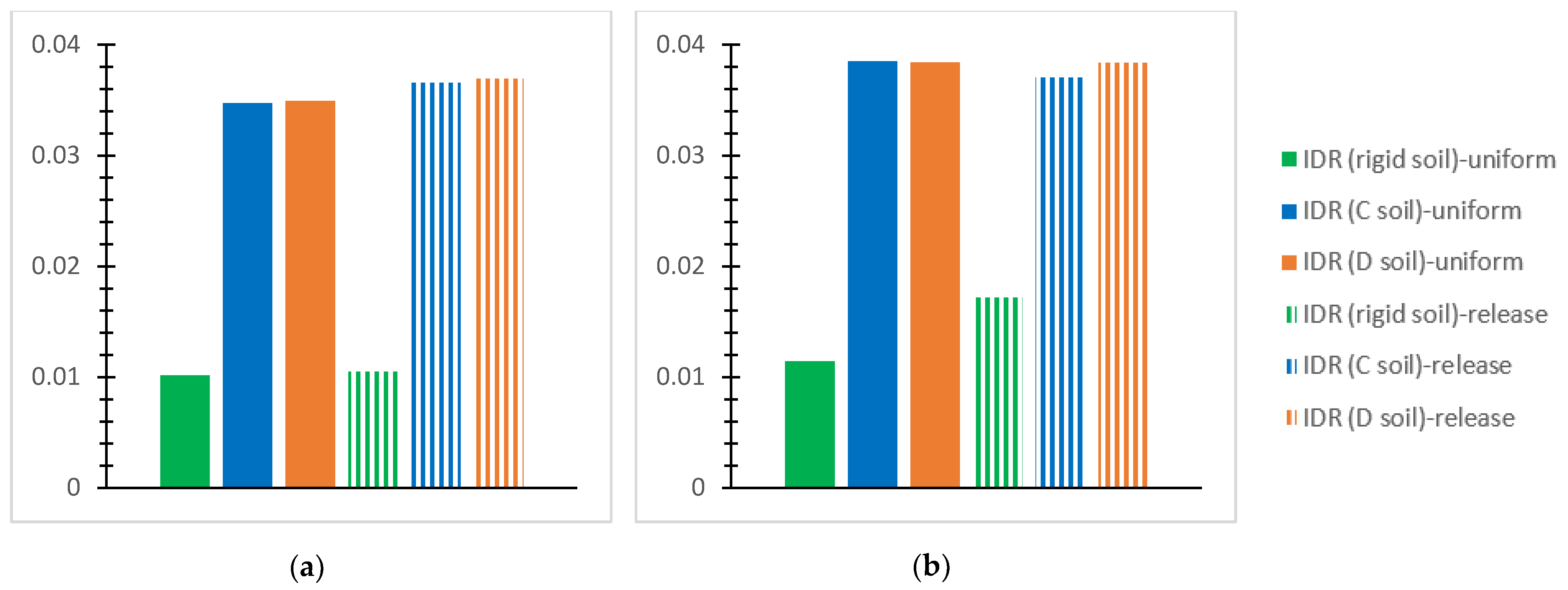
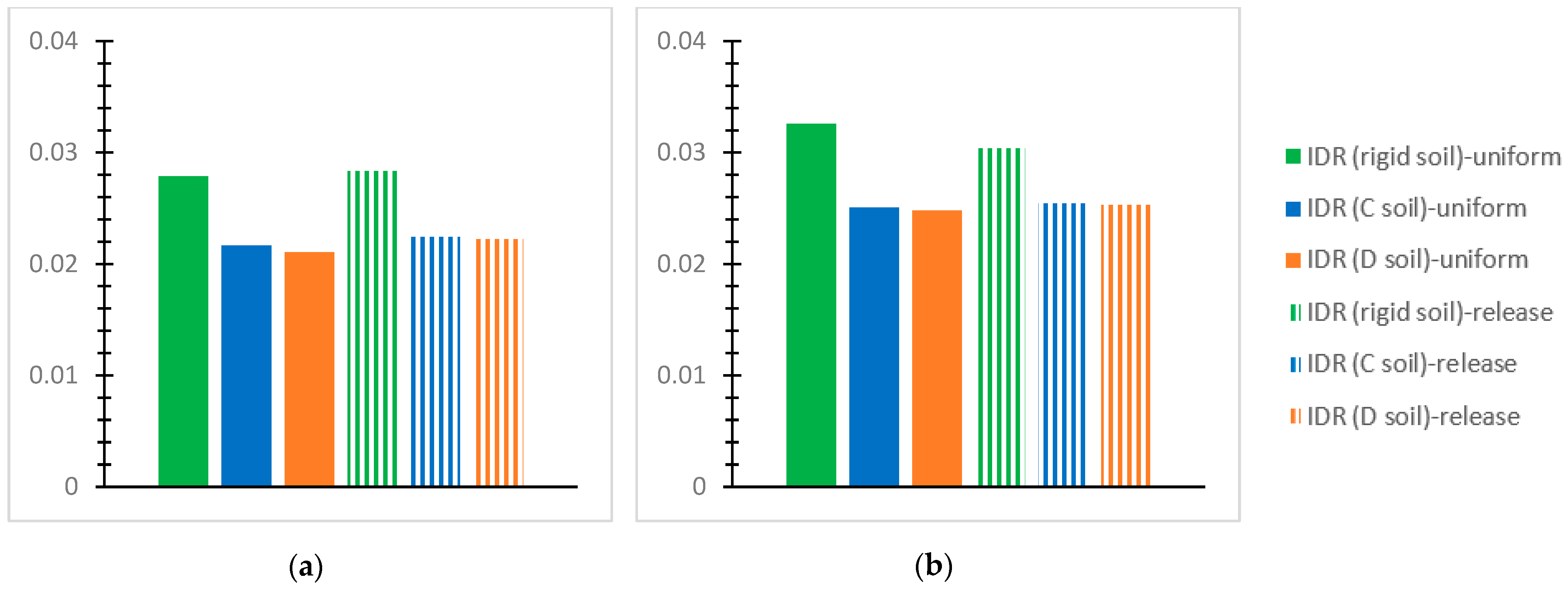
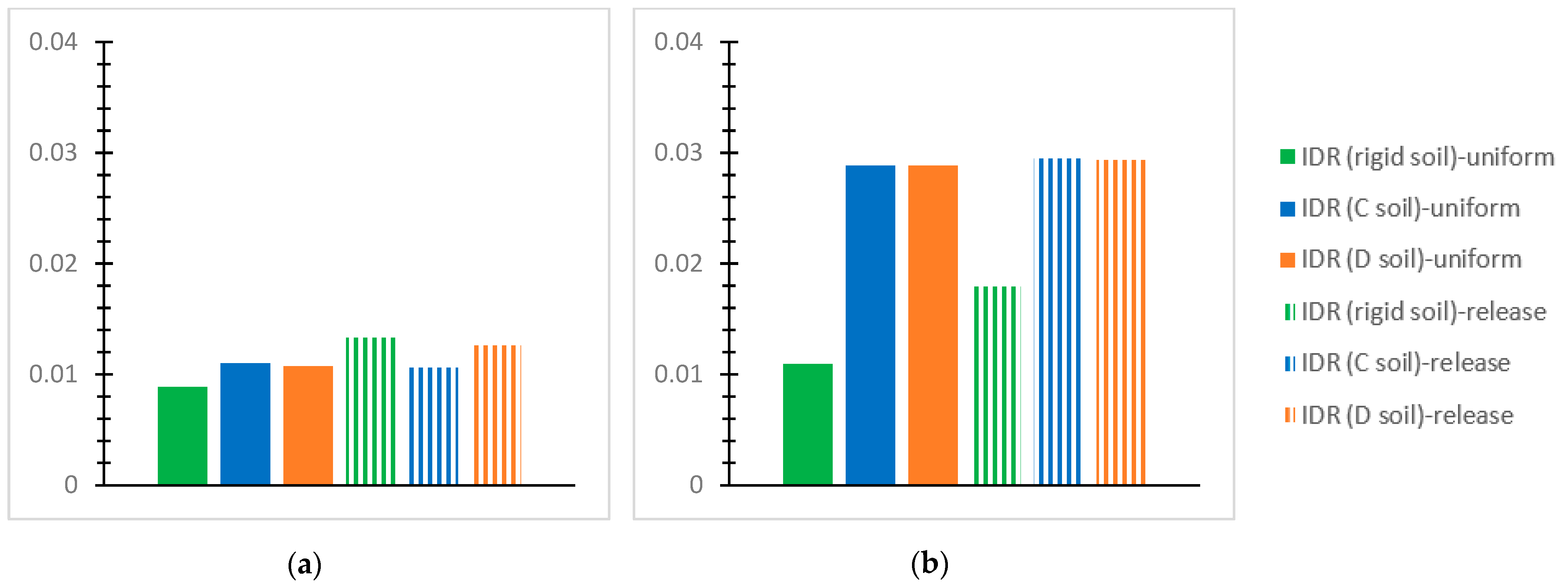
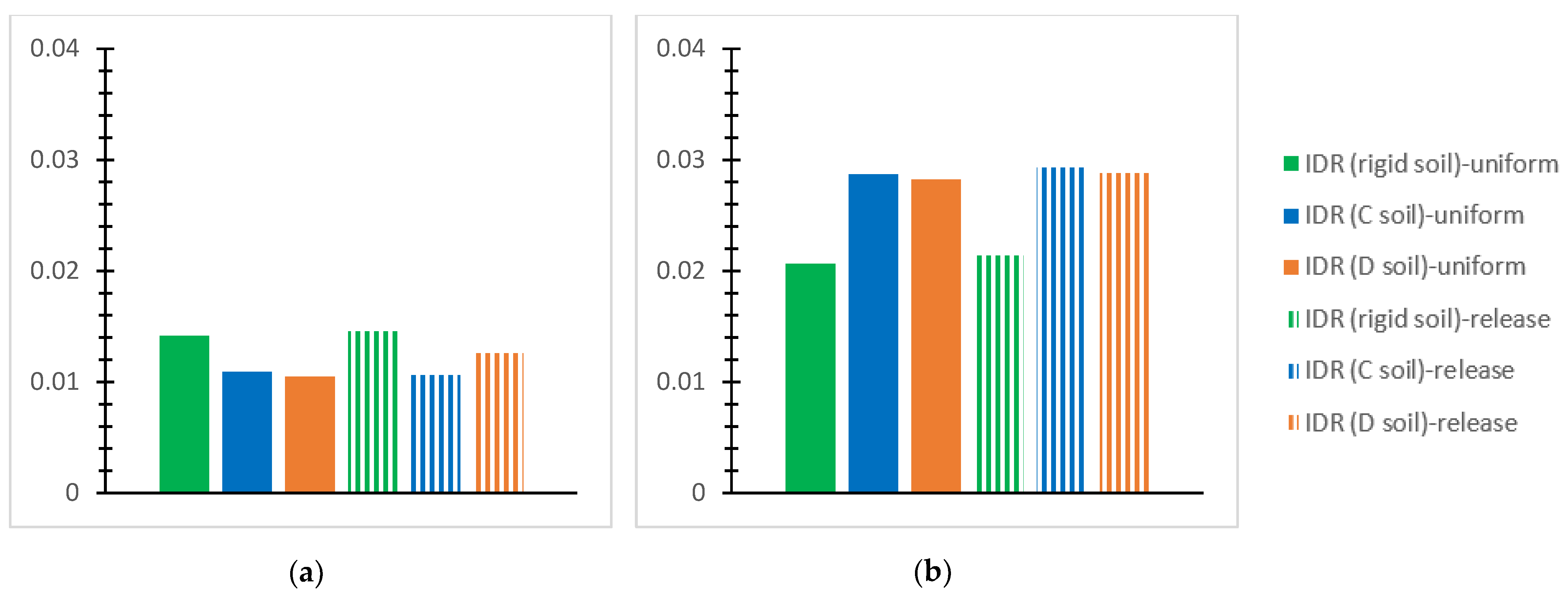
  • For the inflexible soil assumption and the SSI via the C and D soil grades for the performed NLTH analyses of each mixed building at each story, the greatest value of the “interstory drift ratio (IDR)” [56] is plotted for the two interconnection forms with the notations “uniform” or “release”, as mentioned previously. The IDR values at the horizontal global axes, X and Y, are discussed concerning the effective limits for concrete frames [56] as follows: 1% in terms of the “Immediate Occupancy (IO) performance level” [56]; 2% in terms of the “Life Safety” (LS) performance level” [56]; and 4% in terms of the “Collapse Prevention (CP)” [56] level. The respective limit “IDR” [56] values for steel frames are 0.7% regarding the “IO” level [56], 2.5% referring to the “LS” level [56], and 5% regarding the “CP” level [56].
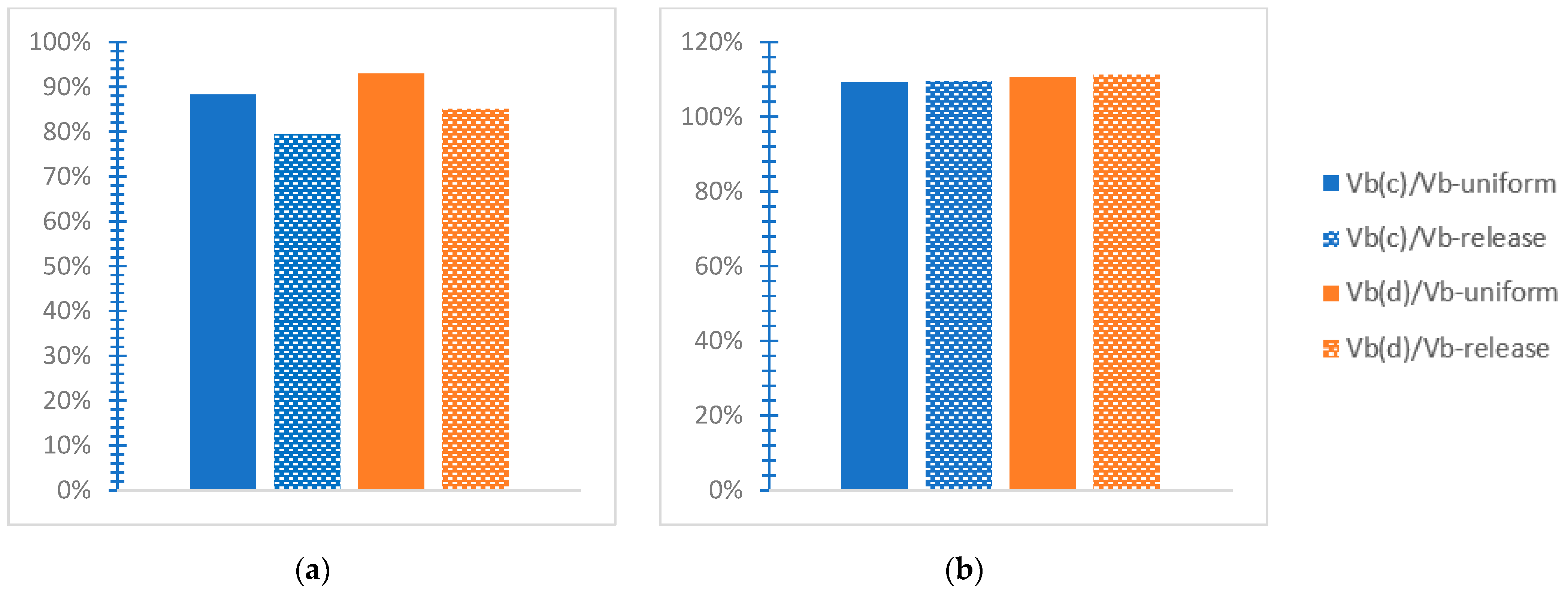
  • “Vb(c)/Vb” refers to a proportion of the “greatest absolute value of the base shear” [38] for the SSI by soil C “Vb(c)” to the respective value for the inflexible soil “Vb”, with the notation “uniform” or “release”, as previously stated. Considering the SSI via soil D, this ratio is represented as “Vb(d)/Vb” along the two horizontal global axes.
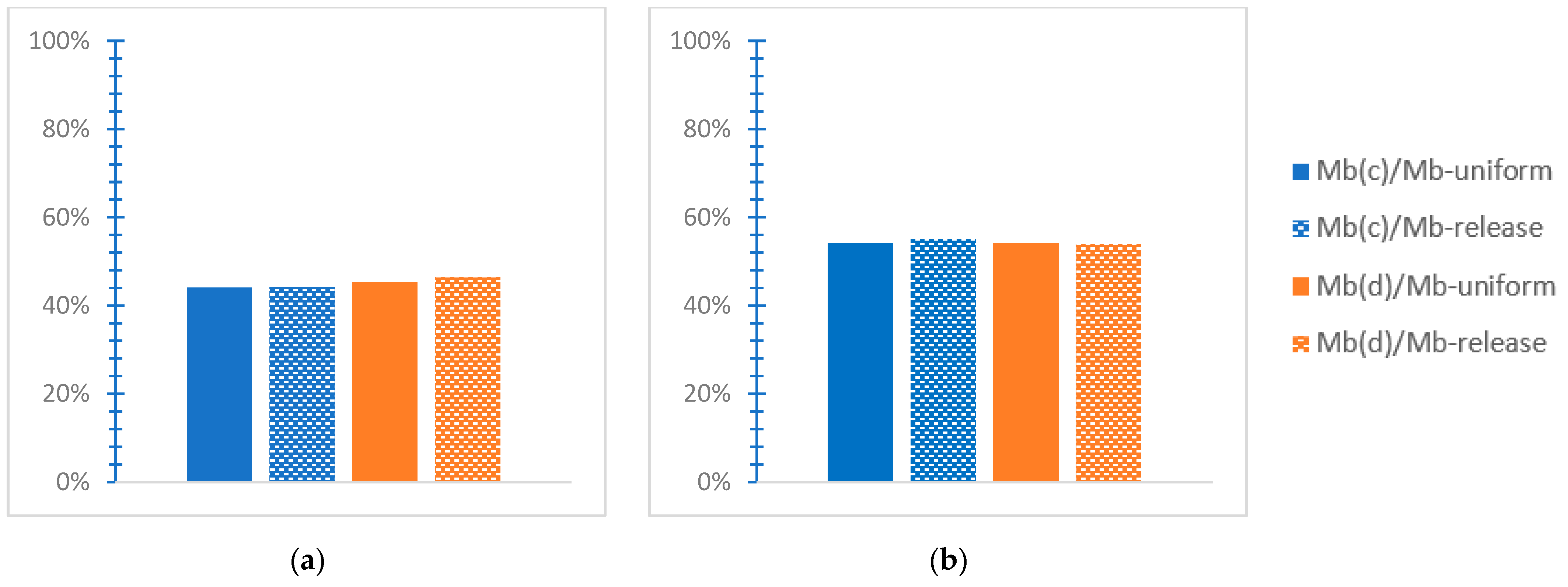
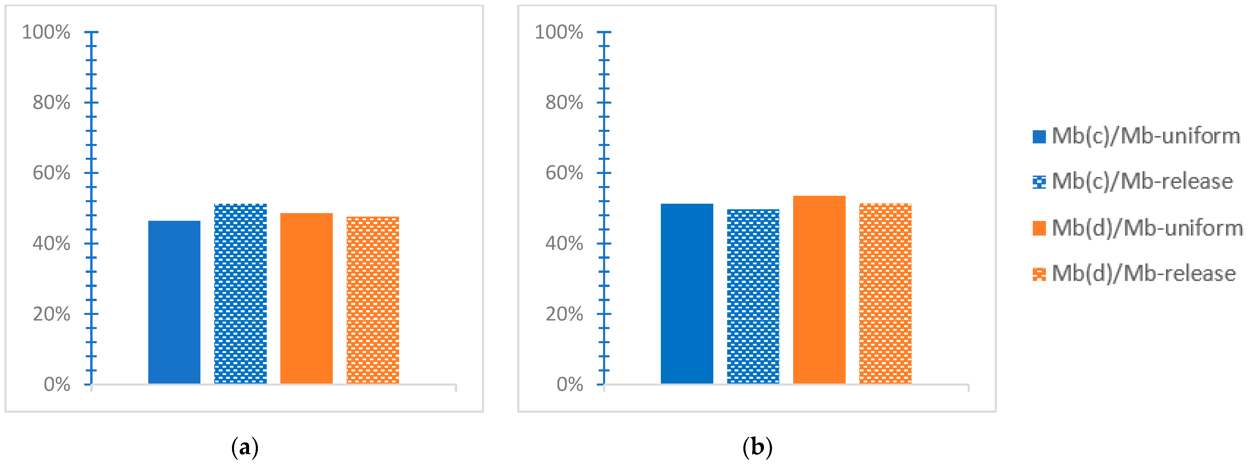
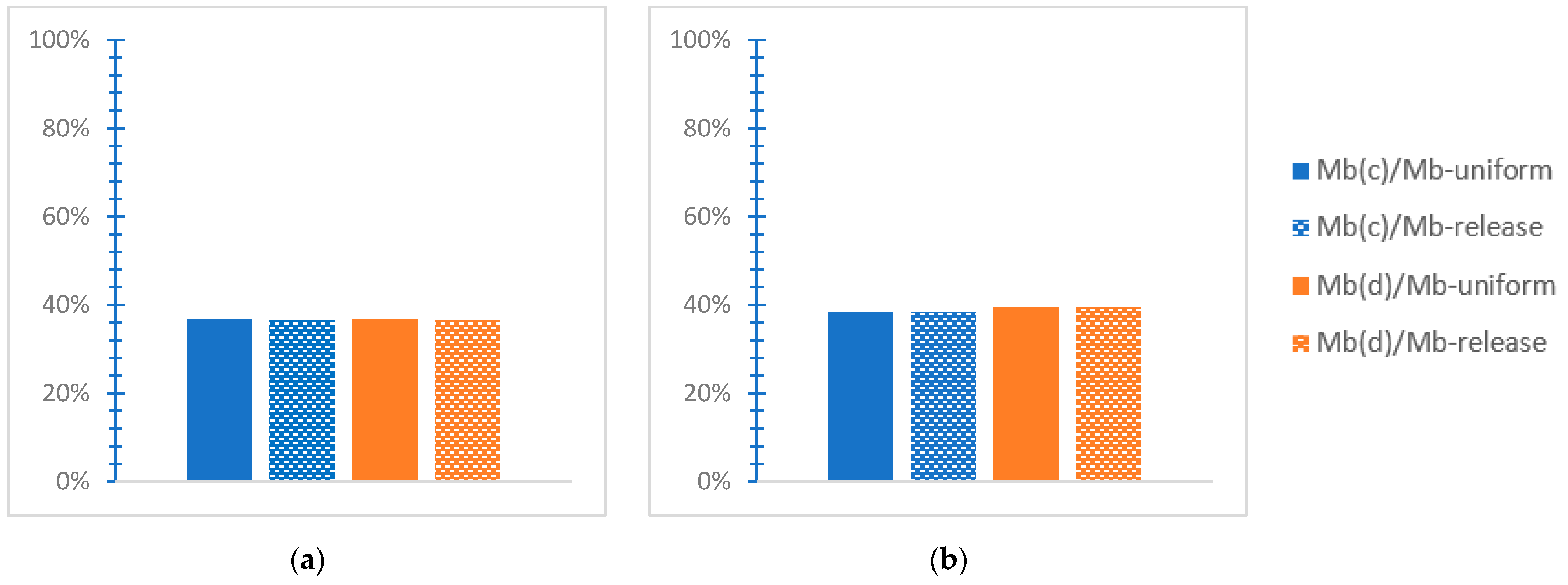
  • “Mb(c)/Mb” is an analogous ratio considering the base moment for soil C, and Mb(d)/Mb refers to soil D.
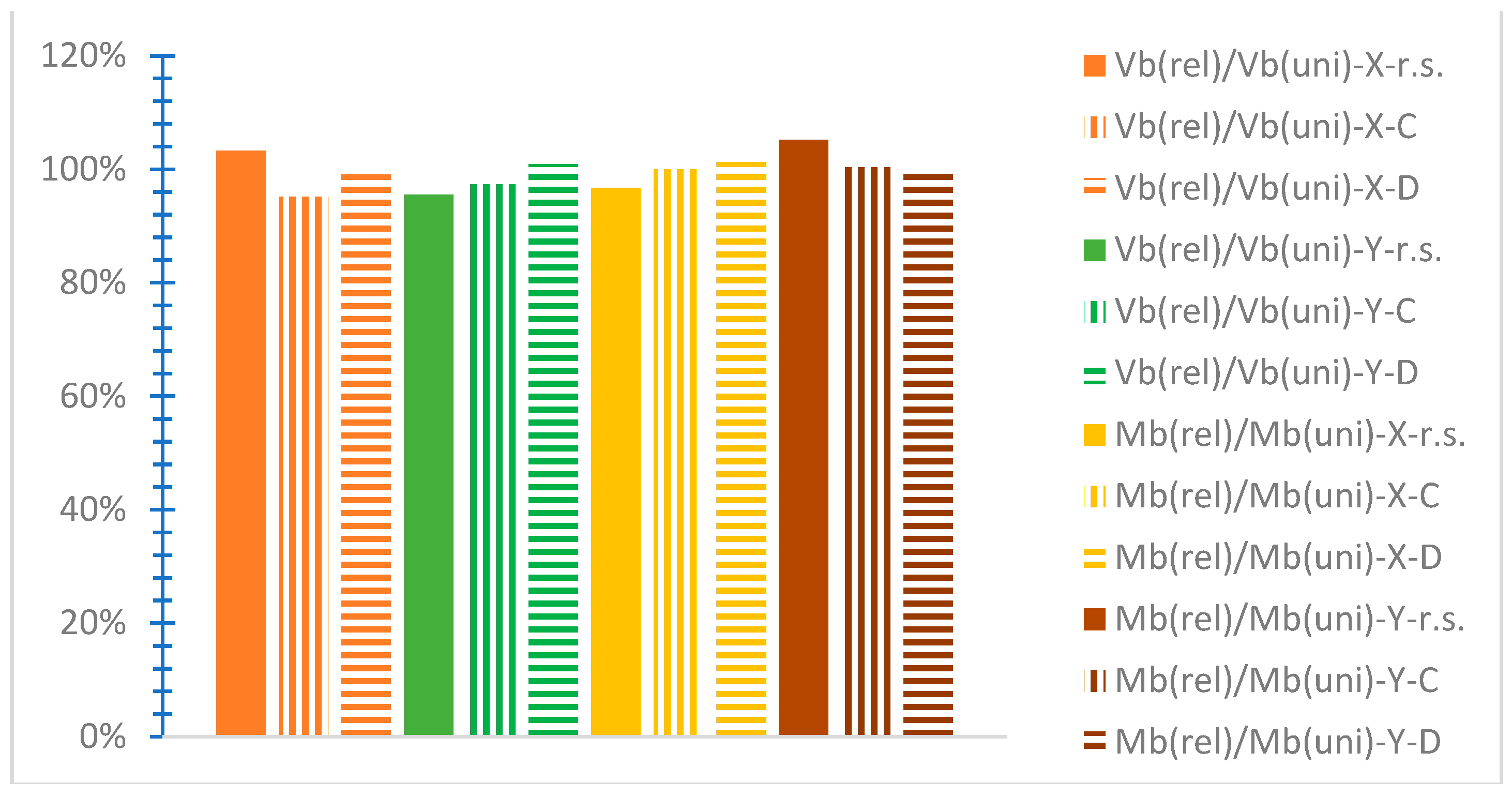
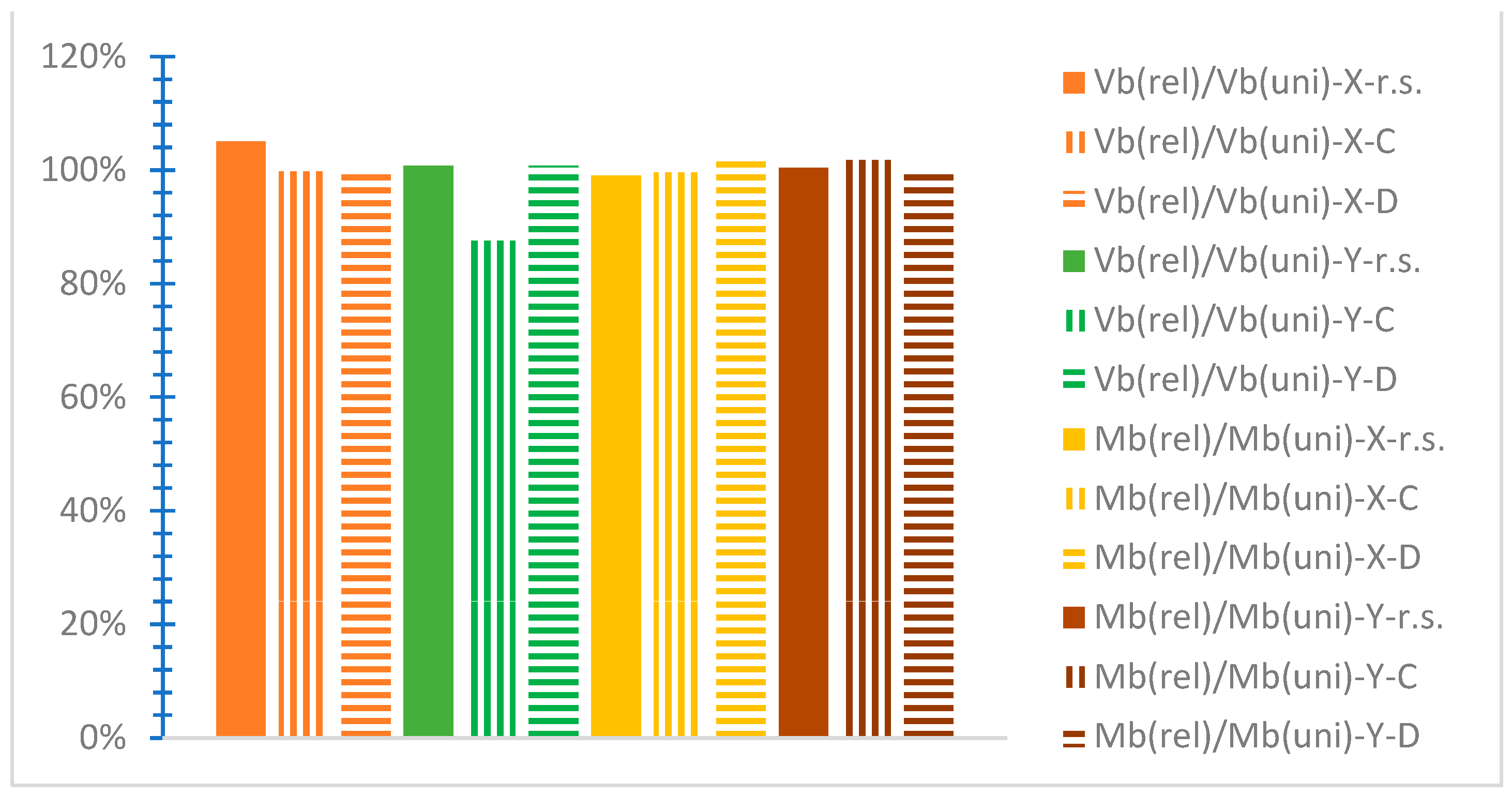
  • “Vb(rel)/Vb(uni)” stands for the proportion of the greatest “absolute base shear value” [38] of the NLTH analyses for each mixed building for the “release” connection type divided by the corresponding value for the “uniform” connection type at both horizontal global axes, considering either the rigid soil “r.s.” or the SSI by the C soil type “C”, or the SSI via the D soil type “D”. Respectively, the “Mb(rel)/Mb(uni)” ratio refers to base moment ratio, with the same notations, “r.s.”, “C”, or “D”.
Because of space limitations, selected response diagrams are displayed, focusing mainly on the effect of the SSI comparatively to the rigid soil assumption, distinguished in subsections for each mixed model.

3.1. Comments on the Two-Story Mixed Model (RC1-ST1)

Concerning the RC1-ST1 building, at the first story (Figure 5a), the maximum IDR along the X-axis value is 1.8%, within the LS level [56] for rigid soil and the “uniform” connection, and 2.34% is the maximum for the “release” interconnection. Considering the SSI for soil C, the IDR-X shows the greatest value of 2.9% for the uniform connection and 2.7% for the release connection, while for soil D, the IDR-X has the highest value of 2.7~3% for these connection types (Figure 5a). On the Y-axis, (Figure 5b), the highest IDR for the rigid soil is observed as 2.3% for the uniform connection and 3% for the release connection. Considering soil C, the maximum IDR-Y is 4%, i.e., the “CP” restriction [56], considering both connection types (Figure 5b). For soil D, the maximum IDR is almost 4% for the uniform connection and 3.9% for the release connection (Figure 5b).
At the second story of the RC1-ST1 building, the maximum IDR-X for the rigid soil is observed in Figure 6a as 0.9% for the uniform and 1.9% for the release support in the “LS” level [56]. For soil C, the IDR-X shows values up to 2.1% for the uniform connection and 2.3% for the release connection, while for soil D, the IDR-X is observed up to 2.2% for the uniform and 2.1% for the release connection types (Figure 6a). On the Y global axis, the IDR rises to 4% for soil C and the uniform interconnection and shows a lower value of 1.9% for the uniform connection considering the rigid soil assumption (Figure 6b).
In the IDR plots, comparisons are shown for the NLTH analyses with maximum values within the acceptable limits of [56] while omitting the analysis cases with IDR values much greater than these limits, which indicates building failure. For the rigid soil assumption, all seismic analyses had maximum IDRs within the permittable limits for both connection types. For soil type C, results are shown considering the uniform connection type for the excitations of Landers with 0° and 90°, San Fernando with 0°, and Imperial Valley with 0° and, when considering the release connection, the excitations of Landers with 90°, San Fernando with 0°, Cape Mendocino with 90°, and Imperial Valley with 0°. For soil type D, considering the uniform interconnection, the results include the excitations of Landers with 0° and 90°, San Fernando with 0°, Cape Mendocino with 90°, and Imperial Valley with 0°; correspondingly, for the release connection, the results include the excitations of Landers with 0°, San Fernando with 0°, and Imperial Valley with 0°.
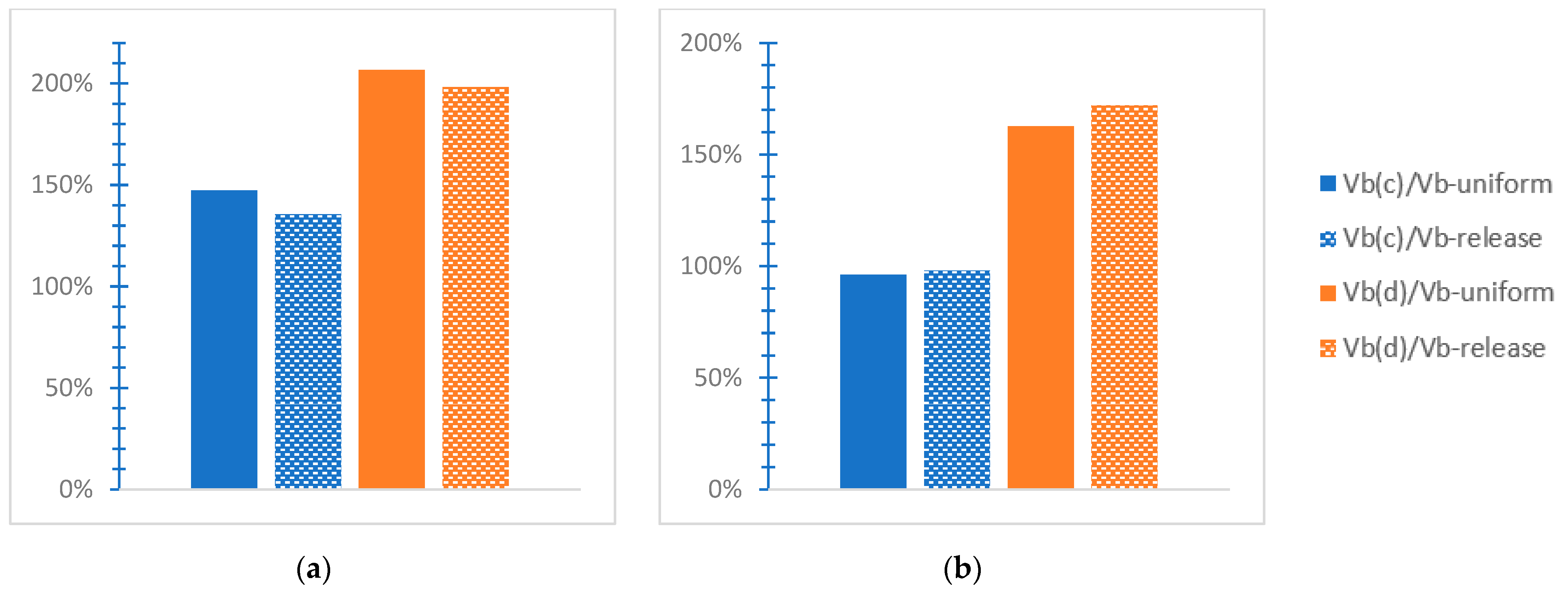
At the RC1-ST1 building, as shown in Figure 7a, the Vb(d)/Vb ratio along the X-axis presents the highest value of 207% regarding soil D and the uniform connection form, and Vb(d)/Vb has a smaller value of 136% for the C soil type and the release connection. Respectively, as shown in Figure 7b concerning the Y-axis, the Vb(d)/Vb ratio has a maximum value of 172% for the release connection and a respective minimum value of 96% for the uniform connection for soil type C.
The base moment ratio along the X-axis (Figure 8a) varies in the range of 62~67% for both soil types and both interconnections. Respectively, along the Y-axis (Figure 8b), the Mb(c)/Mb has a maximum value of 82% for the uniform connection, while a minimum value of this ratio of 74% is observed for soil D and the release connection. The effect of the SSI is presented as harmful because of the base shear ratio (Figure 7) and beneficial because of the base moment ratio (Figure 8), as opposed to the inflexible soil.
A comparison of the base shear and moment ratios for the release to the uniform connection is shown in Figure 9 for each considered ground support, i.e., the rigid soil assumption (r.s.) and the SSI via soil types C and D. The Vb(rel)/Vb(uni) ratio varies in the value range of 95%~103% with the highest value for the rigid soil on the X-axis. The Mb(rel)/Mb(uni) ratio has a value range of 97%~105% with greater values for the inflexible base on the Y-axis. The Vb(rel)/Vb(uni) and Mb(rel)/Mb(uni) ratios tend to have greater values concerning the inflexible base than soils C and D in the cases of a base shear ratio on the X-axis and a base moment ratio on the Y-axis, while in the rest cases, smaller values are observed in Figure 9 for the rigid soil assumption than for soil types C and D.

3.2. Comments on the Three-Story Mixed Model (RC2-ST1)

In Figure 10a, regarding the RC2-ST1 building, at the first story, the maximum IDR-X is observed as 3.4% for soil C and the release connection and the minimum value is 2.2% for the rigid soil and the release connection. In Figure 10b, the IDR-Y presents a maximum value of 4%, i.e., the limit of the “CP” level [56], for soil C and the uniform connection and a minimum value of 2.9% for the stiff soil and the uniform connection.
At the second story of the RC2-ST building, in Figure 11a, the IDR-X presents a range in the “CP performance level” [56], with a maximum value of 2.7% for soil C and the uniform interconnection and a minimum of 1.5% for the rigid soil and the release connection. The IDR-Y has a minimum value of 2.5% for the rigid soil and the release connection and a maximum of 4% for soil C and the release connection (Figure 11b).
At the third story of this building, the plot of the IDR-X (Figure 12a) presents similarity to the plot for the second story, with a minimum value of 1.3% for the rigid soil and the release connection and a greater value of 3.1% for the rigid soil and the uniform connection. Respectively, the IDR-Y plot presents the smallest value of 1.9% for the rigid soil and the uniform connection and a maximum value of 4% for soil C and the release connection (Figure 12b). A similar general shape in the IDR plots is observed on each global horizontal axis, tending to slightly smaller values for higher stories, as in Figure 10, Figure 11 and Figure 12.
In the analysis of the RC2-ST1 building supported on rigid soil, the results for the excitation of Loma Prieta with an angle of 90° for the uniform connection type are excluded because of extreme drift ratios with numerical values significantly greater than the standard limits [56]. For similar reasons, the IDR plots include the response results considering the C soil type, for the uniform connection type, the excitations of Landers 90°, San Fernando 0°, and Petrolia 0°, and for the release connection type, the excitations of Landers with angles 0° and 90°, and Petrolia with angle 90°. For soil type D, the IDR response results are shown for both connection types for the earthquakes of Landers with angles of 0° and 90° Petrolia with an angle of 90°.
Concerning the RC2-ST1 building, in Figure 13a, the base shear ratio on the X-axis presents the greatest value of 168% for the uniform connection and soil type D and the minimum value of 125% for the release connection and soil type C. In Figure 13b, the base shear ratio along the Y-axis has almost the same plot values as 132% for either connection type considering soil type D and a smaller value of 108% for soil type C and the release connection. The plots of the base shear ratio in Figure 13 show a detrimental SSI impact on the seismic behavior of the mixed models, in contrast to the inflexible soil assumption.
The base moment ratio along the X-axis (Figure 14a) has a similar value range of 44~46% for both connection types and both soil types, with slightly higher values for the release connection and soil D. The base moment ratio along the Y-axis varies around 54~55% for both connection and soil types (Figure 14b). The plots in Figure 14 indicate a beneficial SSI effect on the structural response as opposed to inflexible soil.
The Vb(rel)/Vb(uni) percentage tends to slightly greater values regarding the inflexible soil by 5~13% as compared to soils C and D. The Mb(rel)/Mb(uni) ratio displays smaller values for the inflexible soil by 2% than for soils C and D (Figure 15), indicating a negative consequence of soil deformability, considering the release connection type versus the uniform connection, in contrast to the inflexible soil assumption, given this dimensionless parameter.

3.3. Comments on the Four-Story Mixed Model (RC3-ST1)

At the first story of the RC3-ST1 building, the IDR-X presents, in Figure 16a, a range of values up to 0.037 for the C soil type and the release interconnection, while a minimum of 0.014 is observed for the C soil type and the uniform connection type. Respectively, on the Y-axis, the IDR shows an increased value of 0.037 for the C soil type and the release connection, and a smaller value of 0.024 for rigid soil and the uniform connection (Figure 16b).
At the second story, the IDR-X has the top value of 0.039 for the D soil type for both connection types, which is almost in the “CP performance level” [56], and the smallest value of 0.013 for the C soil type and the uniform connection (Figure 17a). The IDR-Y has increased values up to 0.036 for the D soil type and both connections and a minimum value of 0.018 for the rigid soil and the release connection (Figure 17b).
At the top story of the RC3-ST1 building, the IDR-X presents (Figure 18a) the greatest values up to 0.039 for the D soil type and both connections and the smallest value of 0.01 for inflexible soil and the uniform connection. Along the Y-axis (Figure 18a), the IDR has a similar value range to the X-axis, with a maximum value of 0.036 for the D soil type for both connection types and the smallest value of 0.013 for the rigid soil and the release connection type.
Concerning the rigid soil assumption, the response plots exclude the ones for the excitation of Loma Prieta with an incidence angle of 90° for the uniform connection because of extreme IDR values over the allowed limits of [56], which indicates building failure. Respectively, for the SSI via soil type C, the results of the NLTH analysis are shown only for the San Fernando earthquake with an angle of 0° for both connection types. Considering soil type D, the response plots include the results only for the accelerograms of Landers with angles 0° and 90°, San Fernando with 0°, Tabas with 0°, and Imperial Valley with angle 0° for the uniform connection; for the release connection, results are shown only for accelerograms of Landers with angles 0° and 90°, San Fernando with 0°, Tabas with 0°, and Imperial Valley with angle 90°. The consideration of the SSI burdens the earthquake structural reaction of the mixed model as opposed to the rigid soil assumption.
On the X-axis, the Vb(c)/Vb ratio presents a value of 94% for both connection types, while this ratio for soil D has a value of 110% for both connection types (Figure 19a). On the Y-axis, the base shear ratio has increased values around 113~115% for soil C and 136% for soil D (Figure 19b), showing a harmful effect of the SSI on the response results that are more obvious for soil D than for soil C, against the inflexible soil assumption. The base moment ratio fluctuates between 46 and 51% for both connection and soil types along the X-axis (Figure 20a) and between 50 and 54% along the Y-axis (Figure 20b), showing that the rigid soil assumption is more preservative than the SSI.
The plot of Vb(rel)/Vb(uni) and Mb(rel)/Mb(uni) shows a general range of values around 1 (or 100%), as shown in Figure 21. However, there are noticeable local increases in Vb(rel)/Vb(uni) on the Y-axis for soil C by 2% and concerning the Mb(rel)/Mb(uni) along the Y-axis for rigid soil, as well as local decreases in Mb(rel)/Mb(uni) on the X-axis for soil D by 2%, demonstrating an ambiguous effect of the SSI on the seismic response of the mixed structures comparative to the rigid soil assumption.

3.4. Comments on the Five-Story Mixed Model (RC3-ST2)

At the first story of the RC3-ST2 building, the IDR along the X-axis presents a top value of 0.034 for the inflexible soil and the release connection type and a minimum value of 0.028 for soil D and the same connection (Figure 22a), i.e., in the allowable range of the “CP performance level” [56]. In Figure 22b, the IDR along the Y-axis has a maximum value of 0.035 for soil D and the uniform connection and a minimum one of 0.022 for the rigid soil and the uniform connection. On both axes X and Y (Figure 22), the IDR tends to increase considering the SSI, even by 1.6 times more than the corresponding values for the usual rigid soil assumption.
At the fourth story, which is made of structural steel, the drift ratio has an increased range of values for the SSI, increasing up to 0.037 along the X-axis regarding soil D and the release connection and 0.038 for soil C and the uniform connection (Figure 23), while presenting lower values close to 0.013~0.015 for the inflexible soil assumption, uniform connection. Similarly, at the fifth steel story (Figure 24), the IDR increases up to 0.037 on the X-axis for soil D considering the release connection, and up to 0.039 for soil C for the uniform connection, while smaller IDR values are observed in the range of 0.01~0.011 for stiff soil and the uniform connection.
Considering the inflexible soil assumption, because the observed IDR values are much higher than the effective limits [56], the presented plots exclude the results for the accelerograms of San Fernando with angle 90° and Tabas with angle 0° for the uniform connection, and, for the release connection, the accelerograms of San Fernando with angle 0°, Loma Prieta with angle 0°, and Imperial Valley with angle 90°. Correspondingly, for the SSI via soil type C, the response plots include the results of San Fernando with angle 0° and Cape Mendocino with angle 0° for either interconnection. Regarding the SSI via soil D, the resulting plots refer to the excitations of San Fernando with angle 0° and Cape Mendocino with angle 0° for the uniform connection and only for the excitation of Cape Mendocino with angle 0° for the release connection. The consideration of deformable soil results in extreme structural deformations, showing a failure of the mixed models, which is more intense for the release connection type than the uniform one as opposed to inflexible soil.
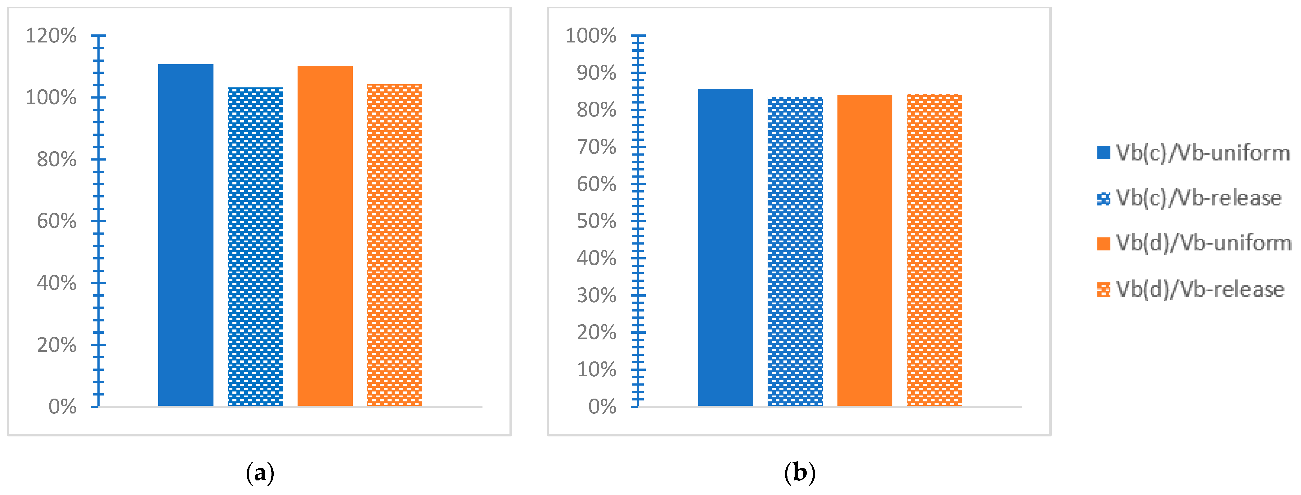
The base shear ratio along the X-axis varies in the range of 80~93%, showing higher values for soil D and the uniform connection (Figure 25a), indicating a relieving consequence of the SSI to the seismic response of the mixed buildings in contrast to the inflexible soil. The base shear along the Y-axis varies close to 109~111% for both soil and connection types (Figure 25b), showing that the deformable soil tends to increase the plot results in contrast to the inflexible soil. Respectively (Figure 26), the base moment ratio at both axes varies in the value range of 36~40% for both soil and connection types. In Figure 27, the Vb(rel)/Vb(uni) and Mb(rel)/Mb(uni) ratios vary with a mean value close to 100%, except for a local observed increase in the Vb(rel)/Vb(uni) ratio up to 109% for the rigid soil assumption on the X-axis, showing that the release connection type tends to overwhelm the structural response.

3.5. Comments on the Six-Story Mixed Model (RC4-ST2)

As displayed in Figure 28a, at the first r/c story of the RC4-ST2 model, the drift ratio along the X-axis presents the greatest value of 0.028 concerning the rigid soil and the release connection and a minimum value of 0.021 for soil D and the uniform connection. On the Y-axis (Figure 28b), the IDR increases up to 0.033 for the rigid soil and the uniform connection, showing a smaller value of 0.0248 for soil D and the same connection.
At the fifth steel story of this model, smaller values of IDR are observed in Figure 29 as compared with the previous ones of the first story (Figure 28). In the fifth story, the IDR along the X-axis varies from 0.009 to 0.013 (Figure 29a), within the “LS performance level” [56]. As displayed in Figure 29b, the drift ratio rises to 0.029 for soil C and the release connection type, while it has a smaller value of 0.011 for the rigid soil and the uniform connection.
In the sixth story, as shown in Figure 30a, the IDR along the X-axis fluctuates within a range of 0.01~0.015 with greater values considering the inflexible base and both connection types compared with the SSI. The IDR along the Y-axis presents values close to 0.021 regarding the rigid soil and both connection types and up to 0.028~0.029 for the SSI consideration, demonstrating a detrimental SSI effect on the seismic response of the mixed buildings (Figure 30b).
Considering the rigid soil assumption, for the uniform connection type, the response plots omit the earthquake cases of Loma Prieta, Kefalonia, and Northridge with angle 90°, and for the release connection, the case of Tabas with angle 90°. Considering the SSI via soil type C, the NLTH analysis plots include, for the uniform connection, the excitations of Landers 90°, San Fernando 0°, and Petrolia 90° while, for the release connection, the excitations of San Fernando and Petrolia with angle 90° are plotted. Regarding soil type D, for the uniform connection, the plots include the results of the accelerograms of San Fernando with angle 0° and Petrolia with angle 90° and, for the release connection, Landers 90°, San Fernando 0°, and Petrolia 90°.
The base shear ratio along the X-axis is observed (Figure 31a) to vary in the value range of 103~111% with bigger values for the uniform connection than for the release connection. In Figure 31b, the base shear ratio on the Y-axis presents values within 83~86%, showing that the SSI consideration for both soil types affects ambiguously the structural response, taking into account the base shear. The base moment ratio varies between 55 and 57% along the X-axis and between 60 and 61% along the Y-axis (Figure 32), indicating a relieving SSI effect against the fixed base assumption.
In Figure 33, the ratio Vb(rel)/Vb(uni) varies within 0.94~1.01 for the considered ground supports, with slightly smaller values considering soils C and D, indicating a positive consequence of the SSI on the mixed model response. However, the ratio Mb(rel)/Mb(uni) varies within 1.04~1.09 in Figure 33, indicating that the uniform connection type, as well as the rigid soil assumption, tends to burden the structural response more than the rest cases.
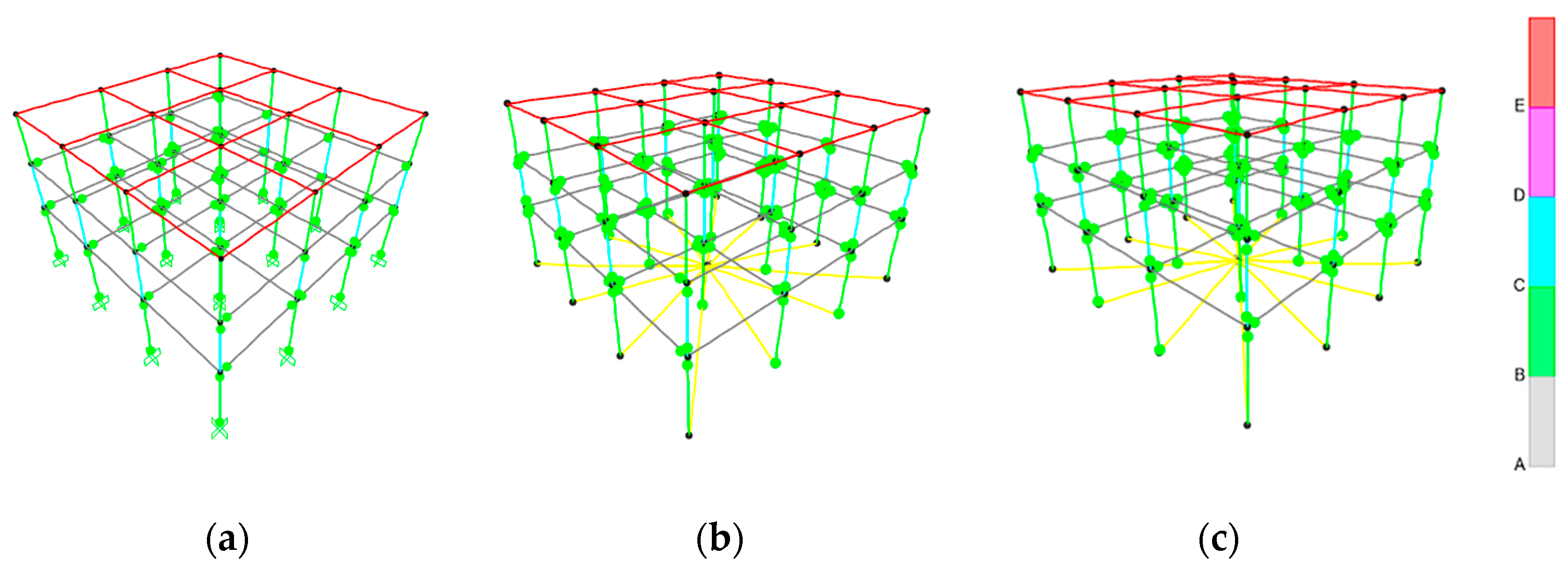
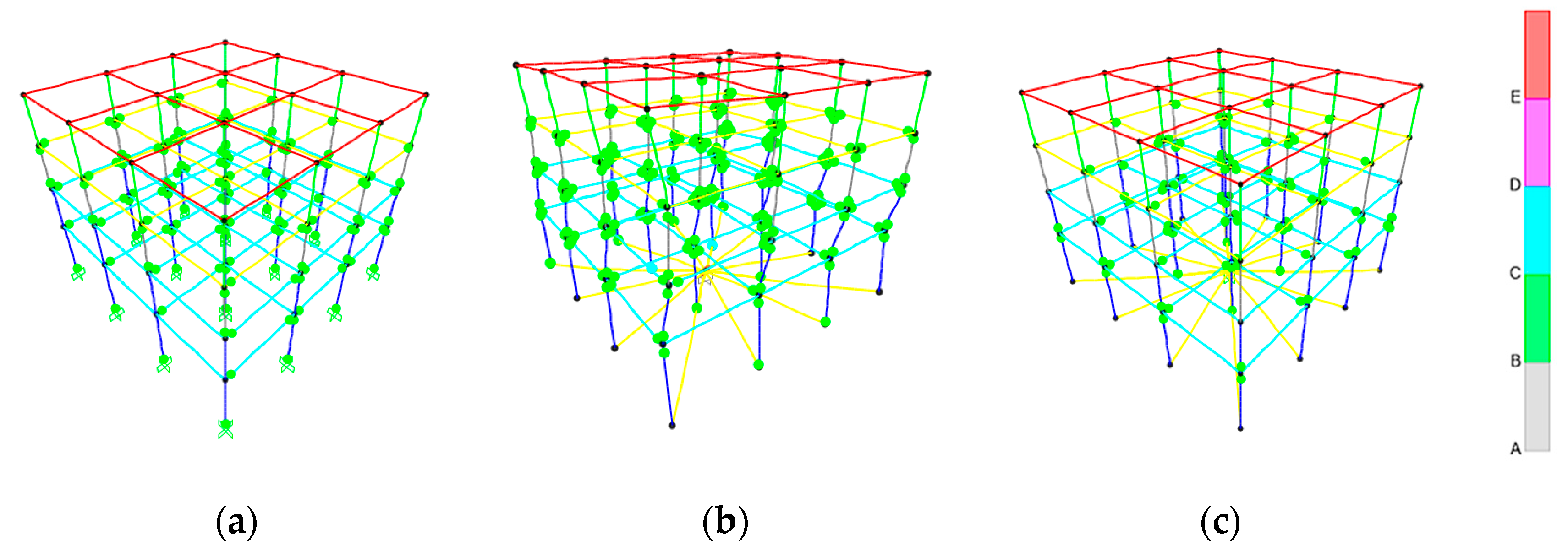
The nonlinear dynamic behavior of the mixed models is observed by the elastoplastic hinges placed at element ends, according to the current regulations, where the following letters are displayed as “A” for the linear/elastic behavior, “B” for the “yielding bending moment limit “ [3,55], “C”, referring to “ultimate yielding bending moment limit” [3,55], “D” for the residual bending moment limit [3,55], and “E” referring to bending moments greater than the previous limits and deformations greater than the “ultimate deformation” [3,55]. Some selected plots of the worst hinge formation are shown in Figure 34 and Figure 35. Figure 34 depicts the worst hinge formation for the mixed model RC2—indicatively for selected excitations for the three supporting conditions, where the hinge behavior is within the previous C limit. In Figure 35, the hinge formation of the RC3-ST1 model is plotted, showing a hinge behavior within the C limit, as previously noted. In general, the hinges of the mixed models show an inelastic behavior more intense for the deformable soil than for the rigid soil (Figure 34 and Figure 35). The hinges tend to show elastic behavior at the upper steel stories and plastic at the lower r/c stories, which is observed as more intense for the SSI consideration than for the rigid soil assumption (Figure 34 and Figure 35). Because of the size of the mixed models, the hinge plots can provide qualitative general remarks, while the dimensionless parameters plots provide numerical estimations.
In addition, in the literature, several studies are available concerning the seismic response and design of building structures, made exclusively by reinforced concrete, e.g., Penelis and Kappos [57] and Fardis [58], or only by structural steel, e.g., Papagiannopoulos et al. [59]. However, a comparison of the building structures composed of either r/c or steel with mixed r/c-steel buildings is limited [15,60]. In addition, the influence of the SSI in the seismic response of mixed r/c-steel buildings has not been studied in depth. The present work qualitatively and, by considering dimensionless parameters, numerically investigates the influence of soil deformability on simple low- to medium-rise mixed buildings in comparison to the typical rigid soil assumption.

4. Conclusions

In the current work, the impact of soil deformability contrary to rigid soil on the seismic response is explored in symmetric mixed r/c‒steel common buildings in three-dimensional conditions for the first time in the literature, to the best of the author’s knowledge. Two soft soil types C and D, as well as the fixed base acting as a reference point, and two connection forms of the steel and reinforced concrete parts, are compared to each other by time-expensive NLTH analyses for strong real earthquakes. Dimensionless response plots are constructed for numerical evaluation, aiming to demonstrate the seismic behavior of the mixed structures as affected by soil deformability compared to the typical rigid soil assumption. Some selected hinge plots are displayed to show the nonlinear hinge behavior under strong earthquakes for the SSI as qualitatively compared to the fixed base assumption. The response plots are discussed in terms of the SSI effect on mixed models to obtain objective conclusions, as listed below.
  • The first story is heavily stressed by soil deformability, as compared with the rigid soil assumption, showing IDR values close to the applicable “CP” limit. Indicatively, the IDR may be greater by even 61~74% for deformable soil in comparison with the corresponding one for rigid soil.
  • Considering soil deformability, the steel story shows increased IDR values, even close to 4%, which is the CP limit, as compared with the r/c part where the corresponding IDR may be less by 32%. The IDR increase in the steel story is more intense for the SSI than for the rigid base and even more obvious for the release connection type than the uniform one. In contrast, for the rigid soil assumption, the greatest IDR of the steel story tends to be smaller than that for the first r/c story by 50~65%.
  • The SSI consideration may cause significant construction deformations, much higher than code restrictions, indicating building failure, while the latter is rather unusual for the rigid soil assumption.
  • The SSI for soil type D tends to result in greater deformations than for soil type C when both are compared with the fixed base assumption.
  • The soil’s deformability results in increased values of the base shear ratio but in smaller values of the base moment ratio. This means that deformable soil burdens the mixed building considering the base shear while favoring the structural response considering the base moment, comparatively with the rigid soil consideration.
  • The release interconnection of the steel and r/c parts tends to affect the base shear by resulting in slightly smaller values and increasing the observed values of the base moment separately, considering the SSI, against the consideration of the rigid soil.
  • The hinges at element ends tend to be burdened more by the SSI than by the rigid soil.
  • Generally, the release interconnection of the steel component on the reinforced concrete one tends to increase the IDR values more accounting for the SSI than for the inflexible soil assumption. In the meantime, increased values of IDR are generally noticed for the inflexible soil and uniform connection, as compared with the other examined cases.
  • The seismic response plots show some cases where a detrimental SSI effect is noticed on the behavior of the mixed model, while in other cases, an advantageous SSI is obvious, indicating an ambiguous SSI effect on the structural response. This means that the design analysis should be performed not only for the usual rigid soil assumption but also considering deformable soil to ensure the boundary conditions are examined and the extreme response parameters are recognized, leading to a safer mixed building conception.

Funding

This research received no external funding.

Data Availability Statement

Data are contained within this article.

Conflicts of Interest

The author declares no conflicts of interest.

References

  1. EN 1992-1-1 Eurocode 2 (EC2); Design of Concrete Structures—Part 1-1: General Rules and Rules for Buildings. European Committee for Standardization: Brussels, Belgium, 2004.
  2. EN 1993-1-1 Eurocode 3 (EC3); Design of Steel Structures—Part 1-1: General Rules and Rules for Buildings. European Committee for Standardization: Brussels, Belgium, 2009.
  3. EN 1998-5 Eurocode 8 (EC8); Design of Structures for Earthquake Resistance—Part 1: General Rules, Seismic Actions and Rules for Buildings, Part 3: Strengthening and Repair of Buildings, Part 5: Foundations, Retaining Structures and Geotechnical Aspects. Part 6: Towers, Masts and Chimneys. European Committee for Standardization: Brussels, Belgium, 2004.
  4. Maley, T.J.; Sullivann, T.J.; Pampanin, S. Issues with the seismic design of mixed MRF Systems. In Proceedings of the 15th World Conference on Earthquake Engineering, Lisboa, Portugal, 24–28 September 2012. [Google Scholar]
  5. Villaverde, R. Seismic design of secondary structures: State of the art. J. Struct. Eng. 1997, 123, 1011–1019. [Google Scholar] [CrossRef]
  6. Askouni, P.K.; Papagiannopoulos, G.A. Seismic Behavior of a Class of Mixed Reinforced Concrete-Steel Buildings Subjected to Near-Fault Motions. Infrastructures 2021, 6, 172. [Google Scholar] [CrossRef]
  7. Askouni, P.K.; Papagiannopoulos, G.A. The Non-Linear Behavior of Mixed Reinforced Concrete–Steel Frames under Strong Earthquakes. Eng. Proc. 2023, 53, 15. [Google Scholar] [CrossRef]
  8. Askouni, P.K.; Papagiannopoulos, G.A. The Seismic Response of Mixed Reinforced Concrete–Steel Buildings Under Near-Fault Earthquakes. In Proceedings of the COMPDYN 2023, 9th International Conference on Computational Methods in Structural Dynamics and Earthquake Engineering, Athens, Greece, 12–14 June 2023. [Google Scholar] [CrossRef]
  9. Askouni, P.K. Τhe Behavior of Hybrid Reinforced Concrete-Steel Buildings under Sequential Ground Excitations. Computation 2023, 11, 102. [Google Scholar] [CrossRef]
  10. Pnevmatikos, N.; Blachowski, B.; Papavasileiou, G. Damage detection of mixed concrete/steel frame subjected to earthquake excitation. In Proceedings of the 7th International Conference on Computational Methods in Structural Dynamics and Earthquake Engineering (COMPDYN 2019), Crete, Greece, 24–26 June 2019. [Google Scholar]
  11. Kaveh, A.; Ardebili, S.R. Optimal design of mixed structures under time-history loading using metaheuristic algorithm. Period. Polytech. Civ. Eng. 2023, 67, 57–64. [Google Scholar] [CrossRef]
  12. Bahri, F.; Bahri, F.; Moeini, M.E. Numerical investigation of a novel concrete-to-steel column splice in mixed structures in height. Structures 2023, 58, 105526. [Google Scholar] [CrossRef]
  13. Kiani, A.; Yang, T.Y.; Kheyroddin, A.; Kafi, M.A.; Naderpour, H. March. Quantification of seismic performance factors of mixed concrete/steel buildings using the FEMA P695 methodology. Structures 2024, 61, 106144. [Google Scholar] [CrossRef]
  14. Fanaie, N.; Shamlou, S.O. Response modification factor of mixed structures. Steel Compos. Struct. 2015, 19, 1449–1466. [Google Scholar] [CrossRef]
  15. Farghaly, A.A. Parametric study on equivalent damping ratio of different composite structural building systems. Steel Compos. Struct. 2013, 14, 349–365. [Google Scholar] [CrossRef]
  16. Huang, W.; Qian, J.; Zhou, Z.; Fu, Q. An approach to equivalent damping ratio of vertically mixed structures based on response error minimization. Soil Dyn. Earthq. Eng. 2015, 72, 119–128. [Google Scholar] [CrossRef]
  17. Sivandi-Pour, A.; Gerami, M.; Kheyroddin, A. Determination of modal damping ratios for non-classically damped rehabilitated steel structures. Iran. J. Sci. Technol. Trans. Civ. Eng. 2015, 39, 81. [Google Scholar]
  18. Sivandi-Pour, A.; Gerami, M.; Kheyroddin, A. Uniform damping ratio for non-classically damped hybrid steel concrete structures. Int. J. Civ. Eng. 2016, 14, 1–11. [Google Scholar] [CrossRef]
  19. Sivandi-Pour, A.; Gerami, M.; Khodayarnezhad, D. Equivalent modal damping ratios for non-classically damped hybrid steel concrete buildings with transitional storey. Struct. Eng. Mech. 2014, 50, 383–401. [Google Scholar]
  20. Papagiannopoulos, G.A. On the modal damping ratios of mixed reinforced concrete–steel buildings. Soil Dyn. Earthq. Eng. 2024, 178, 108481. [Google Scholar] [CrossRef]
  21. Mylonakis, G.; Syngros, C.; Gazetas, G.; Tazoh, T. The role of soil in the collapse of 18 piers of Hanshin Expressway in the Kobe earthquake. Earthq. Eng. Struct. Dyn. 2006, 35, 547–575. [Google Scholar] [CrossRef]
  22. Mylonakis, G.; Gazetas, G. Seismic soil-structure interaction: Beneficial or detrimental? J. Earthq. Eng. 2000, 4, 277–301. [Google Scholar] [CrossRef]
  23. Jahami, A.; Halawi, J.; Temsah, Y.; Jaber, L. Assessment of Soil–Structure Interaction Effects on the Beirut Port Silos Due to the 4 August 2020 Explosion: A Coupled Eulerian–Lagrangian Approach. Infrastructures 2023, 8, 147. [Google Scholar] [CrossRef]
  24. Yanik, A.; Ulus, Y. Soil–Structure Interaction Consideration for Base Isolated Structures under Earthquake Excitation. Buildings 2023, 13, 915. [Google Scholar] [CrossRef]
  25. Azhir, P.; Asgari Marnani, J.; Panji, M.; Rohanimanesh, M.S. A Coupled Finite-Boundary Element Method for Efficient Dynamic Structure-Soil-Structure Interaction Modeling. Math. Comput. Appl. 2024, 29, 24. [Google Scholar] [CrossRef]
  26. Karabalis, D.L.; Beskos, D.E. Dynamic response of 3-D flexible foundations by time domain BEM and FEM. Int. J. Soil Dyn. Earthq. Eng. 1985, 4, 91–101. [Google Scholar] [CrossRef]
  27. Karabalis, D.L. Non-singular time domain BEM with applications to 3D inertial soil–structure interaction. Soil Dyn. Earthq. Eng. 2004, 24, 281–293. [Google Scholar] [CrossRef]
  28. Riaz, M.R.; Motoyama, H.; Hori, M. Review of Soil-Structure Interaction Based on Continuum Mechanics Theory and Use of High Performance Computing. Geosciences 2021, 11, 72. [Google Scholar] [CrossRef]
  29. Pantelidis, L.; Gravanis, E. Elastic Settlement Analysis of Rigid Rectangular Footings on Sands and Clays. Geosciences 2020, 10, 491. [Google Scholar] [CrossRef]
  30. Anand, V.; Kumar, S.R. Seismic soil-structure interaction: A state-of-the-art review. Structures 2018, 16, 317–326. [Google Scholar] [CrossRef]
  31. Barnaure, M.; Manoli, D. Unfavourable seismic behaviour of reinforced concrete structures due to soil structure interaction. IOP Conf. Ser. Earth Environ. Sci. 2019, 362, 12119. [Google Scholar] [CrossRef]
  32. Krishnan, R.; Sivakumar, V.L. The Effect of Soil-Structure Interaction (SSI) on Structural Stability and Sustainability of RC Structures. Civ. Environ. Eng. Rep. 2024, 34, 116–136. [Google Scholar] [CrossRef]
  33. Mata, R.; Nuñez, E.; Hernández, M.; Correa, C.; Bustamante, G. Seismic Performance of RC Moment Frame Buildings Considering SSI Effects: A Case Study of the New Venezuelan Seismic Code. Buildings 2023, 13, 1694. [Google Scholar] [CrossRef]
  34. Wang, J.; Xie, Y.; Guo, T.; Du, Z. Predicting the Influence of Soil–Structure Interaction on Seismic Responses of Reinforced Concrete Frame Buildings Using Convolutional Neural Network. Buildings 2023, 13, 564. [Google Scholar] [CrossRef]
  35. Oz, I.; Senel, S.M.; Palanci, M.; Kalkan, A. Effect of soil-structure interaction on the seismic response of existing low and mid-rise RC buildings. Appl. Sci. 2020, 10, 8357. [Google Scholar] [CrossRef]
  36. Kamal, M.; Inel, M. Correlation between Ground Motion Parameters and Displacement Demands of Mid-Rise RC Buildings on Soft Soils Considering Soil-Structure-Interaction. Buildings 2021, 11, 125. [Google Scholar] [CrossRef]
  37. Askouni, P.K.; Karabalis, D.L. The Modification of the Estimated Seismic Behaviour of R/C Low-Rise Buildings Due to SSI. Buildings 2022, 12, 975. [Google Scholar] [CrossRef]
  38. Askouni, P.K.; Karabalis, D.L. SSI influence on the seismic response of asymmetrical small, low-rise R/C buildings. Structures 2021, 32, 1355–1373. [Google Scholar] [CrossRef]
  39. Askouni, P.K.; Karabalis, D.L. SSI effects on the redistribution of seismic forces in one-storey R/C buildings. Earthq. Struct. 2021, 20, 261–278. [Google Scholar] [CrossRef]
  40. Askouni, P.K.; Karabalis, D.L.; Beskos, D.E. SSI effects on r/c one-storey buildings under seismic loadings. In Proceedings of the EURODYN 2020, XI—International Conference on Structural Dynamics, Athens, Greece, 23–26 November 2020. [Google Scholar] [CrossRef]
  41. Askouni, P.K.; Karabalis, D.L. The Alteration of the Seismic Behaviour of Asymmetrical Low-Rise R/C Buildings due to Soil-Structure Interaction. In Proceedings of the 13th International Congress on Mechanics HSTAM2022, Patras, Greece, 24–27 August 2022. [Google Scholar]
  42. Askouni, P.K.; Karabalis, D.L. The redistribution of seismic forces in low-rise R/C buildings due to Soil-Structure Interaction. In Proceedings of the 10th GRACM International Congress on Computational Mechanics, Athens, Greece, 5–7 July 2021. [Google Scholar]
  43. Mekki, M.; Elachachi, S.M.; Breysse, D.; Zoutat, M. Seismic behavior of RC structures including soil-structure interaction and soil variability effects. Eng. Struct. 2016, 126, 15–26. [Google Scholar] [CrossRef]
  44. Tahghighi, H.; Mohammadi, A. Numerical evaluation of soil–structure interaction effects on the seismic performance and vulnerability of reinforced concrete buildings. Int. J. Geomech. 2020, 20, 04020072. [Google Scholar] [CrossRef]
  45. Altunişik, A.C.; Kalkan, E. Earthquake incidence angle influence on seismic performance of reinforced concrete buildings. Sigma J. Eng. Nat. Sci. 2017, 35, 609–631. [Google Scholar]
  46. Athanatopoulou, A.M. Critical orientation of three correlated seismic components. Eng. Struct. 2005, 27, 301–312. [Google Scholar] [CrossRef]
  47. Altunişik, A.C.; Kalkan, E. Influence of earthquake angle on seismic performance of concrete highway bridges. Građevinar 2023, 75, 1013–1024. [Google Scholar] [CrossRef]
  48. Tehrani, P.; Ghanbari, R. Investigating different methods for application of earthquake records in seismic evaluation of irregular RC bridges considering incident angles. Structures 2021, 32, 1717–1733. [Google Scholar] [CrossRef]
  49. EN 1991-1-1 Eurocode 1 (EC1); Actions on Structures—Part 1-1: General Actions, Densities, Self-Weight, Imposed Loads for Buildings. European Committee for Standardization: Brussels, Belgium, 2001.
  50. EN 1997-1 Eurocode 7 (EC7); Geotechnical Design—Part 1: General Rules. European Committee for Standardization: Brussels, Belgium, 2003.
  51. Mulliken, J.S.; Karabalis, D.L. Discrete model for dynamic through-the-soil coupling of 3-d foundations and structures. Earthq. Eng. Struct. Dyn. 1998, 27, 687–710. [Google Scholar]
  52. SAP 2000; Version 22.2.0; Static and Dynamic Finite Element Analysis of Structures; Computers and Structures (CSI): Berkeley, CA, USA, 2020.
  53. Center for Engineering Strong Motion Data. Available online: www.strongmotioncenter.org (accessed on 3 May 2021).
  54. SeismoSpect. Software for Signal Processing for Ground Motion Records: Version 2023; Seismosoft. Available online: https://seismosoft.com/products/seismospect/ (accessed on 1 April 2024).
  55. ASCE 41-17; Seismic Evaluation and Retrofit of Existing Buildings. American Society of Civil Engineers (ASCE): Reston, VA, USA, 2017.
  56. FEMA-356; Prestandard and Commentary for the Seismic Rehabilitation of Buildings. Federal Emergency Management Agency: Washington, DC, USA, 2000.
  57. Penelis, G.G.; Kappos, A.J. Earthquake-Resistant Concrete Structures, 1st ed.; CRC Press: London, UK, 1997. [Google Scholar] [CrossRef]
  58. Fardis, M.N. Seismic Design, Assessment and Retrofitting of Concrete Buildings: Based on EN-Eurocode 8, 1st ed.; Springer: Berlin/Heidelberg, Germany, 2009. [Google Scholar] [CrossRef]
  59. Papagiannopoulos, G.A.; Hatzigeorgiou, G.D.; Beskos, D.E. Seismic Design Methods for Steel Building Structures, 1st ed.; Springer: Cham, Switzerland, 2021. [Google Scholar] [CrossRef]
  60. Darshini, B. Comparison of seismic behaviour of composite and rcc columns in multistoried commercial building—A review. Int. Res. J. Eng. Technol. 2020, 7, 731–735. [Google Scholar]
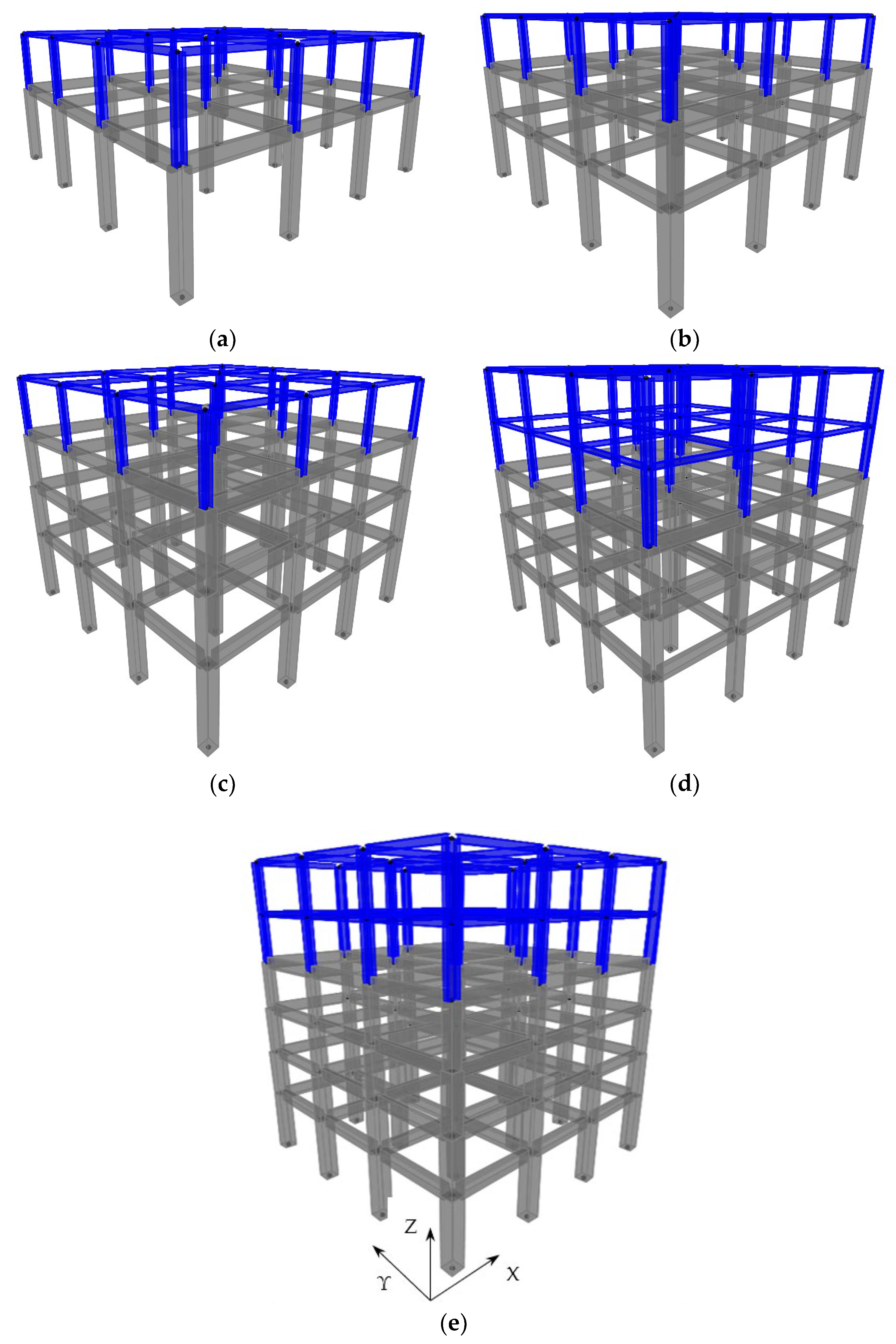
Figure 1. The considered mixed frames (a) RC1-ST1, (b) RC2-ST1, (c) RC3-ST1, (d) RC3-ST2, and (e) RC4-ST2, where gray refers to reinforced concrete as structural material and blue refers to structural steel, with a notation of the global axes system.
Infrastructures 09 00080 g001
Figure 2. Detail of the 3D orientation of steel elements of the steel stories.
Infrastructures 09 00080 g002
Figure 3. Discrete SSI model formed by rigid elements.
Infrastructures 09 00080 g003
Figure 4. A Comparison of the considered earthquake spectra in the two horizontal directions (labeled as “1” or “2” for each earthquake) to the code design spectra considering zone ground acceleration of 0.36·g for soil C (labeled as “EC8-Soil C”) and the respective one for soil D (labeled as “EC8-Soil D”).
Infrastructures 09 00080 g004
Figure 5. Comparison of the IDR along the (a) X-axis and (b) Y-axis at the 1st story, RC1-ST1 building.
Infrastructures 09 00080 g005
Figure 6. Comparison of the IDR along the (a) X-axis and (b) Y-axis at the 2nd story, RC1-ST1 building.
Infrastructures 09 00080 g006
Figure 7. Comparison of the base shear ratio on the (a) X-axis and (b) Y-axis, RC1-ST1 building.
Infrastructures 09 00080 g007
Figure 8. Comparison of the base moment ratio on the (a) X-axis and (b) Y-axis, RC1-ST1 building.
Infrastructures 09 00080 g008
Figure 9. Comparison of the ratios Vb(rel)/Vb(uni) and Mb(rel)/Mb(uni) at the X- and Y-axes, RC1-ST1 building, for “r.s.”, “C”, and “D” soil assumptions.
Infrastructures 09 00080 g009
Figure 10. Comparison of IDR along the (a) X-axis and (b) Y-axis at the 1st story, RC2-ST1 building.
Infrastructures 09 00080 g010
Figure 11. Comparison of IDR along the (a) X-axis and (b) Y-axis at the 2nd story, RC2-ST1 building.
Infrastructures 09 00080 g011
Figure 12. Comparison of the IDR along the (a) X-axis and (b) Y-axis at the 3rd story, RC2-ST1 building.
Infrastructures 09 00080 g012
Figure 13. Comparison of the base shear ratio on the (a) X-axis and (b) Y-axis, RC2-ST1 building.
Infrastructures 09 00080 g013
Figure 14. Comparison of the base moment ratio along the (a) X-axis and (b) Y-axis, RC2-ST1 building.
Infrastructures 09 00080 g014
Figure 15. Comparison of the ratios Vb(rel)/Vb(uni) and Mb(rel)/Mb(uni) on the X- and Y-axes at the RC2-ST1 building for “r.s.”, “C”, and “D” soil assumptions.
Infrastructures 09 00080 g015
Figure 16. IDR along the (a) X-axis and (b) Y-axis at the 1st story, RC3-ST1 building.
Infrastructures 09 00080 g016
Figure 17. IDR along the (a) X-axis and (b) Y-axis at the 2nd story, RC3-ST1 building.
Infrastructures 09 00080 g017
Figure 18. IDR along the (a) X-axis and (b) Y-axis at the 4th story, RC3-ST1 building.
Infrastructures 09 00080 g018
Figure 19. Comparison of the base shear ratio on the (a) X-axis and (b) Y-axis, RC3-ST1 building.
Infrastructures 09 00080 g019
Figure 20. Comparison of the base moment ratio on the (a) X-axis and (b) Y-axis, RC3-ST1 building.
Infrastructures 09 00080 g020
Figure 21. Comparison of the ratios Vb(rel)/Vb(uni) and Mb(rel)/Mb(uni) on the X- and Y-axes at the 4 RC3-ST1 building for “r.s.”, “C”, and “D” soil assumptions.
Infrastructures 09 00080 g021
Figure 22. IDR along the (a) X-axis and (b) Y-axis at the 1st story, RC3-ST2 building.
Infrastructures 09 00080 g022
Figure 23. IDR along the (a) X-axis and (b) Y-axis at the 4th story, RC3-ST2 building.
Infrastructures 09 00080 g023
Figure 24. IDR along the (a) X-axis and (b) Y-axis at the 5th story, RC3-ST2 building.
Infrastructures 09 00080 g024
Figure 25. Comparison of the base shear ratio on the (a) X-axis and (b) Y-axis, RC3-ST2 building.
Infrastructures 09 00080 g025
Figure 26. Comparison of the base moment ratio on the (a) X-axis and (b) Y axis, RC3-ST2 building.
Infrastructures 09 00080 g026
Figure 27. Comparison of the ratios Vb(rel)/Vb(uni) and Mb(rel)/Mb(uni) on the X- and Y-axes at the RC3-ST2 building for “r.s.”, “C”, and “D” soil assumptions.
Infrastructures 09 00080 g027
Figure 28. IDR along the (a) X-axis and (b) Y-axis at the 1st story, RC4-ST2 building.
Infrastructures 09 00080 g028
Figure 29. IDR along the (a) X-axis and (b) Y-axis at the 5th story, RC4-ST2 building.
Infrastructures 09 00080 g029
Figure 30. IDR along the (a) X-axis and (b) Y-axis at the 6th story, RC4-ST2 building.
Infrastructures 09 00080 g030
Figure 31. Comparison of the base shear ratio on the (a) X-axis and (b) Y-axis, RC4-ST2 building.
Infrastructures 09 00080 g031
Figure 32. Comparison of the base moment ratio on the (a) X-axis and (b) Y-axis, RC4-ST2 building.
Infrastructures 09 00080 g032
Figure 33. Comparison of the Vb(rel)/Vb(uni) and Mb(rel)/Mb(uni) on the X- and Y-axes at the RC4-ST2 building for “r.s.”, “C”, and “D” soil assumptions.
Infrastructures 09 00080 g033
Figure 34. Hinge formation for the mixed model RC2-ST1 for (a) rigid soil, release connection, Imperial Valley earthquake with 0°, (b) soil C, release connection, Cape Mendocino earthquake with 90°, and (c) soil D, uniform connection, Cape Mendocino earthquake with 90°.
Infrastructures 09 00080 g034
Figure 35. Hinge formation for the mixed model RC3-ST1 for (a) rigid soil, uniform connection, San Fernando earthquake with 0°, (b) soil C, uniform connection, San Fernando earthquake with 90°, and (c) soil D, release connection, San Fernando earthquake with 0°.
Infrastructures 09 00080 g035
Table 1. Dimensions and reinforcement of cross-sections of structural elements of the mixed models.
RC1-ST1 modelColumns          Beams
storymaterialCross-section (m2)Axial
reinforcement
Vertical
reinforcement
Cross-section (m2)Axial
reinforcement
Vertical
reinforcement
1r/c0.50 × 0.508Φ22Φ8/100.25 × 0.608Φ18Φ8/10
2steelHEA360              IPE270
RC2-ST1 modelColumns            Beams
StorymaterialCross-section (m2)Axial reinforcementVertical reinforcementCross-section (m2)Axial
reinforcement
Vertical
reinforcement
1r / c0.55 × 0.5516Φ20Φ8/100.25 × 0.608Φ20, 8Φ10Φ8/10
2r/c0.50 × 0.508Φ20, 8Φ10Φ8/100.25 × 0.608Φ18Φ8/10
3steelHEA360              IPE270
RC3-ST1 modelColumns            Beams
StorymaterialCross-section (m2)Axial
reinforcement
Vertical
reinforcement
Cross-section (m2)Axial
reinforcement
Vertical
reinforcement
1r/c0.60 × 0.6016Φ20Φ8/100.25 × 0.708Φ20, 8Φ10Φ8/10
2r/c0.60 × 0.608Φ20, 8Φ16Φ8/100.25 × 0.708Φ20, 8Φ10Φ8/10
3r/c0.50 × 0.508Φ20, 8Φ10Φ8/100.25 × 0.608Φ18Φ8/10
4steelHEA360              IPE270
RC3-ST2 modelColumns            Beams
StorymaterialCross-section (m2)Axial reinforcementVertical
reinforcement
Cross-
section (m2)
Axial
reinforcement
Vertical
reinforcement
1r/c0.70 × 0.708Φ22, 16Φ20Φ8/100.25 × 0.708Φ20, 8Φ16Φ8/10
2r/c0.70 × 0.7016Φ20Φ8/100.25 × 0.702Φ20, 3Φ10Φ8/10
3r/c0.70 × 0.708Φ20, 8Φ10Φ8/100.25 × 0.608Φ18Φ8/10
4steelHEΒ500              IPE360
5steelHEΒ500              IPE300
RC4-ST2 modelColumns            Beams
storymaterialCross-
section (m2)
Axial
reinforcement
Vertical
reinforcement
Cross-section (m2)Axial
reinforcement
Vertical
reinforcement
1r/c0.70 × 0.7032Φ20Φ8/100.25 × 0.708Φ20, 8Φ10Φ8/10
2r/c0.70 × 0.7016Φ20Φ8/100.25 × 0.708Φ18Φ8/10
3r/c0.70 × 0.7016Φ20Φ8/100.25 × 0.708Φ18Φ8/10
4r/c0.70 × 0.7016Φ20Φ8/100.25 × 0.708Φ18Φ8/10
5steelHEA500              IPE400
6steelHEA500              IPE440
Table 2. Mass, stiffness, and damping parameters concerning the 1D discrete foundation soil interaction model.
DirectionMass Ratio βEquivalent Radius roVirtual Soil Mass mvStatic Stiffness KDamping C
Vertical ( 1 ν ) 4 · m ρ r o 3 2 a π 0.27 m β 4.7 G a 1 ν 0.8 a V s K
Horizontal ( 7 8 ν ) 32 ( 1 ν ) · m ρ r o 3 2 a π 0.095 m β 9.2 G a 1 ν 0.163 a V s K
Rocking 3 ( 1 ν ) 5 · m ρ r o 5 2 a 3 π 4 0.24 m β 4.0 G a 3 1 ν 0.6 a V s K
Torsion m ρ r o 5 2 a 3 π 4 0.045 m β 8.31 G a 3 0.127 a V s K
a refers to the half-width of a square foundation, V s = G / ρ refers to shear wave velocity, G refers to shear modulus, and ρ is soil density.
Table 3. First eigenperiod of 3D mixed buildings on rigid soil or considering deformable soil.
Mixed BuildingFirst Eigenperiod (sec)
Rigid SoilSoil CSoil D
UniformReleaseUniformReleaseUniformRelease
RC1-ST10.3990.4290.7750.7770.7820.784
RC2-ST10.5060.5220.9100.9110.9190.920
RC3-ST10.5590.5711.0401.0401.0511.052
RC3-ST20.5810.6011.1351.1351.1481.148
RC4-ST20.4980.5091.0761.1171.0901.131
Table 4. Earthquakes considered in the NLTH analysis of mixed models.
Earthquake and LocationYearEarthquake Recording StationPlot NameDuration (sec)MwPGA (g)
San Fernando (USA)1971Pacoima DamPaco20.486.61.17/1.08
Tabas (Iran)1978TabasTabas63.487.10.93/1.10
Imperial Valley (USA)1979El Centro Array 6Array36.906.50.34/0.46
Superstition Hills (USA)1987Parachute Test SiteHills22.406.50.45/0.38
Loma Prieta (USA)1989Los GatosLos Gatos25.057.00.56/0.61
Cape Mendocino (USA)1992PetroliaPetrolia60.006.90.66/0.59
Landers (USA)1992Lucerne ValleyLanders48.057.30.81/0.73
Northridge (USA)1994Sylmar Converter St.Sylmar28.486.70.37/0.58
Kobe (Japan)1995TakatoriKobe41.156.90.61/0.62
Chi-Chi (Taiwan)1999TCU 052Taiwan90.017.60.50/0.36
Kefalonia (Greece)2014LixouriLixouri67.746.10.67/0.60
Disclaimer/Publisher’s Note: The statements, opinions and data contained in all publications are solely those of the individual author(s) and contributor(s) and not of MDPI and/or the editor(s). MDPI and/or the editor(s) disclaim responsibility for any injury to people or property resulting from any ideas, methods, instructions or products referred to in the content.