Article

Numerical Modeling and Performance Evaluation of Carbon Fiber-Reinforced Polymer-Strengthened Concrete Culverts against Water-Induced Corrosion

1
Department of Civil Engineering, Ghulam Ishaq Khan Institute of Engineering Sciences and Technology, Topi 23640, Pakistan
2
Department of Building Engineering, Energy Systems and Sustainability Science, Faculty of Engineering and Sustainable Development, University of Gävle, 801 76 Gävle, Sweden
*
Author to whom correspondence should be addressed.
Infrastructures 2024, 9(5), 82; https://doi.org/10.3390/infrastructures9050082
Submission received: 23 February 2024 / Revised: 15 April 2024 / Accepted: 17 April 2024 / Published: 6 May 2024

Abstract

:
Culverts fulfill the vital function of safely channeling water beneath railway tracks, highways, and overpasses. They serve various purposes, including facilitating drainage in areas such as watercourses, drainage zones, and regions with restricted ground-bearing capacity. Precast reinforced concrete (RC) box culverts are a popular choice because they are strong, durable, rigid, and economical. However, culverts are prone to corrosion due to exposure to a range of environmental factors and aggressive chemicals. Therefore, enhancing the design and construction of this crucial infrastructure is imperative to effectively combat corrosion and to adhere to modern standards of reliability and affordability. In this study, carbon fiber-reinforced polymer (CFRP) was used to strengthen corroded culverts, with promising potential to improve safety and longevity in these structures. This study compared the behavior of corroded RC box culverts to CFRP-strengthened ones using the finite element method (FEM). It explored the impact of varying the damage thicknesses owing to corrosion, ranging from 0 mm to 20 mm, on the structural performance of the box culverts. The results showed that the CFRP model exhibited a substantial 25% increase in the capacity and reduced the damage compared to the reference model. Moreover, a parametric study was conducted for establishing a cost-effective design, in which numerous CFRP strip configurations were examined for a damaged-culvert model. The results indicated that a complete CFRP sheet was most effective for the maximum design capacity and repair effectiveness. The study’s outcomes provide valuable insights for professionals engaged in enhancing the strength of box culverts, aiming to increase the capacity, enhance the stability, and strengthen corroded culverts.

1. Introduction

Culverts are engineered structures designed to facilitate the passage of water beneath roads, railways, and other forms of infrastructures typically made of concrete or masonry, and are subjected to a variety of stresses, including bending, shear, and torsion. A culvert plays a vital role in a drainage system by managing water flow and offering a reliable pathway for water to pass through highway and railway embankments, effectively preventing flooding [1]. Culverts come in two main varieties: flexible and rigid. Concrete rigid culverts are made to be relatively distortion-free when subjected to bending loads. Flexible culverts made of steel are engineered to work with the soil’s structure and transmit loads in a special way [2]. A culvert type’s suitability is decided by how simple it is to construct and how much drainage capacity it can accommodate. Box culvert structures are cost-effective thanks to their exceptionally high rigidity resulting from monolithic action, thus eliminating the need for isolated foundations. Box culverts or single-cell culverts are employed for smaller discharges, while larger discharges typically necessitate the use of multi-cell or multi-bin culverts [3]. A box culverts’ top slab is designed to bear the live loads applied by driven automobiles. Similarly, the base slab and walls are made to withstand both the internal hydrostatic pressure and external earth pressure, respectively [4]. Over time, culverts can deteriorate owing to corrosion, overloading, or other factors. This can lead to structural failure, which can have serious consequences [5]. As society advances, axle loads, traffic volume, and density inevitably increase, posing a threat to the operational safety of older deteriorated culverts [6]. Hence, a rigorous and economic performance assessment of culverts is important to mitigate risk and ensure a safe transportation system. Culverts, being exposed to various environmental elements and aggressive chemicals, are prone to corrosion-induced deterioration [7]. Traditional materials such as steel and concrete are susceptible to corrosion, which can significantly diminish the culvert’s service life and load-carrying capacity. The infiltration of water and the presence of chloride ions exacerbate the corrosion process, necessitating effective corrosion mitigation strategies [6]. Rectangular reinforced concrete (RC) culverts utilized in sewage drainage systems are susceptible to rapid deterioration due to the highly corrosive environment. This corrosion can occur through various mechanisms, including physical erosion from sewage flow, chemical reactions with acidic sewage solutes and gases, and biological degradation by microorganisms. These mechanisms can all lead to considerable weakening of the culvert structure, thus reducing its cross-sectional area, compromising the integrity of steel reinforcement, causing cracks and leaks, and ultimately shortening the culvert’s service life [8].
A noticeable number of studies have recently been conducted on the evaluation, experimental analysis, and numerical analysis of box culverts. Gong et al. [7] looked into the failure mechanism of RC box culverts using experimental and numerical assessments. The finite element method (FEM) was used by Anil and Ali [9] to verify the experimental results obtained for a box culvert. Moradi et al. [10] concluded that FEM tools might reasonably accurately and with less physical efforts predict the structural behavior of culverts, confirming the experimental research done with FEM by Maximos et al. [11] and Garg [12]. To investigate the effects of various loading situations on the slab and sides of precast RC U-shaped box culverts, Zenagebriel et al. [13] employed both experimental and numerical methods.
Several studies have demonstrated a substantial improvement in the load-carrying capacity achieved through the carbon fiber-reinforced polymer (CFRP) strengthening of culverts. Reinforcement effectively redistributes applied loads, delaying the onset of critical failure mechanisms such as cracking and deformation [14]. Analytical models and experimental studies displayed that CFRP retrofitting can lead to the enhanced load–deflection behavior, enabling the culvert to withstand higher loads and traffic conditions. The effectiveness of CFRP strengthening for culverts has been exhibited in various real-world applications. Case studies from different geographical locations and in various environmental conditions showed the successful implementation of CFRP to improve both the load-carrying capacity and corrosion resistance [15].
The adoption of fiber-reinforced polymer (FRP) materials, particularly CFRP, has garnered remarkable interest in civil engineering applications because of their outstanding mechanical properties, corrosion resistance, and lightweight nature [16]. One significant area of interest lies in the rehabilitation and enhancement of culverts, which are essential components of transportation and drainage infrastructure. Al-Rifai et al. [14] found that CFRP wrapping can increase the load-carrying capacity of culverts by up to 50%. In another study carried out by Bakkour et al. [17], FEM was employed to examine the impact of glass fiber-reinforced polymer (GFRP) on the model parameters of an RC box culvert. Their findings indicated that the inclusion of GFRP led to an increase in the period and mode shapes of the culvert, signifying an enhancement in its dynamic behavior. El-Sheikh et al. [18] experimentally assessed the use of CFRP composites to strengthen concrete box culverts. The outcomes demonstrated that CFRP composites effectively improved the load-carrying capacity and flexural stiffness of the culverts.
Hassan et al. [15] provided a summary of the findings from previous studies on the application of FRP composites for strengthening concrete box culverts. They discussed different types of FRP composites that have been utilized, the methods of strengthening, and the factors affecting the effectiveness of strengthening. CFRP strengthening has shown to considerably increase the load-carrying capacity of culverts [19]. The deterioration of culverts over time, often attributed to factors such as traffic loading, environmental conditions, and corrosive agents, can lead to the reduced structural integrity and compromised functionality [20]. CFRP offers a potential solution to these issues by providing the increased strength, stiffness, and corrosion resistance [18].
In summary, researchers have predominantly focused on conducting experimental studies on box culverts, evaluating various aspects such as culvert strengthening and capacity assessment. However, given the time and cost constraints associated with experimental studies, FEM has emerged as a more widely adopted technique for the structural analysis and improvements. The FEM Abaqus software has been widely utilized in numerous studies related to culverts for design and analysis purposes [13,21,22,23,24]. In this article, our focus is specifically on addressing the corroded area of culverts, namely the bottom of the top slab, using CFRP, rather than the entire culvert model. This study aims to explore the effectiveness of employing CFRP strengthening techniques, in the form of CFRP sheets and strips, to enhance the load-carrying capacity of corroded culverts while concurrently addressing the challenges associated with corrosion using FEM. The research presented is anticipated to offer valuable insights for professionals involved in bolstering the strength of box culverts, with the goal of enhancing the capacity, improving the stability, and strengthening corroded culverts.
The idea of using CFRP strengthening techniques including CFRP sheets is common in structural elements, such as beams and others [16,25,26,27]. Moon et al. [25] examined RC beams with unidirectional/bidirectional CFRP layouts and wrapped CFRP strips. Their analyses revealed that bidirectional CFRP provides better performance compared to unidirectional CFRP. They also determined the favorable layout and quantity of CFRP for beam strengthening in their study. Similarly, Tanarslan [28] performed an experimental program to assess the effectiveness of inclined CFRP strip usage in enhancing the ultimate shear capacity of concrete. Six beams were fabricated with shear deficiency, and various strengthening methods were applied. Their test results indicated the increased strength in all specimens with inclined CFRP strips, without delamination occurrence. Their study contributes to understanding the behavior and strength of RC beams strengthened with inclined CFRP strips. However, few studies have considered the application of CFRP in culverts [14,29], and the benefits of this strengthening method, specifically using strips, have yet to be fully investigated and implemented in culverts. Furthermore, the mitigation of corrosion-affected culverts through CFRP-based retrofitting has not been previously considered. This study uniquely assesses the effectiveness of this method in depth to propose an efficient and cost-effective method for the improvement of the culvert structures’ performance. The entire study plan is illustrated in Figure 1.

2. Materials and Methods

2.1. Geometric Description of Model

The numerical model was developed based on the experimental research of Maximos et al. [11]. The chosen geometry and reinforcement detailing of the FEM model incorporated reinforcement according to the American Society of Testing and Materials (ASTM) C1577 [30] standard for culverts. Figure 2 depicts the geometry of the box culvert along with the steel reinforcement cage modeled in Abaqus. The specimen’s dimensions were 1220 × 2120 × 203 mm, where the long-span length and inner short lengths of the culverts were represented by the first two dimensions, and the slab and wall thickness by the third. The reinforcement cage was composed of bars spaced 180 mm apart with a diameter of 10 mm.

2.2. Constitutive Modeling of Concrete and Steel

To simulate the constitutive behavior of concrete, this study employed a concrete damage plasticity (CDP) model [31]. The material information on the culvert in the current study [32] and the properties of steel and concrete are listed in Table 1. The CDP model integrates the plastic behavior into the response and is a continuum-based damage model specially proposed for concrete.
In order to define the concrete stress–strain relationship in compression, the stress σ c and inelastic strain ε c i n , respectively, are utilized to denote the stress and strain values, while d c represents the damage variable in compression, which is a function of inelastic strain and may vary from zero (indicating a material without damage) to one (indicating a fully damaged material). Hence, the total strain values can be transformed into inelastic strains ε c i n = ε c ε 0 c e l , where ε c is the total strain and ε 0 c e l = σ c E 0 . The damage curve’s precision is verified by assessing the values of the plastic strain ε c p l .
ε c p l = ε c i n d c ( 1 d c ) σ c E 0
The behavior of RC under tension is modeled using the post-failure tensile stress–strain correlation of concrete. This relationship considers factors such as tension stiffening, the interaction between steel and concrete, and strain softening. In developing this model, the following parameters need to be defined: Young’s modulus E 0 , tensile stress σ t , cracking strain values ε t c r , and damage parameter values d t . The cracking strain is computed as ε t c r = ε t ε 0 t e l , where ε 0 t e l = σ t E 0 . Precautionary measures should also be taken to guarantee that the plastic strain values do not drop or turn negative as stress increases.
ε t p l = ε t c r d t ( 1 d t ) σ t E 0
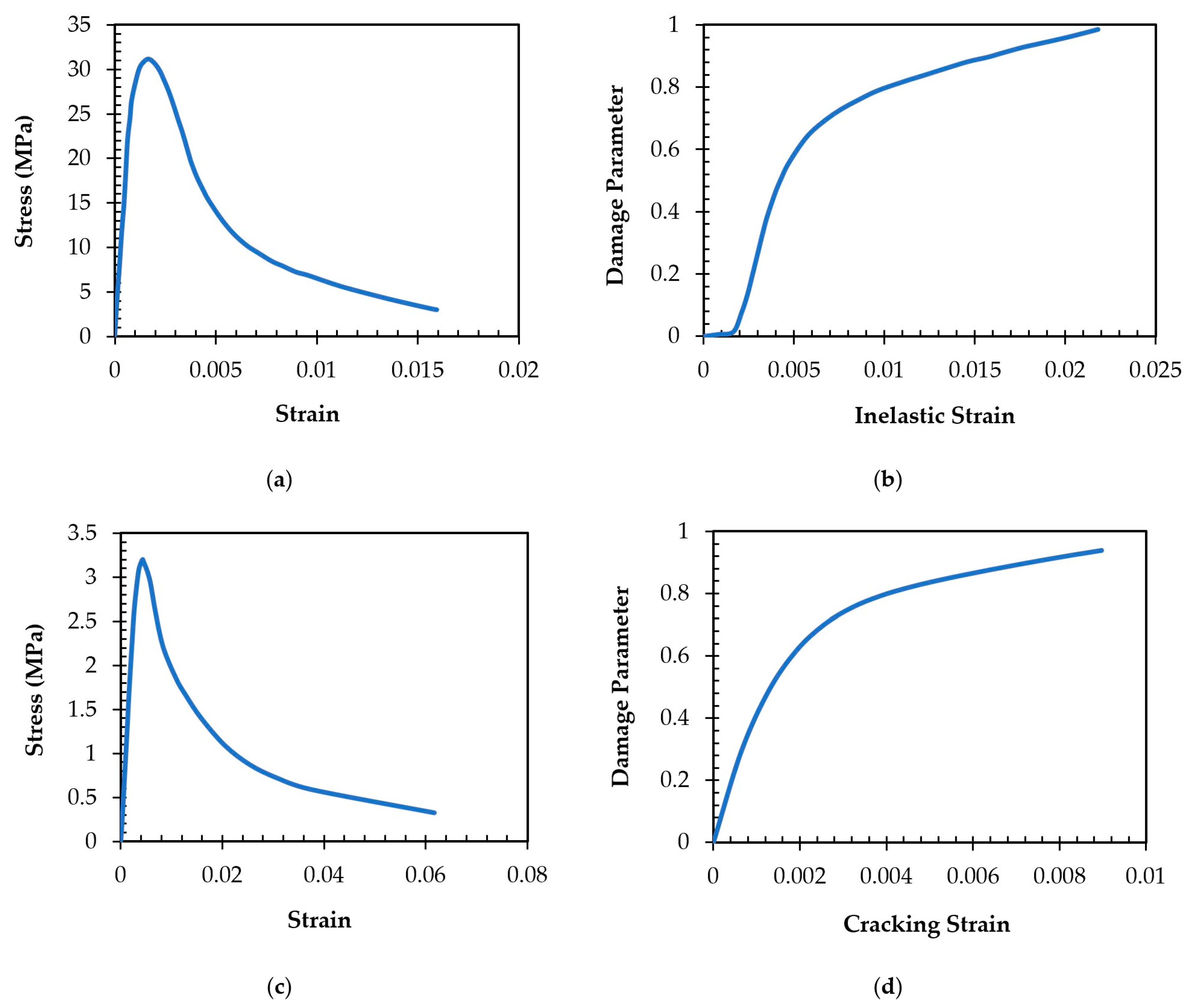
The concrete response in uniaxial stress–strain is represented in Figure 3a, characterized by the progression and initiation of the compression damage until it reaches the point of the ultimate compressive strain. The characterization of concrete and its behavior is necessary for understanding and predicting failure mechanisms and failure loadings in concrete structures, respectively. The CDP model characterizes damage initiation during uniaxial compression loading, commencing promptly after loading initiation and evolving rapidly in the ascending segment of the stress–strain curve. As loading progresses, the rate of damage escalation increases, reaching its maximum before transitioning into the softening phase, where the rate of the damage increase diminishes. The relationship between the damage and inelastic strain is displayed in Figure 3b and found to be in a good agreement with the findings from experimental studies [33]. The analytical expression for d c   [34] is given in the following:
d c = 1 σ c E 0 ( ε c ε c p l )
The two-phase approach to the simulation of the uniaxial stress and strain behavior is followed in the context of tensile loading, as depicted in Figure 3c. Phase one corresponds to the linear elastic concrete behavior up to the point when the tensile strength is achieved. Phase two corresponds to the propagation of the crack initiation in concrete, resulting in a non-linear stress–strain relationship. This behavior is important in the improvement of the design and analysis of structures of concrete, allowing for the accurate prediction of the concrete performance under tensile loading. Figure 3d illustrates the link between the cracking strain and the tension damage variable. The analytical expression for d t   [34] is provided below:
d t = 1 σ t E 0 ( ε t ε t p l )
An elastoplastic constitutive model was utilized for the simulation of steel due to its behavior, which is characterized by both the elastic and plastic regions described by Young’s modulus and post-yield Young’s modulus. Figure 4 provides a pictorial representation of the steel’s typical stress and strain behavior. The bilinear behavior indicates the plastic phase characteristics, which exhibit the typical reinforcement relationship between the stress and strain integrated into the model [35,36].
The plastic flow of the material was simulated in a CDP model through flow parameters, which included the dilation angle (ψ), eccentricity (e), relationship between biaxial and axial stress σ b 0 σ c 0 , a coefficient that determines the deviatoric cross-shaped sections (K), and viscosity parameter (μ). In this investigation, the CDP model flow parameters of the concrete material are derived from prior research findings [37,38,39]. The CDP model’s plastic flow parameters are summarized in Table 2.

2.3. Modeling of Corrosion

Research has indicated that the thickness of corrosion increases over time. A study [36] displayed that the corrosion thickness on a culvert increased over time from 0 mm during its first several years of service to 60 mm after 32 years of service. The study established that a steel bar deterioration model should also be considered with a concrete deterioration model to analyze the drainage culvert performance. When steel bars corrode, the longitudinal bars on the tension side corrode, while the bars on the compression side, longitudinal bars, are ignored owing to their non-contact with the source of corrosion. It is assumed that the longitudinal bars on the tension side are unaffected when the depth of corrosion is below 30 mm (normal concrete cover thickness), when this depth is between 30 mm and 42 mm, the longitudinal bar disappears, i.e., when the longitudinal steel bar’s diameter is included in the corrosion depth. The cross-sectional area decreases linearly with a concrete corrosion thickness between 30 mm and 42 mm of the corrosion depth, and the steel bar’s strength change is not considered. The deterioration of the steel bar can be influenced by several causes in real-world situations, including the interaction between layer passivation, the action of various chemicals, and non-ideal Fick diffusion [8,40]. Studies in the past illustrated that the structural failure of a culvert mostly occurs after full corrosion of steel bars. Concrete gradually loses the strength at the location where corrosion occurs [8]. Corrosion of steel bars involves a complexity that requires simplification for analysis. In this context, assumptions regarding steel bars are simplified. The safety of a box culvert assumed to remain intact until the concrete cover loses its full strength and corrosion impacts steel reinforcement, potentially leading to the strength degradation issues.
To consider the corroded area in the culvert, the thickness of the bottom portion of the top culvert slab is considered to be damaged gradually. The thickness of the slab is then reduced to demonstrate the decrease in the strength of the culvert. After the thickness of the slab has been corroded, CFRP is applied to that location, and the regained strength is recorded. This reduction in the thickness in the culvert slab usually occurs within the first 5 to 10 years, and if CFRP is applied to corroded culverts that are 5 to 10 years old, it can increase the service life and strength of the culverts. However, the operational challenges associated with applying CFRP to older culverts, particularly those already in place, may not be economically feasible. Therefore, the advantage of applying CFRP in new culverts to enhance their durability and longevity from the outset is deemed more practical.

2.4. Constitutive Modeling of CFRP

CFRP is a composite material consisting of carbon fibers embedded in a polymer matrix. In this study, carbon fiber reinforcement is combined with an epoxy resin as the polymer matrix to create CFRP [41]. The use of epoxy resin as the polymer matrix ensures strong adhesion between the carbon fibers and the surrounding material, enhancing the mechanical properties and durability of the composite. The utilization of FEM techniques for CFRP modeling holds immense significance in understanding the mechanical behavior of these composites under various loading conditions. Abaqus provides a variety of material models for CFRP, including orthotropic elastic, plastic, lamina, and damage models. These models can be employed to simulate the behavior of CFRP structures under a variety of loading conditions. In this research, lamina elastic modeling with a CFRP thickness of 0.25 mm was used, and the Hashin damage criteria were studied for each model. The Hashin damage is a progressive damage model that can be utilized to simulate the failure of CFRP structures. The model is based on the work of Hashin [42], who developed a framework for predicting the failure of composite materials. Table 3 shows the material properties employed for CFRP modeling, as taken from the literature [41,43,44]. Table 4 and Table 5 present the Hashin damage and Hashin damage evolution (energy), respectively, for CFRP. E1, E2, and G12 are the material properties of undamped status, and u12 is Poisson’s ratio. E3, G13, and G23 are the elastic modulus of the interface [42,44]. More specifically, G12, G23, and G13 are the shear modulus in planes 1–2, 2–3, and 1–3, respectively [42].

2.5. Boundary Conditions, Interactions, and Loading

The technique of embedded elements was employed to establish a bond between steel reinforcement and concrete. This involves embedding steel cages into concrete through the interaction module in the constraints and identifying the host element as concrete. As a result, the rebar elements move in the same direction as the host concrete elements due to the existence of a perfect bond between them, in accordance with the fundamental assumption of the perfect adhesion between concrete and steel bars in RC. This technique of modeling steel reinforcement overcomes the issue of mesh restriction that occurs in discrete and smeared models by evaluating steel reinforcement and concrete elements separately for the stiffness. The embedded method is highly beneficial when applied to intricate models. However, it increases the degrees of freedom and number of nodes, leading to longer computation times and higher costs [45]. For the interaction between concrete and CFRP, this research work assumed a perfect bond between concrete and CFRP, following the approach adopted in previous studies. This perfect-bond assumption allowed for the modeling of debonding by simulating the cracking and crushing of concrete at the interface between concrete and CFRP, as described in references [14,46].
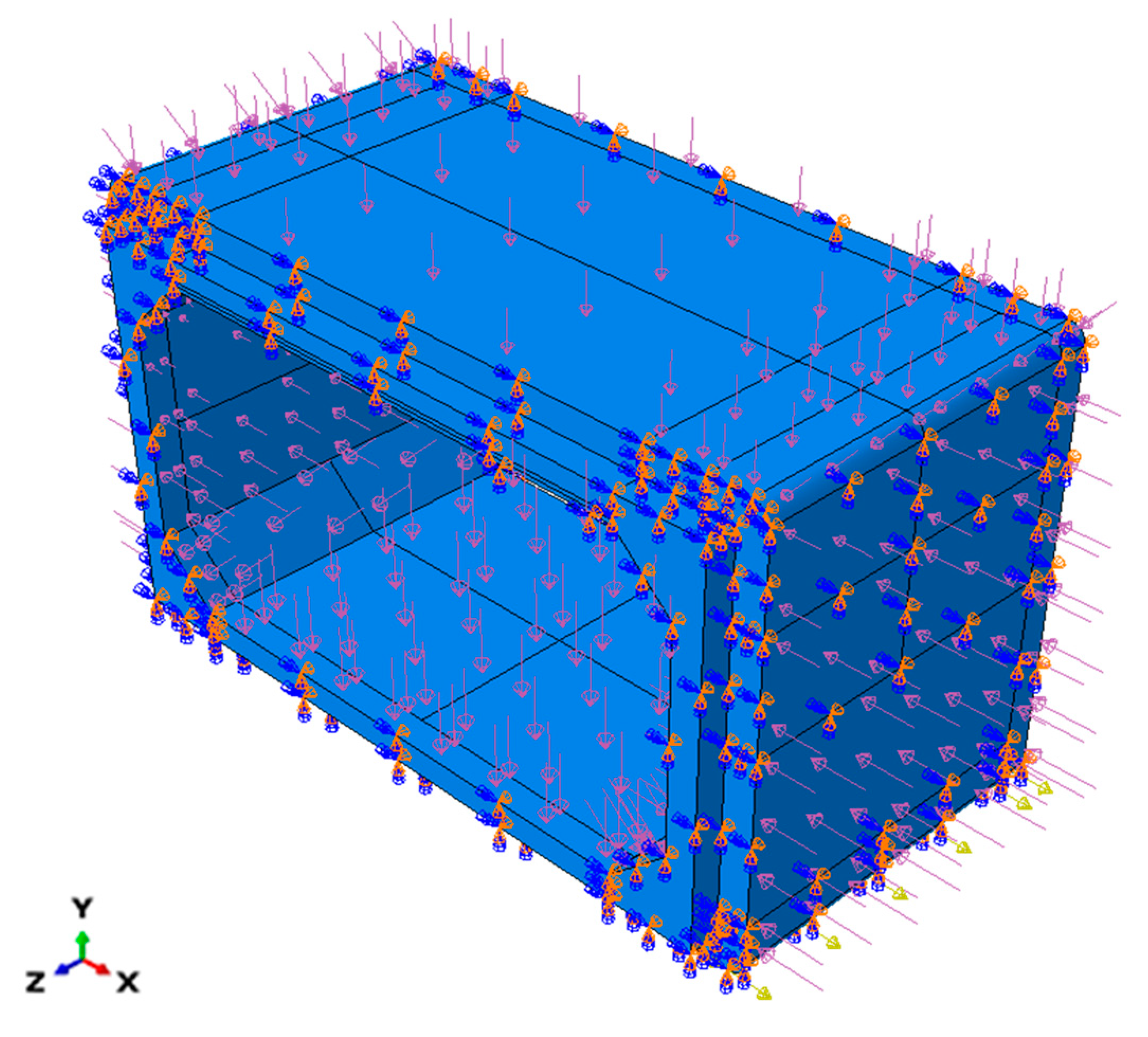
To replicate field conditions, fixed boundary conditions were utilized to model the bottom end of the culvert as a fixed foundation, while the remaining surfaces were constrained appropriately with the required boundary conditions. The model was then loaded with several loads, incorporating traffic load, pore water pressure outside the culvert, water pressure inside the culvert, and active earth pressure on the side walls. To produce a surcharge, a 0.3 m layer of soil and a layer of asphalt with a thickness of 75 mm were additionally put onto the top surface of the culvert slab. These loads’ values were taken from the literature [8,9]. The model’s loading and boundary conditions are depicted in Figure 5.

2.6. Validation of Model and Mesh Sensitivity Analysis

A numerical model of the culvert was created in order to verify the behavior and evaluate the effectiveness of the proposed strengthening technique. This model was developed based on the experimental work of Maximos et al. [11]. A precast box culvert with full-scale dimensions as per the ASTM standards [30,47] was adopted in their study. In the experimental arrangement, a footprint plate was employed to provide a wheel load to the top slab of the box culvert, and loading continued until structural failure occurred. Failure was noted when cracks appeared in the side walls’ negative-moment areas, manifesting at a load of 24.5 t or 244.65 kN.
To create the numerical model of the tested specimen, the methodologies outlined in Section 2.1, Section 2.2, Section 2.3, Section 2.4 and Section 2.5 were followed to replicate the constitutive behavior of the materials and incorporate the necessary modeling specifications. Figure 6 displays the tested specimen’s numerical representation for validation of the model.
The load–deflection response of the structure was examined at the loading point for both steel and concrete using various mesh sizes in order to perform calibration of the model. Three-dimensional wire elements were employed to demonstrate reinforcements in the FEM analysis, while three-dimensional solid elements were utilized for the concrete components [13]. Three-dimensional, two-node (T3D2) elements were used to exhibit the reinforcement components. T3D2 elements work well for modeling structures that are thin and linear, enabling axial loading along the element without supporting perpendicular moments or forces. Conversely, continuum, 3D, and 8-node elements with reduced integration were utilized to mesh the concrete elements (C3D8R). There are fewer integration points on these linear brick elements, C3D8R elements, commonly adopted for the stress analysis.
In the mesh convergence analysis, different mesh sizes were employed for both concrete and reinforcement, including 200 mm, 100 mm, 50 mm, and 20 mm. In general, a coarser mesh accelerates the convergence of the solution, whereas a finer mesh results in higher processing costs but yields more accurate results. The results of the mesh convergence analysis are detailed in validation of the model. Figure 7a illustrates the meshing approach utilized in this study.
Figure 7b presents the analysis results, and Table 6 compares the ultimate load and deflection responses for structures having different mesh sizes. Upon examination of Table 6 and Figure 7a, it was found that setting the mesh size to 50 mm reduced the amount of errors in the results. Additionally, results with small changes were consistently obtained when the mesh size was smaller than 50 mm. Although the outputs were not found to be significantly impacted by the mesh size owing to the small element size, a slightly larger element size was chosen to decrease the computational time.
A mesh size of 100 mm was deemed optimal for both reinforcing steel and concrete components, striking a balance between the model performance and computational efficiency [48]. This mesh size offered an ultimate capacity that was similar to the results of the experiment, with the test specimen showing a 24.5-t ultimate capacity, while FEM indicated 27-t ultimate capacity at failure.
Moreover, the crack patterns found by Maximos et al. [11] closely matched those that the FEM model predicted, as depicted in Figure 8. Consequently, the numerical modeling parameters signified strong correctness with the experimental findings, a 0.9 experiment/FEM ratio, and a predicted error value of about 10%.

3. Results and Discussion

3.1. Comparison of CFRP-Strengthened and Reference Model

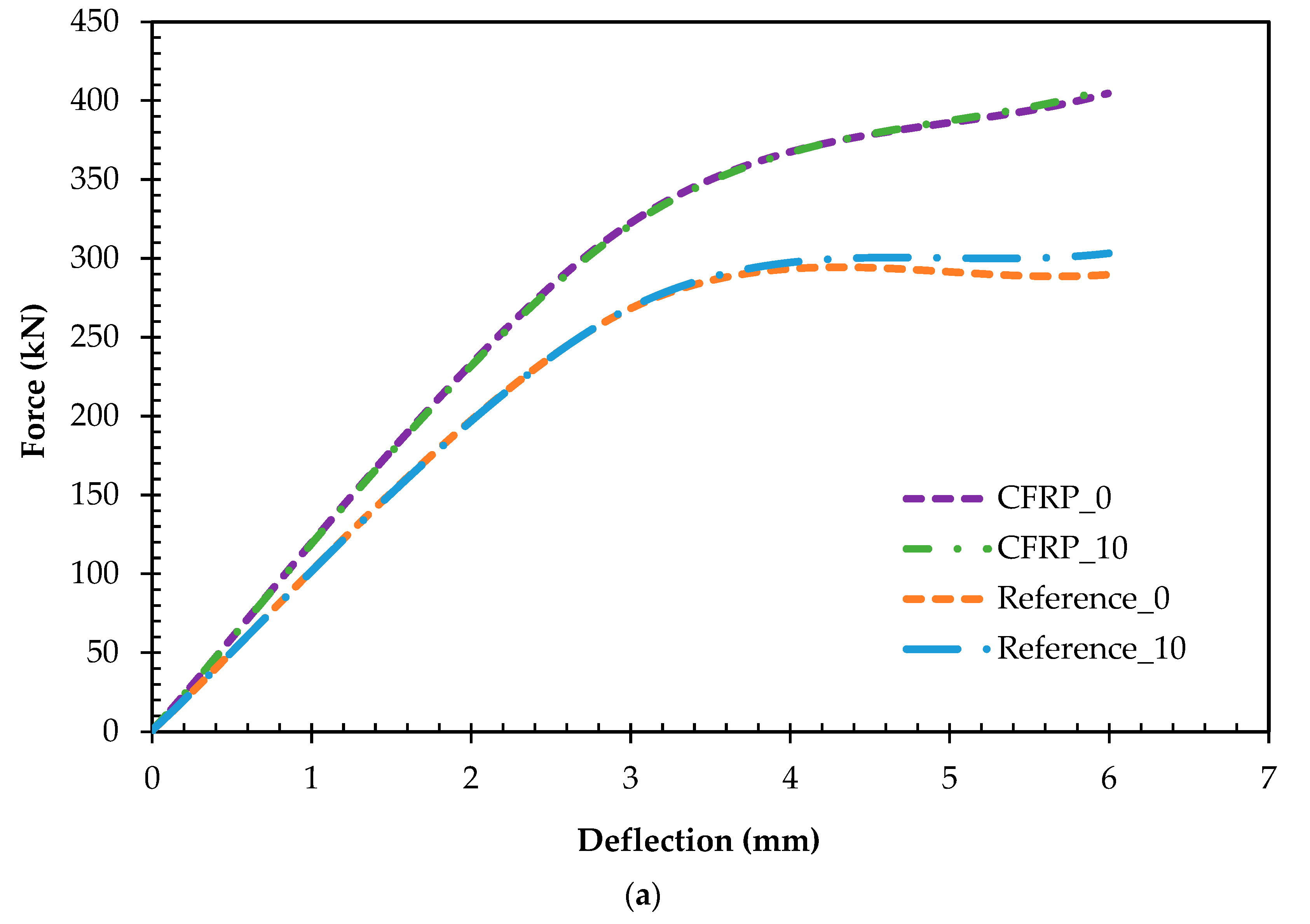
CFRP sheets were used to mitigate the issue of corrosion in box culverts. Figure 9 depicts a comparative analysis of the capacities between the reference model and models incorporating CFRP sheets to mitigate damage caused by corrosion. The reference models, denoted as Reference_0, Reference_5, Reference_10, Reference_15, and Reference_20, respectively, represent varying degrees of damage thicknesses in the slab, ranging from 0 mm to 20 mm. In contrast, the CFRP models, labeled CFRP_0, CFRP_5, CFRP_10, CFRP_15, and CFRP_20, maintain the same damage thickness as the reference models but incorporate CFRP sheets to counteract the effects of corrosion.
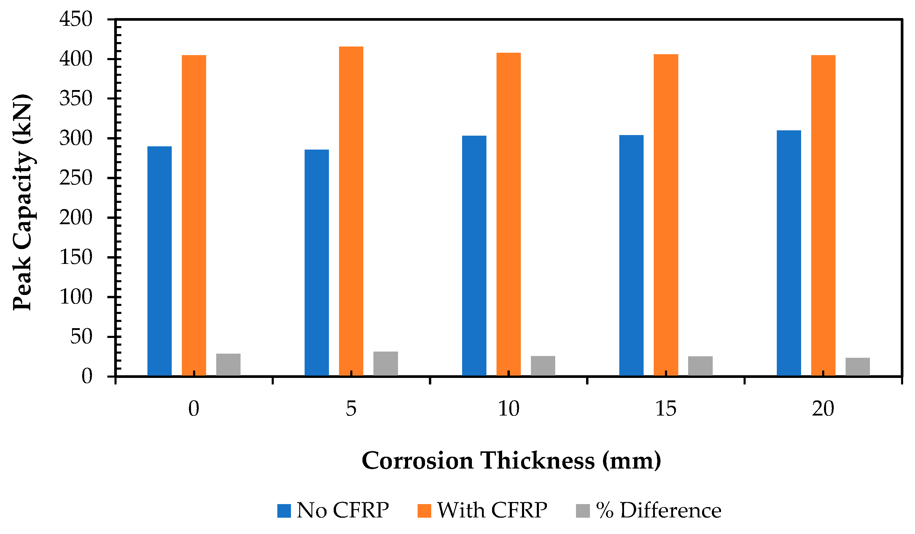
The results shown in Figure 10, indicated by a bar chart comparing the reference and CFRP models, revealed a notable enhancement in the culvert capacity with the incorporation of CFRP sheets. The benefits of integrating CFRP sheets in mitigating corrosion within box culverts are multifaceted. Firstly, CFRP sheets provide a protective layer that shields the underlying structure from corrosive elements, thereby extending the lifespan of the culvert. Secondly, the improved capacity offered by CFRP sheets ensures the structural integrity of the culvert, reducing the risk of failure and associated maintenance costs. Additionally, the use of CFRP sheets can minimize downtime for repair and maintenance, contributing to the uninterrupted functionality and safety of transportation infrastructure. Overall, the application of CFRP sheets illustrated a cost-effective and efficient solution for addressing corrosion-related challenges in box culverts, ultimately enhancing their longevity and performance. It is evident that the addition of CFRP sheets leads to a reduction in damage and a substantial increase in the capacity, with each model experiencing approximately a 25% improvement. Table 7 displays the percentage difference in the capacity, implying the extent to which the capacity enhanced between the models with CFRP sheets installed at the location of corrosion damage and the reference models without CFRP sheets.

3.2. Parametric Study of Using CFRP Stirrups

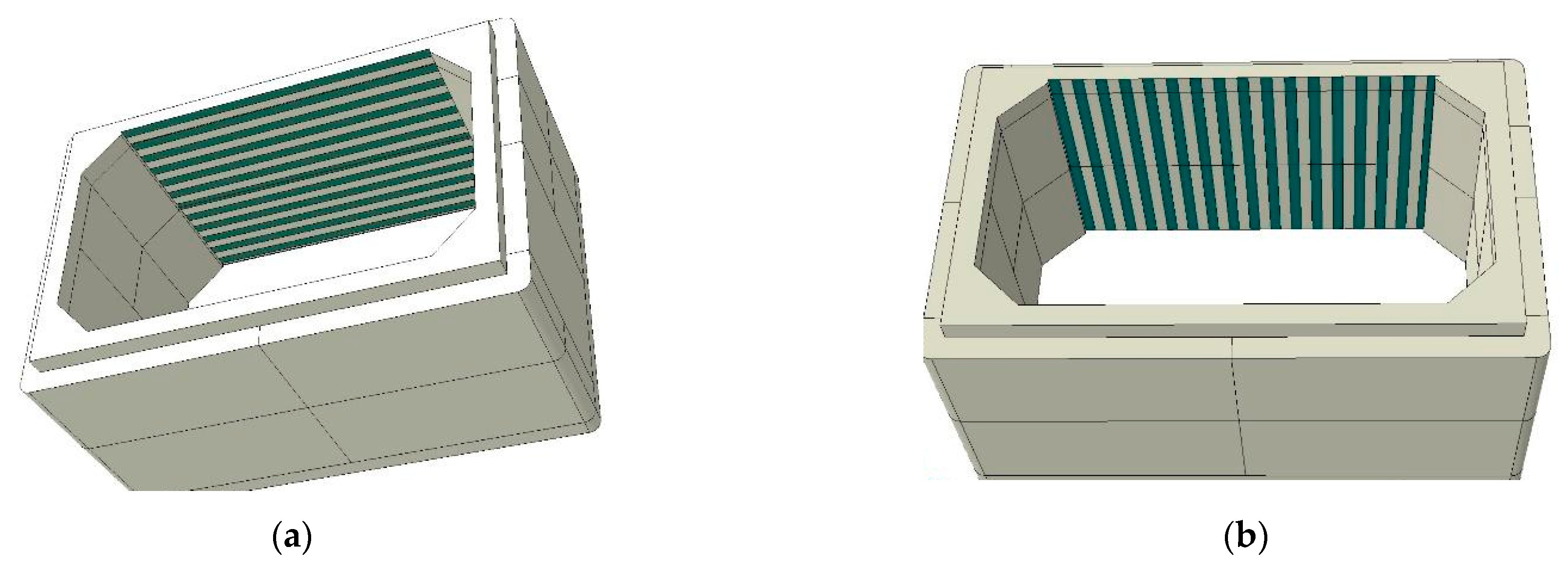
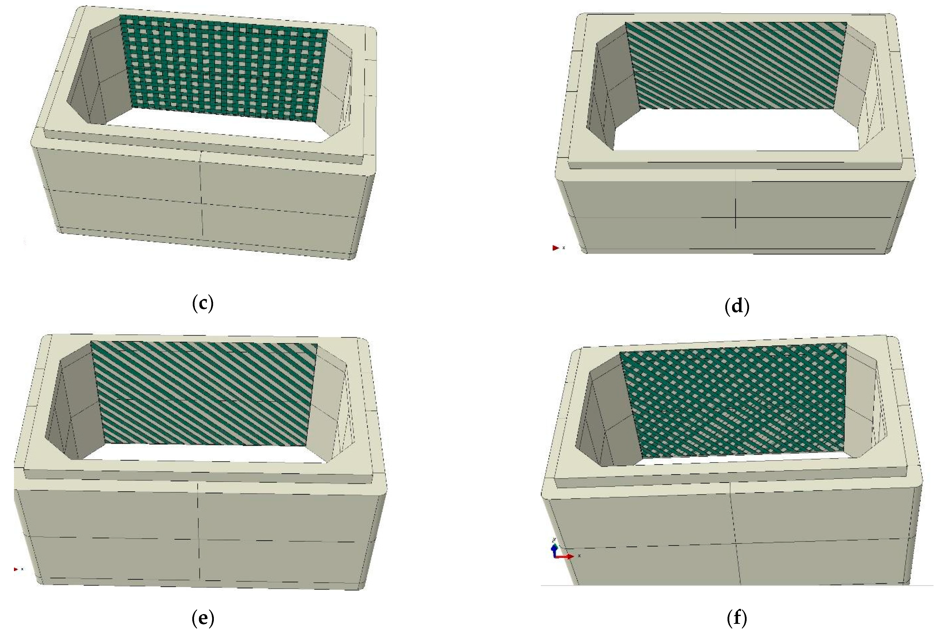
In pursuit of enhancing the design efficiency and cost-effectiveness, a thorough parametric study was undertaken on a reference model featuring 20 mm of slab damage to investigate the impact of CFRP sheets on both the load capacity and damage mitigation of the culvert system. Figure 11 meticulously delineates the various configurations of CFRP stirrups utilized for modeling purposes. To ensure consistency, the width and spacing from edge to edge on each stirrup were maintained at 50 mm and 55 mm, respectively, across all the configurations.
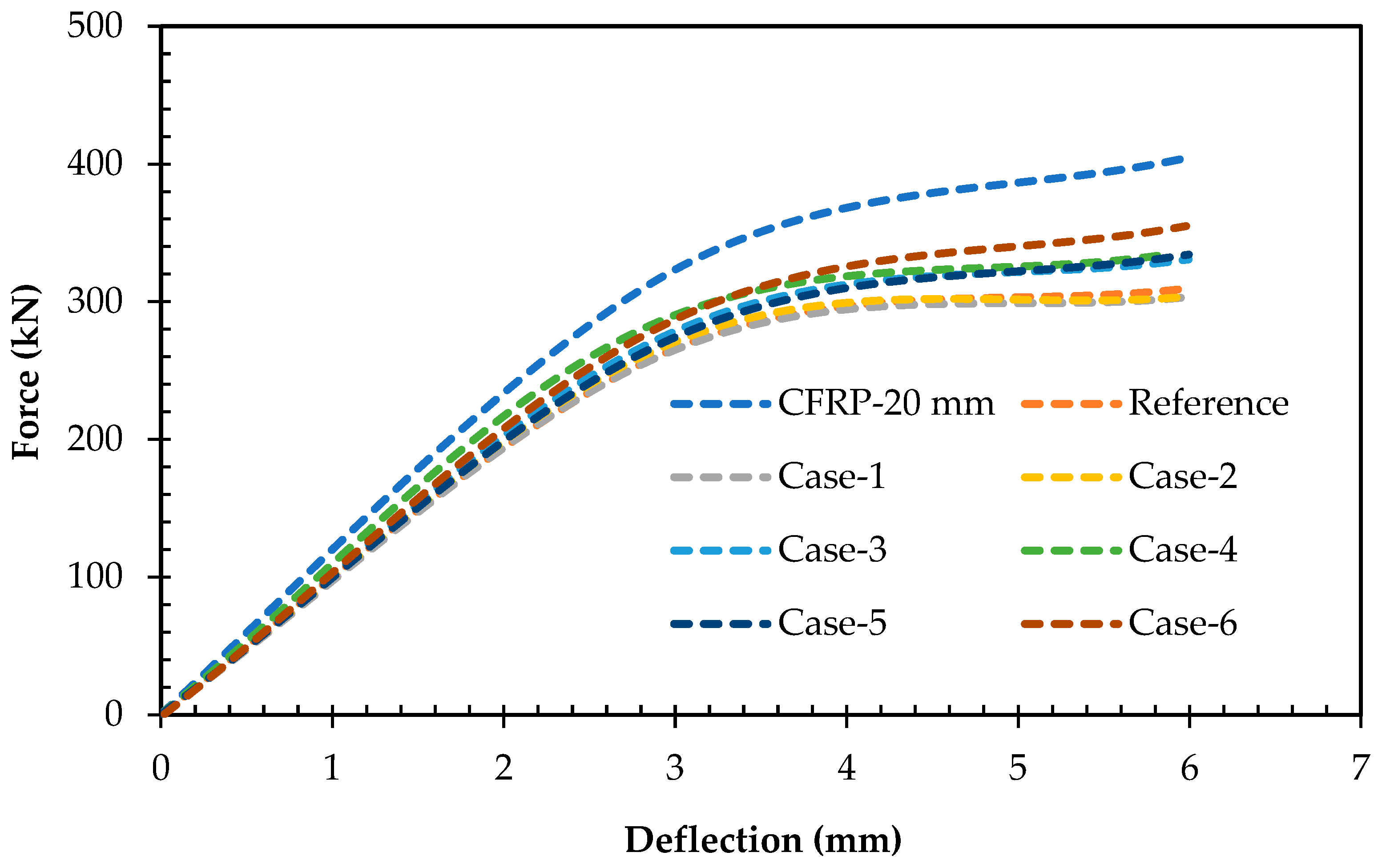
The comparative analysis in Figure 12 presents the outcomes of all the cases against the original model with 20 mm of damage in the culvert slab. Moreover, a model incorporating a full sheet of CFRP (CFRP-20 mm) at the damaged location was included for the comparative assessment, aiming to discern if the effectiveness of CFRP stirrups could match that of the entire sheet.
Upon the evaluation, it became evident that configurations 1 and 2 failed to provide effective solutions for installing CFRP stirrups, exhibiting the comparable damage and reduced capacity akin to the reference model. Similarly, configurations 3, 4, and 5 illustrated marginal improvements over cases 1 and 2 but remained inadequate in withstanding the damage incurred by the culvert slab. Configuration 6 indicated the highest capacity among the studied cases; however, it still revealed a substantial disparity compared to the CFRP-20 mm case. Consequently, it can be deduced that the comprehensive coverage provided by a full sheet of CFRP is imperative for ensuring the proper design and repair of culvert boxes.
An insight into our analysis results is presented to underline the significance of this research. This study emphasizes the crucial role of integrating full CFRP sheets in culvert design and repair efforts. This assertion is bolstered by the displayed increase in the structural capacity and reduction in the damage observed in culverts strengthened with full CFRP sheets compared to alternative methods. Not only do full CFRP sheets offer comprehensive coverage, effectively mitigating damage across the entire slab, but they also bolster the structural integrity, substantially increasing the load capacity and the resilience against damage. Furthermore, by minimizing the need for frequent maintenance and repairs, the utilization of full CFRP sheets promises to reduce overall lifecycle costs and ensure the long-term sustainability of culvert infrastructures. Thus, this study recommends the incorporation of full CFRP sheets as an indispensable strategy for optimizing the culvert design efficiency, longevity, and performance.

4. Conclusions

In conclusion, this study effectively explored and demonstrated the positive impact of CFRP strengthening methods on enhancing the load-carrying capacity of culverts, using robust FEM for insightful design improvements. A representative culvert structure adhering to the ASTM standards was modeled numerically to serve as a reference structure in Abaqus. The reference model was improved utilizing CFRP sheets for enhanced design and strength. This unique application of commonly employed strengthening methods in previous studies was explored specifically for culvert structures. A detailed comparison of load–deflection curves between the reference and CFRP-strengthened models was made to assess their ultimate load-carrying capacities. The study presented the following concluding points.
  • This research revealed the effectiveness of CFRP sheets in mitigating the effects of corrosion, resulting in a noticeable increase in the structural capacity of box culverts. CFRP is a promising solution for the improvement of the service life and strength of corroded box culverts.
  • CFRP strengthening depicted its potential to mitigate the effects of corrosion and enhance the overall performance, with a remarkable 25% increase in the structural capacity of corroded box culverts compared to those without CFRP strengthening.
  • Utilizing a full CFRP sheet emerged as a crucial factor for the efficient design and repair of deteriorated culvert boxes.
Considering the findings of this research, it would be practical to further investigate the applicability of the proposed design-enhancement methods for designing safe and cost-effective culverts by evaluating the effectiveness of wider-span box culverts with exposure to seismic loads in addition to corrosion effects. Furthermore, an experimental study on these models should also be explored to assess the environmental effects of water-induced corrosion on CFRP strengthening methods. The influence of other FRP types on the strengthening of corroded culverts is a crucial topic to explore.

Author Contributions

Conceptualization, H.A.W., A.B. and F.A.; methodology, H.A.W., A.B., F.A. and M.S.; investigation, H.A.W. and A.B.; validation, H.A.W., A.B. and M.S.K.; formal analysis, A.B.; data curation, H.A.W., A.B., F.A. and M.S.; software, H.A.W., A.B. and F.A.; writing—original draft preparation, H.A.W., A.B., F.A. and M.S.; writing—review and editing, H.A.W., A.B. and F.A.; visualization, H.A.W., A.B., F.A., M.S. and M.S.K.; supervision, H.A.W., A.B. and F.A.; project administration, A.B. All authors have read and agreed to the published version of the manuscript.

Funding

This research received no external funding.

Data Availability Statement

The data will be made available on request.

Conflicts of Interest

The authors declare no conflicts of interest.

References

  1. Smart, P.; Herbertson, J.G. Drainage Design; Blackie: Glasgow, UK, 1992; p. 299. [Google Scholar]
  2. McGrath, T.; Moore, I.; Selig, E.; Webb, M.C.; Taleb, B. Recommended Specifications for Large-Span Culverts; NCHRP Report; Transportation Research Board National Research Council 2101 Constitution Avenue: Washington, DC, USA, 2002. [Google Scholar]
  3. AASHTO. AASHTO LRFD Bridge Design Specifications, 9th ed.; American Association of State Highway and Transportation Officials: Washington, DC, USA, 2020; pp. 3–33. [Google Scholar]
  4. Mackie, K.; Stojadinovic, B. Seismic Demands for Performance-Based Design of Bridges; PEER Report 2003-16; Pacific Earthquake Engineering Research Center, University of California: Berkeley, CA, USA, 2003. [Google Scholar]
  5. Miyazaki, Y. Fundamental Study on Seismic Behavior of Hinge Types of Precast Arch Culverts in Culvert Longitudinal Direction. 2019. Available online: https://repository.kulib.kyoto-u.ac.jp/dspace/bitstream/2433/242475/2/dkogk04553.pdf (accessed on 24 August 2023).
  6. Bian, X.; Tang, X.; Shen, W.; Ling, D.; Chen, Y. An Experimental Study on a Culvert Buried in Granular Soil Subjected to Vehicle Loads. Adv. Struct. Eng. 2012, 15, 1031–1040. [Google Scholar] [CrossRef]
  7. Gong, Y.; Ma, Y.; Tan, G.; Bi, H.; Pang, Y.; Ma, C. Experimental Study and Numerical Simulation on Failure Process of Reinforced Concrete Box Culvert. Adv. Civ. Eng. 2020, 2020, 5423706. [Google Scholar] [CrossRef]
  8. Tang, Y.; Bao, Y.; Zheng, Z.; Zhang, J.; Cai, Y. Performance Assessment of Deteriorating Reinforced Concrete Drainage Culverts: A Case Study. Eng. Fail. Anal. 2022, 131, 105845. [Google Scholar] [CrossRef]
  9. Ali, A.M. Manual RC Box Culvert Analysis and Designing. Int. J. Innov. Sci. Res. Technol. 2020, 5, 91–115. [Google Scholar] [CrossRef]
  10. Moradi, M.; Valipour, H.; Foster, S. Reserve of Strength in Inverted U-Shaped RC Culverts: Effect of Backfill on Ultimate Load Capacity and Fatigue Life. J. Bridge Eng. 2015, 21, 04015051. [Google Scholar] [CrossRef]
  11. Maximos, H.; Erdogmus, E.; Tadros, M.K. Fatigue evaluation for reinforced concrete box culverts. ACI Struct. J. 2010, 107, 13–20. Available online: https://experts.nebraska.edu/en/publications/fatigue-evaluation-for-reinforced-concrete-box-culverts (accessed on 24 August 2023).
  12. Garg, A.K.; Abolmaali, A.; Fernandez, R. Experimental Investigation of Shear Capacity of Precast Reinforced Concrete Box Culverts. J. Bridg. Eng. 2007, 12, 511–517. [Google Scholar] [CrossRef]
  13. Gebremedhn, Z.; Qiao, G.; Li, J. Finite Element Modeling and Analysis of Precast Reinforced Concrete U-Shaped Box Culvert Using ABAQUS. Am. J. Civ. Eng. 2018, 6, 162. [Google Scholar] [CrossRef]
  14. Haghani, R.; Yang, J.; Gutierrez, M.; Eamon, C.D.; Volz, J. Fiber Reinforced Polymer Culvert Bridges—A Feasibility Study from Structural and LCC Points of View. Infrastructures 2021, 6, 128. [Google Scholar] [CrossRef]
  15. Hassanli, R.; Youssf, O.; Manalo, A.; Najafgholipour, M.A.; Elchalakani, M.; Castillo, E.d.R.; Lutze, D. An Experimental Study of the Behavior of GFRP-Reinforced Precast Concrete Culverts. J. Compos. Constr. 2022, 26, 04022043. [Google Scholar] [CrossRef]
  16. Vijayan, D.S.; Sivasuriyan, A.; Devarajan, P.; Stefańska, A.; Wodzyński, Ł.; Koda, E. Carbon Fibre-Reinforced Polymer (CFRP) Composites in Civil Engineering Application—A Comprehensive Review. Buildings 2023, 13, 1509. [Google Scholar] [CrossRef]
  17. Bakkour, F.; Tuhta, S.; Günday, F. Determination of Modal Parameters of Reinforced Concrete Box Culvert Retrofitted with GFRP Using Finite Element Method. Int. J. Innov. Eng. Res. Technol. 2022, 9, 1–9. [Google Scholar] [CrossRef]
  18. Sabdono, P.; Sukamta. Reinforcement on existing concrete that has been reinforced with CFRP. Int. Conf. Educ. Soc. Sci. Technol. (ICESST) 2022, 1, 108–121. [Google Scholar] [CrossRef]
  19. Chen, B.-G.; Zheng, J.-J.; Han, J. Experimental Study and Numerical Simulation on Concrete Box Culverts in Trenches. J. Perform. Constr. Facil. 2010, 24, 223–234. [Google Scholar] [CrossRef]
  20. Acharya, R.; Han, J.; Brennan, J.J.; Parsons, R.L.; Khatri, D.K. Structural Response of a Low-Fill Box Culvert under Static and Traffic Loading. J. Perform. Constr. Facil. 2016, 30, 04014184. [Google Scholar] [CrossRef]
  21. Awwad, E.; Mabsout, M.; Sadek, S.; Tarhini, K. Finite Element Analysis of Concrete Box Culverts. In Proceedings of the 8th International Conference on Computing in Civil and Building Engineering, Stanford, CA, USA, 14–16 August 2000; Volume 279, pp. 1051–1053. [Google Scholar] [CrossRef]
  22. Shuhong, W.; Jierula, A.; Wang, P.; Liu, W.; Jie, R. Simulation of force performance of precast rectangular box culvert and its potential failure mode. J. Northeastern Univ. (Nat. Sci.) 2018, 2, 260–265. [Google Scholar]
  23. Uddin, Z.; Waqas, H.A.; Husnain, M.; Ibrahim, M.; Naveed, M.; Zaib, H. Design Optimization of Precast Reinforced Box Culvert with the Application of Finite Element Modeling and Analysis. In Proceedings of the 1st International Conference on Advances in Civil & Environmental Engineering, University of Engineering & Technology, Taxila, Pakistan, 22–23 February 2022. [Google Scholar]
  24. Ozturk, B. Seismic behavior of two monumental buildings in historical Cappadocia region of Turkey. Bull. Earthq. Eng. 2017, 15, 3103–3123. [Google Scholar] [CrossRef]
  25. Moon, J.S.; Kim, D.Y.; Ko, M.S.; Kim, C. Performance of Reinforced Concrete Beams Strengthened by Bidirectional Carbon-Fiber-Reinforced Polymers Based on Numerical Models. Polymers 2023, 15, 1012. [Google Scholar] [CrossRef] [PubMed]
  26. Mahmoud, M.H.; Afefy, H.M.; Kassem, N.M.; Fawzy, T.M. Strengthening of defected beam–column joints using CFRP. J. Adv. Res. 2013, 5, 67–77. [Google Scholar] [CrossRef] [PubMed]
  27. Joyklad, P.; Waqas, H.A.; Hafeez, A.; Ali, N.; Ejaz, A.; Hussain, Q.; Khan, K.; Sangthongtong, A.; Saingam, P. Experimental Investigations of Cement Clay Interlocking Brick Masonry Structures Strengthened with CFRP and Cement-Sand Mortar. Infrastructures 2023, 8, 59. [Google Scholar] [CrossRef]
  28. Tanarslan, H. Behavior of RC beams strengthened with inclined CFRP strips. J. Reinf. Plast. Compos. 2010, 29, 3275–3286. [Google Scholar] [CrossRef]
  29. Singh, J.P.; Kumar, A.; Kumar, A. Application of CFRP in Concrete Culvert Bridges. Lect. Notes Civ. Eng. 2022, 221, 527–537. [Google Scholar] [CrossRef]
  30. ASTM C1577; Standard Specification for Precast Reinforced Concrete Box Sections for Culverts, Storm Drains, and Sewers Designed According to AASHTO LRFD. ASTM International: West Conshohocken, PA, USA, 2005; p. 17.
  31. Smith, M. ABAQUS/Standard UProvidence,. User’s Manual, Version 6.9; Dassault Systèmes Simulia Corp: Providence, RI, USA, 2009. [Google Scholar]
  32. Xiao, Y.; Chen, Z.; Zhou, J.; Leng, Y.; Xia, R. Concrete plastic-damage factor for finite element analysis: Concept, simulation, and experiment. Adv. Mech. Eng. 2017, 9, 1–10. [Google Scholar] [CrossRef]
  33. Ferretti, E. Experimental procedure for verifying strain-softening in concrete. Int. J. Fract. 2004, 126, L27–L34. [Google Scholar] [CrossRef]
  34. Najafgholipour, M.; Dehghan, S.; Dooshabi, A.; Niroomandi, A. Finite element analysis of reinforced concrete beam-column connections with governing joint shear failure mode. Lat. Am. J. Solids Struct. 2017, 14, 1200–1225. [Google Scholar] [CrossRef]
  35. Khan, A.; Ullah, A.; Tariq, M.; Waqas, H.A.; Khan, A.; Khan, J.S. Response of shear critical RC beam under transverse impact using improved linear complementarity. Structures 2023, 54, 1520–1540. [Google Scholar] [CrossRef]
  36. Zhao, K.; Wei, Y.; Yan, S.; Chen, S.; Dong, F. Experimental and analytical investigations on flexural behavior of bamboo beams strengthened with steel bars. Adv. Struct. Eng. 2021, 24, 3338–3356. [Google Scholar] [CrossRef]
  37. Iqbal, M.; Rai, S.; Sadique, M.; Bhargava, P. Numerical simulation of aircraft crash on nuclear containment structure. Nucl. Eng. Des. 2012, 243, 321–335. [Google Scholar] [CrossRef]
  38. Senthil, K.; Rupali, S.; Kaur, N. The Performance of Monolithic Reinforced Concrete Structure Includes Slab, Beam and Column against Blast Load. J. Mater. Eng. Struct. 2018, 5, 137–151. [Google Scholar]
  39. Senthil, K.; Rupali, S.; Satyanarayanan, K.S. Experiments on ductile and non-ductile reinforced concrete frames under static and cyclic loading. J. Coupled Syst. Multiscale Dyn. 2017, 5, 38–50. [Google Scholar] [CrossRef]
  40. Wen, Q.-Q.; Chen, M.-C. Study on the nonlinear performance degradation of reinforced concrete beam under chloride ion corrosion. Eng. Fail. Anal. 2021, 124, 105310. [Google Scholar] [CrossRef]
  41. Sastry, Y.S.; Budarapu, P.R.; Krishna, Y.; Devaraj, S. Studies on ballistic impact of the composite panels. Theor. Appl. Fract. Mech. 2014, 72, 2–12. [Google Scholar] [CrossRef]
  42. Hashin, Z. Failure Criteria for Unidirectional Fiber Composites. J. Appl. Mech. 1980, 47, 329–334. [Google Scholar] [CrossRef]
  43. Zhang, J.; Zhang, X. Simulating low-velocity impact induced delamination in composites by a quasistatic load model with surface-based cohesive contact. Compos. Struct. 2015, 125, 51–57. [Google Scholar] [CrossRef]
  44. Shin, D.; Kim, H.; Lee, J. Numerical analysis of the damage behavior of an aluminum/CFRP hybrid beam under three point bending. Compos. Part B Eng. 2013, 56, 397–407. [Google Scholar] [CrossRef]
  45. Waqas, H.A.; Husnain, A.; Ubaid, H.; Khan, A.P.; Shah, M.; Ilyas, M.; Waseem, M. Assessment of In-fluence of Reinforcement Detailing on Blast Resistance of Reinforced Concrete Beam-column Connections. J. Mater. Eng. Struct. « JMES » 2023, 10, 357–375. Available online: https://revue.ummto.dz/index.php/JMES/article/view/3339 (accessed on 26 August 2023).
  46. Kalfat, R.; Al-Mahaidi, R. Numerical and Experimental Validation of FRP Patch Anchors Used to Improve the Performance of FRP Laminates Bonded to Concrete. J. Compos. Constr. 2014, 18. [Google Scholar] [CrossRef]
  47. ASTM C1433; Standard Specifications for Precast Reinforced Concrete Box Sections for Culverts, Storm Drains, and Sewers. ASTM International: West Conshohocken, PA, USA, 2004; p. 25.
  48. Al-Ameedee, H.S.; Al-Khafaji, H.M. Improving the flexural behavior of RC beams strengthening by near-surface mounting. J. Mech. Behav. Mater. 2022, 31, 701–709. [Google Scholar] [CrossRef]
Figure 1. Flowchart of adopted methodology.
Infrastructures 09 00082 g001
Figure 2. Geometry and reinforcement details of model.
Infrastructures 09 00082 g002
Figure 3. (a) Stress–strain relationship of concrete in compression; (b) compression damage in concrete; (c) stress–strain relationship of concrete in tension; (d) tension damage in concrete.
Infrastructures 09 00082 g003
Figure 4. Stress–strain behavior of reinforcement.
Infrastructures 09 00082 g004
Figure 5. Details of loading mechanism and model constraints.
Infrastructures 09 00082 g005
Figure 6. Culvert model developed based on experimental work of Maximos et al. [11].
Infrastructures 09 00082 g006
Figure 7. (a) Mesh geometry of model; (b) performance of numerical model evaluated using various mesh sizes.
Infrastructures 09 00082 g007
Figure 8. Comparison of crack patterns between FEM and experiments conducted by Maximos et al. [11] (figure used with publisher’s permission).
Infrastructures 09 00082 g008
Figure 9. Comparison of CFRP models and reference models: (a) comparison of CFRP models that have corrosion levels of 0 mm and 10 mm to reference models; (b) comparison of CFRP models that have corrosion levels of 5 mm, 15 mm, and 20 mm to reference models.
Infrastructures 09 00082 g009aInfrastructures 09 00082 g009b
Figure 10. Comparison of capacity between reference model and CFRP.
Infrastructures 09 00082 g010
Figure 11. Configurations of CFRP: (a) Case-1; (b) Case-2; (c) Case-3; (d) Case-4; (e) Case-5; (f) Case-6.
Infrastructures 09 00082 g011aInfrastructures 09 00082 g011b
Figure 12. Capacity and deflection comparison of different CFRP stirrups configurations to reference model that has 20 mm of corrosion damage.
Infrastructures 09 00082 g012
Table 1. Material properties of culvert [32].
MaterialDensity (kg/m3)Young’s
Modulus
(MPa)
Compressive Strength (MPa)Post-Yielding Young’s
Modulus
(MPa)
Tensile
Strength (MPa)
Poisson’s
Ratio
Concrete240032,50026.8-2.40.2
Reinforced steel7850200,00045020,0004500.3
Table 2. CDP model parameters [32].
ParameterValue
Ψ40°
E0.1
σ b 0 σ c 0 1.16
K0.66
μ0.001
Table 3. Elastic properties of CFRP.
Density (t/mm3)E1 (MPa)E2 (MPa)u12G12 (MPa)G13 (MPa)G23 (MPa)
1.56 × 10−9130,00080000.28450045003600
Table 4. Hashin damage defined for CFRP.
Longitudinal Tensile Strength (MPa)Longitudinal Compressive Strength (MPa)Transverse Tensile Strength (MPa)Transverse Compressive Strength (MPa)Longitudinal Shear Strength (MPa)Transverse Shear Strength (MPa)
22002200611308540
Table 5. Hashin damage evolution (energy) for CFRP.
Longitudinal Tensile Fraction Energy (mJ/mm2)Longitudinal Compressive Fraction Energy (mJ/mm2)Transverse Tensile Fraction Energy (mJ/mm2)Transverse Compressive Fraction Energy (mJ/mm2)
70700.250.25
Table 6. Results of model’s calibration.
Mesh Size (mm)Displacement
(mm)
Force
(t)
ConcreteSteel
20204.523.9
50504.524.0
1001003.4527
200200535
Chosen mesh sizeFor both steel and concrete, a mesh size of 100 mm was utilizedPercentage error in numerical analysis results10
Table 7. Results of CFRP and reference models with percentage differences.
Corrosion Damage (mm)Ultimate Capacity, Pu (kN)Percentage Difference
ReferenceCFRP
0289.66404.6428.42
5285.53415.6731.31
10303.22407.6125.61
15303.71405.7225.14
20309.86404.7823.45
Disclaimer/Publisher’s Note: The statements, opinions and data contained in all publications are solely those of the individual author(s) and contributor(s) and not of MDPI and/or the editor(s). MDPI and/or the editor(s) disclaim responsibility for any injury to people or property resulting from any ideas, methods, instructions or products referred to in the content.