Article

Dynamic Soil Structure Interaction of a High-Rise Building Resting over a Finned Pile Mat

by
Pankaj Bariker
and
Sreevalsa Kolathayar
*
Department of Civil Engineering, National Institute of Technology Karnataka, Surathkal, Mangaluru 575025, India
*
Author to whom correspondence should be addressed.
Infrastructures 2022, 7(10), 142; https://doi.org/10.3390/infrastructures7100142
Submission received: 19 September 2022 / Revised: 13 October 2022 / Accepted: 17 October 2022 / Published: 19 October 2022
(This article belongs to the Special Issue Advances in Structural Dynamics and Earthquake Engineering)

Abstract

:
High-rise building safety is generally supported by pile-mat systems. They must be sturdy enough to withstand potential lateral loads brought on by earthquakes, wind, dredging, and machine vibrations, in addition to increased axial loads. An innovative piled-mat foundation system is required to deal with these impacts because standard pile foundation systems only have lateral capacities that are 10% of their axial capacities. This study aims to reduce the damage caused by seismic impacts on high-rise buildings using shear walls supported by piled mats, thereby minimizing vibrations within the structure. Compared with conventional pile systems, the finned-pile foundation is a proven method that can withstand a 65% to 80% higher lateral load; hence, a series of SSI analyses were performed on a 25-story high-rise building, with the shear wall resting on a finned-pile mat (FP-Mat), under a far-field earthquake excitation, using ABAQUS software. The seismic responses were studied by performing a time–history analysis on the FP-Mat, with varying fin-lengths (Lf) of 0.2Lp, 0.4Lp, 0.6Lp, and 0.8Lp, which was compared with an analysis of a conventional piled-mat (RP-Mat). The seismic responses for RP-Mat and FP-Mats were studied with peak-acceleration, maximum horizontal displacement, and inter-story drifts acting as the damage parameters. The provision of FP-Mats significantly reduced the vibrations and seismic effects on the building, and as the fin-length increased, the vibrations and seismic effects reduced further. The drifting bound was also reduced as the fin-length increased. The optimum fin-length for FP-Mats is suggested to be 0.6Lp in terms of seismic performance and construction efficiency. This study helps one understand the seismic behaviors of high-rise buildings resting on finned pile mats.

1. Introduction

The majority of constructed multi-story buildings have a significant design margin to allow for the inclusion of sensible amenities and equipment. Most of the earlier literature treats a building’s base as rigid when conducting a seismic response study. The amplification and de-amplification of vibrations depends on the type of structure and the type of soil over which it is established. When performing a seismic–response analysis of a rigid base of a high-rise building, considering an unamplified time history would underestimate the level of vibrations; therefore, it is advantageous to consider the interactions between the soil, pile, and structure when studying the response of multi-story structures to seismic disturbances [1,2]. The majority of internal stresses in the system exchange are due to the fact that the soil stiffness deteriorates due to seismic excitation, where some of the supplied energy is lost, owing to soil damping [3] and changes in input excitation in the system [4].
The dynamic loads, which emerge due to the operation of the machine and earthquake, have a detrimental effect on the structure’s performance, thereby amplifying the damage parameters (i.e., horizontal displacement and inter-story drifts) [5,6,7]. The seismic response of high-rise buildings with shear walls are thus of higher importance, and their performance is different to those without shear walls [8]; hence, suitable measures should be taken to reduce the detrimental effects of an earthquake on high-rise buildings.
Since lateral resistance is of higher concern when dealing with the effects of an earthquake on a structure, it is responsible for causing more intense levels of damage; hence, the sub-structure of a multi-story building must be innovative enough to resist these detrimental effects, which are caused by high-intensity vibrations. From the recent research on finned piles, it has been noted that they provide higher levels of lateral resistance than conventional piles in the case of offshore foundations [9,10] and onshore foundations [11,12]. The finned piles also work effectively under a combined load, and fin shape greatly influences the behavior of the pile [12,13]. The level of lateral resistance in finned piles is largely influenced by fin-length, rather than fin-width [11,12,14] or fin-orientation [15,16]. Moreover, finned-piles with smaller diameters are capable of withstanding lateral loads that are equivalent to that of regular piles with larger diameters [14]. The finned piles with rectangular fins provide greater levels of resistance than triangular fins [11,12,16,17]. Finned piles not only increase lateral resistance, but they also decrease lateral deformation; thus, both the criteria (load and serviceability) of the limit state design, as per IS:456-2000 [18], are satisfied [19].
According to previous research, a finned pile foundation is one of the proven innovative techniques [19] that aids the resistance of the static latera load [9,10,11,12,14,15,16,20,21,22], cyclic loads [23], and combined loads [13]; hence, the present study aims to quantify the seismic response of a 25-story building, with a shear-walls facility, supported with a conventionally piled-raft (RP-Mat). This study also attempted to reduce the seismic response of a similar building with the finned-pile mat system (FP-Mat), while numerically considering the soil–pile structure interaction by creating a SSI model using ABAQUS-CAE software.

2. Materials and Methods

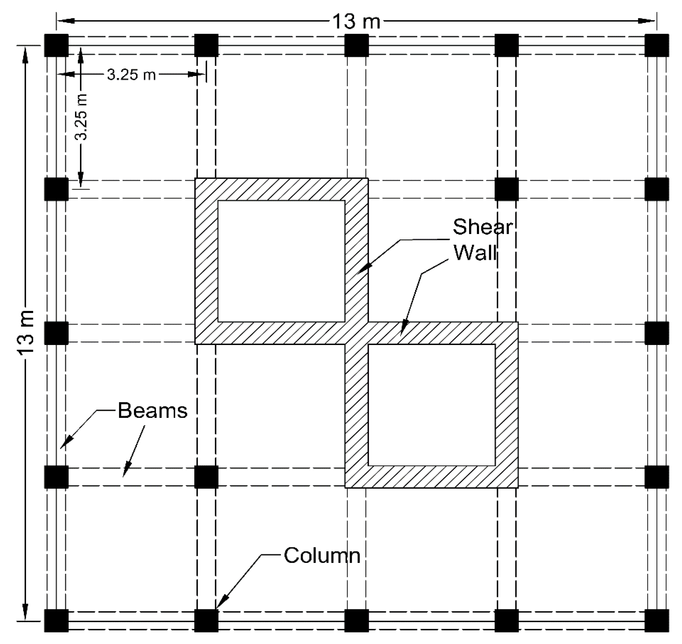
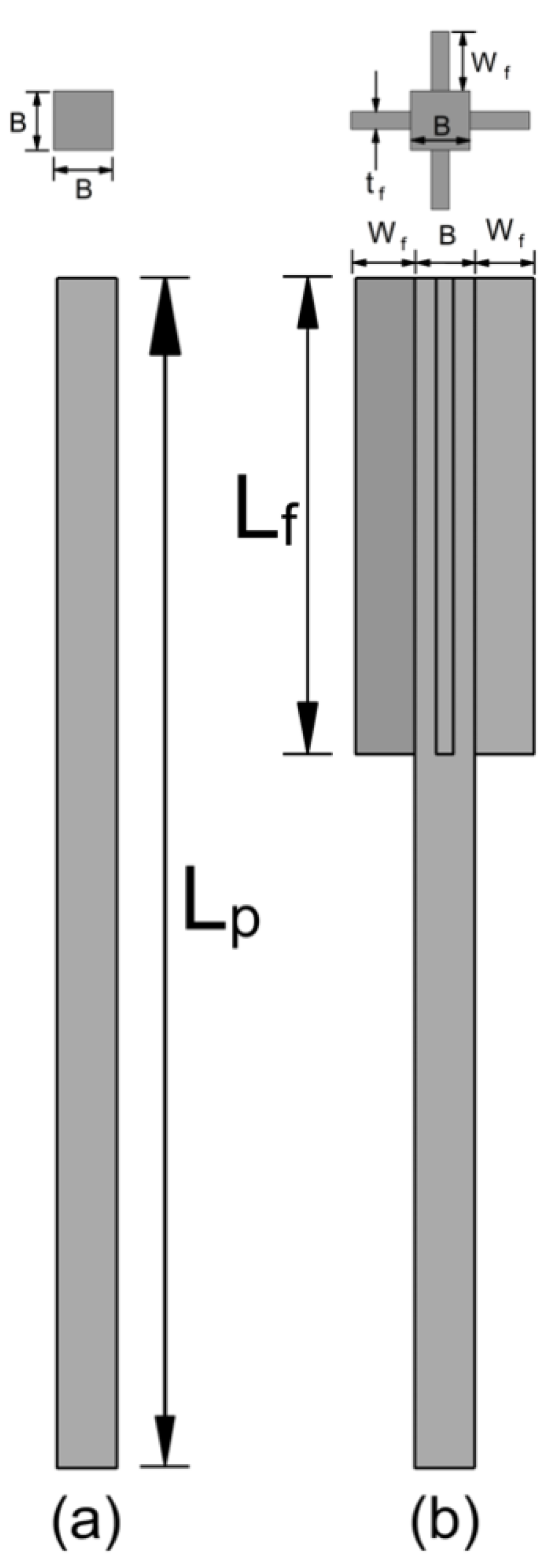
2.1. Structural Design

The structural analysis of the 25-story building was performed using ETABS software [24], which was confined to IS-456: 2000 [18] for the concrete frame design, with the plan details shown in Figure 1. The dynamic analysis was performed as per IS: 1893-2016 [25], with the time–history analysis using El-Centro earthquake data, which was collected from the PEER Earthquake database [26], with a magnitude of (Mw) of 6.9, a time of 53.74 s, and a peak acceleration of 0.349 g, as shown in Figure 2.
All structural sections were made from M-35 grade concrete, with a compressive strength of (fck) 35 MPa. The Young’s modulus of the concrete was Ec = 5000 (fck)0.5 (29,580 MPa), it had a unit weight of 25 kN/m3, and a steel rebar made from Fe-500 grade steel, with a yield strength (fy) of 500 MPa; these factors were used for the analysis, and the properties were defined as per [18,24]. The damping of 5%, which occurred within the structural members, was considered for the dynamic analysis. The dimensions of all the structural elements are listed in Table 1 and Figure 3. The fundamental frequency and total mass of the fixed base building were found to be 0.547 Hz and 33.45 t, respectively. From the results of the dynamic structural design, the building period was found to be 1.827 s, and the effective mass ratios for the first three modes, and for the end of all modes, were found to be 0.7195 and 0.9187, respectively.
With the base reactions obtained from the structural analysis, which was conducted using the ETABS software, the foundation system was designed using SAFE software. The details of the piled-raft foundation system were finalized (i.e., safe against, one-way-shear, two-way (punching) shear criteria as per IS: 456-2000) [18]. The design details of the sub-structure (i.e., a piled-raft foundation in which 2 m of thick raft, with 20 m × 20 m plan dimensions, supported over 81 square piles; its cross-section measured at 0.25 m2 (9 × 9 piled configuration), and it was 30 m in length (Lp), with pile spacings (S) of 2.25 m) is shown in Figure 3.

2.2. Material Properties

For this study on seismic soil interactions, the soil was collected from one of the sites of the Mangalore Special Economic Zone (MSEZ), its soil properties were tested as per SP-36:Part-1, 1987 [27], and the soil was classified as low compressible silt—poorly graded sand (ML-SP), as per ASTM D-2487-17e1, 2017 [28]. The high-rise (25-story) building was composed of M35 grade concrete, as per IS: 456-2000 [18], and its sub-structure (i.e., the piled-mat) was thought to be embedded in the silt-soil. The properties of the soil and the structural elements of the M35 concrete were the same as those used in the structural design; those used in the present SSI analysis are listed in Table 2. A dilation angle of 1° was used to avoid divergence in the FEM analysis. The structural elements are defined as visco-elastic materials. The structural damping value adopted for the analysis was 5%, and this was incorporated in the form of Rayleigh coefficients, α = 0.2015 and β = 0.012, which were based on the modal frequencies. The results were validated well using the work of Zhang et al. [8]; the maximum lateral deformation for the fixed-base structure and flexible base structure were compared with the present study, as shown in Figure 4, and good agreement was found between both the models.

2.3. Three-Dimensional FEM Modeling

The ABAQUS-CAE software package [29] was used to study the dynamic soil–structure interaction in which the Rayleigh coefficients (α and β) were calculated by considering the frequency-dependent damping that forms the different modes comprising the soil-foundation [30]. The mass damping factor (α) and stiffness damping factor (β) utilized in the study were 0.758 and 0.012, respectively. Each of the structural elements, detailed above in Table 1, were modeled as separate parts and assembled in their respective positions. They were later merged to form the super-structural part of the multi-story building, as shown in Figure 3. The piled-raft is modeled as a single part by defining the raft as 2 m thick and extruding the 30 m length piles beneath it. The cut geometry command was used to cut the unwanted part of the soil (i.e., to excavate the soil portion so that it could be occupied by the pile-raft).
To examine the soil–structure interaction, surface-to-surface contact was used to ascertain the interactions between each pile, mat, and the neighboring soil. In cases where the soil was the softer material between the soil and the structure, the soil-surface was called the slave-surface. Moreover, the pile or mat was called the master-surface for the soil–pile and soil–mat interaction cases, respectively. Tangential contact (friction contact) was defined using a frictional behavior that was formulated using contact–pressure data to simulate the Mohr–Coulomb failure criteria, as shown in Equation (1) [11,14,31]. The interaction reduction factor (Rinter) of 0.75 was used in most of the geotechnical simulations [32,33] in order to reduce the interface’s shear strength, which is dependent on the roughness of the pile, and the pile construction method used in the field [34]. Normal contact was defined as hard so that the pile did not puncture the soil stratum.
Shear strength inter = R i n t e r Shear strength S o i l
Mesh sensitivity analysis was performed to reduce the computational time of the analysis. For meshing, various element distributions, which were designated as very coarse, coarse, medium, fine, very fine, and refined, were used generating 27,628, 68,248, 134,462, 268,612, 352,840, and 153,572, elements respectively. Considering the computational time and the accuracy of the results, the refined element distribution was found to be the most efficient for meshing purposes when compared to the other element distributions; hence, the refined element distribution was adopted for model meshing. Indeed, finer meshing was used near points where large amounts of stress were concentrated, and coarser meshing were used in places that were further away from these highly concentrated areas of stress. The soil and structural elements were defined as solid parts, and they were coupled with C3D8R elements in order to avoid reflecting earthquake vibrations back into the model. The far-field soil was modelled using the infinite CIN3D8 elements that were used to absorb the vibrations from the unbound soil, as shown in Figure 5.
Boundary conditions were set in order to avoid a translation, in all three directions, of the soil base in the initial step (UX = UY = UZ = 0). Since earthquake loading was applied in the x-direction, a translation in the x-direction (UX) was allowed when performing the time–history analysis during the earthquake step. Moreover, the sides of the soil model were restricted from being translated in both the x and y directions (UX = UY = 0) for both steps. The complete three-dimensional model used for the time–history analysis is shown in Figure 5.

3. Numerical Analysis Program

A soil structure interaction (SSI) is defined as an exchange of internal stresses between the soil and the structure that is developed in the system during an earthquake. It also alters the dynamic response of the soil–structure system as soil stiffness degrades during an earthquake. The provision of SSIs is a proven technique with which to predict the structure’s actual response. Most previously published research [35,36,37,38,39,40] concluded that the pile-raft technique is an alternative method to the examination of SSIs, with regard to overcoming potential disastrous effects on buildings. This is because post-earthquake effects on buildings cannot be nullified with any of the remedial foundation techniques, but they can be maximally reduced in order to reduce the detrimental effects of earthquakes on high-rise buildings.
The use of finned piles is an innovative technique that has an advantageous lateral response over regular piles in a system. During the search for such an innovative approach for use as a remedial measure, a series of time–history analyses were performed on a 25-story building resting over a finned pile-mat system. The response of the finned pile-mat system was compared with the regular pile-raft system. The schematic view of the regular piled-raft and finned pile raft is shown in Figure 6. The size of each pile used in the study was calculated as B × B (0.5 m × 0.5 m), and their lengths were calculated as Lp (30 m). In addition, finned piles, with fin widths (Wf), assumed to have the same as pile width (B) i.e., 0.5 m, fin thicknesses tf (0.15 m), and fin-lengths (Lf) as those in regular pile.
The SSI numerical analyses program that was performed using ABAQUS is shown in Table 3 below. The series I analysis was performed with a RP-Mat (regular pile-mat), and the response of the RP-Mat will serve as a reference for comparison. Series II analyses were performed with a FP-Mat (finned pile-mat), with varying fin-lengths (Lf) of 0.2Lp, 0.4Lp, 0.6Lp, and 0.8Lp; the responses from these analyses will provide the data to decide the effectiveness of the FP-Mat under earthquake loading conditions. The responses are recorded in terms of the seismic damage parameters, which are peak acceleration, peak displacement, inter-story drift, and drifting bounds. The story-drift [25] and inter-story drift [8] are calculated as shown in Equations (2) and (3) below. The inter-story drift ratio plays important role in deciding the detrimental effects of an earthquake on a building, as it defines the average rotation angle between the column and beam.
S t o r e y   d r i f t = u i + 1 u i
I n t e r   s t o r e y   d r i f t = S t o r e y   d r i f t S t o r e y   H e i g h t × 100

4. Analysis of the Regular Pile-Mat

To study the response of the 25-story building that was supported using a RP-Mat, an analysis was performed using a 3D FEM model of a RP-Mat; the details for which are mentioned in series I of Table 3, and they are shown in Figure 4. The response of the model was aggregated in the form of time–history plots (i.e., acceleration variation and inter-story drift experienced by various floor levels of the building). The acceleration (time–history) plots are shown in Figure 6; it was observed that the building experienced greater acceleration for higher floor levels, with its peak acceleration (ap) varying between 0.012 g at the base, to 0.25 g (71.6% of the applied earthquake) on the top floor (25th floor) of the building as shown in Figure 7.
The variation of the inter-story drift is shown in Figure 8; it was observed that the inter-story drift increased as we proceeded towards higher floors, which is due to the higher vibrations experienced by the building, as shown in Figure 7. Moreover, the building experienced a higher inter-story drift, corresponding to 6.82 s, as the floor level increased, and the maximum story drift was found to be about 0.0084 m (forming an inter-story drift of 0.28%), which is well within the permissible story drift of 0.012 m, as per IS: 1983 (2016) [25]; hence, to study the effect of the FP-Mat in reducing the seismic response of a building, we proceeded with the available model to study improvements that could be made.

5. Analysis of the Finned Pile-Mat

To study the effect of the finned pile-mat (FP-Mat) in terms of reducing the seismic response of a multi-story structure, a series of analyses were performed on FP-Mats of varying fin-lengths (Lf/Lp), which were 0.2, 0.4, 0.6, and 0.8, respectively. The 3D models of the FP-Mats utilized in this study are shown in Figure 9 below. The time–history analyses were performed on FP-Mats that were similar to RP-Mats, using the El-Centro earthquake data (Figure 2).

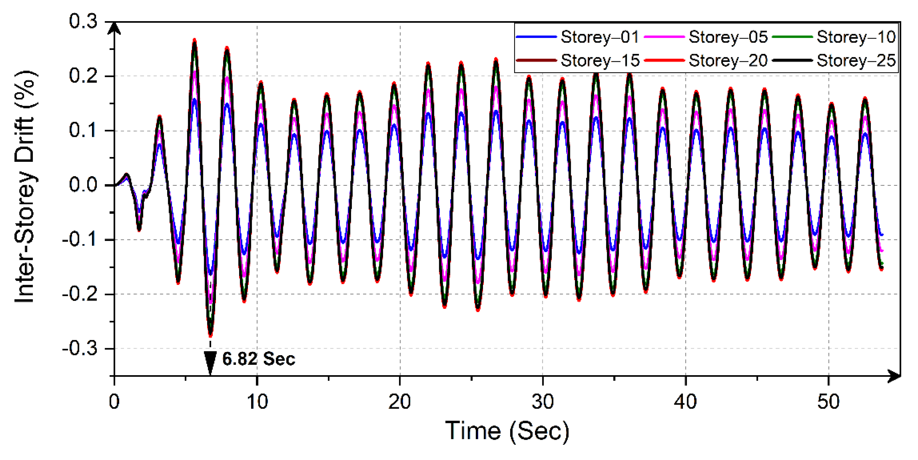
5.1. Time–History Plots

The time–history plots (acceleration and inter-story drift) of the various floor levels of the 25-story building, which was supported by the FP-Mats mentioned above, are shown in Figure 10 and Figure 11, respectively. The provision of an FP-Mat under a multi-story building drastically enhances seismic behavior, and thus, the peak acceleration and inter-story drift of the top floor were reduced by 99.99%, in comparison with the RP-Mat, thereby reducing the effects of detrimental vibrations on the building.
Moreover, a stiffer response was observed in the building supported by the FP-Mats as they had greater fin-lengths. Due to the increased flexural stiffness of the piled-mat system, greater passive resistance was developed against the applied seismic loading. The peak inter-story drift for buildings on FP-Mats occurs at the time points 5.67, 11.14, 5.66, and 11.16 s, with fin-lengths (Lf) of 0.2Lp, 0.4Lp, 0.6Lp, and 0.8Lp, respectively, as shown in Figure 10 below.

5.2. Effect of Fin-Length on the Seismic Response of the Structure

To study the effect of the fin-length (Lf) of finned piles in FP-Mats on a high-rise building, a path was created from the base floor to the top story of the building in the visualization module of the ABAQUS; hence, the output in the form of peak acceleration, peak horizontal displacement, and inter-story drift, for the defined path, is extracted for the natural period of the piled-mat system, as shown in Figure 11.

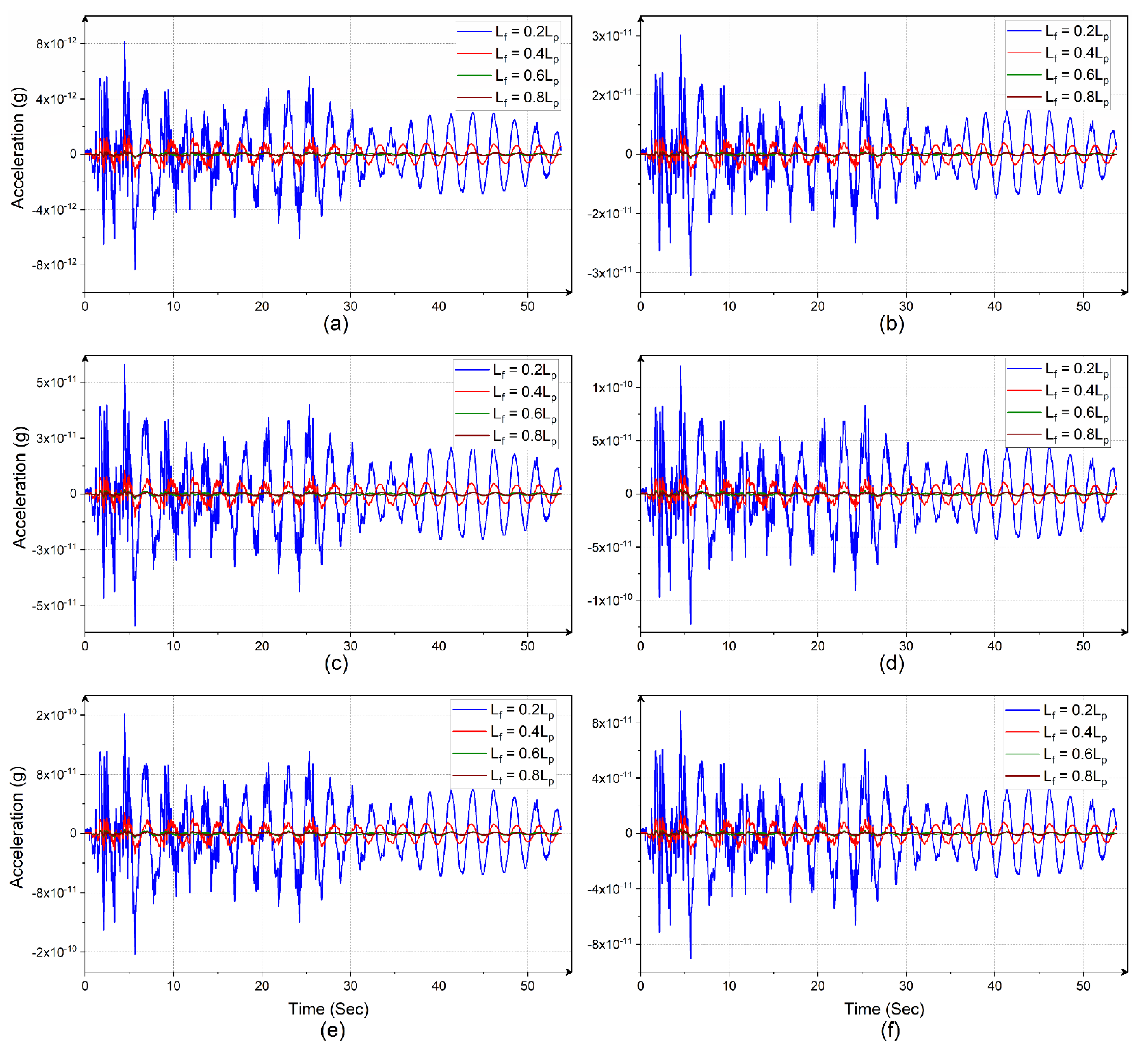
5.2.1. Variation in Peak Acceleration

The variation in peak acceleration for all floor levels was plotted for all considered FP-Mats of various fin-lengths, as shown in Figure 12. It was observed that the response of the building was stiffer for all the piled-mats after Story-10 (this finding is also shown in Figure 10, as the time–history plot of the inter-story drift was somewhat similar for all floor-levels above Story-10). Figure 12 shows that the peak acceleration experienced by the top floors ranges between 15 to 20 times that of the base floor. Moreover, the reduction in peak acceleration, compared with the RP-Mat, was somewhat diminished by the provision of the FP-Mat.

5.2.2. Variation in Peak Horizontal Displacement

The variation in the peak horizontal displacement (u) of the high-rise building for all floor levels, using various piled mats, is shown in Figure 13. It was observed that the horizontal displacement on the top story was 20.66 times that of the base floor when using the RP-Mat, and when using the FP-Mat, the horizontal displacement is 16 to 18 times that of the base floor. Moreover, the horizontal displacement readings for the FP-Mats with fin-lengths (Lf) of 0.6Lp and 0.8Lp were found to be identical, thus making the structure lesser susceptible to vibrations. Considering the seismic performance and economical construction, 0.6Lp may be considered the optimum fin-length for reducing the seismic response.

5.2.3. Variation in Inter-Story Drift

The variation in the inter-story drift for multi-story buildings resting on various FP-Mats and RP-Mats is shown in Figure 14. It was observed that buildings resting on RP-Mats show softened inter-story drift variations, and FP-Mats show stiffer responses than RP-Mats. In terms of FP-Mats, an increase in the fin-length (Lf) increases the stiffening behavior of the building. Stiffer behavior means the same horizontal displacement for two consecutive floors (i.e., inter-story drift). To ensure that the building exhibited stiffer behavior, the story numbers 16, 13, 11, and 9, corresponded with fin-lengths (Lf) of 0.2Lp, 0.4Lp, 0.6Lp, and 0.8Lp, respectively. The lower the inter-story drift, the less damage caused to the building due to seismic activities. As the buildings supported by FP-Mats experience fewer vibrations, displacements, and inert-story drifts, FP-Mats are more advantageous for high-rise buildings than RP-Mats. Moreover, the difference between the maximum and minimum inter-story drifts for a piled-mat system was reduced by using varying fin lengths. The drifting bounds of the FP-Mat system were reduced by increasing the fin-lengths (i.e., the difference between the maximum and minimum inter-story drift was found to be 0.115% for the RP-Mat, whereas for FP-Mats with fin-lengths of 0.2Lp, 0.4Lp, 0.6Lp, and 0.8Lp, the differences were 6.57 × 10⁻¹¹%, 1.23 × 10⁻¹¹%, 3.0 × 10⁻¹²%, and 2.6 × 10⁻¹²%, respectively). Hence, as the fin-length increased, the average rotation between beam and column within the same story was found to be drastically reduced, thus leading to the formulation of a sustainable design.

6. Conclusions

In the present study, a novel attempt was made to quantify the seismic response of piled-mats (RP-Mats) by numerically incorporating the SSI. Moreover, to reduce the detrimental effects on high-rise buildings due to earthquakes, finned-pile mats (FP-Mats) of various fin lengths were adopted. After performing a series of numerical SSI simulations on the high-rise building with 25-stories, using a far-field time history with the El-Centro earthquake data, the following conclusions were made.
  • The maximum peak acceleration and maximum horizontal displacement of the high-rise building supported by piled mats does not drastically increase as we move towards the top story. Instead, it shows stiffer behavior in a particular story (Story-10 in the present study), and variation after that remains almost linear.
  • The provision of fins in the piled mats drastically reduces detrimental vibrations due to earthquakes. Finned piles, with a fin-length (Lf) of just 0.2Lp, can reduce the seismic response of high-rise buildings by more than 98%.
  • The fin-length (Lf) has a high level of influence over the effect of the seismic response, (i.e., regarding FP-Mats, as the fin-lengths increase, the variation between inter-story drift readings remains constant (i.e., stiffer behavior) in subsequent stories). It is responsible for reducing story displacements due to seismic loading.
  • FP-Mats with fin-lengths (Lf) of 0.6Lp and 0.8Lp showed nearly identical horizontal displacement variation; hence, considering the seismic performance and economical construction, 0.6Lp may be considered the optimum fin-length for reducing the seismic response.
  • Compared with the RP-Mat, the using FP-Mats during the construction of high-rise buildings can reduce horizontal displacement by 1.7 × 10⁹, 8.2 × 10⁹, 4.3 × 10¹⁰, and 5.5 × 10¹⁰ times for FP-Mats with fin-lengths of 0.2Lp, 0.4Lp, 0.6Lp, and 0.8Lp, respectively.
  • The drifting bounds of the FP-Mat system were reduced by increasing the fin-lengths (i.e., the difference between the maximum and minimum inter-story drift was found to be 0.115% for the RP-Mats, and for FP-Mats with fin-lengths of 0.2Lp, 0.4Lp, 0.6Lp, and 0.8Lp, the differences were 6.57 × 10⁻¹¹%, 1.23 × 10⁻¹¹%, 3.0 × 10⁻¹²%, and 2.6 × 10⁻¹²%, respectively). Hence, this drastically reduces the average rotation between the beam and column within same story.

Author Contributions

Conceptualization, P.B. and S.K.; methodology, P.B. and S.K.; software, P.B.; validation, P.B.; formal analysis, P.B.; investigation, P.B.; resources, S.K. and P.B.; data curation, P.B.; writing—original draft preparation, P.B.; writing—review and editing, S.K.; visualization, P.B.; supervision, S.K.; project administration, S.K.; funding acquisition, S.K. All authors have read and agreed to the published version of the manuscript.

Funding

Funding received from the IMPRINT-2 program of DST/SERB with MHRD for the project titled “Impounding of River floodwaters along Dakshina Kannada Coast: A sustainable strategy for water resource development” (IMP/2018/001298).

Data Availability Statement

All data, models, and codes generated or used during the study appear in the submitted article.

Acknowledgments

The authors would like to acknowledge the funding received from the IMPRINT-2 program of DST/SERB with MHRD for the project titled “Impounding of River floodwaters along Dakshina Kannada Coast: A sustainable strategy for water resource development” (IMP/2018/001298).

Conflicts of Interest

On behalf of all authors, the corresponding author states that there is no conflict of interest.

References

  1. Kramer, S.L. Geotechnical Earthquake Engineering; Pearson Education India: Noida, India, 1996. [Google Scholar]
  2. Fatahi, B.; Tabatabaiefar, H.R.; Samali, B. Performance Based Assessment of Dynamic Soil-Structure Interaction Effects on Seismic Response of Building Frames. In GeoRisk 2011; American Society of Civil Engineers: Reston, VA, USA, 2011; pp. 344–351. [Google Scholar] [CrossRef]
  3. Wolf, J.P.; Obernhuber, P. Non-linear soil-structure-interaction analysis using dynamic stiffness or flexibility of soil in the time domain. Earthq. Eng. Struct. Dyn. 1985, 13, 195–212. [Google Scholar] [CrossRef]
  4. Anand, V.; Satish Kumar, S.R. Seismic Soil-structure Interaction: A State-of-the-Art Review. Structures 2018, 16, 317–326. [Google Scholar] [CrossRef]
  5. Guin, J.; Banerjee, P.K. Coupled Soil-Pile-Structure Interaction Analysis under Seismic Excitation. J. Struct. Eng. 1998, 124, 434–444. [Google Scholar] [CrossRef]
  6. Tabatabaiefar, H.R. Determining Seismic Response of Mid-Rise Building Frames Considering Dynamic Soil-Structure Interaction. Ph.D. Thesis, University of Technology Sydney, Sydney, Australia, 2012. [Google Scholar]
  7. Tabatabaiefar, H.R.; Clifton, T. Significance of Considering Soil-Structure Interaction Effects on Seismic Design of Unbraced Building Frames Resting on Soft Soils. Aust. Geomech. J. 2016, 51, 55–64. [Google Scholar]
  8. Zhang, X.; Far, H. Effects of dynamic soil-structure interaction on seismic behaviour of high-rise buildings. Bull. Earthq. Eng. 2022, 20, 3443–3467. [Google Scholar] [CrossRef]
  9. Peng, J.R. Behaviour of Finned Piles in Sand under Lateral Loading. Ph.D. Thesis, University of Newcastle, Newcastle upon Tyne, UK, 2005. [Google Scholar]
  10. Peng, J.; Rouainia, M.; Clarke, B.G.; Allan, P.; Irvine, J. Lateral Resistance of Finned Piles Established from Model Tests. In Proceedings of the International Conference on Geotechnical Engineering, Universite Libanaise, Beirut, Lebanon, 13 April 2004; pp. 565–571. [Google Scholar]
  11. Nasr, A.M.A. Experimental and theoretical studies of laterally loaded finned piles in sand. Can. Geotech. J. 2014, 51, 381–393. [Google Scholar] [CrossRef]
  12. Bariker, P.; Rajesh, K.S.; Raju, K.V.S.B. A study on lateral resistance of finned piles in sands. In Advances in Offshore Geotechnics, Lecture Notes in Civil Engineering; Haldar, S., Patra, S., Ghanekar, R., Eds.; Springer: Singapore, 2020; Volume 92, pp. 319–336. [Google Scholar]
  13. Ambi, R.; Jayasree, P.K.; Unnikrishnan, N. Study of fin shape on the behaviour of finned piles under combined loading conditions. In Proceedings of the IOP Conference Series: Earth and Environmental Science, Kerala, India, 11–13 December 2020; Volume 491. [Google Scholar] [CrossRef]
  14. Yaghobi, M.H.; Hanaei, F.; Fazel Mojtahedi, S.F.; Rezaee, M. Numerical finite element analysis of laterally loaded fin pile in sandy soil. Innov. Infrastruct. Solut. 2019, 4, 14. [Google Scholar] [CrossRef]
  15. Babu, K.V.; Viswanadham, B.V.S. Numerical Investigations on Lateral Load Response of Fin Piles. In Sustainable Civil Infrastructures; Shehata, H.R.Y., Ed.; Springer: Cham, Switzerland, 2018; pp. 317–329. [Google Scholar] [CrossRef]
  16. Babu, K.V.; Viswanadham, B.V.S. Numerical studies on lateral load response of fin piles. Geomech. Geoengin. 2019, 14, 85–98. [Google Scholar] [CrossRef]
  17. Ambi, R.; Ambi, R.; Unnikrishnan, N. Effect of fin shape on the behaviour of piles under combined loading conditions. In Recent Advances in Materials, Mechanics and Management; Sheela Evangeline, M.R., Rajkumar, S.G.P., Eds.; CRC Press: London, UK, 2019; pp. 44–48. [Google Scholar] [CrossRef]
  18. IS 456; Plain and Reinforced Concrete—Code of Practice [CED 2: Cement and Concrete]. 4th ed. Bureau of Indian Standards: New Dehli, India, 2000.
  19. Bariker, P.; Kolathayar, S. Appraisal of Innovative Finned-Pile Foundations to Resist Lateral Loads. In Ground Characterization and Foundations, Lecture Notes in Civil Engineering; Satyanarayana Reddy, C.N.V., Muthukkumaran, K., Sathyam, N., Vaidya, R., Eds.; Springer: Singapore, 2022; pp. 697–707. [Google Scholar]
  20. Peng, J.R.; Rouainia, M.; Clarke, B.G. Finite element analysis of laterally loaded fin piles. Comput. Struct. 2010, 88, 1239–1247. [Google Scholar] [CrossRef]
  21. Albusoda, B.S. Experimental Study on Performance of Laterally Loaded Plumb. J. Eng. 2017, 23, 9. [Google Scholar]
  22. Albusoda, B.S.; Al-Saadi, A.F.; Jasim, A.F. An experimental study and numerical modeling of laterally loaded regular and finned pile foundations in sandy soils. Comput. Geotech. 2018, 102, 102–110. [Google Scholar] [CrossRef]
  23. Peng, J.; Clarke, B.G.; Rouainia, M. Increasing the Resistance of Piles Subject to Cyclic Lateral Loading. J. Geotech. Geoenviron. Eng. 2011, 137, 977–982. [Google Scholar] [CrossRef]
  24. CSI Computers and Structures INC. CSI Analysis Reference Manual, 18th ed.; CSI: Berkeley, CA, USA, 2017. [Google Scholar]
  25. IS 1893-1; Criteria for Earthquake Resistant Design of Structures, Part 1: General Provisions and Buildings [CED 39: Earthquake Engineering]. 6th ed. Bureau of Indian Standards: New Dehli, India, 2016; Volume 1893.
  26. PEER Ground Motion Database. Available online: https://ngawest2.berkeley.edu/ (accessed on 15 September 2022).
  27. SP 36 (Part1); Compendium of Indian Standards on Soil Engineering: Part-1 LaboratoryTesting of Soils for civil Engineering Purposes [CED 43: Soil and Foundation Engineering] (Reaffirmed 2006). Bureau of Indian Standards (BIS): New Delhi, India, 1987; p. 110002.
  28. ASTM D-2487-17e1; Standard Practice for Classification of Soils for Engineering Purposes (Unified Soil Classification System). ASTM: West Conshohocken, PA, USA, 2017.
  29. Abaqus, Version 6.21; Dassault Systèmes SIMULIA Corporation: 6.21: Woodbury, MN, USA; Dassault Systèmes: Singapore, 2021.
  30. Park, D.; Hashash, Y.M.A. Soil damping formulation in nonlinear time domain site response analysis. J. Earthq. Eng. 2004, 8, 249–274. [Google Scholar] [CrossRef]
  31. Van Nguyen, Q.; Fatahi, B.; Hokmabadi, A.S. Influence of Size and Load-Bearing Mechanism of Piles on Seismic Performance of Buildings Considering Soil–Pile–Structure Interaction. Int. J. Geomech. 2017, 17, 1–22. [Google Scholar] [CrossRef]
  32. Kim, Y.; Jeong, S.; Lee, S. Wedge Failure Analysis of Soil Resistance on Laterally Loaded Piles in Clay. J. Geotech. Geoenviron. Eng. 2011, 137, 678–694. [Google Scholar] [CrossRef]
  33. Fatahi, B.; Basack, S.; Ryan, P.; Zhou, W.-H.; Khabbaz, H. Performance of laterally loaded piles considering soil and interface parameters. Geomech. Eng. 2014, 7, 495–524. [Google Scholar] [CrossRef] [Green Version]
  34. Belinchon, P.; Sørensen, K.K.; Christensen, R. Finite element investigation of the interaction between a pile and a soft soil focussing on negative skin friction. In Proceedings of the 17th NordicGeotechnical Meeting, Reykjavik, Iceland, 25–28 May 2016; pp. 513–522. [Google Scholar]
  35. Han, Y. Seismic Response of Tall Building Considering Soil-Pile-Structure Interaction. Earthq. Eng. Eng. Vib. 2002, 1, 57–64. [Google Scholar] [CrossRef]
  36. Galal, K.; Naimi, M. Effect of Soil Conditions on the Response of Reinforced Concrete Tall Structures to Near-Fault Earthquakes. Struct. Des. Tall Spec. Build. 2008, 17, 541–562. [Google Scholar] [CrossRef]
  37. Bilotta, E.; Sanctis, L.D.; Di Laora, R.; D’Onofrio, A.; Silvestri, F. Importance of Seismic Site Response and Soil–Structure Interaction in Dynamic Behaviour of a Tall Building. Géotechnique 2015, 65, 391–400. [Google Scholar] [CrossRef]
  38. Bagheri, M.; Jamkhaneh, M.E.; Samali, B. Effect of Seismic Soil–Pile–Structure Interaction on Mid- and High-Rise Steel Buildings Resting on a Group of Pile Foundations. Int. J. Geomech. 2018, 18, 1–27. [Google Scholar] [CrossRef]
  39. Scarfone, R.; Morigi, M.; Conti, R. Assessment of Dynamic Soil-Structure Interaction Effects for Tall Buildings: A 3D Numerical Approach. Soil Dyn. Earthq. Eng. 2020, 128, 105864. [Google Scholar] [CrossRef]
  40. Arboleda-Monsalve, L.G.; Mercado, J.A.; Terzic, V.; Mackie, K.R. Soil–Structure Interaction Effects on Seismic Performance and Earthquake-Induced Losses in Tall Buildings. J. Geotech. Geoenviron. Eng. 2020, 146, 1–14. [Google Scholar] [CrossRef]
Figure 1. Detailed plan of the reference floor of the multi–story building in this study.
Infrastructures 07 00142 g001
Figure 2. El-Centro earthquake data used for time–history analysis (Source: [26]).
Infrastructures 07 00142 g002
Figure 3. Details of the designed structural sections of the 25-story building used for the analysis.
Infrastructures 07 00142 g003
Figure 4. Variations between the lateral displacement, story height, and validation of the present model using the work of Zhang et al. [8].
Infrastructures 07 00142 g004
Figure 5. Three-dimensional Finite element SSI meshed model in ABAQUS.
Infrastructures 07 00142 g005
Figure 6. Schematic representation of the pile models: (a) regular pile and (b) finned pile.
Infrastructures 07 00142 g006
Figure 7. Acceleration (time–history) plots of the various story levels of the building: (a) Base Floor; (b) Story-15; and (c) Story-25.
Infrastructures 07 00142 g007
Figure 8. The time–history plot of the inter-story drift for various floors of the building resting on RP–Mats.
Infrastructures 07 00142 g008
Figure 9. Three-dimensional finned pile-mats of varying fin-lengths (Lf/Lp) used in the SSI analyses: (a) Lf = 0.2Lp; (b) Lf = 0.4Lp; (c) Lf = 0.6Lp; and (d) Lf = 0.8Lp.
Infrastructures 07 00142 g009
Figure 10. Time–history plots of the FP-Mats for the various floor-levels of the multi-story building: (a) Base Floor; (b) Floor-05; (c) Floor-10; (d) Floor-15; (e) Floor-20; and (f) Floor-25.
Infrastructures 07 00142 g010
Figure 11. Time–history plots for the inter-story drifts of various floor levels for the structure resting on FP-Mats of different fin-lengths: (a) Lf = 0.2Lp; (b) Lf = 0.4Lp; (c) Lf = 0.6Lp; and (d) Lf = 0.8Lp.
Infrastructures 07 00142 g011
Figure 12. Variation in peak accelerations, at all floor levels, of the high-rise buildings that are supported by FP-Mats of varying fin-lengths.
Infrastructures 07 00142 g012
Figure 13. Variation in the peak horizontal displacements for various FP-Mats.
Infrastructures 07 00142 g013
Figure 14. Variation in the inter-story drifts for buildings resting on various piled-mats: (a) RP-Mat; (b) FP-Mat with Lf = 0.2Lp; (c) FP-Mat with Lf = 0.4Lp; and (d) FP-Mats with Lf = 0.6Lp, 0.8Lp.
Infrastructures 07 00142 g014
Table 1. Details of the designed sections used in the study.
Section TypeColumn-1Column-2Column-3Column-4Column-5Shear WallSlab Beam
Story-level1 to 56 to 1011 to 1516 to 2021 to 251 to 251 to 251 to 25
Dimensions (m)0.5 × 0.50.45 × 0.450.4 × 0.40.35 × 0.350.3 × 0.30.5 m thick0.25 m thick0.3 × 0.4
Cross section area (m2)0.250.20250.160.12250.090.5 (per m width)0.25 (per m width)0.12
Longitudinal Reinforcement (N#bar, mm)12#2412#2412#2412#2012#20#12@150#16@2503#12 (Top)
4#16 (Bot.)
Tie reinforcement (#bar@spac, mm) #10@75#10@125#10@180#10@200#10@225#10@200--#10@180
Table 2. Material properties used in the study.
Characteristic PropertiesSoilStructural Elements
Material modelMohr–Coulomb ModelVisco-elastic Model
Unit Weight, γ (kN/m3)15.525
Density ,   ρ (kg/m3)15802548
Young’s Modulus, E (MPa)2829,580
Poisson’s ratio, ν0.330.2
Friction angle, ϕ (°)22--
Dilatancy angle, ψ (°)1--
Cohesion, c (kPa)24--
Void ratio, e0.882--
Permeability, K (m/s)4.8 × 10−9--
Table 3. Numerical analyses program of the present SSI study.
SeriesDescriptionConstant ParametersVarying Parameters
IRegular Pile-Raft
(RP-Raft)
Piles: Lp = 30 m, size = 0.5 m × 0.5 m
Mat: 2 m thick, size = 20 m × 20 m
--
IIFinned Pile-Raft
(FP-Mat)
Fin-Length (Lf/Lp) of
0.2, 0.4, 0.6, and 0.8
Publisher’s Note: MDPI stays neutral with regard to jurisdictional claims in published maps and institutional affiliations.

