1. Introduction
Reduced vertical clearance under bridges, overpasses, and other road construction work platforms poses significant collision threats for crossing vehicles, especially if they exceed their height by a small margin due to incorrect loading or inherent vehicle height. These vehicles will be referred to as overheight vehicles moving forward. This has resulted in collisions and accidents that have led to severe damages to both vehicles and structures. As it is to be expected, these damages go beyond the structural and can entail physical injuries to individuals and significant monetary costs for repairs and/or medical expenses.
Between the years of 1987 and 1992, for example, the Texas Department of Transportation (TxDOT) reported 241 collisions due to overheight vehicles [
1]. In the state of Maryland, and out of the 1496 bridges susceptible to such collisions, about 20% were stuck and 58 required repairs between the years of 1995 and 2000, as reported by Fu et al. in 2004 [
2]. In this same report, it is mentioned that out of 29 reported states, 18 indicated that these overheight collisions were, in fact, significant problems due to the aforementioned consequences. These results have also been discussed at a nationwide level and how they have resulted in injuries, damages, and even fatalities [
3,
4], without mentioning additional problems such as construction time, road blocking, and other delays that may affect third parties overall.
The most logical approach to this issue is to focus on the prevention of such accidents to avoid their consequences. Several researchers have decided on focusing on two different aspects of such prevention. First of all, addressing and analyzing vehicle height to determine when a vehicle is too high for an upcoming obstacle. Furthermore, they focus on alerting the driver of an overheight vehicle of this detection well in advance and in time for them to act, such as taking an upcoming alternative route or return to avoid a collision. Several criteria need to be met for the purpose of accurate collision prevention. Detection must be accurate enough within a wide range of vehicle speeds, and fast enough to send information as a warning signal and alert the overheight vehicle driver.
In a report by Agrawal in 2011 [
4], several of these systems were assessed through surveying and common issues arose in key areas of overall functionality, accuracy, and cost. Red and infrared (IR) light emitting diode (LED) lights for time of flight (ToF) sensors are observed throughout. Cameras and light sensors are commonly used for addressing vehicle classification, profiling, and overheight sensing, with varying results [
5,
6,
7,
8]. In particular, time of flight (ToF) distance/range sensors can be used to calculate vehicle profiles. These sensors show satisfactory results in most cases under ideal conditions, with errors and false positives caused by environmental conditions. These can range from weather (i.e., snow, hail, rain, etc.), traffic (i.e., parallel cars driving and excess speed), and other sources such as birds crossing and dust infiltration in sensors. The other main common issues observed in these cases are direct results of their installation setup. For example, the fact that they are installed on the sides of roads means that two vehicles driving side by side in a multi-lane road can yield a false alarm if one of the vehicles does not exceed height limitations. Additionally, installation and maintenance yielded high cost due to the complex setups and access for workers to provide service, especially in busy intersections and highways.
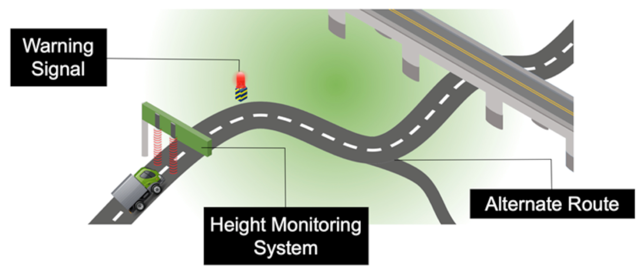
In this paper, we report an overheight vehicle detection system (OVDS) using both laser and ultrasonic sensors with wireless LTE and RF communication to an off-site central command and a warning signal, respectively. We focus on the main purposes of such system, height detection and warning, while addressing the most common issues observed in installed systems. The majority of these issues are error correction, false positives, power, cost, and speed. A full implementation and installation of such system is proposed in
Figure 1, with the ability to monitor and profile moving vehicles to determine if they are overheight, and further warning them to take appropriate action. This is implemented in two different lanes, with the capability of expansion in the future.
2. Methodology and Design
2.1. Design Overview
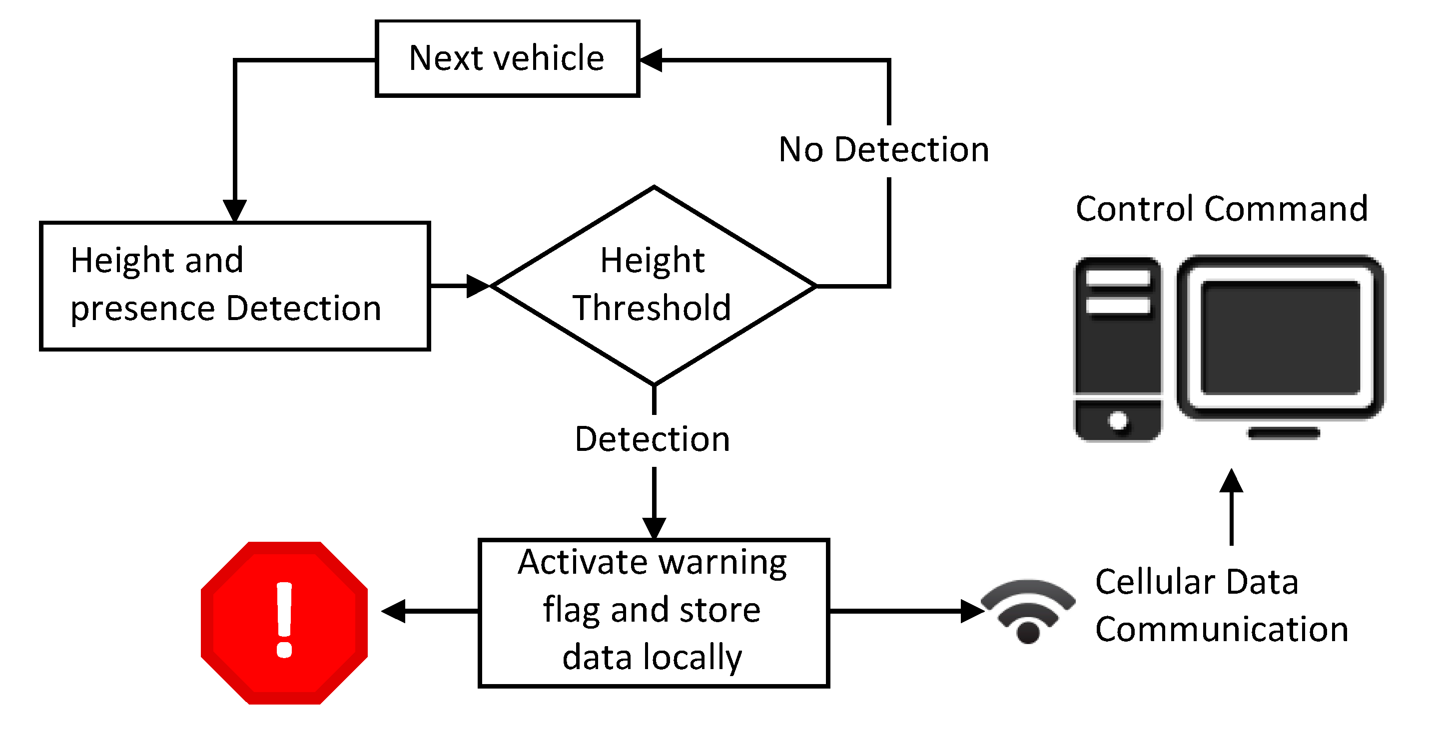
The overall functionality of the system is shown in
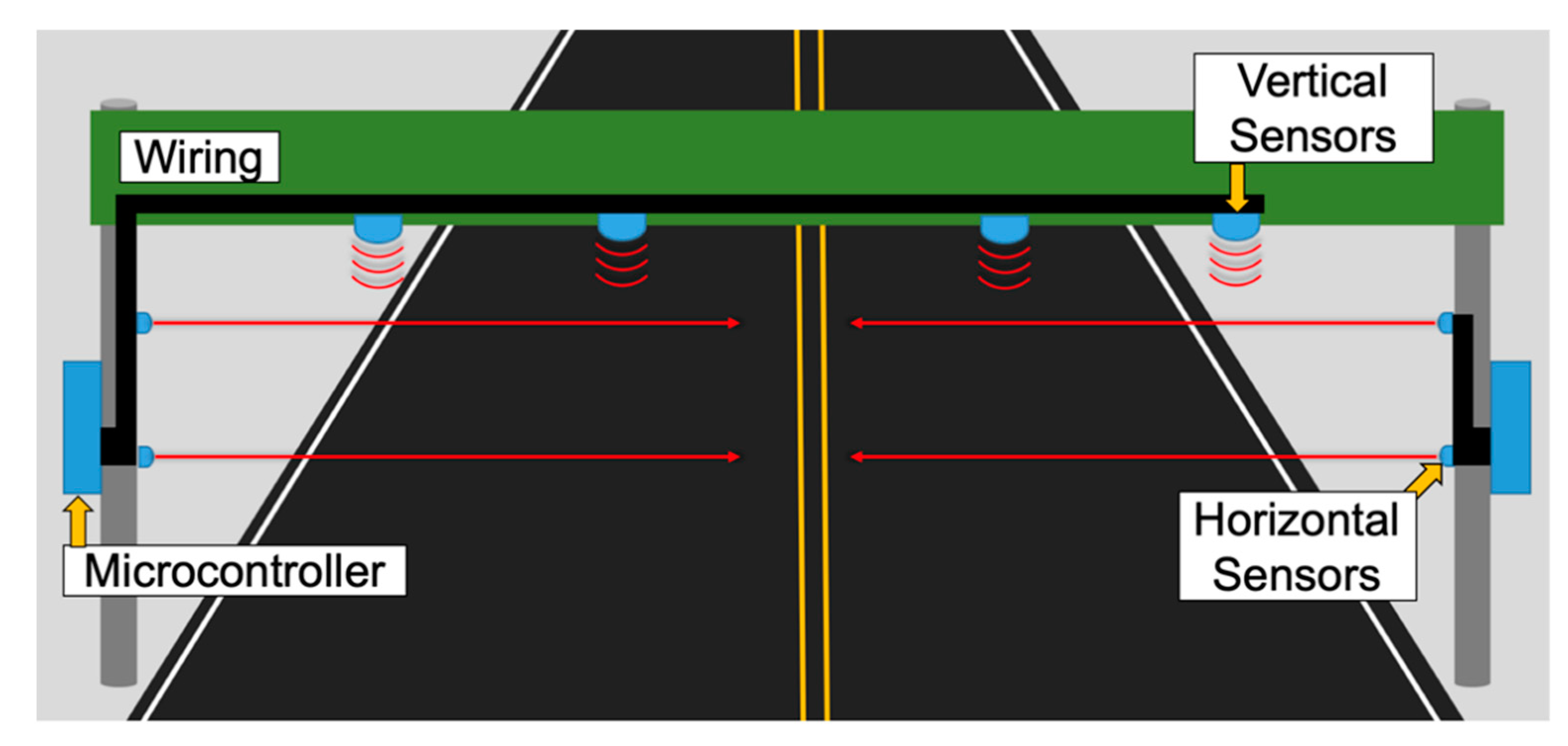
Figure 2, where continuous communication between the sensor system and both a warning signal and a control command is crucial for detection, logging, and warning of an overheight vehicle. The proposed system is divided into two subsystems. The first one determines whether the incoming vehicle is clear to pass, depending on its height. This can be accomplished with several different methods. One option relies on distance sensors placed directly above the street (either under a crossing bridge or under a sign). These sensors would detect the exact height of each passing vehicle. A second option utilizes an array of laser sensors placed on both sides of the road at specific heights. This would basically allow the detection of the highest point of a vehicle and indicate whether or not it can pass. For the overheight decision-making in our system, we use not one but a combination of both vertical and horizontal sensors to determine if a vehicle is clear to pass an upcoming obstacle. This decision-making process is described in
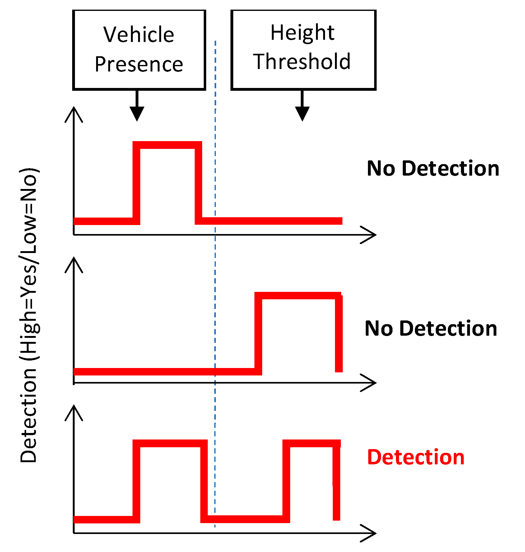
Figure 3 and will be further detailed in the next section.
The second subsystem acts in reaction to what the first has determined about a vehicle. This system consists of an indicator to the driver about their vehicle not being able to pass and to take the nearest bypass road. Once a vehicle is determined to be outside the accepted height threshold, this second subsystem will also log and send data about the event locally, including images, date, time, and height information. Furthermore, it will use cellular data (via a subscriber identification module or SIM card or mobile hotspot) to communicate with the central command and send it the required and pre-determined information.
2.2. Sensor Determination
The main objective of the height profiling system is to determine the height of an incoming vehicle. For this purpose, different distance sensors exist that satisfy the required specifications. Laser sensors consists of an emitter that will send a pulse of laser light and measure the reflected pulse as it returns to a receiver. The time difference between these two events is measured with high precision and converted to a distance measurement. These beams travel at the speed of light, yielding high rate of reading to detect fast moving objects. Laser sensors are usually more expensive and work for ranges up to 200 m (or 650 ft). State-of-the-art laser sensors can reach a signal obtaining rate of up to 1000 samples per second. Each laser-based sensor can consume up to 100 mA of current with a 5 V voltage supply, with operating temperatures of up to 85 °C (or 185 °F). A typical laser sensor would then consume around 500 mW per each sensor, on average.
On the other hand, ultrasonic sensors work on similar principles. The difference is that high frequencies are sent instead of light beams and reflections are measured. These sensors have lower costs but can reach distances up to 20 m (or 65 ft), on average. Sound waves, however, travel slower and are more prone to inaccurate measures due to additional noise and a lower intensity signal (light is easier to focus than sound). However, ultrasonic sensors can compensate possible errors of laser sensors during heavy rain or dense fog conditions. Ultrasonic sensors can reach a signal of up to 500 samples per second. Each ultrasonic based sensor can consume up to 25 mA of current with a 3.3 V voltage supply, with operating temperatures of up to 65 °C (or 150 °F). A typical ultrasonic sensor consumes around 12.5 mW per each sensor, on average.
These time-of-flight (ToF) sensors are a viable option due to high read rate (around 1000 Hz) and acceptable power consumption of around 600 mW per each sensor, on average. These sensors also utilize laser-based transmitters and can work at long ranges of up to 40 m (or 130 ft) with minimal crosstalk.
For this reason, there has been extensive use for these types of sensors in situations where high-speed detection is required, such as obstacle and collision avoidance or high-speed autonomous navigation [
9,
10,
11]. This purpose satisfies the needs of our system, since high speed vehicles need to be profiled in an accurate way.
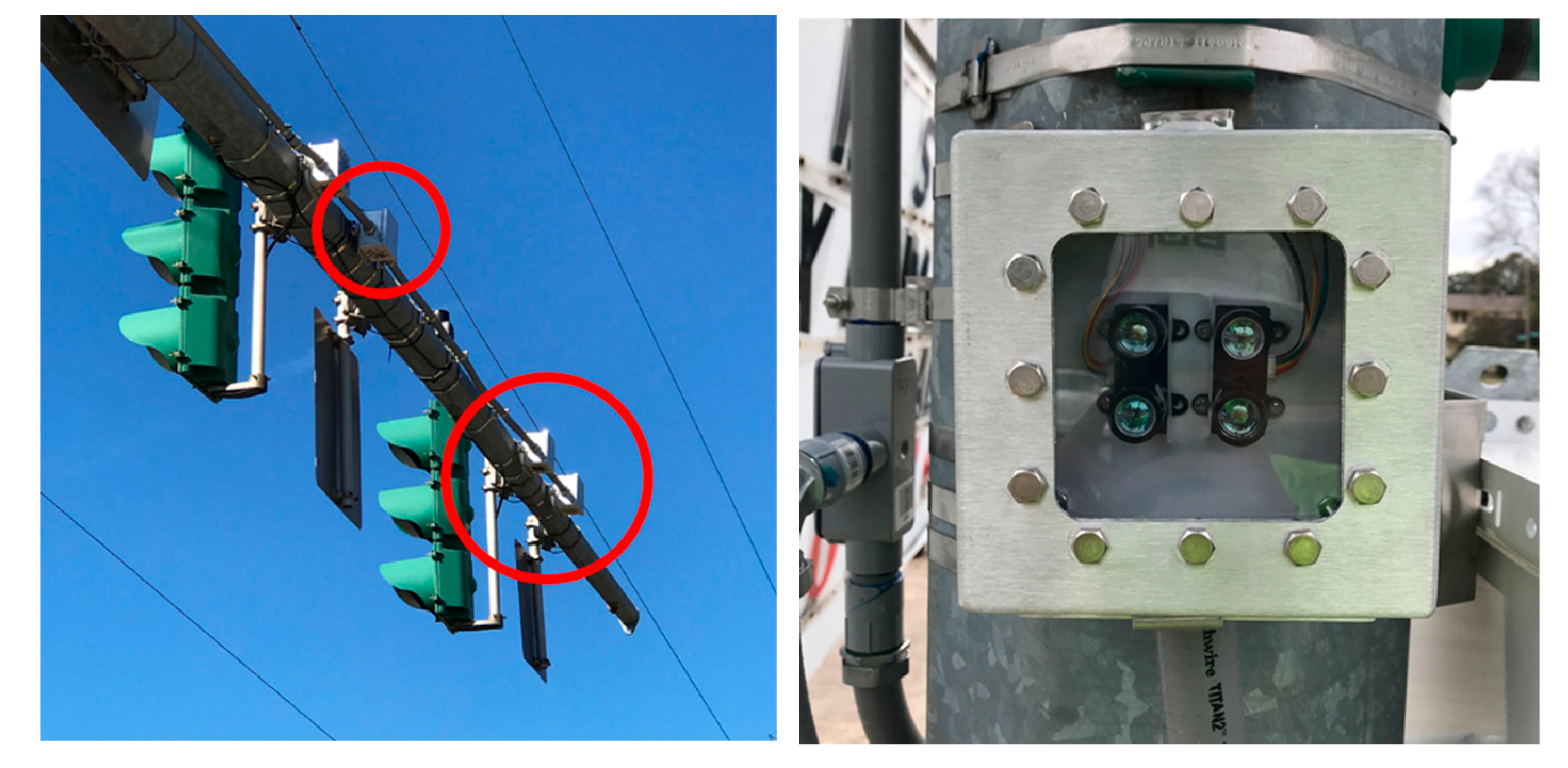
The combination placement of these sensors to achieve the objective involves placing laser sensors on both sides of the road, and on top of the lanes. This hybrid lateral/vertical arrangement of sensors has the advantages of lateral and vertical sensors in one system.
This system utilizes a vertical setup with overhead sensors to determine the height of a vehicle. These sensors can be placed either under an intersecting bridge or already existing structure, or on a specifically built structure. The sensors placed have to be fast enough to detect every passing vehicle at high speeds. Infrared lasers and ultrasonic sensors can both measure under the required conditions.
On the other hand, horizontal sensors, although also laser-based, do not measure the distance from the emitter to the vehicle for height, but determine the presence of the vehicle and in which lane it is located using distance windows. These further aid in error correction and false positive prevention. Based on distance thresholds on each, the sensing systems determine if (1) a vehicle is actually present at the time of detection, and (2) the vehicle’s height profile and if it exceeds a height threshold. This directly aims to remove the false positive issues aforementioned as well as that can occur from external sources of noise (i.e., passing animals, weather, etc.) that might trigger a high vehicle warning if not accounted for. A simple decision schema is shown in
Figure 3, where a detection is only logged if both presence and height threshold occur within the same time frame.
2.3. Wireless Communication
A considerable distance between the sensor and the warning sign must be used in the system for the driver to have enough time to see and react to the warning telling them to take the nearest bypass exit. Cellular data is used to communicate with the central command for data logging purposes. This data transmission consists of reports, pictures, and time logging of events where an overheight vehicle is detected. Radio frequency (RF) is used to trigger the warning sign about 500 ft away from the sensors. The transmitter side (sensor sign) can send an analog signal (single frequency tone) to the receiver end. The receiver end interprets that signal as a height threshold violation and promptly activates the warning.
4. Results and Discussion
All sensors were calibrated and characterized using known values of distance to street (ground with no car) and distance between poles. These were further compared with thresholds to divide lanes (lanes 1 and 2 in this case) and height/presence. We used the decision-making algorithm depicted in
Figure 2 for two lanes, where they were demonstrated to work using all installed components aforementioned. Further calibrations and performance results were performed using empty streets and known values, including lane width, street dimensions, distances between poles and distance between sensors. These were also accounted for with variations in environment, field of view, and temperature surrounding each sensor.
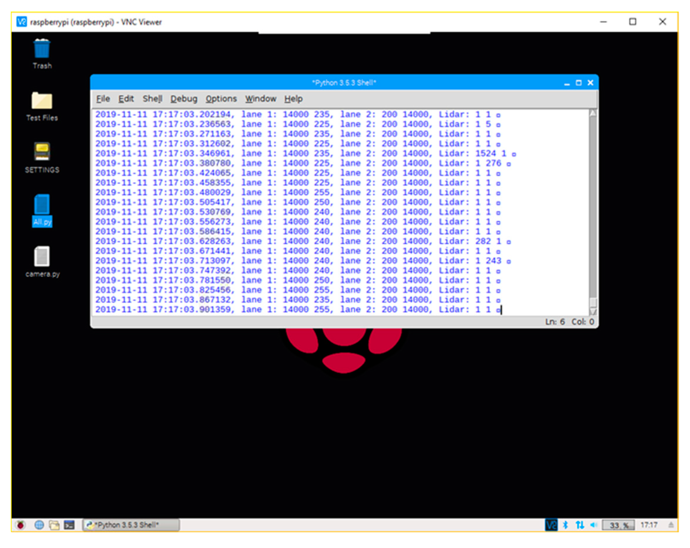
For monitoring, a remote VNC client was installed in the loggers. This was implemented to access all data, images, and reports remotely from anywhere with an internet connection. This also allowed for troubleshooting and code modifications without visiting the installation site. An overview of the user interface is observed in
Figure 6, showing all raw data through a serial port and images as obtained continuously when the system is running.
All sensors are active at all times, including the camera for real-time monitoring. Initially, horizontal sensor values are collected and averaged to determine the lane. This includes filtering and averaging to avoid noise. This value is first compared to a presence threshold, which indicates if there is a vehicle present in any of the two lanes being observed. If this is the case, the averaged value is evaluated to the midpoint between the two lanes (is the value higher or lower?) and used to determine in which lane the vehicle is present.
When a lane is determined, vertical sensor data is used to calculate an average sensor-to-vehicle distance. This is then subtracted from the calibration measurement (which is the sensor-to-ground distance) to calculate average vehicle height.
Figure 6 shows an example of the data collected from a vertical and horizontal sensor within a small period of time. The vertical data represents the time of flight time sensing from each distance sensor, in milliseconds, and is used to calculate the vehicle height. The horizontal data, on the other hand, is also a time of flight measurement which is used for the purpose of determining if a vehicle is present and in which lane. Both sensors have been normalized to zero in order to account for outlying data.
Once this data has been collected, we determine if the vehicle height exceeds a previously determined threshold, meaning that the vehicle is too high. If this is the case, height data, along with vertical data and date/time are logged, and the warning signal pin will be activated. This also triggers six camera frames to be stored in order to capture an image of the vehicle being profiled. All sensor data for vehicles exceeding the threshold, along with time-stamped images, are appended to a report that will be sent periodically or obtained on-demand.
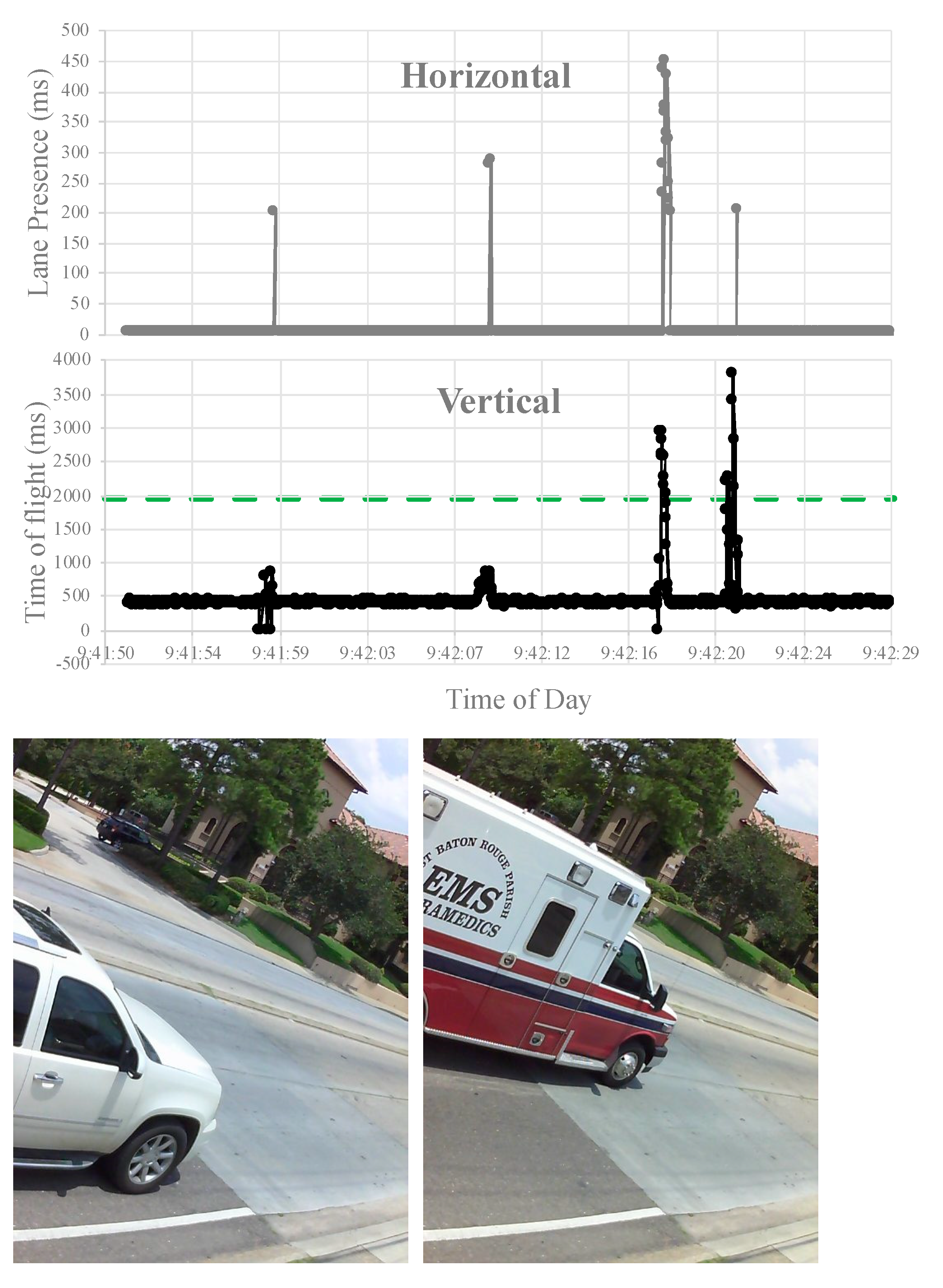
For each incident, height is calculated based on the average distance from the vehicle to the sensor, when compared to the distance between the sensor and the ground. This value is further used to categorize each vehicle based on its class. These classes include compact, mini SUV, large SUV, and truck. With additional calibration and noise reduction, the system is able to accurately show the height of each vehicle as it passes its threshold. The sample resulting picture and the measured height can be observed in
Figure 7, with the clearest of the six frames taken saved. These samples include the time index used to calculate the time of day, as well as the resulting height and category of the vehicle. From the data shown in
Figure 7, vertical and horizontal peaks determine both the height and presence of a vehicle at a given time. The horizontal data, measures in milliseconds, determines not only the presence of a vehicle in the sensor’s line of sight, but also in which lane it is detected. Higher peaks translate to further lane intersections, with no detections normalized to 0. On the other hand, vertical data is measured by the calibration value in milliseconds minus the detected time of flight to a vehicle. This results in a time of flight measurement directly related to the vehicle’s height.
With an arbitrary threshold set at 2000 ms, the vertical alarm was triggered in the red regions observed above. A detection is logged if and only if both peaks are triggered at the same time, as described in
Figure 3, resulting in the two different instances aforementioned. If only one is detected, however, the system considers it as noise and no detection is logged or reported.
Other highlights to note include the collection of data based on distance to sensor thresholds, upon which the algorithm logs the time/date of the data point and stores its corresponding picture. Normalization of pictures being taken is implemented to save storage space on the on-site computer, meaning that the camera will only take six pictures when a presence threshold is activated, as mentioned before.
We added anti-crosstalk code due to repeated sensors placed for each lane or level and enabled the command for the sensors which activates them one by one. There exists negligible delay in signal acquisition so it should not affect the system functionality. Sample resulting images and data were locally stored in the on-site computer to be sent in periodic reports via email, text message, or other ways of communication using the LTE connection.


