1. Introduction
The common practice of adding stories made of structural steel upon an existing reinforced concrete (r/c) building is mainly based on empirical engineering rules, as current seismic design building codes, e.g., Eurocode 8 [
1], provide design recommendations for structures made from the same material throughout the whole building. Nevertheless, buildings constructed by r/c at their lower story(ies) and structural steel at their upper story(ies) constitute a building type that is very often met in engineering praxis. Leaving aside the treatment of the added stories as a secondary structure appended to the primary structure [
2], implying thus, a substantially reduced in size and weight secondary structure with respect to the primary one, this work focuses on the case in which the upper steel stories tend to have the same size in-plan with the lower r/c ones, thereby adding a significant weight to them. Therefore, the resulting structure is termed as mixed and its dynamic behavior has to be assessed by either modal superposition or time-domain analysis [
2].
This study deals exclusively with vertically mixed r/c-steel buildings. The term ‘vertically’ is used to denote that the material of the structural members of each story is either r/c or steel. If both r/c and steel materials are used for the structural members in each story, then the term ‘horizontally’ mixed building fits. A representative type of a horizontally mixed building is the one in which r/c shear walls coupled with steel beams, e.g., [
3,
4], are employed. Horizontally mixed buildings of the aforementioned type as well as of other types and/or materials, e.g., [
5,
6,
7], have been proposed and investigated in detail, but are not considered in this study. Moreover, it should be stressed that the dynamic (seismic) behavior of horizontally mixed buildings is totally different from that of vertically mixed ones. On the other hand, one other thing to note is that the vertically mixed buildings studied herein cannot be viewed as (r/c-steel) composite buildings because for the latter, by definition, the section of the structural members and/or the slabs is composite, i.e., from r/c and steel working cooperatively.
Despite the practical interest associated with vertically mixed r/c-steel buildings, only limited research has been performed so far on their seismic behavior and design, being at the same time focused on moment-resisting frames (MRFs) [
8,
9]. Oddly enough, being the damping ratio of the lower (r/c) and upper (steel) parts different (the usually assumed values are 5% and 2%, respectively), several studies dealing with the quantification of a uniform damping ratio of vertically mixed buildings can be found in literature, e.g., [
10,
11,
12,
13,
14,
15,
16]. This uniform damping ratio can be used in the context of either response spectrum or time-history analysis, even though a specific value for the damping ratio of vertically mixed r/c-steel buildings is absent in [
1]. As mentioned in a later section of this paper, selecting one value for this uniform damping ratio is necessary, otherwise, the engineer should consider several values of this ratio and, thus, perform a significant number of seismic analyses.
In addition to the aforementioned limited research performed so far, modern seismic codes, e.g., Eurocode 8 [
1], do not provide specific recommendations for the seismic design of vertically mixed r/c-steel buildings, but rely instead on the seismic design performed separately for their r/c and steel parts. Thus, there is a need to investigate the seismic behavior of realistic mixed buildings, especially from the perspective of performance-based seismic design.
For this reason, a 3-D numerical model is employed and five kinds of typically met in engineering praxis r/c-steel mixed buildings are simulated. Two cases of the support condition of the lowest steel story to the upper r/c one are studied: (i) fixed in both horizontal directions and (ii) pinned in one direction and fixed in the other. The r/c and steel parts of the mixed buildings are initially designed as separate structures by making use of the relevant seismic design guidelines of Eurocode 8 in conjunction with Eurocodes 2 and 3 [
17,
18].
The mixed buildings are then assessed by non-linear time-history (NLTH) analyses employing a set of 11 near-fault seismic motions. These seismic motions are deliberately chosen because they have been repeatedly reported in the literature to cause large seismic demands even to building structures designed according to modern seismic codes, e.g., [
19,
20]. Global seismic response indices, i.e., the interstorey drift ratio (IDR), the residual interstorey drift ratio (RIDR) and peak floor (absolute) acceleration (PFA), are computed and their height-wise distribution is plotted. Using these plots, the maximum values for IDR, RIDR and PFA (normalized to peak-ground acceleration) are easily identified and then discussed in detail based on comparing the two aforementioned kinds of support conditions and checking the satisfaction of specific seismic performance limits. Conclusions regarding the expected seismic behavior of vertically mixed r/c-steel buildings under near-fault seismic motions are drawn. Finally, the need to introduce specific design recommendations for vertically mixed r/c-steel buildings in modern seismic codes is stressed.
2. Mixed Buildings Considered
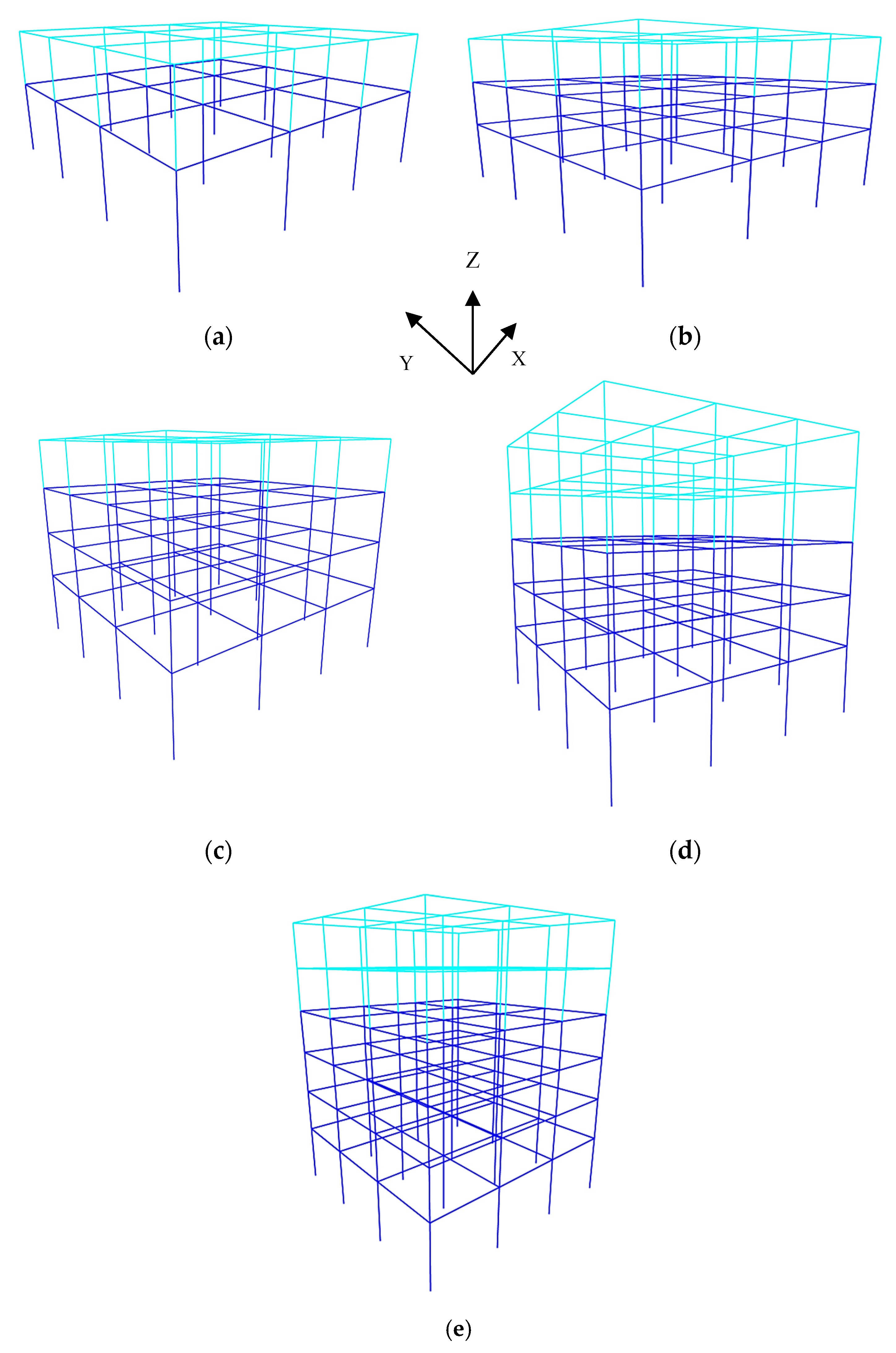
The two-, three-, four-, five- and six-story 3-D mixed r/c-steel buildings shown in
Figure 1a–e are considered. In particular, in
Figure 1a–e the lower story(ies), shown with blue color, are assumed to be constructed by r/c, whereas the upper story(ies) shown with cyan color, are assumed to be constructed by steel. In both horizontal directions, the buildings shown in
Figure 1a–e behave as MRFs. All buildings have a square plan configuration of
and three identical spans of
are formed in each one of the two horizontal directions. The global coordinate system is also shown in
Figure 1.
Except for the height of the bottom story (r/c), which is
, the height of each other story (r/c or steel) is
. Diaphragm action is assumed for each floor due to the presence of r/c and composite slabs having a thickness of
. The materials used for the r/c part of the mixed building are C25/30 and B500c for concrete and steel reinforcement [
17], respectively, whereas the steel grade for both beams and columns of the steel part of the mixed building is S355 [
18].
The mixed buildings of
Figure 1a–e are designed according to the provisions of relevant Eurocodes [
1,
17,
18] as ordinary buildings (importance factor is 1.0). The gravity load consists of dead load
and live load
. Load
is
on floors and
on walls. The mixed buildings are seismically designed for a ductility class medium (DCM), according to [
1], and are assumed to be founded in a site with
. The design spectrum is that of type 1, viscous damping ratio 5% and soil type C.
The effect of soil-structure interaction is assumed to be small and hence is not included in the seismic analysis. The maximum values of the behavior factor
permitted by [
1] for DCM are 3.9 and 4.0 for r/c and steel MRFs, respectively. It is recalled that in [
1] the value of
q may be different in the two horizontal directions of the structure, although the ductility class shall be the same in these directions. Seismic loading is considered for both horizontal directions following the 30% combination rule of [
1]. An accidental eccentricity of 5% is considered [
1].
The seismic design checks are performed separately for the r/c and steel parts of the mixed buildings, assuming the aforementioned maximum values of
. The inter-story drift sensitivity coefficient
in both horizontal directions of the mixed buildings has been taken into account and the final design is checked against the damage limitation criterion of [
1], assuming non-structural elements of brittle materials. Final sections for beams and columns of the r/c and steel parts of the mixed buildings (a)–(e) of
Figure 1 are shown in
Table 1. It should be noted that for each r/c story the square cross-sections of all columns has been chosen to be the same. On the other hand, the orientation of the steel columns follows
Figure 2, essentially leading to a strong perimeter steel frame.
Concerning the support condition of the lowest steel story to the upper r/c story, two cases are examined: (i) the steel columns behave as fixed (carrying moment) in both horizontal directions of the mixed building and (ii) the steel columns behave as fixed in one horizontal direction (cross-sectional minor axis) and nominally pinned (carry small or no moment) in the other one (cross-sectional major axis). This distinction regarding support conditions is of utmost importance taking into account that, in all likelihood, the drilled-in epoxy type anchor rods used in the base plate connections of the steel columns cannot be fully anchored into a pre-existing r/c column, thus the moment capacity of the base-plate connections may be small. Moreover, the number and placement of anchor rods is directly related to the dimensions of the r/c column as well as to the presence of the steel reinforcement and stirrups in it. Thus, under normal circumstances, the engineer should perform several analyses of the mixed building, considering different degrees of freedom for the support of the steel structure upon the r/c one.
For reasons of comparison between the two aforementioned kinds of support conditions, the sections of all steel and r/c members of the mixed buildings are considered to be those shown in
Table 1. As expected, the first significant modes of vibration of the mixed buildings of
Figure 1 for the cases of the fixed or fixed-pinned support conditions of the steel structure to the r/c one, are different. The first two translational modes and the third torsional one, along with their corresponding mass participating ratios in parentheses, are presented in
Table 2. In
Table 2, I and II denote fixed and fixed-pinned condition cases, respectively, whereas symbols (a)–(e) used for each mixed building follow
Figure 1.
With reference to
Figure 2, the mixed r/c-steel buildings shown in
Figure 1a–e are symmetrical and the difference between the center of stiffness and mass is found to be small. If unsymmetrical mixed buildings are considered, this difference becomes larger and should be taken into account in the design.
3. Seismic Motions and Modeling of Mixed Structures for NLTH Analyses
The mixed buildings of
Figure 1 are subjected to 3-D NLTH analyses, employing the two horizontal components that correspond to each one of the eleven (11) near-fault seismic motions (downloaded from [
21]) presented in
Table 3. In this table, data with the concerning earthquake name, location, year, recording station, moment magnitude M
w and peak ground acceleration (PGA) of the two horizontal components are provided. More information regarding the location, soil type, proximity to fault, etc., for the near-fault seismic motions of
Table 3 can be found in [
21].
Being recorded close to the ruptured fault, the near-fault seismic motions of
Table 3 are strongly influenced by directivity effects. The two horizontal components of each seismic motion are used interchangeably for the two horizontal axes X and Y, shown in
Figure 1, of the mixed buildings, thus, doubling the number of NLTH analyses performed. Therefore, it is assumed that the angle of orientation of the seismic motion with respect to the horizontal direction of the building, is either 0° or 90°. Due to the symmetry of the mixed buildings studied herein, there is no need to perform a further variation of the angle of orientation of seismic motion to the horizontal directions of the buildings. On the other hand, in the NLTH analyses conducted herein, the two horizontal components of the near-fault ground motions of
Table 3 have not been rotated to the angle of the seismic fault, i.e., to the fault-normal and fault-parallel directions, and have been used as recorded. It is believed that the error introduced to the maximum seismic response by not performing the rotation of the recorded components is small and hence the results presented in the following are credible.
As stated in the Introduction, a potential problem in the computation of the seismic response of a mixed building arises from the value of the damping ratio assumed, at least for the significant modes of vibration. In this work, the approach proposed by Sivandi-Pour et al. [
12] is followed and uniform (common) values of damping ratios for the first few modes of vibration are calculated. These damping ratio values for each of the mixed buildings of
Figure 1 (following symbols (a)–(e)) are provided in
Table 4, and are then used to form the damping matrix needed for the NLTH analyses.
For the execution of NLTH analyses, the computer program RUAUMOKO 3-D [
22] is utilized. In particular: (i) both geometrical and material nonlinearities are considered; (ii) beam and column members are modeled using typical frame elements and their inelastic behavior is taken into account using point plastic hinges at their both ends. The formation of plastic hinges takes place due to uniaxial bending in beams and axial force with biaxial moment interaction in columns. A detailed joint modelling of beam-to-column connection is not included in the NLTH analyses, upon the assumption of well-detailed steel and r/c joints provided by the design rules [
1]. Failure of r/c members in shear before their bending failure is excluded if the capacity design provisions of [
1] are applied.
The system of equations of motion solved for each non-linear structure has the form , where M, C and K are the mass, viscous damping and stiffness matrices, respectively, u is the vector of the lateral displacement of the structure relative to the ground, is the ground seismic acceleration, I is the unit vector, F is the vector of the nodal internal forces, which depend nonlinearly on the deformation and the rest of the matrices and vectors and overdots denote differentiation with respect to time t. This system is solved by stepwise time integration.
A 2% strain hardening is assumed for steel members, whereas the limits for their plastic hinge rotations, concerning the seismic performance levels, are those of ASCE 41-17 [
23]. The modified Takeda hysteresis model [
22] is employed to model stiffness degradation and strength deterioration of the r/c members. The post-yield hardening ratio of r/c members is considered to be 5%. The backbone moment M-rotation θ curve is defined as in ASCE 41-17 [
23]. An effective (cracked) stiffness equal to 0.30 and 0.35 times the initial (uncracked) stiffness for columns and beams, respectively, is assumed.
Non-structural elements and soil-structure interaction effects are not modelled for the NLTH analyses conducted in this work. The total number of NLTH analyses performed for each mixed building of
Figure 1 is 44, i.e., 11 (seismic motions) times two (changing the two horizontal components of seismic motion along the two horizontal axes of the buildings) times two (fixed and fixed-pinned support conditions of the steel structure to the r/c one).
4. Seismic Response Results and Discussion
In this section, the seismic response results of the mixed buildings of
Figure 1, when subjected to the seismic motions of
Table 3, are presented and discussed. More specifically, plots portraying height-wise distributions of the maximum IDR, RDIR and PFA in both horizontal directions X and Y of the mixed building are provided separately for the two aforementioned cases of support condition of the steel structure to the r/c one, i.e., fixed and fixed-pinned. It is noted that in these plots: (i) the vertical axis is the cumulative floor height, which is
for the bottom (r/c) story and increases per
for each other story (r/c or steel); (ii) the symbols (in legends) 0 and 90 are used in conjunction with the name of the seismic motion (following
Table 3) to distinguish the mutual change between the two horizontal components of seismic motion with respect to the horizontal directions X and Y of the mixed building; (iii) the code names (in legends) of the seismic motions can be found in
Table 3.
Limit IDR values for the seismic performance levels IO (Immediate Occupancy), DC (Damage Control), LS (Life Safety) and CP (Collapse Prevention) are those of SEAOC [
24] and read: 0.5%, 1.5%, 2.5% and 4.0%, respectively, for r/c MRFs, and 0.7%, 1.5%, 2.5% and 5.0%, respectively, for steel MRFs. The stress–strain state of the building structures at the levels DC, LS and CP of seismic response induced by the near-fault seismic motions in
Table 3, is essentially non-linear. Limit values for plastic hinge rotation associated with the IO, DC, LS and CP seismic performance levels are those defined in ASCE 41-17 [
23].
Concerning the RIDR, the limit value of 0.5% is selected [
25]. The 0.5% maximum permissible of RIDR is assumed to hold for both the r/c and steel stories of the mixed building. Limit PFA values for the aforementioned IO, DC, LS and CP seismic performance levels do not exist in the literature. Thus, PFA values are simply normalized to the PGA values given in
Table 3. This normalization is performed separately for the X and Y directions of the mixed building, following the 0 and 90 symbolization, as explained above.
Failure of the mixed building occurs if one or more of the following is satisfied: (i) plastic hinge rotations at the lower-end of the bottom (r/c) story column and at the ends of the r/c and steel beams, are beyond the limit values corresponding to the LS seismic performance level; (ii) a soft-story mechanism is formed and (iii) the threshold RIDR value of 0.5% is surpassed.
Due to space limitations, only plots of the maximum RIDR and PFA/PGA height-wise distributions considering the two support conditions of the steel structure to the r/c one, are shown in the following. In these plots, only the relevant results from these NLTH analyses that have converged are included. Furthermore, it should be recalled that when near-fault seismic motions influenced by directivity effects (as those of
Table 3) are employed in NLTH analyses, the maximum seismic response is expected to occur in this horizontal direction (0 or 90 as defined above) where the strongest ground motion component (mainly depends on the amplitude of the velocity pulse) is applied.
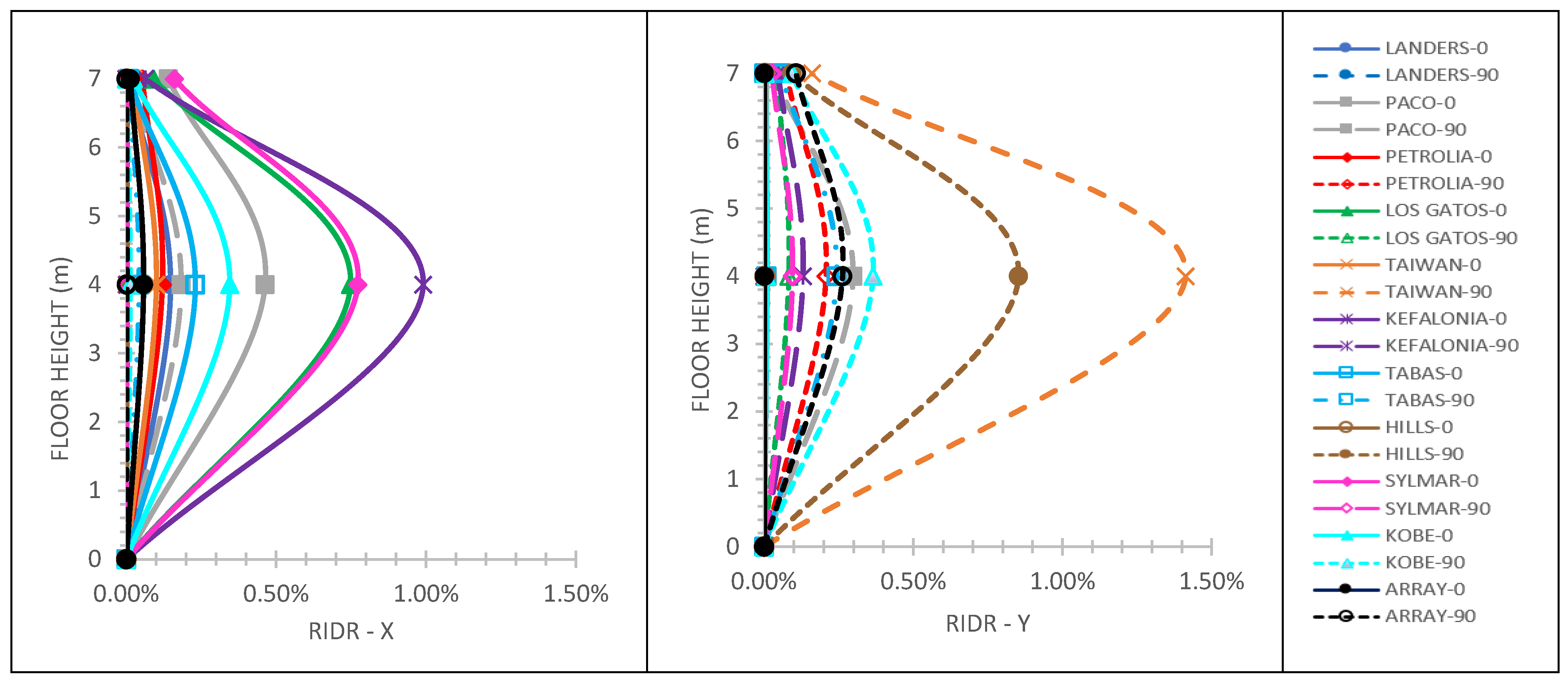
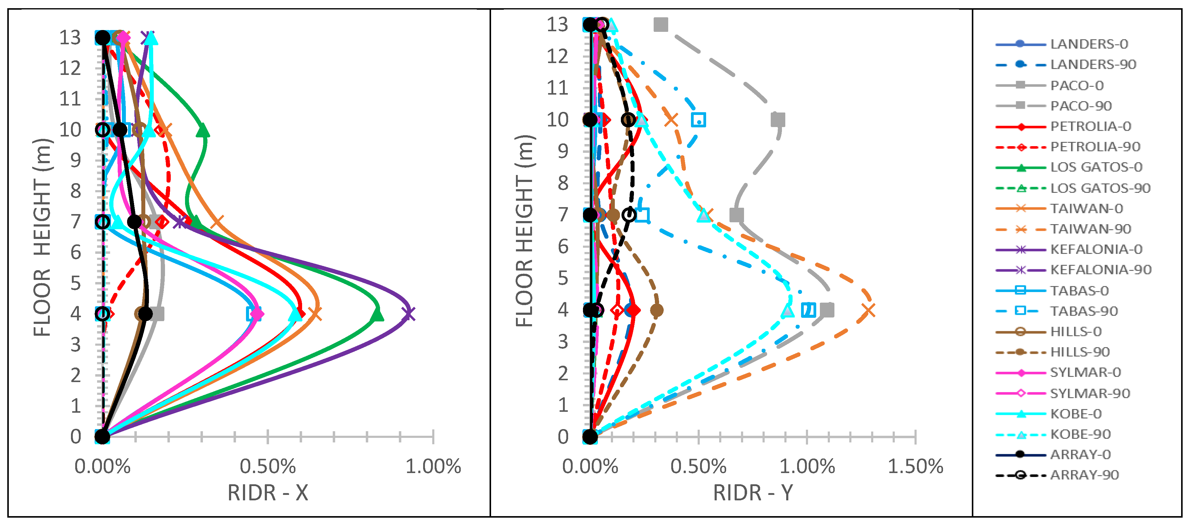
Starting with the two-story mixed building of
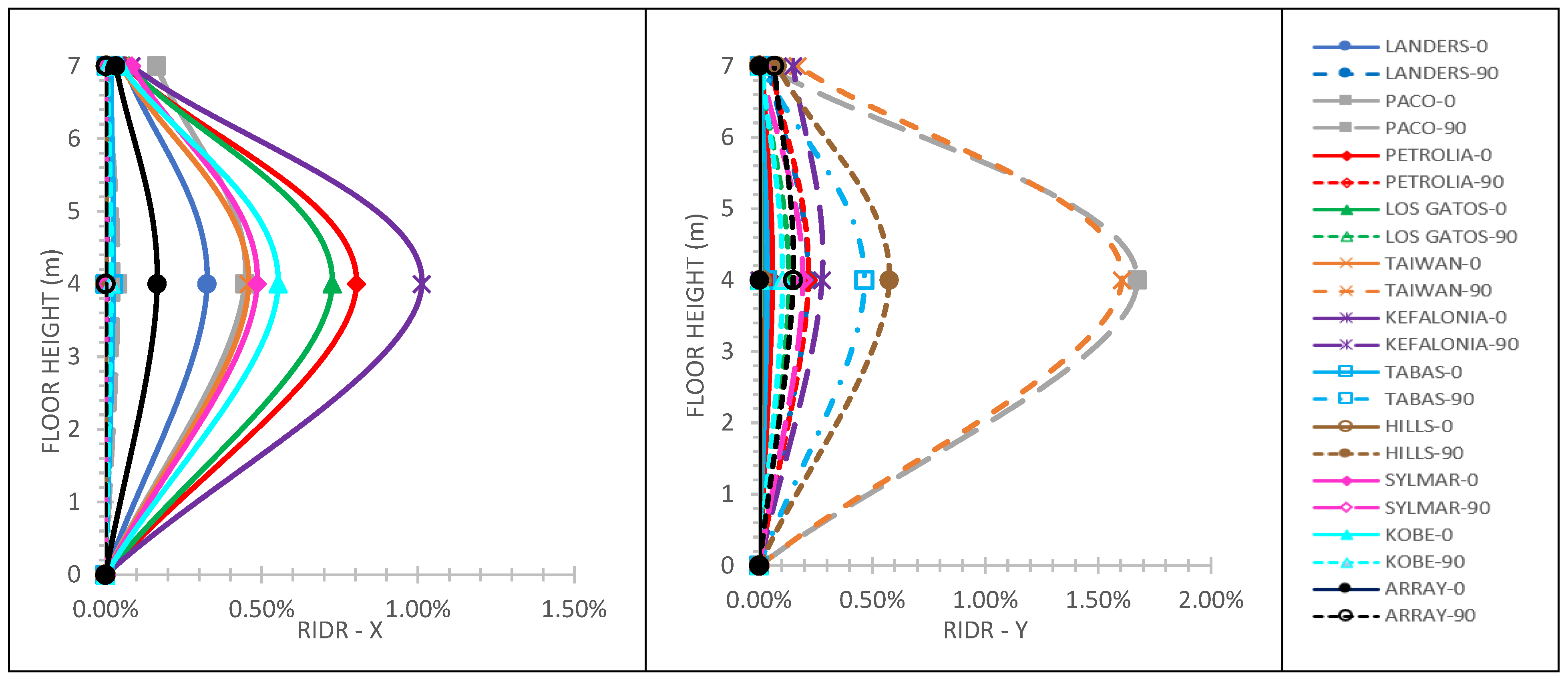
Figure 1a, the maximum IDR values computed for the X and Y horizontal directions of the building are 1.82% and 2.15%, respectively, for the case of fixed steel structure to the r/c one, and 3.30% and 2.97%, respectively, for the case of fixed-pinned steel structure to the r/c one.
Figure 3,
Figure 4,
Figure 5 and
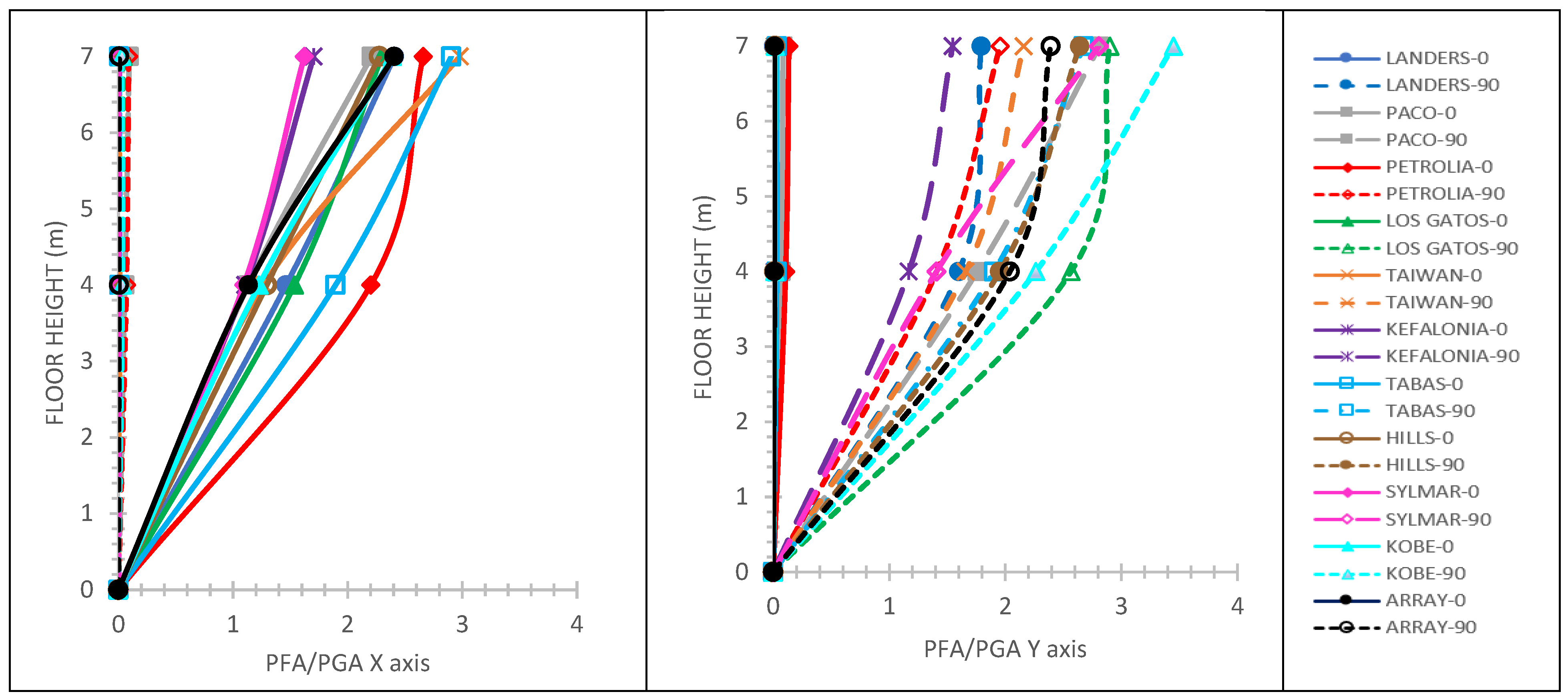
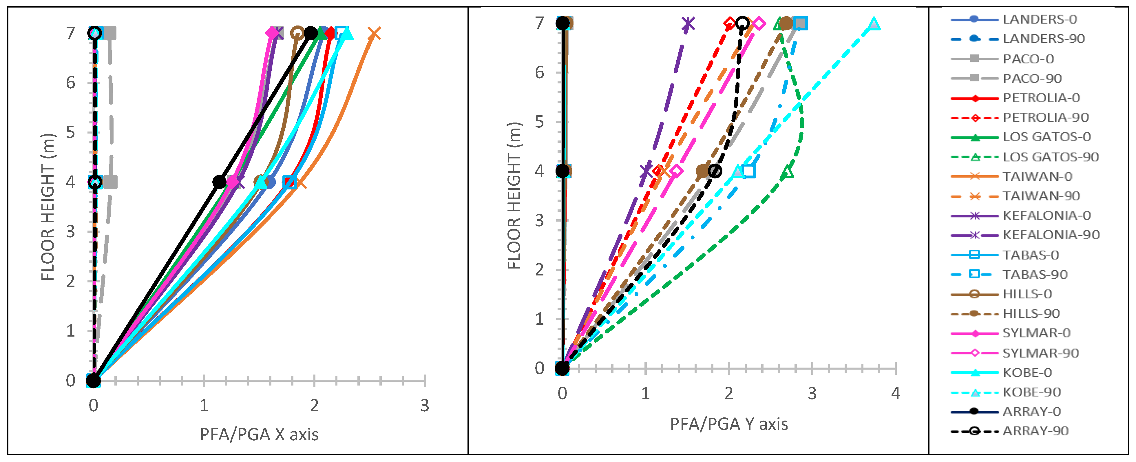
Figure 6 display that: (i) the 0.5% RIDR value is violated for five seismic motions in total (three and two seismic motions along with the X and Y horizontal directions of the building, respectively) for the case of the fixed steel structure to the r/c one; (ii) the 0.5% RIDR value is violated for seven seismic motions in total (four and three seismic motions along with the X and Y horizontal directions of the building, respectively) for the case of the fixed-pinned steel structure to the r/c one; (iii) for the X horizontal direction of the building, the maximum PFA/PGA is 2.54 and 2.98 for the cases of fixed and fixed-pinned, respectively, and the steel structure to the r/c one; (iv) for the Y horizontal direction of the building, the maximum PFA/PGA is 3.74 and 3.45 for the cases of fixed and fixed-pinned, respectively, and the steel structure to the r/c one.
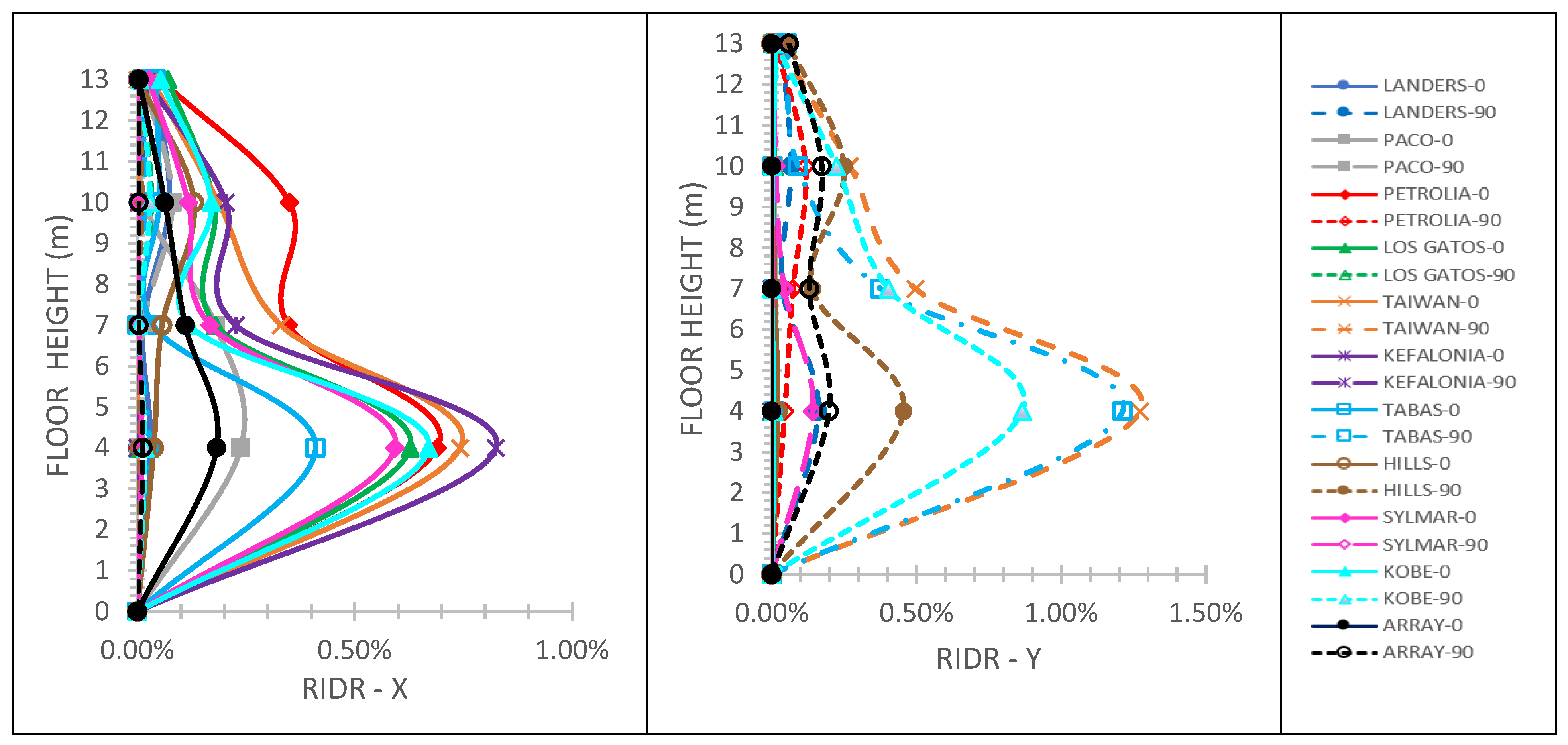
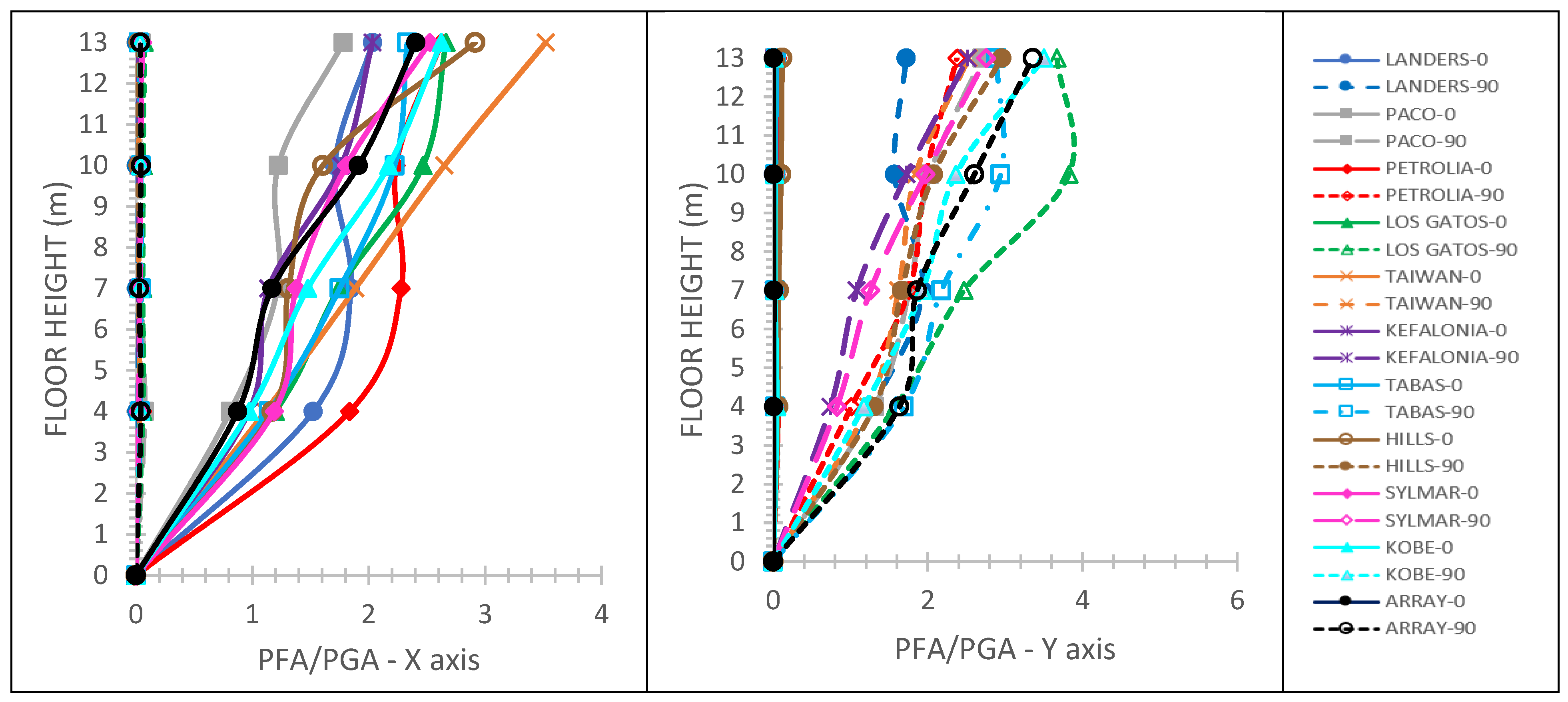
Next, the three-story mixed building of
Figure 1b is presented. The maximum IDR values computed for the X and Y horizontal directions of the building are 2.22% and 2.93%, respectively, for the case of fixed steel structure to the r/c one, and 2.20% and 2.92%, respectively, for the case of fixed-pinned steel structure to the r/c one.
Figure 7,
Figure 8,
Figure 9 and
Figure 10 display that: (i) the 0.5% RIDR value is violated for eight seismic motions in total (four seismic motions along with each one of the X and Y horizontal directions of the building, respectively) for the case of fixed steel structure to the r/c one; (ii) the 0.5% RIDR value is violated for nine seismic motions in total (four and five seismic motions along with the X and Y horizontal directions of the building, respectively) for the case of fixed-pinned steel structure to the r/c one; (iii) for the X horizontal direction of the building, maximum PFA/PGA is 2.76 and 3.17 for the cases of fixed and fixed-pinned, respectively, steel structure to the r/c one; (iv) for the Y horizontal direction of the building, maximum PFA/PGA is 3.24 and 3.37 for the cases of fixed and fixed-pinned, respectively, steel structure to the r/c one.
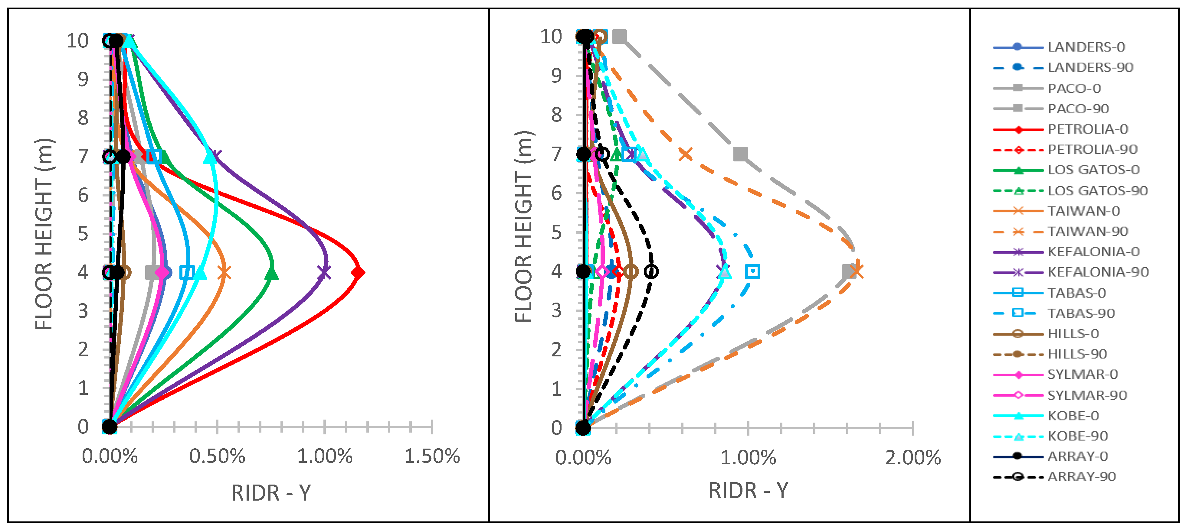
Moving to the RIDR and PFA/PGA results of the four-story mixed building of
Figure 1c, the maximum IDR values computed for the X and Y horizontal directions of the building are 3.45% and 2.42%, respectively, for the case of fixed steel structure to the r/c one, and 3.31% and 2.43%, respectively, for the case of fixed-pinned steel structure to the r/c one.
Figure 11,
Figure 12,
Figure 13 and
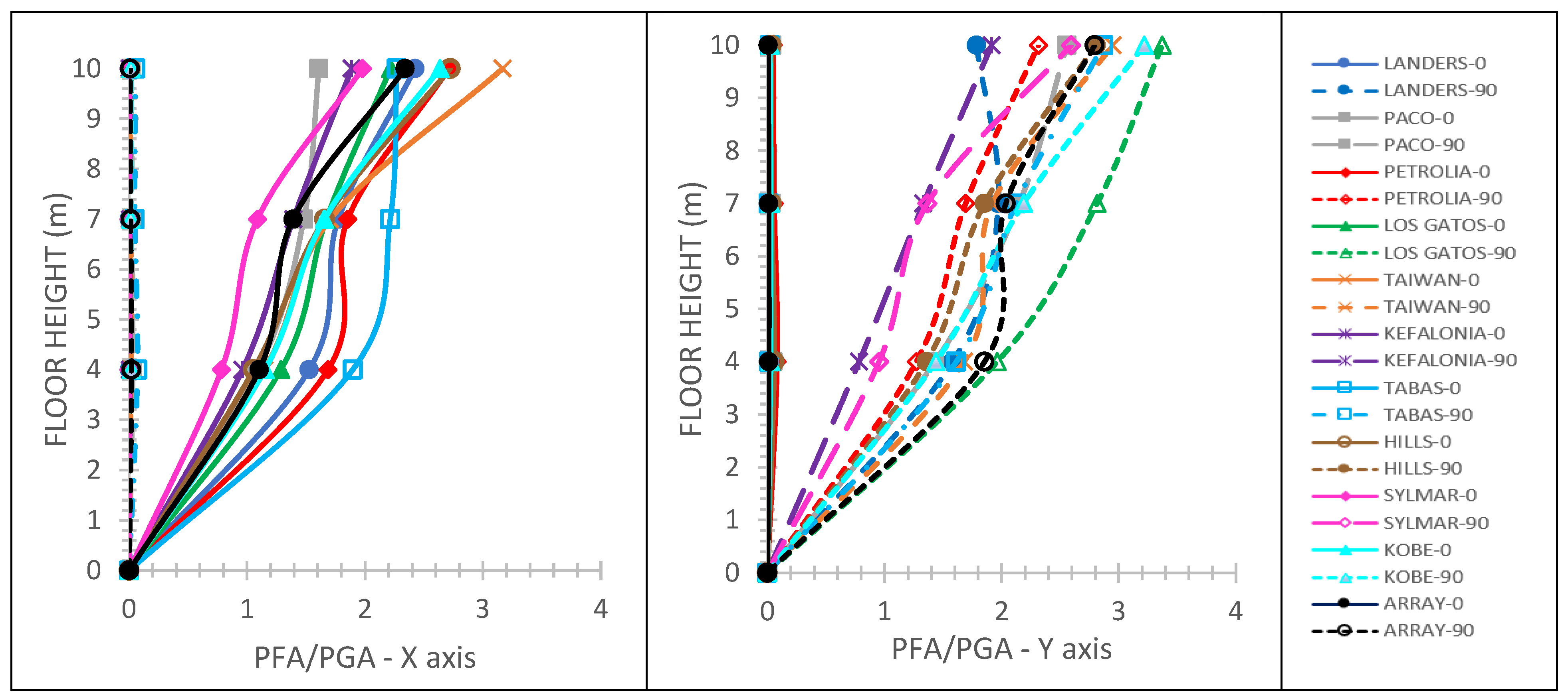
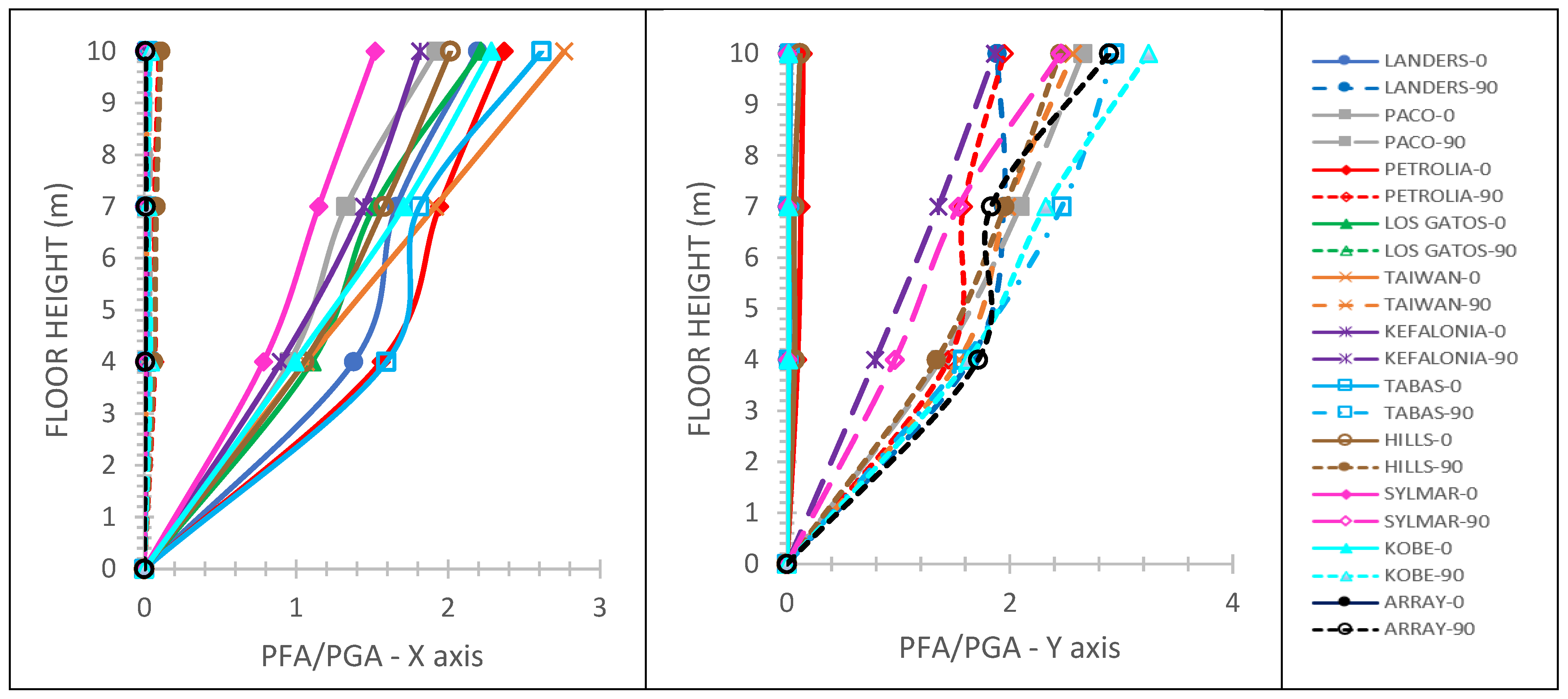
Figure 14 display that: (i) the 0.5% RIDR value is violated for nine seismic motions in total (five and four seismic motions along with the X and Y horizontal directions of the building, respectively) for the case of the fixed steel structure to the r/c one; (ii) the 0.5% RIDR value is violated for nine seismic motions in total (six and three seismic motions along with the X and Y horizontal directions of the building, respectively) for the case of fixed-pinned steel structure to the r/c one; (iii) for the X horizontal direction of the building, maximum PFA/PGA is 3.10 and 3.67 for the cases of fixed and fixed-pinned, respectively, steel structure to the r/c one; (iv) for the Y horizontal direction of the building, maximum PFA/PGA is 3.21 and 3.82 for the cases of fixed and fixed-pinned, respectively, for the steel structure to the r/c one.
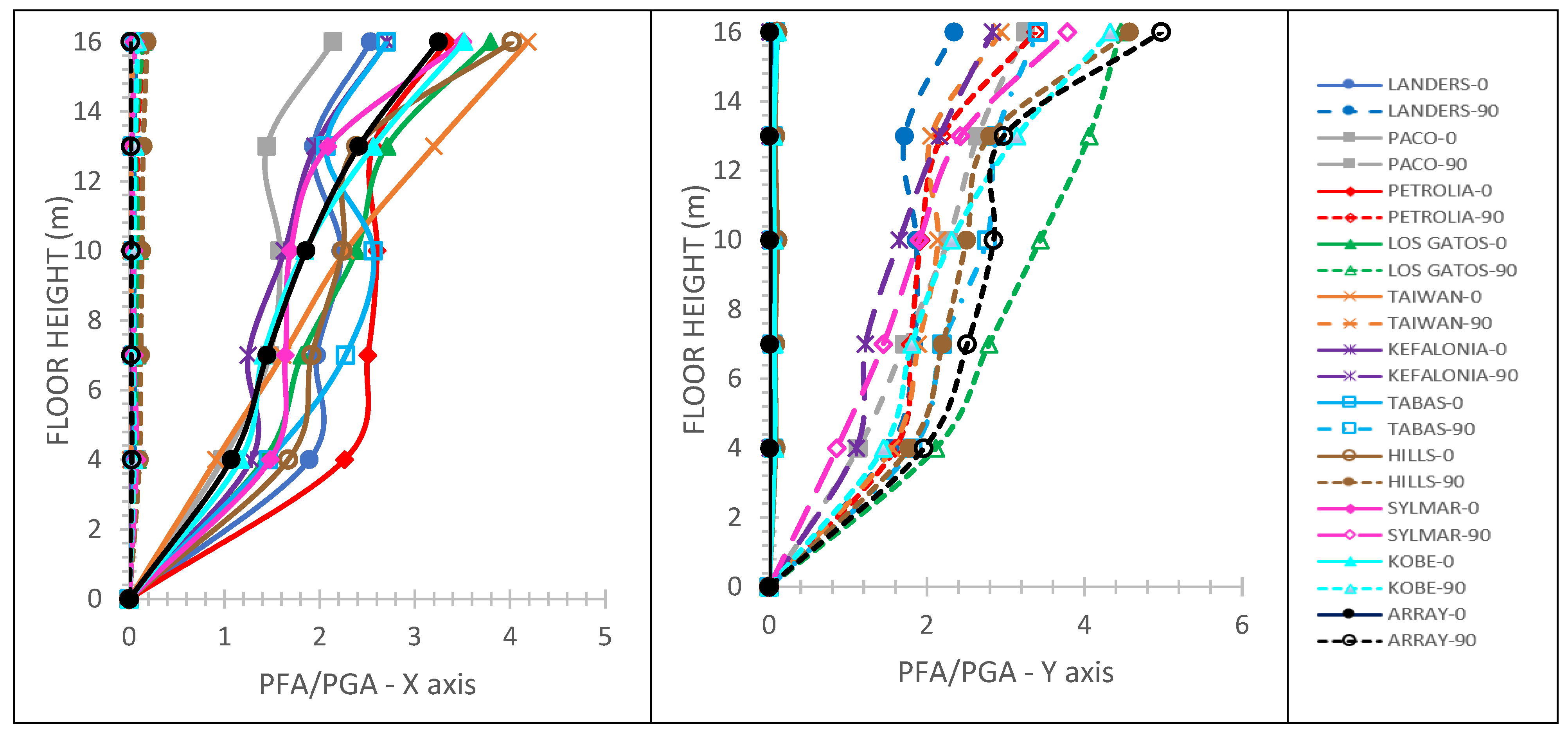
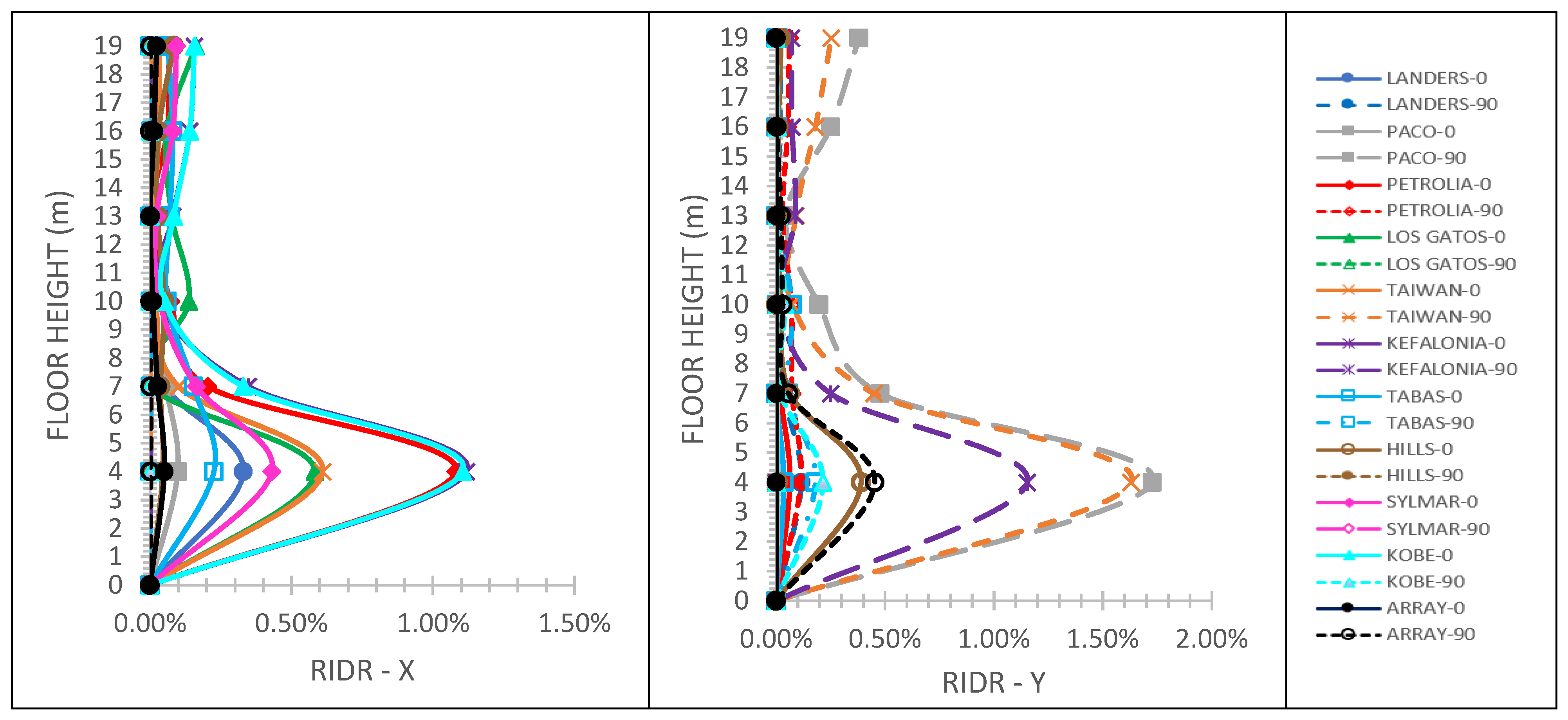
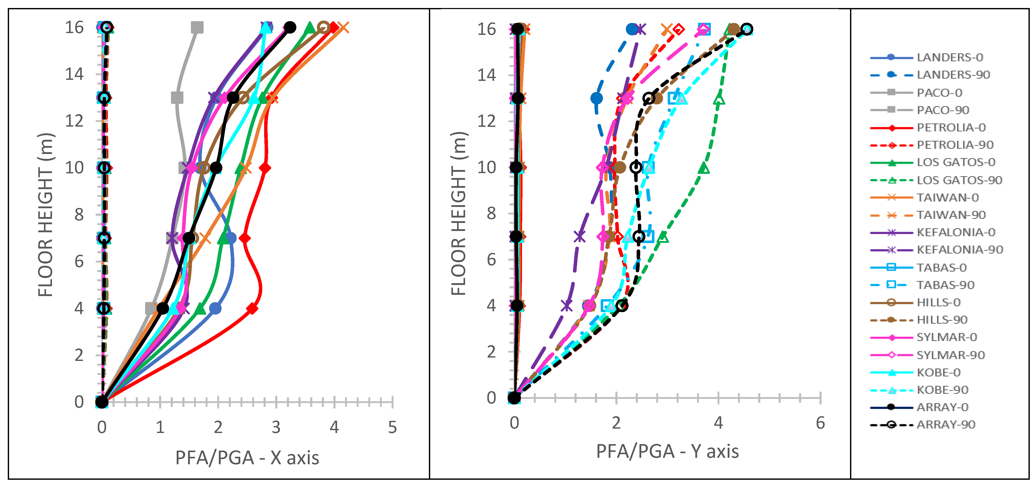
For the five-story mixed building of
Figure 1d, the maximum IDR values computed for the X and Y horizontal directions of the building are 3.02% and 2.18%, respectively, for the case of fixed steel structure to the r/c one, and 3.40% and 2.21%, respectively, for the case of fixed-pinned steel structure to the r/c one.
Figure 15,
Figure 16,
Figure 17 and
Figure 18 display that: (i) the 0.5% RIDR value is violated for nine seismic motions in total (four and five seismic motions along with the X and Y horizontal directions of the building, respectively) for the case of fixed steel structure to the r/c one; (ii) the 0.5% RIDR value is violated for ten seismic motions in total (six and four seismic motions along with the X and Y horizontal directions of the building, respectively) for the case of the fixed-pinned steel structure to the r/c one; (iii) for the X horizontal direction of the building, the maximum PFA/PGA is 4.15 and 4.18 for the cases of fixed and fixed-pinned, respectively, for the steel structure to the r/c one; (iv) for the Y horizontal direction of the building, maximum PFA/PGA is 4.56 and 4.97 for the cases of fixed and fixed-pinned, respectively, for the steel structure to the r/c one.
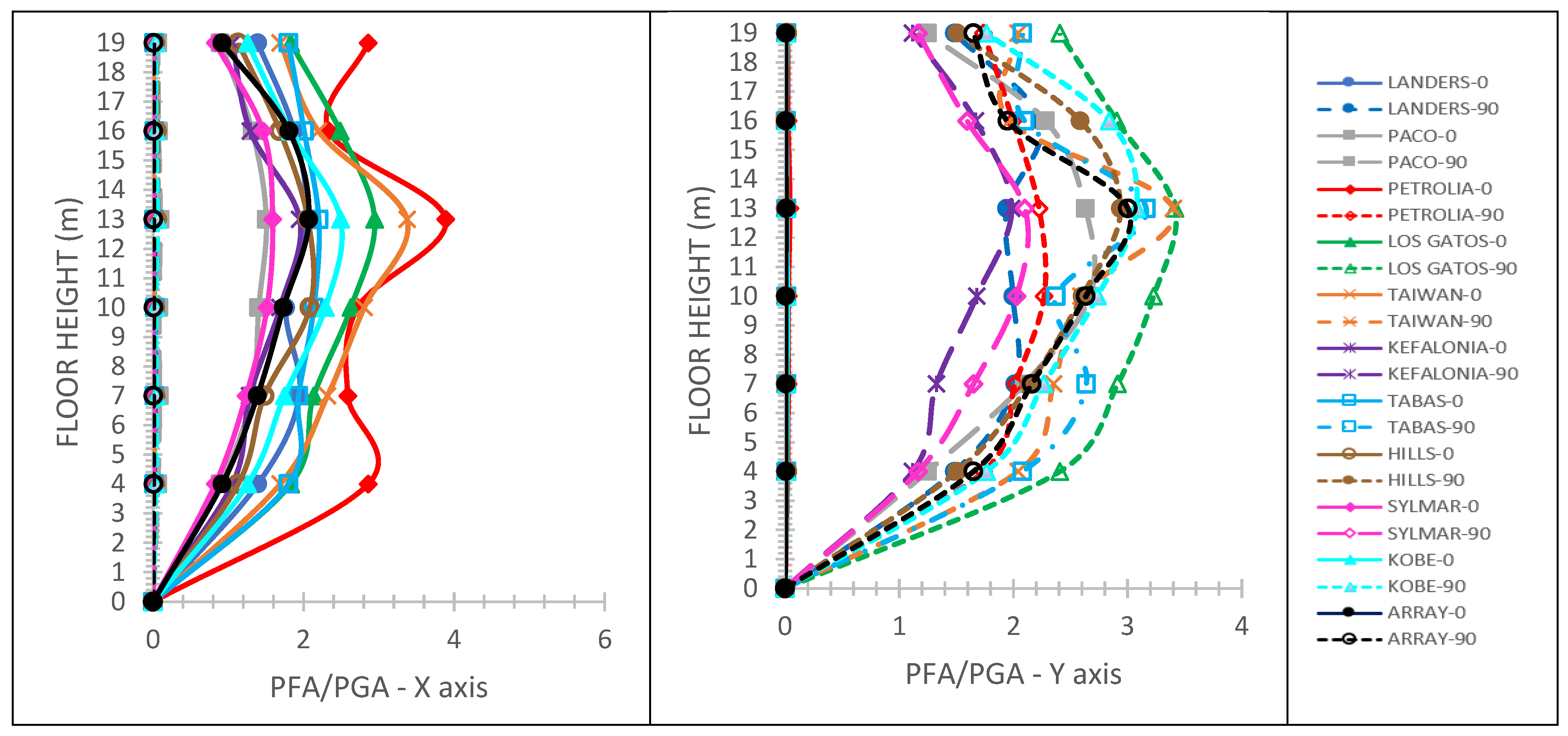
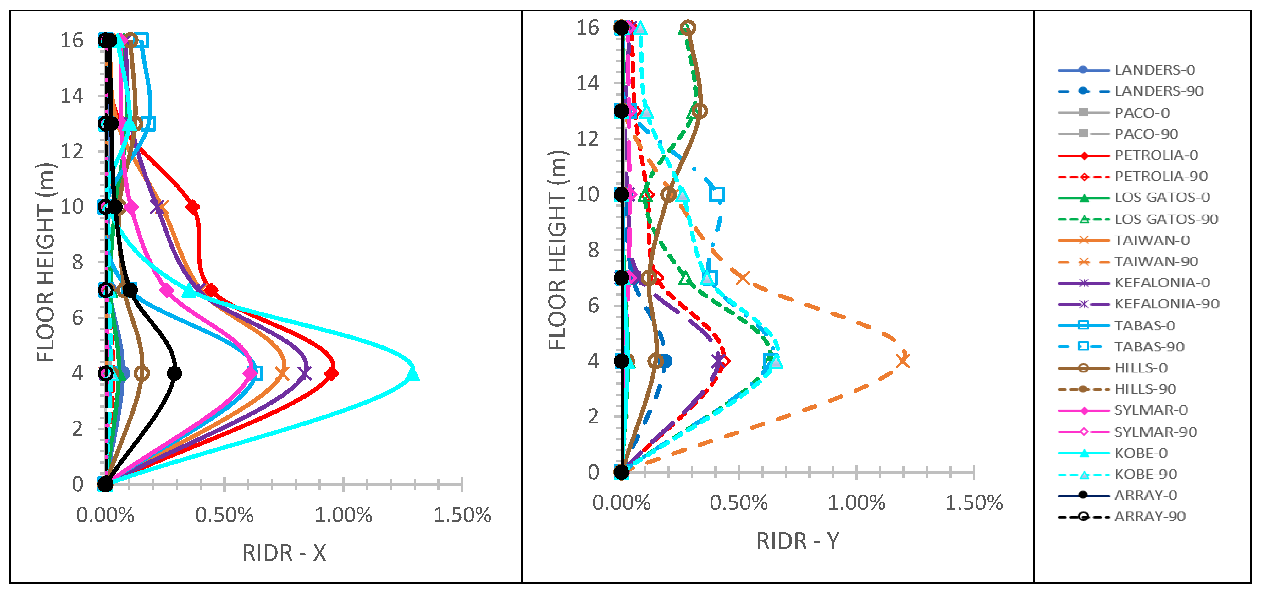
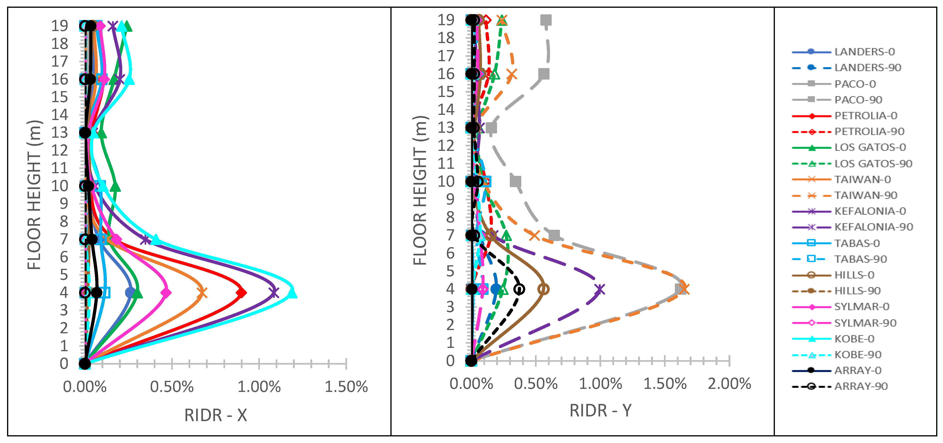
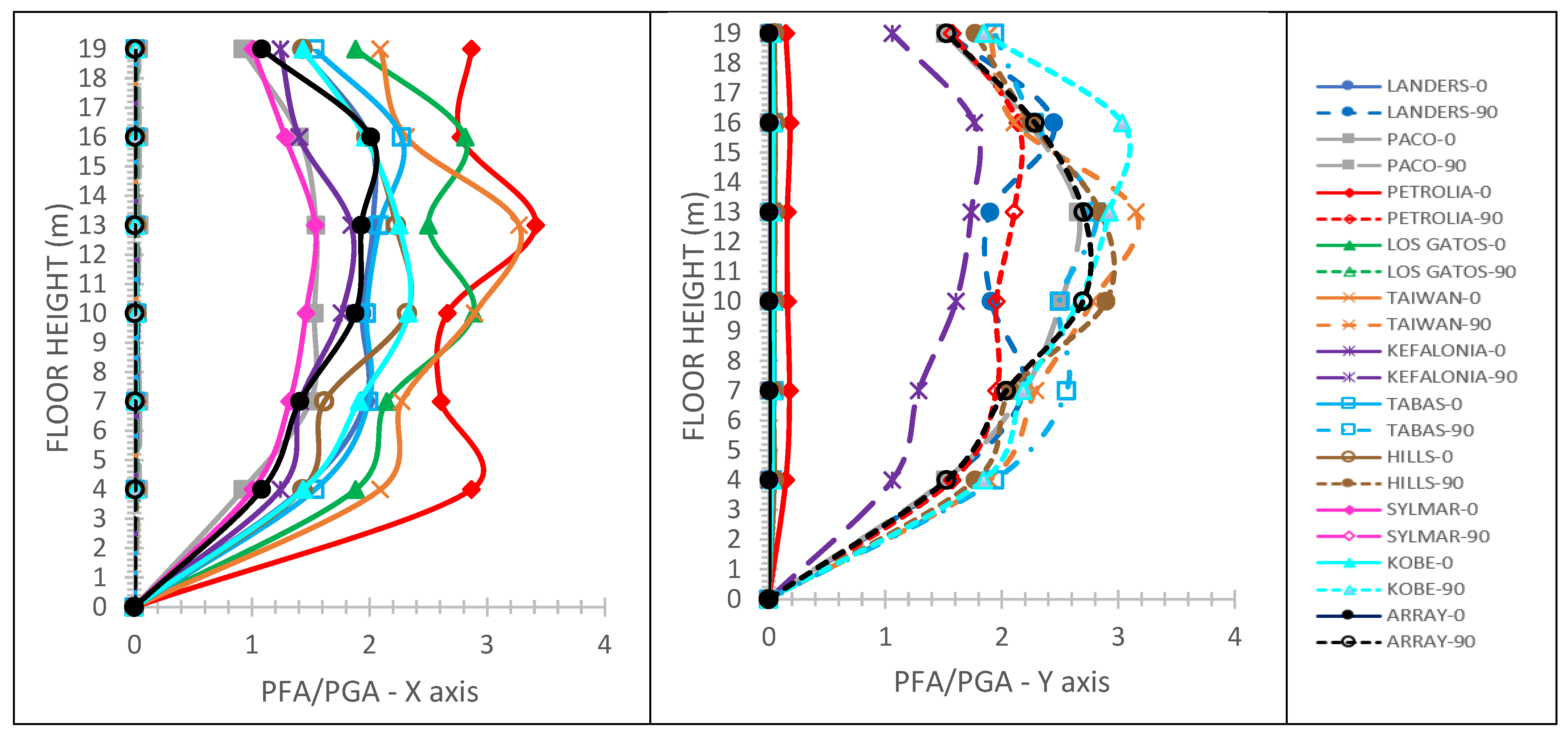
Finally, for the six-story mixed building of
Figure 1e, the maximum IDR values computed for the X and Y horizontal directions of the building are 2.79% and 3.26%, respectively, for the case of fixed steel structure to the r/c one, and 2.83% and 3.04%, respectively, for the case of fixed-pinned steel structure to the r/c one.
Figure 19,
Figure 20,
Figure 21 and
Figure 22 display that: (i) the 0.5% RIDR value is violated for eight seismic motions in total (five and three seismic motions along with the X and Y horizontal directions of the building, respectively) for the case of fixed steel structure to the r/c one; (ii) the 0.5% RIDR value is violated for eight seismic motions in total (four seismic motions along with each one of the X and Y horizontal directions of the building, respectively) for the case of fixed-pinned steel structure to the r/c one; (iii) for the X horizontal direction of the building, maximum PFA/PGA is 3.41 and 3.88 for the cases of fixed and fixed-pinned, respectively, steel structure to the r/c one; (iv) for the Y horizontal direction of the building, maximum PFA/PGA is 3.15 and 3.41 for the cases of fixed and fixed-pinned, respectively, for the steel structure to the r/c one.
Regarding the PFA/PGA plots shown above, it is concluded that this ratio is maximized at the steel part of the mixed building. However, an exception is observed for the six-story mixed building where the maximum value of PFA/PGA occurs at the upper r/c story. On the other hand, the PFA/PGA values at all stories may be small in one of the horizontal directions X and Y. This is justified, as the mixed buildings studied herein essentially respond in this horizontal direction, where the strongest ground motion component is applied.
From the maximum IDR values mentioned above, it is clear that the seismic performance of the three-, four- and six-story mixed buildings lies between the LS and CP levels, whereas that of the two- and five-story ones lies between either the DC and LS or the LS and CP levels. The large (i.e., larger than 2.5%) values of maximum IDR almost always lead to large values of maximum RIDR.
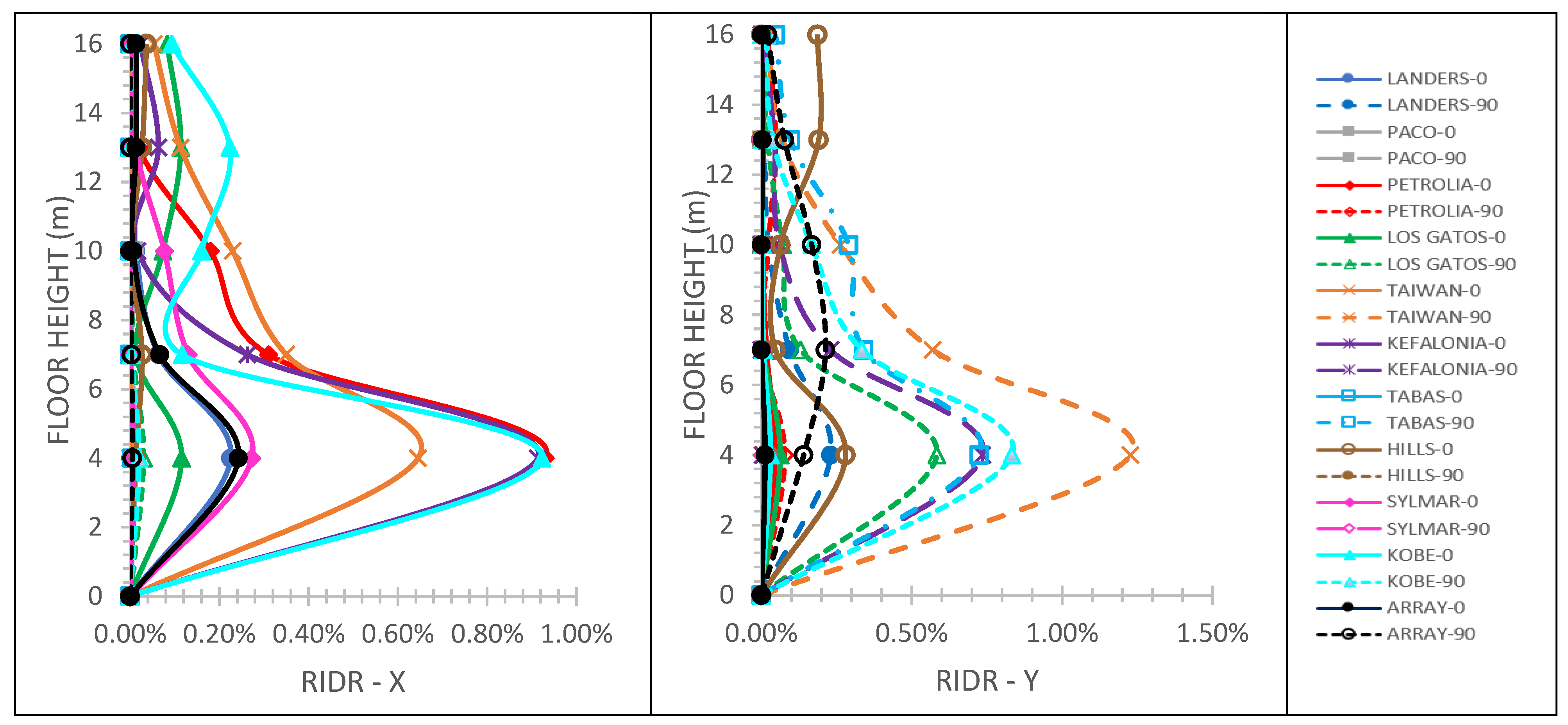
Regarding RIDRs, the relevant plots presented above reveal that the maximum RIDR always takes place at the r/c part of the mixed building. Taking into account the exhibition of large maximum RIDRs, i.e. over the threshold 0.5% value considered, one should check if plastic hinges are formed at both ends of the columns, as this eventually triggers a soft-story mechanism. Indeed, when RIDR surpasses 0.5%, plastic hinges are observed at the top and bottom ends to many columns of the lower r/c stories, whereas columns of the steel stories, with only a few notable exceptions, remain elastic.
Table 5 provides the total number of failures for each mixed building studied herein based on RIDRs larger than 0.5% in conjunction with plastic hinge formation at both ends of the columns. It is recalled that the total number of NLTH analyses performed for each mixed building of
Figure 1, taking into account the support condition of the steel structure to the r/c one, is 22 (see end paragraph in
Section 3).
Judging by the number of failures presented in
Table 5, irrespectively of the support condition of the steel structure to the r/c one, it is concluded that the mixed buildings studied herein, despite being designed by a modern seismic code [
1], are expected to exhibit unfavorable seismic behavior when subjected to near-fault seismic motions. This unfavorable seismic behavior is justified, as explicit seismic design recommendations for building structures located at the proximity of a seismic fault are not provided in [
1].
Based on the aforementioned results and discussion as well as for assessment purposes of other types of mixed r/c-steel buildings, the procedure implemented in this work starts with the design of the r/c and steel parts of the mixed building, continues with the conduction of NLTH analyses under a specific set of seismic motions and ends with the computation of the seismic response indices needed. The maximum values of these indices are then compared with those values that are expected not to be surpassed for a given seismic performance level.
5. Conclusions
The purpose of this paper is to investigate and discuss the seismic behavior of some vertically mixed r/c-steel building structures, as modern seismic codes do not offer specific seismic design recommendations for them. In particular, 3-D numerical models of five realistic and commonly met in engineering praxis r/c-steel mixed buildings are considered.
The seismic response of these mixed buildings, in terms of height-wise distributions of maximum IDR, RDIR and PFA values, is found through NLTH analyses considering near-fault seismic motions and two kinds of support conditions of the steel structure to the r/c one. The r/c and steel parts of the mixed buildings are initially designed as separate structures, following the corresponding seismic design provisions of Eurocode 8 [
1] for r/c and steel structures, but they are then treated as united in the NLTH analyses. Taking into account the maximum values for IDR, RDIR, PFA/PGA and in conjunction with specific seismic performance levels that the r/c and steel parts of the mixed building should satisfy, the following conclusions are drawn:
Near-fault seismic motions induce, as expected, large maximum IDRs and PFA amplifications, which in turn lead to large RIDR.
The maximum values of IDR and RIDR take place at the r/c part of the mixed building, whereas maximum PFA almost always occurs at the steel part.
The large RIDRs are always accompanied by the formation of plastic hinges at the ends of the lower r/c stories, thus rendering the capacity design performed to the r/c part of the mixed building defective.
The steel columns of the mixed building almost always exhibit elastic behavior and, thus, the capacity design performed to the steel part of the mixed building is in all likelihood effective.
The type of support condition of the steel structure to the r/c one does not seem to heavily influence the maximum IDR, RDIR and PFA values induced to the mixed building.
It is finally noted that the seismic response of a mixed r/c-steel building is influenced by the value of the damping ratio assigned to the first few significant modes of vibration. Nevertheless, it is believed that the aforementioned conclusions will not be drastically affected if different values for modal damping ratios, but certainly within the commonly employed values of 2% and 5% for steel and r/c, respectively, are considered in the seismic analyses performed for the purposes of the present investigation.
The findings of this study do not reflect the seismic behavior/performance of mixed r/c-steel buildings having unsymmetrical configurations, along with height and layout or exhibiting differences in stiffness and mass distributions. Nevertheless, symmetrical or almost symmetrical mixed r/c-steel buildings, having probably more stories and/or bay spans, if designed by avoiding drastic changes in mass and stiffness distributions, then their seismic behavior/performance when subjected to near-fault seismic motions is expected to be similar with the one identified herein.
As the mixed, from the perspective of using different materials, type of construction for buildings continues to gain ground in engineering praxis and based on the results and findings of the present study, it is believed that future version of Eurocode 8 [
1] should include specific seismic design guidelines for vertically mixed r/c-steel structures.


