Article

Effect of Chases with Renovation Techniques on the Load Carrying Capacity of Masonry Walls

1
Civil Engineering Department, College of Engineering, The University of Al-Qadisiyah, Diwaniyah 58002, Iraq
2
Department of Mechanical, Aerospace and Civil Engineering, The University of Manchester, Manchester M13 9PL, UK
*
Author to whom correspondence should be addressed.
Infrastructures 2021, 6(11), 160; https://doi.org/10.3390/infrastructures6110160
Submission received: 11 October 2021 / Revised: 3 November 2021 / Accepted: 3 November 2021 / Published: 9 November 2021
(This article belongs to the Special Issue Structural Rehabilitation, Retrofitting and Strengthening)

Abstract

:
Infrastructure through the masonry walls (for example, wiring and piping works) are usually installed using chases in different directions. Introducing these chases in a newly built wall will affect its overall load carrying capacity. However, there has thus far been very limited research into the effects of chases on the response and load carrying capacity of walls. This study has been undertaken to evaluate the structural behaviour of new masonry walls having chases in both horizontal and vertical directions and subjected to compression load throughout an extensive experimental programme. In addition, two renovation techniques have been proposed to infill the chases created in small scale walls (wallettes). The first technique involved the use of plastic wire mesh and cement mortar, while the second incorporated using galvanized steel channel together with the plastic wire mesh and cement mortar. Furthermore, a reference case of wallette without chases has been considered to enable reasonable comparisons to check the effect of the chases and the efficiency of the proposed renovation techniques. The outcomes of this study were used to modify the design equations proposed in the relevant codes of practice. The obtained results showed a notable reduction in the load carrying capacity of the masonry wall due to the introduction of the chases with a reduction percentage of 29% compared to the masonry wall without chase. The percentage decrease depends on the depth of the chase and the inclination angle of the load flow. The walls with horizontal chases exhibited more reduction in the load carrying capacity compared to those with vertical chases. The adopted renovation techniques using galvanized steel channel and/or plastic wire mesh with cement mortar recovered 55% and 93% of the lost load carrying capacity due to the presence of the chase and the failure was due to the de-bonded phenomena of the infill materials. Suitable factors of safety have been proposed to be incorporated in the compressive strength and modulus of elasticity formulas of the masonry walls of the BS EN codes.

1. Introduction

Masonry walls are the oldest structural elements that have been used with the first emergence of civilization [1]. Since its essential components are easily produced from the available raw materials, it kept the momentum of the construction field ongoing. During the past centuries, the configuration of the masonry walls showed many developments starting from the upgrading of its components followed by improving the traditional construction techniques [2,3].
In modern buildings, the installation of the infrastructure services is usually performed in an invisible way which in turn needs cutting of chases in new masonry walls. For instance, electrical wiring, plumbing piping and AC ducts connections require holding them through suitable chases. The direction of the chases varies according to the path adopted for the infrastructure. However, chases are commonly created in either the horizontal or vertical direction in the face of a new masonry wall. Introducing chases in a newly built wall represent a weakness point in its overall integrity. However, limited research works have been focused on the issue of chases in the masonry walls, and the most important published studies stated that the load carrying capacity reduced with a ratio up to 28.5% for the case of vertical 38 mm wide and 25 mm deep chases [4]. In their experimental work on wall samples containing horizontal or vertical chases, Kirtschig and Metje [5] concluded that the reduction in the load carrying capacity is related to the decrease in the cross-sectional area. Despite most of the available codes of practice mentioned for the general instructions in the case of introducing chases [6,7,8], attempts for indexing the strength reduction due to the chases was made by Sahlin [9]. Similar to the former attempt with a similar research approach, the European Masonry Code ENV 1996-1-1 [10] presented the obtained experimental results in a form of tables including the permissible geometry of chases that can be used without additional verification of the load-bearing capacity.
Recently, Mojsilovic [11] performed extensive experimental investigations of the effect of chases on the structural behaviour of three series of masonry elements with a wall thickness of 150 mm and 175 mm under compression loads. The created chases were 45–50 mm deep and 35 mm wide and they were cut off in three directions: horizontal, vertical and inclined. Three infill materials were used gypsum, cement mortar and high-strength mending mortar. Based on the obtained results, a reliable truss model was suggested to explain the load flow in the chase zone. It was noted that both gypsum and cement mortar infills had minimal effects on the reduction of compressive strength of the masonry elements. On the other hand, the hard and more stiff infill material of high-strength mending mortar showed a notable influence in eliminating the reduction of the strength of the masonry walls.
In a recent research study, Milani, et al. [12] noticed a significant drop in the load carrying capacity of the masonry walls due to any kind of chase even if the depth of cutting is small (20% of the wall thickness). Consequently, they recommended avoidance of such cutting in the installation of the infrastructure works.
In order to have a clearer understanding of the critical effect of the chases and the role of the available modern techniques in reducing the effect of chases, more research work is needed. Consequently, the present study has been conducted to evaluate the structural behaviour of clay brick masonry walls with chases in both horizontal and vertical directions under the effect of the compression loads. In addition, two renovation techniques were considered to infill the chases. The first technique involved the use of plastic wire mesh and cement mortar, while the second incorporated a galvanized steel channel together with the plastic wire mesh and cement mortar. For the purposes of comparison, a reference wall sample (without chases) was also tested. The comparison was made based on the load-deformation criteria in addition to monitoring the failure modes. As an outline for this paper, Section 2 presents the details of the experimental programme which includes material used, properties of cement mortar, formulation of the masonry wallettes, creation of the chases and method of the test and measured parameters. The obtained results from the experimental programme are shown in Section 3, followed by their discussions in Section 4. Finally, Section 5 summarizes the main conclusions of this study.

2. Experimental Programme

The experimental programme has been designed to enable understanding the effect of the chase direction on the behaviour of masonry walls under compression loading and to evaluate the suggested techniques to eliminate/reduce the loss of load carrying capacity caused by the chasing. Consequently, the contents of the experimental programme are materials used, construction of small-scale walls (wallettes), method of the test and the measured parameters.

2.1. Material Used

In this study, solid clay bricks locally produced in Iraq were used as masonry units with nominal dimensions of 24 cm × 12 cm × 7 cm. Both compressive strength and absorption aspects were measured using ten brick samples, as shown in Table 1, and they were within the limitations of Type C as per the Iraqi Standards No. 25-1998 [13]. The total absorption has been measured firstly as a percentage increase in the sample weight when immersed in water for 24 h to the air-dry weight. The compressive strength test was then conducted using a digitally controlled compression machine with a maximum load capacity of 2000 kN. A constant loading rate of 0.3 MPa/s was used throughout the test. The value of the compressive strength was determined as the maximum failure load divided by the surface area subjected to the compression load. Portland cement was used to create cement mortar which is required to lay the brick units and render the wallettes. It was compliant with the EN BS 197-1 [14]. Locally available natural sand was used as a fine aggregate. It has particle size distribution complying with the BS 882:1992 [15]. High-density polyethylene mesh with 10 × 10 mm square openings and 0.5 mm wire thickness in addition to galvanized steel channel with dimensions of 5.5 × 5 × 0.1 cm were used to renovate the fabricated chases, as shown in Figure 1. The weight of the plastic wire mesh was 175 gm−2, while the tensile strength of the galvanized steel channel was 270 MPa.

2.2. Properties of Cement Mortar

The cement mortar was formulated using 1:3 (cement: sand) as a volume ratio with 0.7 W/C to have suitable workability during the work. Three 50 cm cubed samples were cast for each series of tests and cured in water to determine the compressive strength of cement mortar at 28-day age. The average value of the measured compressive strength was 10 MPa, so this cement mortar is classified as M10 according to the BS 5628-1 [16].

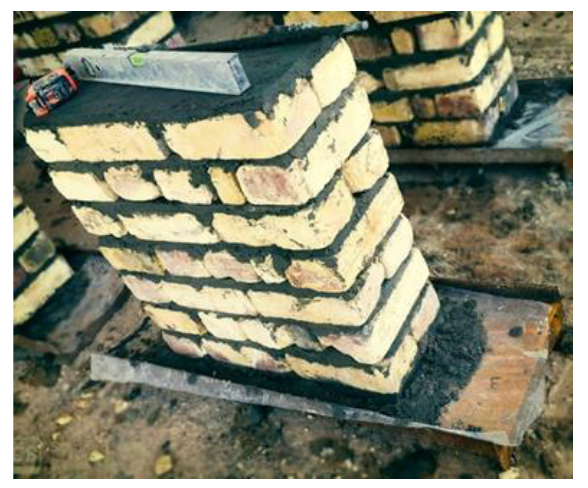
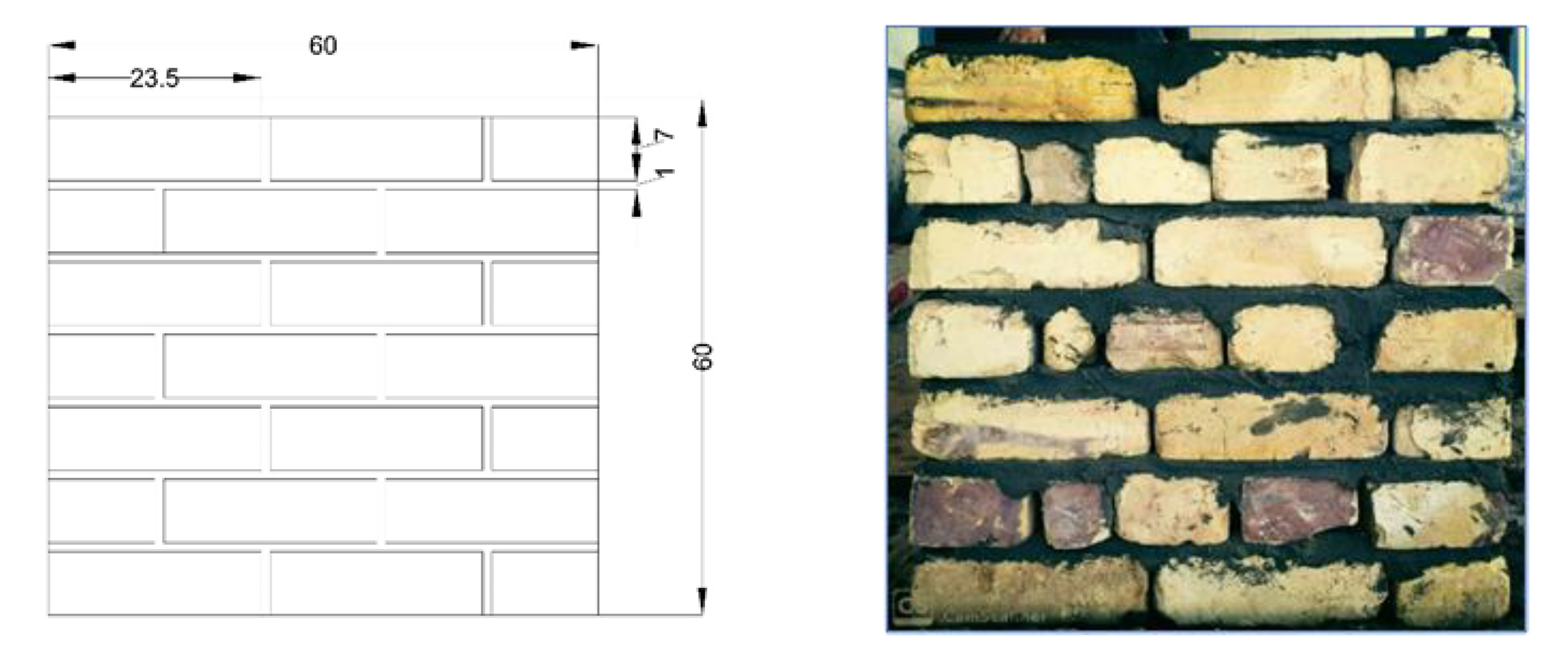
2.3. Formulation of the Masonry Wallettes

For practical considerations, BS EN 1052-1 [17] mentions the possibility of using small scale walls (wallettes) in the experimental investigation in order to evaluate the structural behaviour under the effect of different loading conditions. The aforementioned standard stated also that more than 0.04 m2 are needed for reasonable replication of the large-scale masonry walls. Thus, more than 0.04 m2 was provided throughout the construction of one leaf wallettes. The latter has 60 cm width (two and a half brick length), 60 cm height (7 brick courses) and 24 cm thick (one brick length), as shown in Figure 2. In all wallette samples, the thickness of the cement mortar was kept constant at 1 cm. For ease of lifting, the wallettes samples were built upon a thick steel plate and the upper surface was finished with cement mortar to have one level in order to avoid the concentration of loading and to achieve a uniform distributed load, as shown in Figure 3.

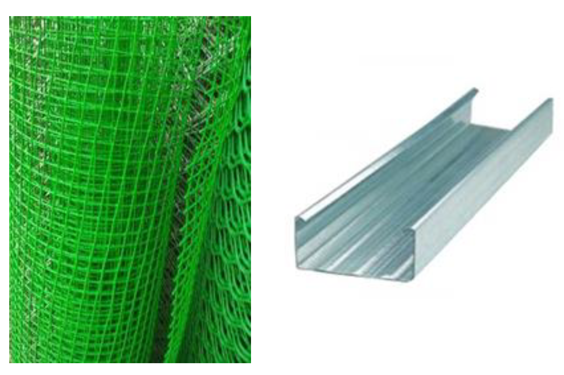
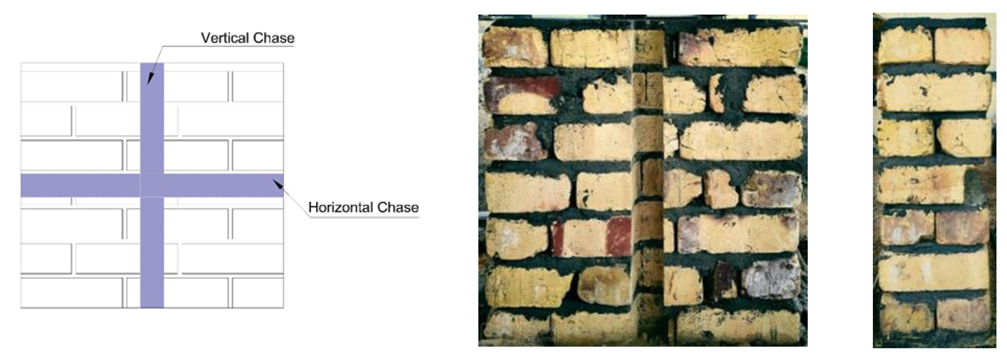
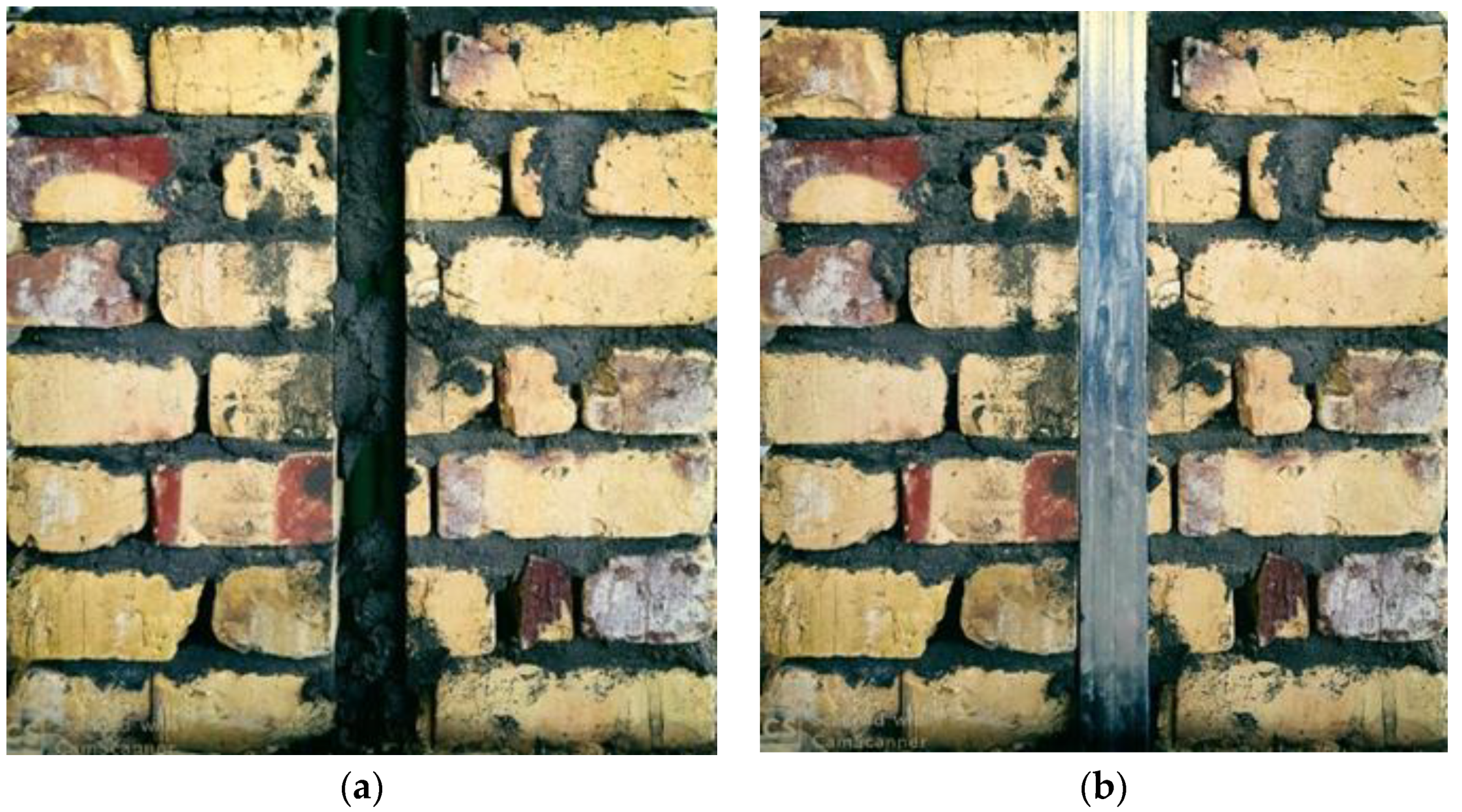
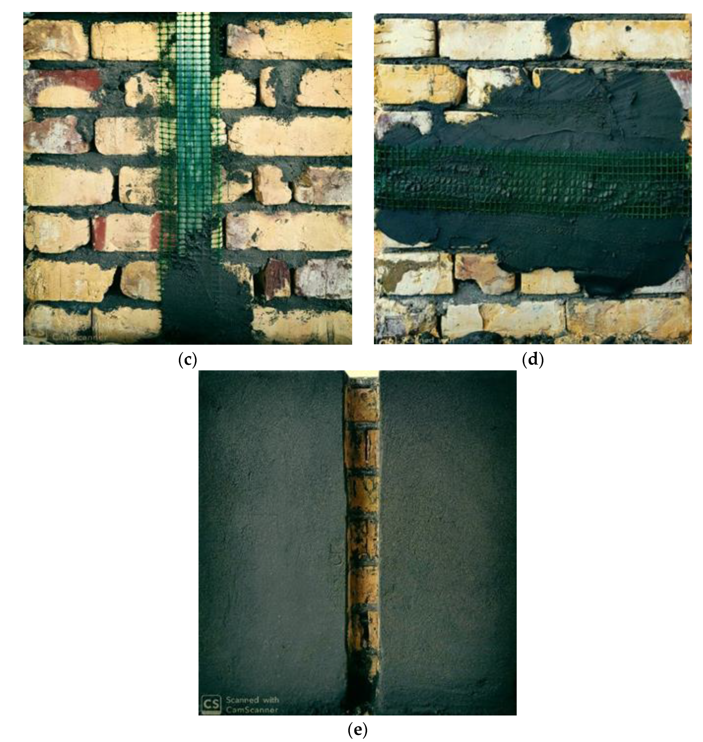
2.4. Creation of the Chases

After 28 days, vertical and horizontal chases were created in the front face of the wallettes using a special clipper-diamond tipped cutting wheel. The chases have width and depth of 5.5–6 cm and they were continued along the width or height of the wallettes. For the purpose of comparison, a reference wallettes sample without chases was also formulated. Before the time of the test, all of the investigated samples were rendered with a 1 cm cement mortar layer. For the renovated wallettes samples, plastic pipes were firstly inserted in the formulated chases to simulate the infrastructure of plumbing or electrical works. Plastic wire mesh with cement layer or galvanized steel channel followed by plastic wire mesh with cement layer was then applied to cover the whole chases with an offset distance of 5 cm from the outer edges of the chases, as shown in Figure 4.

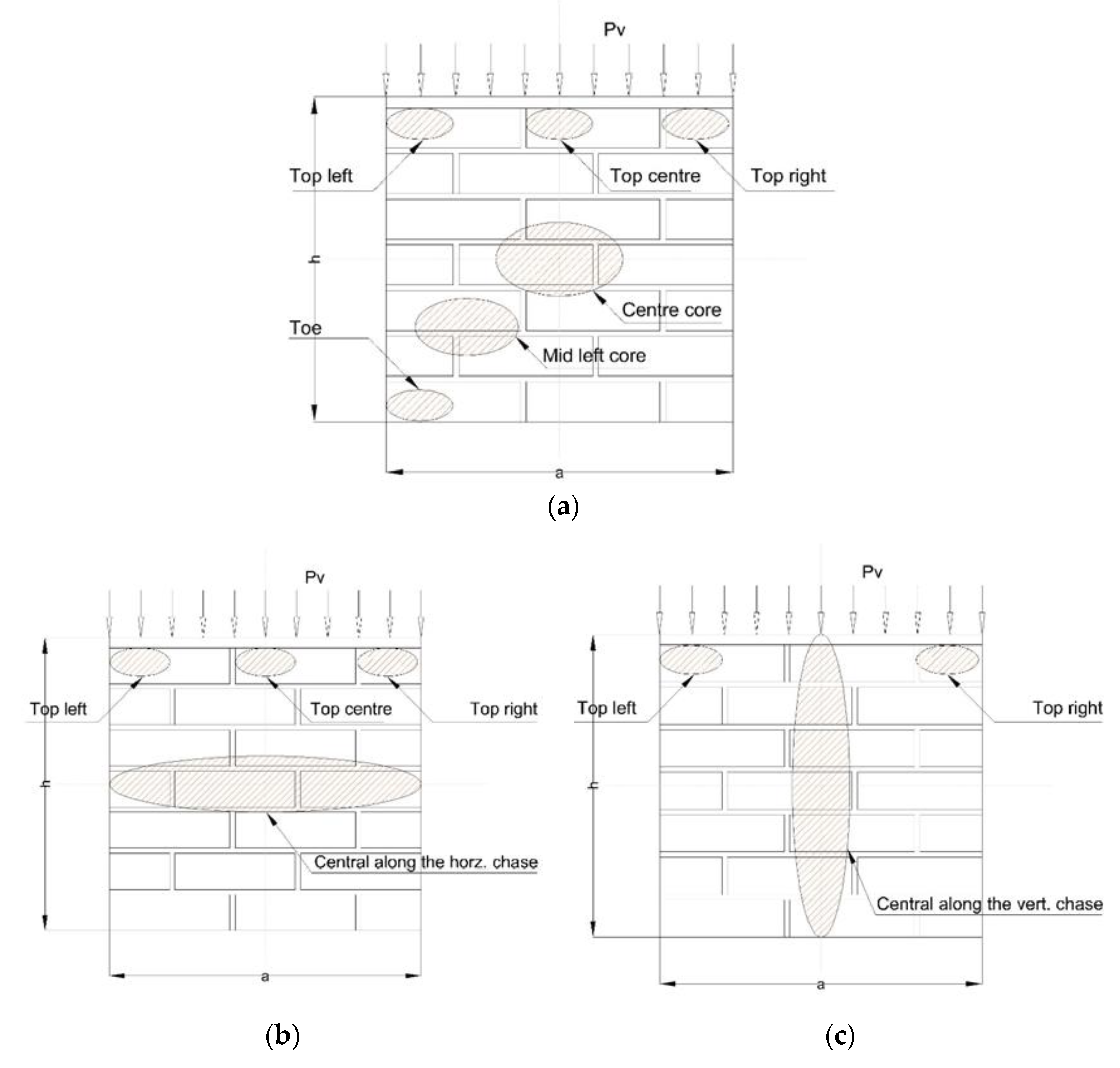
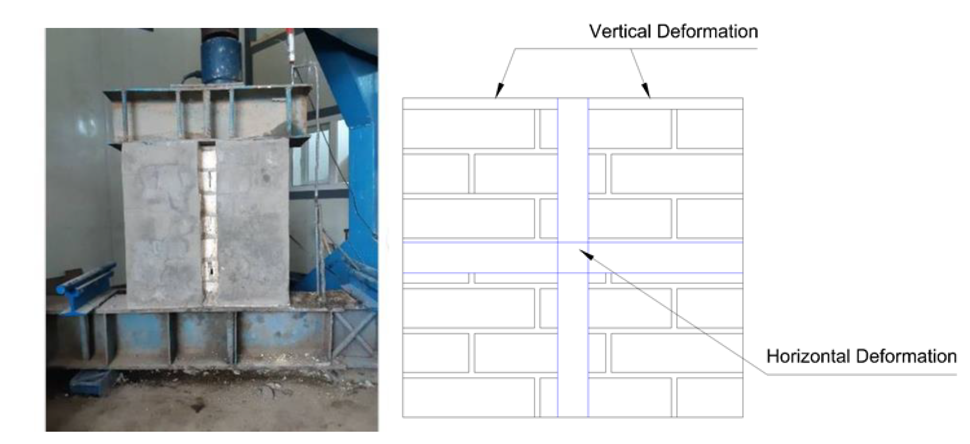
2.5. Method of the Test and Measured Parameters

The methodology of the test focused on the performance of newly built masonry elements subjected to compression loads when introducing the chases. On this basis, the experimental programme comprises testing three groups of wallettes. The first group is considered as a control sample which is adopted for the purpose of comparison. The second group consists of chases in the horizontal direction (along the width of wallettes), while the third group have chases in the vertical direction (along the height of the wallettes). Both of the second and third groups were designed with three options: open chases, chases renovated with plastic wire mesh and cement layer and chases renovated with galvanized steel channel together with plastic wire mesh and cement layer, as shown in Figure 5. For all of the tested samples, the measured parameters are the load-vertical and lateral deformations in addition to monitoring the failure modes. The average test results of two wallette samples was considered for each case. The locations of the measured deformations in terms of displacements were at the top surface and the middle front face of the wallettes using linear potentiometers. A universal steel rig connected to load cell with capacity of 2000 kN was used in the test. The load-displacement data were digitally recorded using a datalogger in kN and mm units, respectively, as shown in Figure 6.

3. Results

The obtained results of the load-deformation features for wallette samples containing horizontal and vertical chases in addition to the reference samples (i.e., wallette without chase) are shown in Figure 7, Figure 8, Figure 9 and Figure 10. Figure 11 shows the statistical variation in the values of the ultimate load measured for the wallette samples containing horizontal chases using error bar feature.

4. Discussion

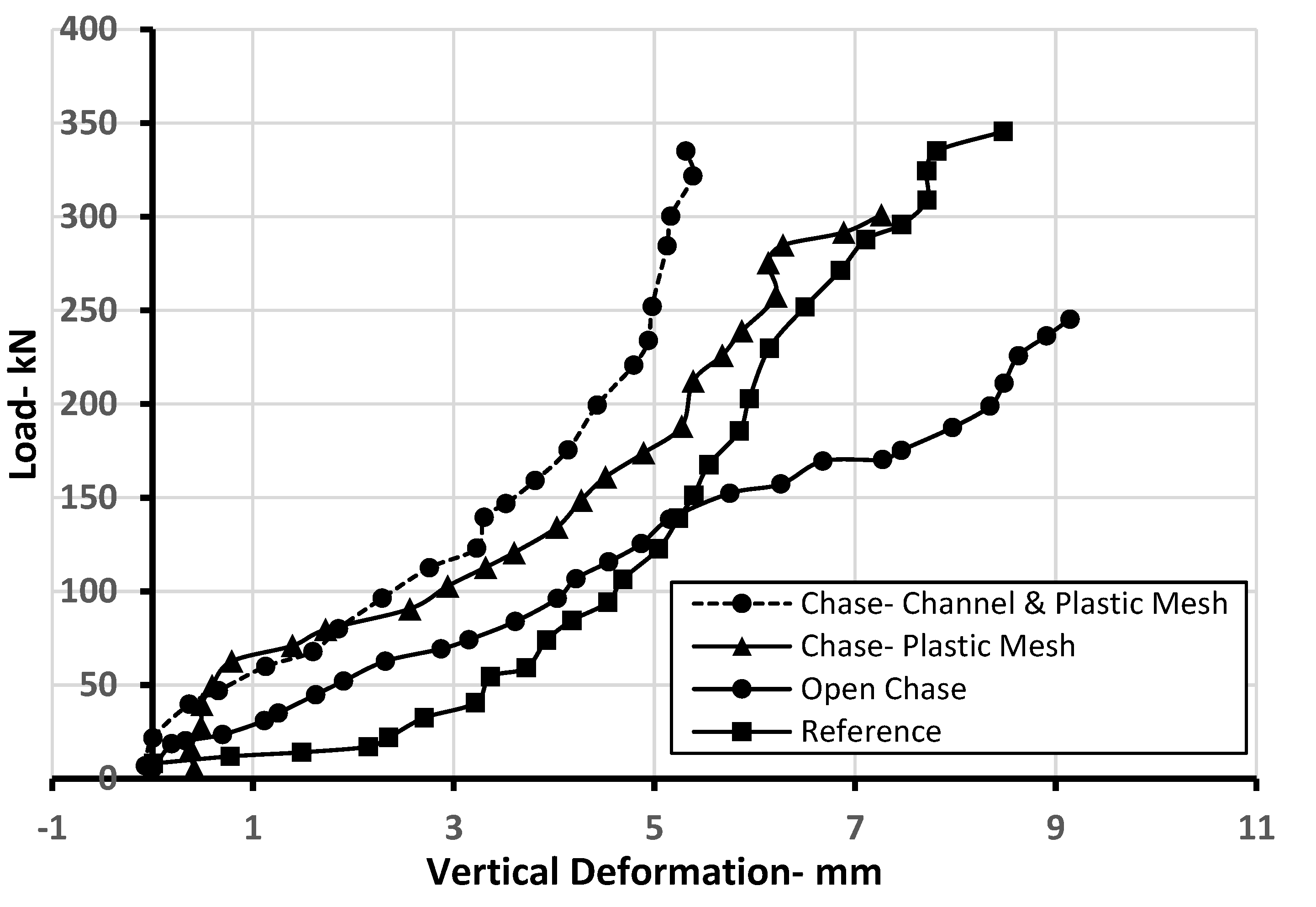
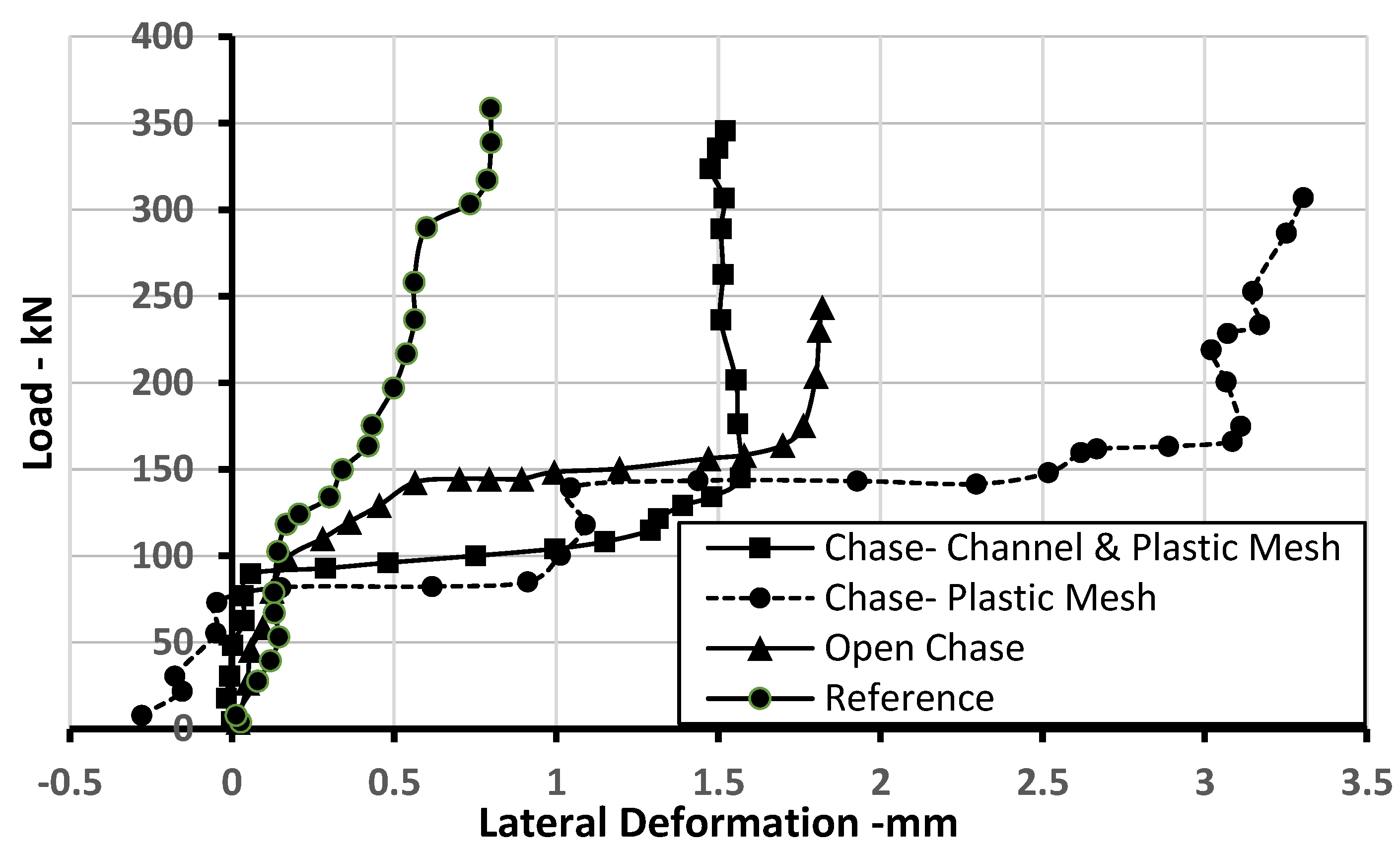
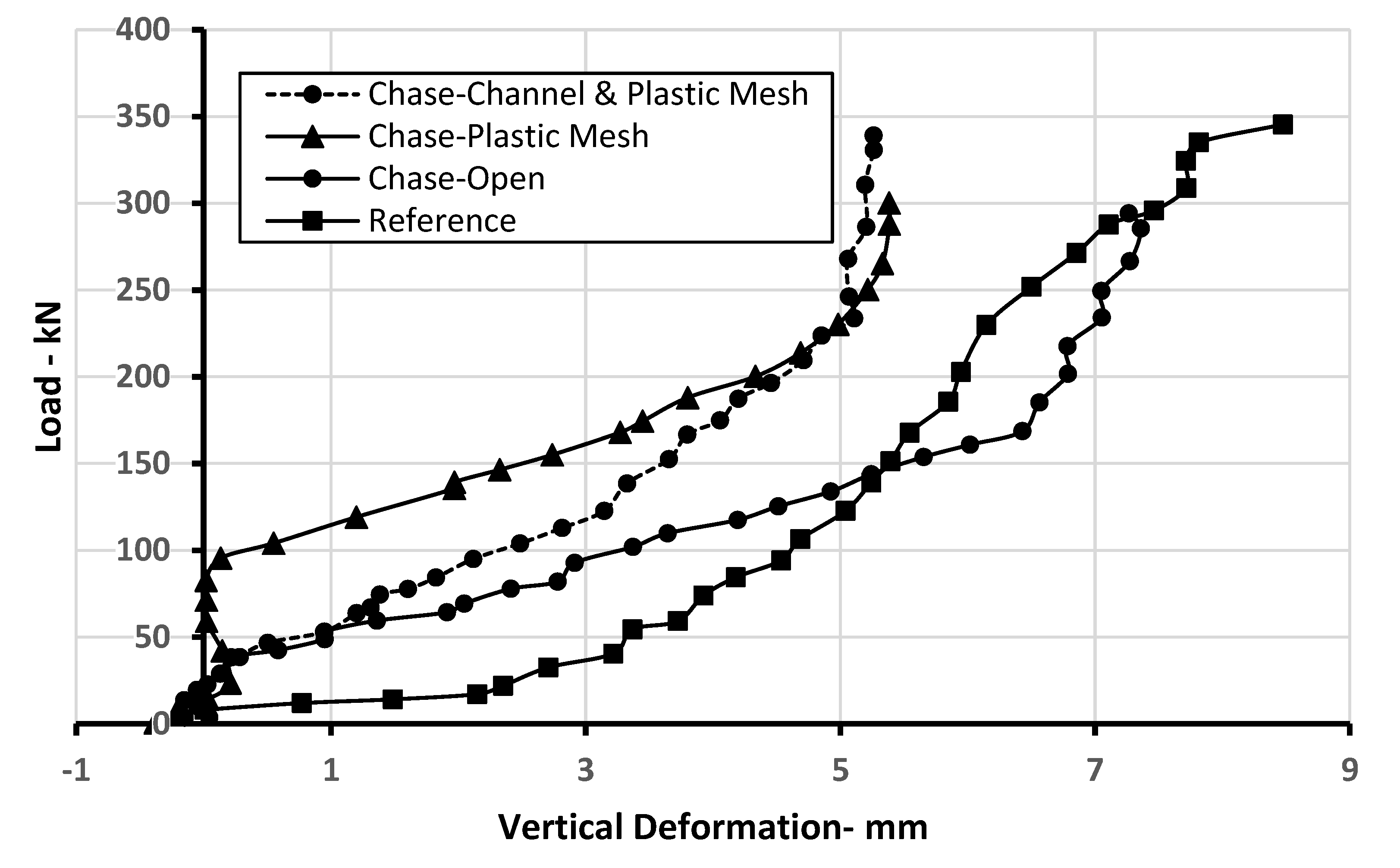
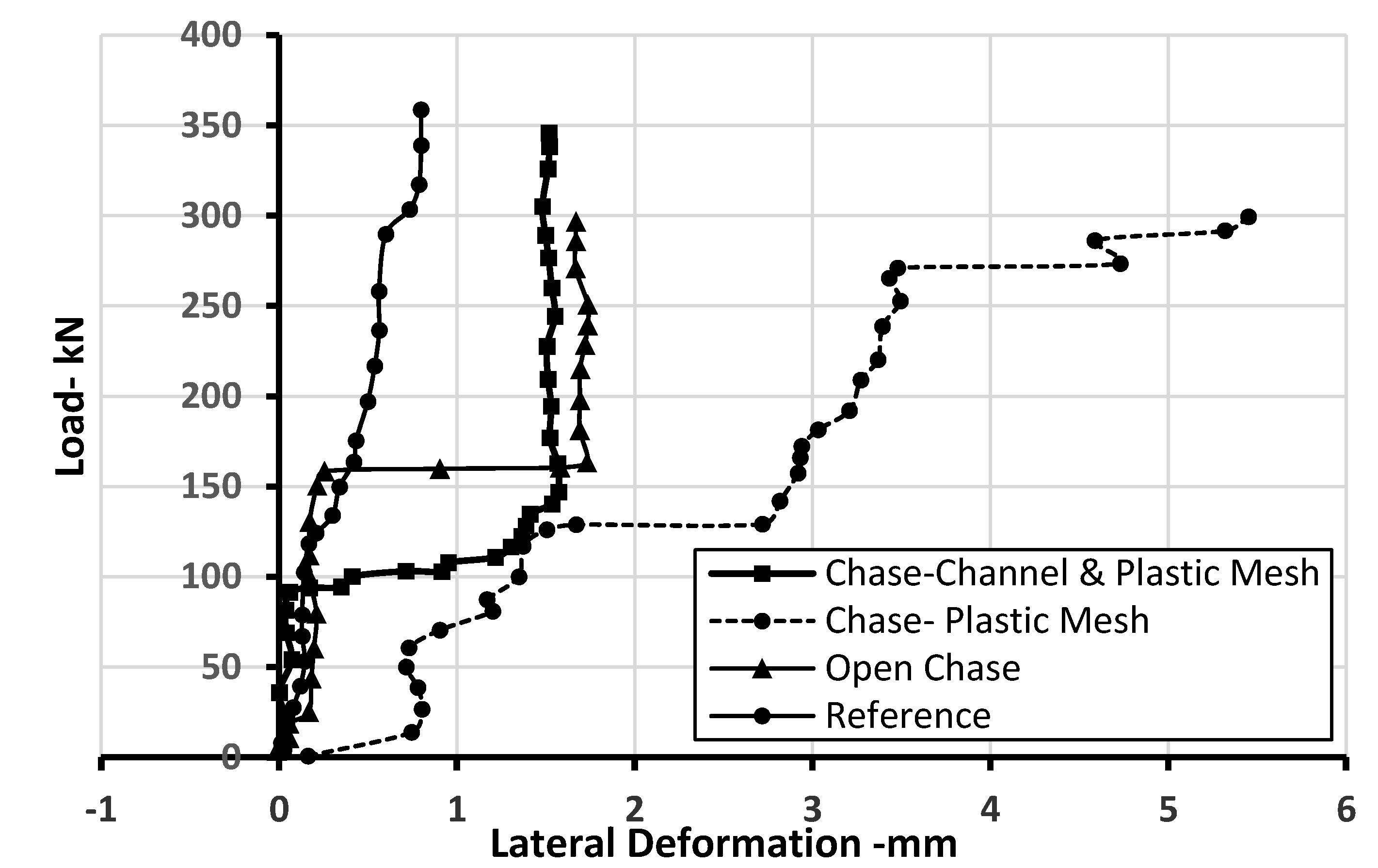
4.1. Load- Deformation Behaviour

Figure 7, Figure 8, Figure 9 and Figure 10 clearly show the effect of the created chases in both directions on the ultimate failure load of the wallettes. The recorded ultimate load for the reference sample was 345 kN. This level of load capacity reduced sharply to reach 250 kN (i.e., percentage reduction of 29%) due to the present of open horizontal chase at the middle height of wallette. Such reduction was associated with more deformation characteristics in both vertical and lateral directions, as shown in Figure 7 and Figure 8. This was expected as the horizontal chase represents the weakness region which accommodates more stresses than the other regions of the wallette elements. Consequently, stresses concentration will take place at this zone result in a triaxial action exceeding the load carrying capacity of the wallette. Such attitude promises for more deformations in the available spaces. However, at a load level lower than one-third of the ultimate load, less vertical deformation was noted for the wallette samples containing open chase compared with the reference sample. Such behaviour may be attributed to the redistribution of load flow over the subjected area which is mainly governed by the depth of the chase. After the former strength level, more vertical deformation was obtained. In this regard, Mojsilovic [11] suggested a truss model to predict the force flow along the compression sections with horizontal chase. He observed that the failure is dominated by the tensile capacity of the masonry and it was dependent upon the angle of inclination ( θ ) of the inclined truss member resulting from the horizontal chase. This means, the deeper chase exhibits steep inclination and rapid failure will take place.
The use of plastic mesh and cement mortar as a renovation technique for the chases recovered the reduction in the load carrying capacity of the wallettes. As can be seen, the ultimate load at failure reached 306 kN with the use of the former technique. This forms 86% of the original load capacity of the reference wallette sample, meaning that 55% of the lost bearing capacity due to the open chase was recovered. This can be explained by the filling role of the plastic mesh and cement mortar and their adhesion to the chase surfaces. Such filling techniques provide more rigidity to the wallette system and works as disconnector for the tension lines of the inclined trusses. Thus, it was expected to have lower vertical deformation and the de-bonded failure will govern the structure behaviour under compression loading, as shown in Figure 7.
Using galvanized steel channel together with plastic wire mesh and mortar was an active renovation technique for counteracting the adverse effect of the horizontal chase. It was found that 98% of the ultimate failure load can be achieved and the value of load carrying capacity reached 340 kN. High stiffness and more ductile characteristics were the reasons for the final behaviour of this kind of renovation. In addition to the filling role, such composite material will support overall load bearing capacity and restrain the vertical deformation, as shown in Figure 7, where only 5 mm vertical displacement was recorded. Basically, the aforementioned behaviour is defined as a reinforcement action that enhances the tensile strength of the wallettes. Based on the adhesion capacity at the interfacial surfaces between the galvanized steel, plastic wire mesh and cement mortar with the interior surfaces of the chase, the failure will propagate as a debond phenomenon.
For the case of the lateral deformation shown in Figure 8, all of the tested samples revealed more lateral displacement than that of the reference wallette. The largest deformation was noted for the wallettes renovated with plastic wire mesh and cement mortar at 3 mm out of plane. This behaviour may be attributed to the nature of vertical confinement of the compression load which tends to produce lateral pushing for the regions far away for the constrained ends, i.e., mid height of the wallette. Due to the discontinuity of the wallette system, the less ductile filler of the chase shows more de-bonded behaviour and skip away out of the wallette plane. Such justification is acceptable for the case of galvanized steel channel together with plastic wire mesh filler where more ductility is available and less lateral deboned is expected. However, due to the heterogenous nature associated with the renovation technique, all of the measured cases exhibited higher lateral deformation than the reference sample which seem to be more homogenous than the others
A similar tendency for the wallettes with horizontal chases was noted for those containing vertical chases in terms of load-vertical and lateral deformations, as shown in Figure 9 and Figure 10. However, a slight increase in the value of the load carrying capacity was observed for the samples tested with open chase. As the direction of the cavity located within the compression region, less reduction in the load carrying capacity occurs. The percentages decrease for the cases of open chase, chase containing plastic wire mesh and chase containing galvanized steel channel together with plastic wire mesh and mortar compared with the reference wallette sample were 15%, 13% and 2%, respectively. Similar results were also noted by Mojsilovic [11].
Except for chase containing plastic wire mesh with cement mortar, the lateral deformation did not exceed 2 mm. The former case exhibited the highest lateral displacement at 5.5 mm, as shown in Figure 10. The justification presented for the horizontal chases is still valid and can be applied to explain the structural behaviour for the case of vertical chases.
It is worth mentioning that all of the tested wallettes having horizontal or vertical chases showed horizontal jump in the lateral direction. Except for the sample of open chase, this jump was noted at the level of one-third of the ultimate load carrying capacity of the wallette. This strength level considers the critical load value to deboned the infill materials. For wide range of homogenous and semi-homogenous materials the former strength level is the base for calculating the modulus of elasticity as the linearity feature is valid. The maximum jump distance was about 2 mm, as shown in Figure 8 and Figure 10. After this load level, the wallette samples will continue supporting the imposed load and more bowing will be obtained.
From a statistical point of view, Figure 11 gives an indication for the reasonable variation in the measured values of the ultimate strength, so they are valid for the comparison purposes.

4.2. Failure Modes

Figure 12a–e illustrates the main critical regions of the wallettes’ failure modes of the tested samples under axial compression load. Six different critical locations were observed for the intact sample, they were top left, top centre, top right, centre core, mid left core, and toe of the wallette, as shown in Figure 12a. This is indicative of a uniform compression failure mode along the whole body of the wallette. In contrast, the wallette sample incorporated horizontal chases, crack propagation was noted along the direction of the chase followed by crushing of the upper parts of the wall, as shown in Figure 12b. In a similar manner, the wallette incorporated vertical chase showed cracks starting from the upper contact area and passes through the chase. When the system becomes unstable, localized edge crushing will take place at the top left and top right of the wallette, as shown in Figure 12c. As mentioned before, de-bonded failure modes were noted during the tests for both the galvanized steel channel and the plastic wire mesh and mortar. After the occurrence of the de-bonded phenomenon, the contribution of the infill materials in supporting the imposed loads reduces and they work as separated elements due to the less connection with the masonry surfaces. However, more lateral bowing was noted combined with surface fracture at the top centre, top left and top right of the wallettes prior the complete failure, as shown in Figure 12d,e. It can be seen that the present of the chases and the infill materials produce non uniform compression failure mode for the tested wallettes. For other parts of the wallettes not containing chases, the mechanism of failure was explained by occurrence of a biaxial tension on the both sides of the bed cement mortar joint. Since the applied load is compression in nature, the interaction of the biaxial tension-axial compression stresses reaches the failure envelope. Consequently, vertical cracking through the brick units occurs [18,19].

4.3. Comparison with the Constitutive Formulae Given in Codes of Practice

Table 2 shows a summary of the results obtained from this experimental investigation including calculating the compressive strength of the masonry wallettes, modulus of elasticity and the end vertical and lateral displacements. The values of the modulus of elasticities were calculated based on the measured compressive strength of the wallettes using the suggested expression by BS ISO 1920-10 [20], as per in Equation (1).
E c = σ ε = σ a σ b ε a ε b
where σ a = f c / 3   and σ b = 0.5 .
It would be interesting to explore the applications of the obtained results by comparing them with generalized formulas presented in the relevant code of practice. In this regard, Eurocode 6 [10] proposed Equation (2) to be used for predicting the value of modulus of elasticity which can be adopted for the purposes of structural analysis of masonry walls.
E = K E f k
where K E is a constant with a proposed value of 1000 and f k is the compressive strength of the masonry wallette. Moreover, BS 5628-1 [16] indicated that the suitable value of K E that suite most of the masonry applications is 700.
In comparison with the results presented in Table 2, none of the aforementioned values suggested for the K E match with the calculated values of the modulus of elasticity, and an overestimation will be achieved when they are applied. On the other hand, the boundary conditions of this study revealed that the value of K E for the reference masonry wallette is within the range of 40.
In terms of the constitutive compressive strength of the masonry walls or brick columns, Eurocode 6 [10] gives Equation (3) which was derived based on the strengths of the units and mortar.
f k = δ K f b 0.7 f m 0.3
where f k   is the characteristic compressive strength of masonry walls, in MPa ; f b and f m are the normalised mean strength of the unit and mortar in MPa; K is a constant depending on the types of units and mortar being used (the range of of K is 0.35–0.55) and the corresponding value for using a solid masonry unit and general-purpose mortar is 0.45 [10]. British Standard BS EN 1996-1-1 [10] included the generalized shape factor δ in Equation (3) to make it applicable to a range of unit geometries. EN 772-1 [21] proposed 0.8 as a value of δ which comply with the dimensions of solid bricks used in this study.
Using the data of compressive strength of brick units (9.71 MPa) presented in Table 1 and the average value of compressive strength for the mortar (10 MPa) mentioned in Section 2.2, the calculated characteristic compressive strength of masonry walls is 3.5 MPa. Again, this value of characteristic compressive strength is overestimated and it needs to be amended by incorporating a practical factor of safety (F.S) to represent the ratio of (the measured value of compressive strength/the theoretical value of compressive strength. Following this idea, the F.S for the different masonry wallettes investigated in this study are presented in Table 3.

5. Conclusions

Extensive experimental tests have been conducted to investigate the effect of the direction of chases on the load bearing capacity of masonry walletes incorporating renovated infill of galvanized steel channel and/or plastic wire mesh and mortar. The core outcomes of this study can be summarized in the following points.
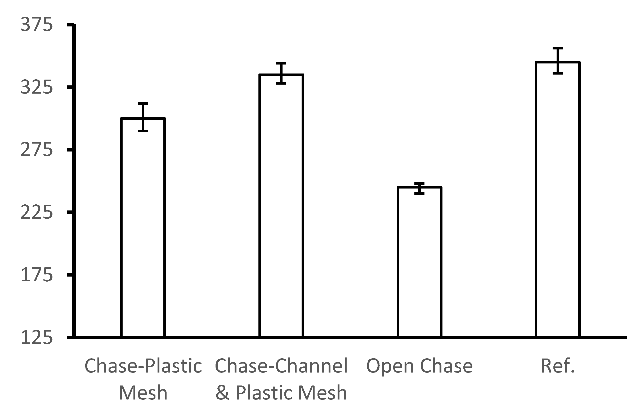
  • Lower load bearing capacity was achieved when chases are introduced in a newly built masonry walls in different directions. Approximately, 29% less strength was noted compared with the case of free chase walls.
  • The worst condition of the chases was observed for the case of a chase created in the horizontal direction in which the applied load acts in a perpendicular way on the zone containing the chase.
  • The reduction in the load carrying capacity was due to concentration of stresses in the chase region and the latter is due to the inclination of the load flow as a result of the chase depth.
  • Using galvanized steel channel and/or plastic wire mesh with cement mortar has a clear beneficial role in recovering the strength lost due to introduction of the chases with percentages recovery of 55% and 93%, respectively. This behaviour is attributed to the infill and adhesion characteristics of such renovation techniques.
  • The reference masonry wallette exhibited less lateral deformation due to its brittleness behaviour. In contrast, the repaired wallettes showed more deformation resulting from the ductile nature of the infill materials.
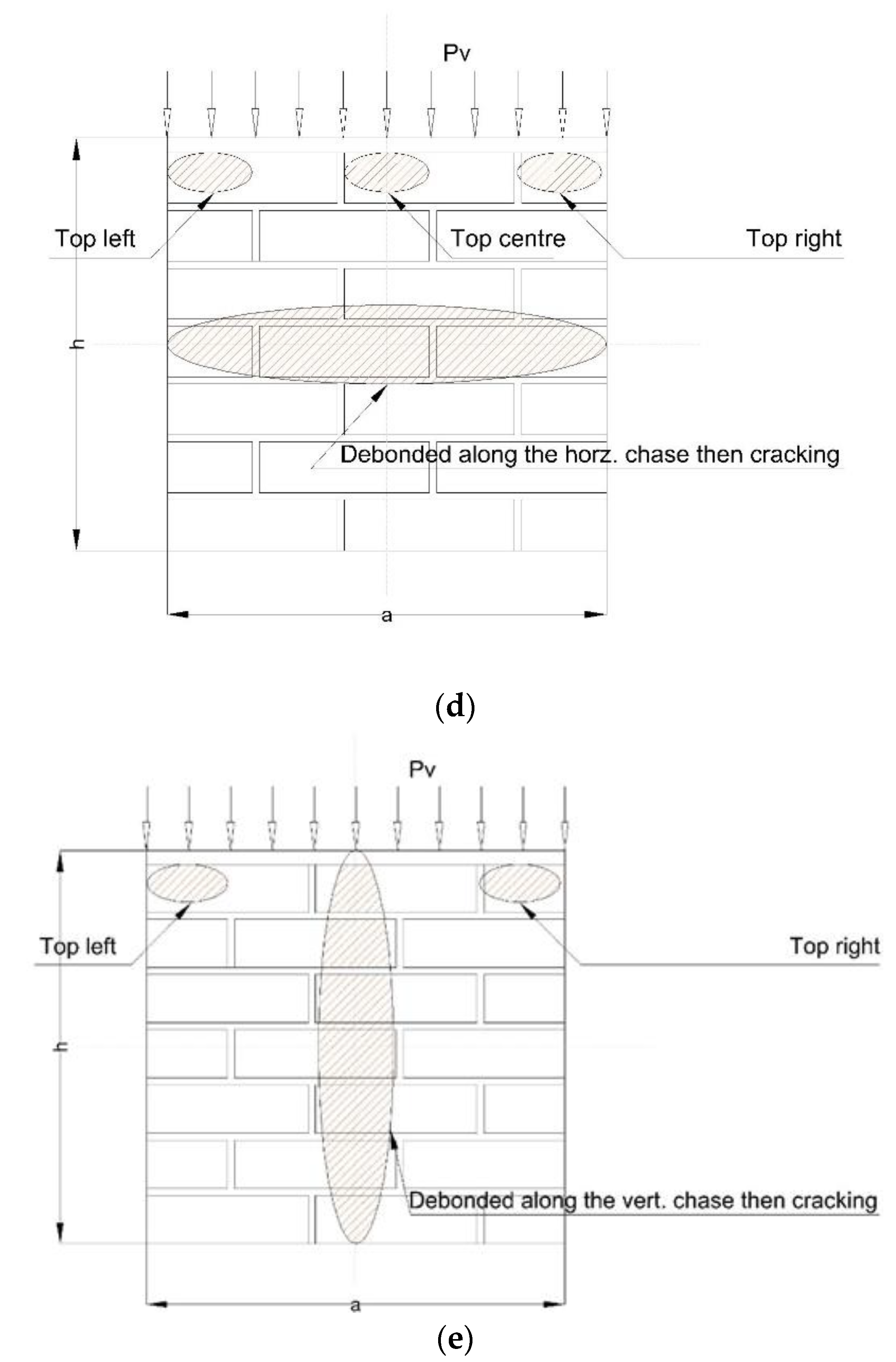
  • The dominated failure was the de-bonded of the renovation components from the interior surfaces of the chases. The beginning of the de-bonded was noted at the one third of the ultimate load carrying capacity.
  • The expressions suggested by BS EN codes for calculating the values of the compressive strength and modulus of elasticity of masonry walls need to be amended taken in consideration using a suitable factor of safety to overcome the adverse effect of the chases.

Author Contributions

A.A.-S. performed all the tests and established the correlation between all tests results. R.E. supervised the research and follow up on the methodology of the research. A.A.-S. wrote the manuscript and complemented the analysis of the results. A.A.-S. and R.E. revised the manuscript. All authors have read and agreed to the published version of the manuscript.

Funding

This research received no external funding.

Institutional Review Board Statement

Not applicable.

Informed Consent Statement

Not applicable.

Data Availability Statement

Not applicable.

Acknowledgments

The author would like to thank the technical assistance provided by the staff of Structural Lab. of Civil Engineering Department, College of Engineering, The University of Al-Qadisiyah. The efforts of Ali Abdualusain Ebady and Murtudh Mahmood are greatly appreciated.

Conflicts of Interest

The authors declare no conflict of interest is found in this paper.

References

  1. Al-Sibahy, A.; Edwards, R. Characterization of the clay masonry units and construction technique at the ancient city of Nippur. Eng. Struct. 2017, 147, 517–529. [Google Scholar] [CrossRef] [Green Version]
  2. Al-Sibahy, A.; Edwards, R. Structural evaluation for the historic Palace of King Ghazi and mechanism of its rehabilitation. Case Stud. Constr. Mater. 2020, 13, e00371. [Google Scholar]
  3. Al-Sibahy, A.; Edwards, R. Behaviour of masonry wallettes made from a new concrete formulation under compression loads at ambient temperatures: Testing and modelling. Constr. Build. Mater. 2014, 63, 271–280. [Google Scholar] [CrossRef]
  4. Fischer, K. The effects of chasing on the compressive strength of brickwork. In Proceedings of the 3rd International Brick Masonry Conference, Essen, Germany, 8–11 January 1973; pp. 106–114. [Google Scholar]
  5. Kirtschig, K.; Metje, W.R. Influence of chases and recesses on the strength of masonry. Proc. Br. Mason. Soc. 1988, 2, 61–63. [Google Scholar]
  6. SIA 266:2003. Structural Masonry; Swiss Society of Engineers and Architects: Zurich, Switzerland, 2003. [Google Scholar]
  7. ACI 530-08/ASCE 5-08/TMS 402-08. Building Code Requirements and Specifications for Masonry Structures; Masonry Standards Joint Committee (MSJC), Boulder/Farmington Hills: Reston, WV, USA, 2008. [Google Scholar]
  8. AS3700:2001. Masonry Structures; Standards Australia: Sydney, Australia, 2001. [Google Scholar]
  9. Sahlin, S. Fischer’s tests on chasing revisited the effects of chasing on the compressive strength of brickwork (3. IBMAC, Essen 1973). Mason. Int. 2007, 20, 85–90. [Google Scholar]
  10. EN 1996-1-1:2005. Design of Masonry Structures—Part 1: General Rules for Reinforced and Unreinforced Masonry; European Committee for Standardization: Brussels, Belgium, 2005. [Google Scholar]
  11. Mojsilovic, N. Masonry elements with chases: Behaviour under compression. Construct. Build. Mater. 2011, 25, 4415–4425. [Google Scholar] [CrossRef]
  12. Milani, A.S.; Lübeck, A.; Mohamad, G.; Neto, A.B.d.S.; Budny, J. Experimental investigation of small-scale clay blocks masonry walls with chases under compression. Construct. Build. Mater. 2021, 273, 121539. [Google Scholar] [CrossRef]
  13. I.Q.S No. 25. Clay Building Bricks; The Central Organization for Standardization and Quality Control: Baghdad, Iraq, 1988; Available online: https://www.google.com.hk/search?newwindow=1&source=univ&tbm=isch&q=I.Q.S+No.+25.+Clay+Building+Bricks;+The+Iraqi+Standards++:+1988.&fir=efAW8aZx17ofyM%252CoNEQCZqo8gnZeM%252C_%253BTZ7feq-XiWG1EM%252CQFPN060DwzniuM%252C_%253B2Itf7VvnFr_LPM%252C3PM3pedmUsdf9M%252C_%253B0UkI4QH3BXrcJM%252CoNEQCZqo8gnZeM%252C_%253B60yL6sNFs48RbM%252C2GzR70mWFedU8M%252C_%253B55g_8YrHaYM6LM%252C9Y6WtkACGpM4qM%252C_%253BzqNvoeC9rtPubM%252CoNEQCZqo8gnZeM%252C_%253BdXMjZ6ecE_vjcM%252C67UXnZk0ry3LMM%252C_%253BfAbQvBVqQpb6RM%252CoNEQCZqo8gnZeM%252C_%253BjZlKI9I5VuNCYM%252C9Y6WtkACGpM4qM%252C_&usg=AI4_-kRaGxhgXxAcqyM7yUDxoxcfQ58D8g&sa=X&ved=2ahUKEwjKpM_Y1Yf0AhWOfXAKHd_VCWUQjJkEegQIHxAC&biw=2144&bih=1004&dpr=0.9 (accessed on 2 November 2021).
  14. EN BS 197-1. Cement, Part 1: Compositions, Specification and Conformity Criteria for Common Cements; British Standards: 2000. Available online: http://www.puntofocal.gov.ar/notific_otros_miembros/mwi40_t.pdf (accessed on 2 November 2021).
  15. BS 882 1992. Aggregates for Concrete, Specification for Aggregates from Natural Sources for Concrete. Available online: https://shop.bsigroup.com/products/specification-for-aggregates-from-natural-sources-for-concrete-1 (accessed on 2 November 2021).
  16. BS 5628-1. Code of Practice for the Use of Masonry: Part 1: Structural Use of Unreinforced Masonry; British Standards: 2005. Available online: https://shop.bsigroup.com/products/code-of-practice-for-the-use-of-masonry-structural-use-of-unreinforced-masonry (accessed on 2 November 2021).
  17. BS EN 1052-1. Methods of Test for Masonry: Part 1: Determination of Compressive Strength; British Standards: 1999. Available online: https://www.thenbs.com/PublicationIndex/documents/details?Pub=BSI&DocID=247929 (accessed on 2 November 2021).
  18. Oliveira, D.V. Experimental and Numerical Analysis of Blocky Masonry Structures under Cyclic Loading. Ph.D. Thesis, The University of Minho, Braga, Portugal, 2003. [Google Scholar]
  19. Drysdale, R.G.; Hamid, A.A. Masonry structures behavior and design. In The Masonry Society, 3rd ed.; The Masonry Society: Longmont, CO, USA, 2008. [Google Scholar]
  20. BS ISO 1920-10. Testing of Concrete, Part 10: Determination of Static Modulus of Elasticity; British Standards: 2009. Available online: https://civilnode.com/download-standard/10661023633076/iso-1920-10-testing-of-concrete-part-10-determination-of-static-modulus-of-elasticity-in-compression (accessed on 2 November 2021).
  21. BS EN 772-1. Methods of Test for Masonry Units: Part 1: Determination of Compressive Strength; British Standards: 2000. Available online: https://standards.iteh.ai/catalog/standards/cen/1fa1b3c1-83ab-4a43-b744-bea787fe5b2c/en-772-1-2000 (accessed on 2 November 2021).
Figure 1. Plastic wire mesh and galvanized steel channel used in the renovation of the chases.
Infrastructures 06 00160 g001
Figure 2. Construction of the masonry wallettes.
Infrastructures 06 00160 g002
Figure 3. Finalizing the top surface of the wallettes and using underneath steel plate for lifting.
Infrastructures 06 00160 g003
Figure 4. Creation of the vertical and horizontal chases.
Infrastructures 06 00160 g004
Figure 5. Renovation of the chases and cement rendering of the wallettes: (a) insertion of the service pipes; (b) fixing the galvanized steel channel; (c) galvanized steel channel with plastic wire mesh and mortar; (d) plastic wire mesh and mortar; and (e) rendering the wallettes with cement mortar.
Infrastructures 06 00160 g005aInfrastructures 06 00160 g005b
Figure 6. Set up of the test and locations of the measured deformations.
Infrastructures 06 00160 g006
Figure 7. Load−vertical deformation for the masonry wallettes containing horizontal chases and masonry wallette without chase.
Infrastructures 06 00160 g007
Figure 8. Load−lateral deformation for the masonry wallettes containing horizontal chases and masonry wallette without chase.
Infrastructures 06 00160 g008
Figure 9. Load−vertical deformation for the masonry wallettes containing vertical chases and masonry wallette without chase.
Infrastructures 06 00160 g009
Figure 10. Load−lateral deformation for the masonry wallettes containing vertical chases and masonry wallette without chase.
Infrastructures 06 00160 g010
Figure 11. Statistical variation of the ultimate load for the wallette samples containing horizontal chases and masonry wallette without chase.
Infrastructures 06 00160 g011
Figure 12. Main critical regions of the wallettes’ failure modes under axial compression load: (a) intact wallette sample; (b) wallettes with horizontal chases; (c) wallettes with vertical chases; (d) wallettes with horizontal chases containing infill materials; (e) wallettes with vertical chases containing infill materials.
Infrastructures 06 00160 g012aInfrastructures 06 00160 g012b
Table 1. Properties of the solid brick units.
Compression Test ResultsAbsorption Test ResultsLimitations of Iraqi Standards No. 25-1998 [13]
No. of SampleIndividual ReadingAverage Individual ReadingAverage Lower Limits of Compression
18.439.7123.8223.98TypeIndividualAverage
28.6925.20A1618
38.6622.34B1113
413.3125.76C79
610.1717.36Upper limits of absorption
79.6523.50TypeIndividualAverage
810.8624.25A2220
97.7729.67B2624
108.6923.60C2826
Table 2. Summary of the results.
No.Type of SpecimenFmax (kN)Aw (m2) f k
(MPa)
E (MPa)Max. Ver.Disp (mm)Max. Lat.Disp.
(mm)
%
1Reference 3450.1442.39958.50.8-
2Horizontal-Chase open2450.1441.70949.11.8−29
3Horizontal-Chase with plastic mesh3000.1442.081517.23.3−13
4Horizontal-Chase-channel and plastic mesh3350.1442.321585.31.5−2.8
5Vertical-Chase open2950.1442.041217.31.6−14
6Vertical-Chase with plastic mesh3010.1442.097745.75.4−12.5
7Vertical-Chase-channel and plastic mesh3390.1442.351675.21.5−1.7
Table 3. The proposed factors of safety (F.S) for the compressive strength aspect of different masonry wallettes.
No.Type of SpecimenThe Measured Value of f k The Theoretical Value of f k F. S
1Reference 2.393.50.68
2Horizontal-Chase open1.703.50.49
3Horizontal-Chase with plastic mesh2.083.50.59
4Horizontal-Chase-channel and plastic mesh2.323.50.66
5Vertical-Chase open2.043.50.58
6Vertical-Chase with plastic mesh2.093.50.60
7Vertical-Chase-channel and plastic mesh2.353.50.67
Publisher’s Note: MDPI stays neutral with regard to jurisdictional claims in published maps and institutional affiliations.

