Abstract
The latest advancements in road asphalt materials and construction technologies have increased the difficulty for engineers to select the appropriate pavement design solution with consideration of proper timing for maintenance planning. On the other hand, Building Information Modeling (BIM) tools allow practitioners to efficiently store and manage large amounts of data, supporting decision making in road asphalt pavement design and management. The present work focused on the elaboration of a BIM-based maintenance analysis tool for the specific evaluation of several condition indicators and the selection of proper maintenance solutions designed to include alternative materials and advanced recycling technologies. A traditional BIM workflow was integrated with additional user-defined property sets to investigate the need for maintenance at the present date and predict the degradation curve of the condition indicators through the least square interpolation of time series of data. The analysis tool also provided the selection of available pavement alternatives from a library of designed solutions based on their compliance with project-specific constraints (maximum budget, minimum useful life, and availability of secondary raw materials and in-place recycling technologies). The proposed BIM tool aims to be a practical and dynamic way to integrate maintenance planning considerations into road pavement design, encouraging the use of digital tools in the road industry and ultimately supporting a pavement maintenance decision-making process oriented towards a circular economy.
1. Introduction
It is now known that the road transport system plays a fundamental and strategic role in the economic and social development of a country [1]. For the purposes of more correct road management, ordinary and extraordinary maintenance interventions are carried out to ensure that the pavement maintains specific functional and structural characteristics throughout its service life [2].
The implementation of a pavement management system requires the definition of appropriate maintenance criteria and condition indicators, monitoring of the state of the road pavement, and archiving and processing of data, in order to plan and schedule maintenance interventions [3,4].
Several studies have been carried out to analyze the benefits of setting up proper maintenance planning; for example, the study carried out by Tavakoli et al. [5] shows that without using an effective maintenance program, a city may see the cost of maintaining their transportation system increase in the future to four or five times what it would cost if the proper maintenance were done before.
The scheduling of maintenance interventions, however, hides problems that are not easy to solve, linked to the high number of roads to manage, the wide range of possible pavement distresses and relative causes of deterioration, and the limited economic resources for maintenance interventions.
Picado-Santos at al [6] developed a maintenance algorithm based on a single condition indicator and several imposed constraints on costs, number of interventions, intervention priorities and more; they estimated the costs involved in the development of the overall system and having the system up and running, including the hardware needed, equal to less than one cent per square meter of the total road network—which is about 150 times less than the cost of a simple surface treatment. It is clearly profitable to have an effective tool to aid decisions about financial resource allocation to maintenance actions in any road network.
Furthermore, the preventive preparation of a maintenance plan makes it possible to reuse waste, such as milled asphalt material, in order to provide ecosustainable solutions and lower the total costs of road network maintenance [7,8].
As stated by Koch et al. [9], the process of pavement condition assessment is divided into three parts: data collection, distress identification and classification, and distress assessment. Some researchers focused on the implementation of automated and efficient monitoring techniques.
For example, Jang et al. [10] installed into a car a triaxial accelerometer, GPS sensor, microcomputer and local memory for monitoring data collection; this allowed the continuous gathering of detailed surveys on the status of the network in a short time at low cost.
Kamaliardakani et al. [11] automated the survey of cracks on the pavement surface by implementing an algorithm for the identification of cracks that have exceeded a certain threshold using 2D images obtained through photographic surveys.
The issue of computational time has been analyzed by Jiang and Tsai [12], who proposed a monitoring system based on a high-resolution 3D laser imaging system. In 3D pavements however, with high data resolution, the computation time of a dynamic optimization algorithm increased exponentially, showing a limited possibility of implementation and low performance in real applications.
Instead, to date, pavement condition assessment and relative decision making is predominantly performed manually.
In recent years, BIM tools began to spread across practitioners to efficiently store and manage large amounts of data, supporting decision making in road asphalt pavement design and management [13,14].
Delgado et al. [15] analyzed the possibility of inserting monitoring data into a BIM model, obtaining the advantage of evaluating changes already in the design phase. Potential modifications can be easily implemented; for example, if future upgrades, repairs, alterations to the original structure, or changes in monitoring methods are undertaken, the BIM model along with the sensor data can be readily updated.
Looking more specifically at the use of BIM to manage pavement structural data, Tang et al. [16] developed a digital model of a road pavement, aimed at performing structural controls and checking the accumulated rutting damage at the end of the service life based on the physical and mechanical properties of the asphalt mixtures, imported through a customized script.
Despite the increasing interest in the possibilities offered by the integration of road pavement maintenance management tools in the BIM environment, the following have been identified as the main topics on which future research should focus:
- the identification of specific sets of parameters, beyond the simple element/material identifier, that enable the integration of more accurate and complete analysis;
- the elaboration of flexible maintenance tools to let the user apply changes and update project-specific constraints;
- the automatization of maintenance planning calculations and bidirectional exchange of information between the BIM platform and the analysis tool.
In the present study, a support system for the optimum management of all this information is elaborated, which is associated with both the mechanical characteristics that make up the layers of the pavement and the global condition of the pavement, with specific focus on the management of maintenance interventions by reusing secondary resources in the asphalt mixtures for road pavements.
The collection and storing of pavement data and the pavement management system can be supported by BIM tools in such a way that all the information, appropriately protected, is shared and dynamically updated with time.
The proposed methodology mainly consists of three phases:
- acquisition of information related to the road geometry and the mechanical characteristics of the materials making up the layers of the asphalt pavement;
- modeling of the road pavement in a BIM environment;
- implementation of a decision support system for the management of maintenance processes.
The decision support system has been elaborated using Dynamo, an Autodesk BIM tool that allows non-expert users to script pieces of code that dynamically interact with certain features of a BIM model. The code has been divided into two different blocks, through which the following results were pursued:
- assessment of the road condition in terms of evaluation of the degradation curve of selected condition indicators and timing of the required maintenance interventions;
- evaluation of the compatibility of a library of designed pavement solutions involving secondary raw materials and cold recycling technologies with external imposed constraints.
2. Data Collection
The survey campaign took place in the Municipality of Fondi in Italy where, in the first analysis, the paper-based documentation needed to carry out this work was collected.
Three urban roads present in the municipal area have been considered. For each, the following information was obtained:
- Geometric configuration of road sections (length and width of the roadway). All the surveyed roads had a 7 m wide carriageway. The first road section was 460 m long, the second one 500 m long and the third one 800 m long;
- Traffic data: the first road section had an average daily traffic (ADT) of 20,099 vehicles with 7% heavy vehicles, the second one an ADT equal to 5000 vehicles and 3% heavy vehicles, and the third an ADT of 15,000 vehicles with 6% heavy vehicles;
- Pavement configuration in terms of thicknesses of the asphalt layers on site, which were read from the available documentation of the pavement construction works;
- Characteristics of the subgrade, which was classified as A2-5 soil according to EN 13242;
- Mechanical and volumetric characteristics of the asphalt mixtures, which were known from the special tender requirements of the road works.
3. Road Condition Indicators
In the present work, the road condition was stated using two state indicators, of which two global indicators were based on multiple distresses surveyed on the asphalt pavement, and two specific distresses indicators were based on the empirical prediction of the accumulation of fatigue cracking and rutting distresses.
The recognition of the distresses of a flexible road pavement can be carried out on the basis of the SHRP “Distress Identification Manual” catalogue [17]. The types of structural distresses most frequently encountered on the roads under study are:
- fatigue cracking;
- thermal cracking;
- longitudinal and transverse cracking;
- rutting;
- distressed patches;
- potholes.
One of the many indicators suggested by the literature to provide synthetic and global information on the deterioration state of the pavement is the Present Serviceability Index (PSI). The PSI is a synthetic indicator that can be assessed visually based on the sample unit or can be evaluated analytically after the onsite survey of the road distresses, using Equation (1):
where:
- SV is the mean slope variance in the two-wheel paths (rad2);
- RD is the rut depth (in);
- C and P are the total areas covered in cracks and deteriorated patches per 1000 ft2 of pavement area (ft2/1000 ft2).
The PSI is included in the range [0; 5], where 5 corresponds to excellent condition of the pavement surface, while 0 indicates that the pavement is completely deteriorated.
Another common global state indicator used in flexible pavements is the Present Condition Index (PCI). In the present work, the PCI of each pavement section was analytically calculated using the simplified formula (see Equation (2)) adopted by China’s Ministry of Transportation [18]. The simplified formula allows for the automation of PCI calculations, as previously done by other authors for the elaboration of pavement-related decision-making tools [19,20].
where:
- Wi is the is the weight assigned to the i-th class of pavement distress [18];
- Ai is the area or the linear extension of the i-th class of pavement distress (m2 or m);
- A is the area or length of the surveyed road section (m2 or m).
The PCI is included in the range [0; 100], where 100 corresponds to excellent condition of the road surface, while 0 corresponds to a completely deteriorated road surface.
The accumulation of fatigue cracking and rutting distresses on the asphalt pavement was also checked using empirical damage accumulation laws based on the stress-strain state of the pavement modelled as a linear elastic, isotropic and homogeneous multilayer. The cumulative fatigue damage (CD), which should always be lower than 1, was calculated through Miner’s law, reported in Equation (3):
where:
- ni is the number of passages of the equivalent standard axle load (ESAL) in the i-th period of analysis (season), which is computed supposing that the ESALs occurring over the service life, determined with the AASTHO Design method [21], are evenly distributed between the four seasons.
- Ni is the number of passages of the ESAL in the i-th period of analysis (season) that leads to an extension of fatigue cracking damage up to 10% of the lane area of the road pavement during its useful life and is determined according to the Asphalt Institute fatigue prediction law [22].
The rut depth (RD), which should never be deeper than 2 cm, is predicted through the Vaerstaten law, as shown in Equation (4):
where:
- εp,ij∙is the permanent deformation in the i-th season that is accumulated in the j-th asphalt layer of the pavement after the mentioned ESAL passages, determined according to the Kaloush and Witczak model [23], based on the vertical compressive strain obtained from the linear elastic multilayer model;
- hj is the thickness of the j-th asphalt layer. It should provide a concise and precise description of the experimental results, their interpretation, as well as the experimental conclusions that can be drawn.
4. Library of Asphalt Solutions
The rational design of asphalt pavements was carried out to create a library of pavement solutions to be adopted when a maintenance intervention is needed to restore the structural functionality of the road pavement and improve its resistance towards the accumulation of distresses. The maintenance interventions entailed the demolition of the distress road asphalt layers (i.e., wearing course, binder and base layers) and their reconstruction with traditional and eco-sustainable asphalt mixtures designed in the laboratory to respond to the mechanical and volumetric requirements of the Special Tender Specifications of road works.
In particular, the available mix design involved:
- a traditional asphalt mixture for the wearing course involving a blend of limestone and basaltic aggregates with 5.5% bitumen by the weight of aggregates;
- three alternative asphalt mixtures for the binder layer; the first is a traditional asphalt mixture with virgin limestone aggregates and 5% bitumen by the weight of aggregates, the second involves 4% jet grouting waste (waste material deriving from land consolidation of civil engineering works) in substitution of limestone filler and 5.2% bitumen, and the third has 4% fly ash (waste from the combustion process of coal for the production of electricity) in substitution of limestone filler with 4.8% bitumen.
- two alternative asphalt mixtures for the base layer, of which the first is a traditional mixture with limestone aggregates and 4% bitumen by the weight of aggregates, while the second is a cold-recycled asphalt that entails the reuse of the milled asphalt derived from the wearing course and binder layer directly in situ.
All the mentioned asphalt mixtures have been mechanically investigated in terms of Indirect Tensile Stiffness Modulus according to Annex C of EN 12697-26. More details can be found in Oreto et al. [24].
Therefore, several solutions have been designed with different combinations of the mentioned materials and layer thicknesses to ensure at least 15 years of service life under the predicted ESAL passages.
Each solution was also characterized by the unit cost for the supply and laying of the asphalt mixtures of each layer; unit costs were obtained as the average costs gathered from a few local contractors that produce traditional and recycled asphalt mixtures for road pavements
5. Maintenance Criteria and Constraints
In general, for the parts of the infrastructure that suffer degradation in relation to use, the values assumed by each status indicator undergo a variation (decrease) over time. Three main maintenance activities can then be identified:
- ordinary or preventive maintenance, which entails sealing the low-severity cracks that appear on the pavement surface. These activities have the purpose of extending the useful life of the pavement and delay structural failure with low-cost and non-structural interventions;
- pavement rehabilitation, which usually involves the demolition and reconstruction of the wearing course and/or binder layer. This maintenance intervention is usually carried out when a localized area of the pavement surface shows low to medium-severity distresses that require structural intervention to restore the original road conditions;
- pavement reconstruction, when the deterioration level of the pavement is so high that it cannot be recovered with localized surface interventions.
In the following paper, reconstruction intervention was triggered by the achievement of at least one of the following limit conditions:
- CD ≥ 1;
- RD ≥ 2 cm;
- PSI ≤ 2;
- PCI < 50.
In detail, Figure 1 shows the triggering conditions for pavement reconstruction intervention. In particular, a distinction was made between a mandatory maintenance intervention, when at least one of the global indicators was under the acceptability threshold, and a required maintenance intervention, when CD or RD exceed the limit threshold—indicating a structural failure, but still an overall good condition of the pavement surface.
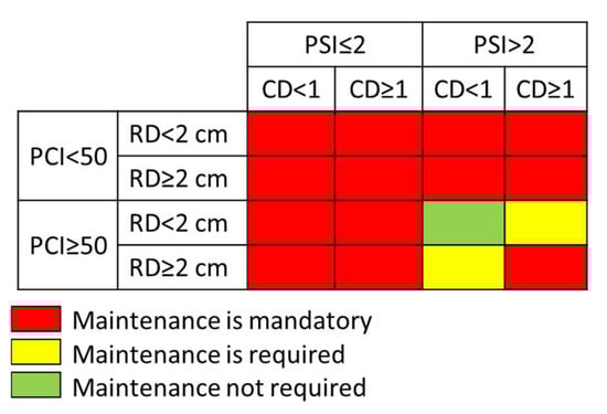
Figure 1.
Triggering condition for reconstruction intervention based on the values of cumulative fatigue damage (CD), rut depth (RD), Pavement Condition Index (PCI) and Pavement Serviceability Index (PSI).
Once defined whether or not an intervention on the road section is necessary, the next step involves the selection of one or more possible pavement solutions that are compliant with the following project constraints:
- economic constraint, namely the budget assigned to each section;
- minimum useful life during which the infrastructure must meet specific functional and structural requirements;
- availability of secondary raw materials (such as the jet grouting waste and fly ash) and cold in-place recycling technology to lay ecosustainable asphalt mixtures.
The logical process for the screening of the library of pavement solutions based on the mentioned constraints is reported in Figure 2.
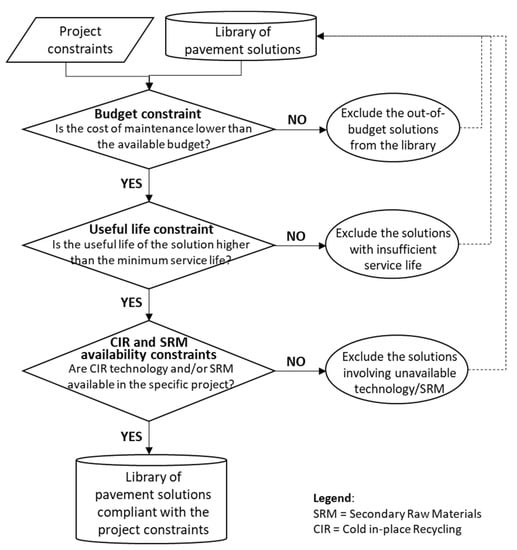
Figure 2.
Flow diagram that shows the screening process of the library of asphalt pavement solutions based on the project constraints.
6. Building Information Modeling
The creation of the BIM of the road structure, performed though Autodesk software, started from identifying the study area in the InfraWorks calculation code, exporting the IMX format to Civil3D and obtaining the topographic surface and the track of the three urban roads to be modelled (see Figure 3a).
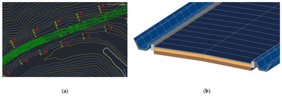
Figure 3.
Modeling of (a) road alignment and (b) pavement parametric section.
Then, we created the parametric road sections (see Figure 3b) and extruded them alongside the alignment. The three-dimensional solids were later imported in Revit calculation code as a CAD link, thus allowing an immediate exchange and update of information with Dynamo, a Python-based programming environment aimed at improving the efficiency of BIM processes and creating custom analytical tools that exchange information with the model. In Dynamo, the single lines of code are represented by the nodes, while the links allow the transfer of information between the nodes.
On this way, an accurate model containing the elements of the pavement solid geometry was created to be further integrated with user-defined property sets, which introduce several customized, controllable and dynamically editable parameters needed to manage the maintenance process.
In particular, the “Pavement Condition” property set included the extension and severity of all the pavement distresses surveyed on the road pavement used to calculate the PSI and the PCI, other than the values of CD and RD, at the time of the analysis.
Additionally, the property set “Maintenance solutions” was arranged to be assigned the results obtained from the screening of the library of pavement solutions after the execution of the analysis tool.
Lastly, the property set “Project constraints” was created to properly store the value of the maximum budget, minimum required service life and availability of alternative materials and construction technologies.
7. Discussions
The pavement BIM, conveniently supported by the developed BIM-based analysis tool, gives the possibility of collecting the monitoring data obtained from the on-site surveys of the pavement condition, setting up the proper timing for maintenance interventions and providing a list of pavement solutions, eventually involving the reuse of waste and secondary raw materials—complying with the project-specific constraints.
Looking at the implementation of the designed management tool and its relative implications, to establish an automated link between the disaggregated database (expressed by a MS Excel spreadsheet) and the BIM model (Autodesk Civil3D), a custom script was developed using visual scripting software (Autodesk Dynamo), which extracts the information from the BIM model (such as areas, volumes, materials, and values of the custom property sets) and applies changes based on conditions set through code scripts.
Figure 4 shows the flow diagram of the developed BIM-based maintenance tool and the path followed by the data collected from paper-based documentation to integration and analysis in the BIM environment.
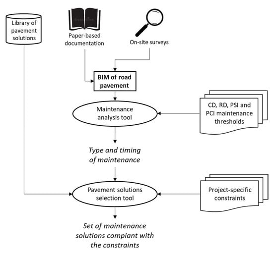
Figure 4.
Flow diagram representing the exchange of information, the inputs and the main steps included in the BIM-based maintenance tool.
As a first step, the information collected from on-site surveys were organized into an Excel spreadsheet according to a specific template, imported in the Dynamo environment, and assigned to predefined property sets associated with the 3D solids using the “Data.ImportExcel” and “GetPropertySetValues” nodes.
Then, the maintenance analysis tool was developed aiming at finding the proper timing for an intervention at the time of the analysis. In the first place, the PSI and PCI indicators were calculated based on the extension and severity of the surveyed distresses according, respectively, to Equations (1) and (2). Then, it was verified whether the CD and RD were below the threshold values. If yes, an intervention must take place; otherwise, you will go on to evaluate the PSI. The output of the first step of the decision-making process was the necessity of carrying out a maintenance intervention at the time of the analysis. In case maintenance is needed, the program automatically reports the current date to which the intervention refers.
Whenever maintenance intervention is not needed at the time of the analysis, the algorithm searches for the time series of each indicator that have been evaluated in past analyses to reconstruct the future evolution of the indicators themselves.
These degradation curves, expressed analytically through the interpolation of the time series, represent the variation of a status indicator as a function of time and return the future date at which maintenance intervention will be necessary.
In the present work, each degradation curve was obtained through the least squares regression as linear, exponential or polynomial law; for each indicator, the selected degradation curve was the one with the maximum coefficient of determination.
It is therefore possible, for a given limit threshold, to obtain the year of intervention though the node “DataTime.ByDate”.
Considering the four indicators, the future date of the maintenance intervention is obtained as the minimum between the four time intervals, when the first indicator lowers below the limit threshold (see from Figure 5a–d).
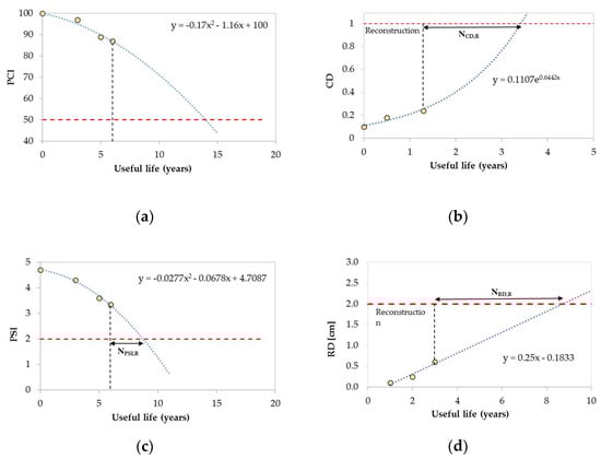
Figure 5.
Qualitative representation of the interpolation of historic series of condition indicators versus time to predict the timing of the next maintenance intervention for (a) pavement condition index, (b) cumulative fatigue damage, (c) present serviceability index and (d) rut depth.
The pavement condition can also be displayed graphically at a specific date through nodes that allow you to change the color of the element according to the value of certain parameters (see Figure 6a). For example, the graphic display of the output of the maintenance analysis tool has been shown for the three urban roads under analysis (Figure 6b), where the road where it is necessary to intervene is highlighted in red, while green represents good conditions of the pavement. Instead, the yellow color represents a road section characterized by severe fatigue cracking but global condition indicators still above the intervention thresholds.
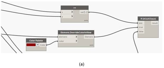
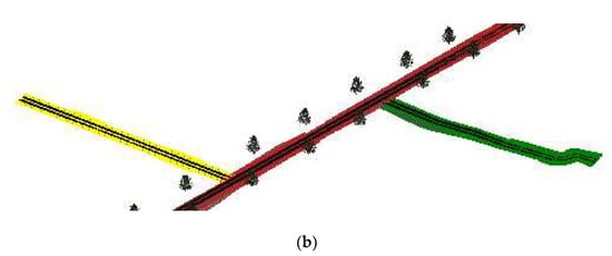
Figure 6.
Visualization of the results: (a) visual script for adding a color scheme to the model based on the value of the status indicators and (b) graphical result as seen in the modeling environment.
Once verified, the present or future date of the maintenance intervention on the analyzed road section, the screening of the library of asphalt solutions and the selection of the those compliant with the project constraints was carried out.
In order to identify the combination that best meets the requirements imposed by the managing bodies, project constraints were considered, such as: the minimum useful life required for the work, the usable budget, the availability or not of alternative secondary raw materials and cold in-place recycling technology. As an example, Figure 7a shows the pieces of code that verify the compliance of the set of proposed pavement solutions with the budget constraint.
Figure 7.
Visual scripts to select the available pavement solutions from the library: (a) example of verification of the budget constraint and (b) example of final library of solutions indicating the main features or the reason for exclusion.
Where possible, the algorithm will result in a solution, obtained downstream of the filtering operations; otherwise, it will be discarded (see Figure 7b).
Therefore, once the BIM of the pavement is set up, the elaborated analysis tool can be launched to obtain three main outputs: the proper timing for the next maintenance intervention, the priority of each pavement section and the list of available maintenance solutions selected from a predetermined library.
To date, few researchers have explored the potentiality of current BIM tools to enhance the definition of pavement maintenance strategies with a similar approach to the present work. For example, Bosurgi et al. [25] elaborated specific attributes related to pavement conditions to extend the informative content of the BIM objects and set up a proper maintenance analysis tool, similar to what has been done in the present work.
Instead, Wang [13] elaborated a BIM tool to set up the priority of intervention through the analytic hierarchy process, based only on in-situ distress survey data—differently to what has been done in the present work, in which the need for maintenance has been defined based on multiple indicators, including distress data and predictive damage accumulation laws.
Similar constraints for the selection of optimal maintenance solutions were introduced into a BIM tool by Cao et al. [19], who elaborated an algorithm for the selection of proper recycling technology depending on the type of distress and the availability of each treatment. In the present work, the project constraints were extended to the budget availability and the minimum service life of the maintenance solutions.
Therefore, the present tool sets a preliminary base to improve the efficiency of the road managing bodies in setting up proper timing for maintenance and providing sustainable asphalt solutions.
Comparing the BIM-based management framework with current pavement management practices, some major improvements should be pointed out:
- the timing of maintenance is defined rationally through predictive equations and interpolation of distress survey data, while current practice mostly relies on predetermined time intervals that often fail to ensure a good quality of the pavement surface continuously over time;
- alternative asphalt solutions are proposed together with traditional ones to promote circularity and cost savings and let managing authorities visualize the actual advantages of more sustainable solutions involving waste and cold recycling technologies, as opposed to the current practice of following the production–construction–disposal path.
8. Conclusions
The present study aimed at the elaboration of a BIM-based methodology related to the management of pavement data and the elaboration of pavement maintenance plans involving a library of designed asphalt pavement solutions. The main objective was to create a methodological structure implemented in a BIM environment for the automated analysis of the deterioration state of a road pavement through specific condition indicators, namely the Present Serviceability Index, the Pavement Condition Index, the cumulated fatigue cracking damage, and the rut depth. The implemented methodology also allowed a graphic display of the actual functional state of the pavement to be obtained and the identification of any possible maintenance interventions, as well as the associated pavement configuration, selected from a library of design solutions.
However, for future developments, an improvement of the model is expected through the expansion of the database of design solutions, with greater attention to the reuse of secondary raw materials, through the integration of the algorithm with structural methods of design/verification of the pavement structures and through the implementation of further decision support systems, including environmental and economic analysis of the pavement’s life cycle.
Author Contributions
Conceptualization, S.A.B. and F.R.; methodology, C.O., R.V. and F.R.; software, C.O., S.A.B. and L.M.; validation, R.V. and N.V.; data curation, L.M. and C.O.; writing—original draft preparation, C.O.; writing—review and editing, S.A.B.; visualization, C.O., R.V. and N.V.; supervision, S.A.B. and F.R.; funding acquisition, S.A.B. All authors have read and agreed to the published version of the manuscript.
Funding
This research was developed within the Projects of National Interest—PRIN 2017 “Stone pavements. History, conservation, valorisation and design” (20174JW7ZL) financed by the Ministry of Education, University and Research (MIUR) of the Italian Government.
Institutional Review Board Statement
Not applicable.
Informed Consent Statement
Not applicable.
Data Availability Statement
The data used to support the findings of this study are available from the corresponding author upon request.
Conflicts of Interest
The authors declare no conflict of interest.
References
- Ivanova, E.; Masarova, J. Importance of road infrastructure in the economic development and competitiveness. Econ. Manag. 2013, 18, 263–274. [Google Scholar] [CrossRef]
- Macorig, D.; Ristori, C.; Bertoli, V. Development of a method to evaluate the priorities of intervention on the road network of the Province of Pisa. Transp. Res. Procedia 2020, 45, 103–110. [Google Scholar] [CrossRef]
- Hosseini, S.A.; Smadi, O. How prediction accuracy can affect the decision-making process in pavement management system. Infrastructures 2021, 6, 28. [Google Scholar] [CrossRef]
- Sayadinia, S.; Beheshtinia, M.A. Proposing a new hybrid multi-criteria decision-making approach for road maintenance prioritization. Int. J. Qual. Reliab. Manag. 2020, 38, 1661–1679. [Google Scholar] [CrossRef]
- Tavakoli, A.; Lapin, M.S.; Figueroa, J.L. PMSC: Pavement management system for small communities. J. Transp. Eng. 1992, 118, 270–280. [Google Scholar] [CrossRef]
- Picado-Santos, L.; Ferreira, A.; Antunes, A.; Carvalheira, C.; Santos, B.; Bicho, M.; Quadrado, I.; Silvestre, S. Pavement management system for Lisbon. ICE Proc. Munic. Eng. 2004, 157, 157–165. [Google Scholar] [CrossRef]
- Veropalumbo, R.; Russo, F.; Oreto, C.; Biancardo, S.A.; Zhang, W.; Viscione, N. Verifying laboratory measurement of the performance of hot asphalt mastics containing plastic waste. Measurement 2021, 180, 109587. [Google Scholar] [CrossRef]
- Russo, F.; Veropalumbo, R.; Biancardo, S.A.; Oreto, C.; Scherillo, F.; Viscione, N. Reusing jet grouting waste as filler for road asphalt mixtures of base layers. Materials 2021, 14, 3200. [Google Scholar] [CrossRef] [PubMed]
- Koch, C.; Georgieva, K.; Kasireddy, V.; Akinci, B.; Fieguth, P. A review on computer vision based defect detection and condition assessment of concrete and asphalt civil infrastructure. Adv. Eng. Inform. 2015, 29, 196–210. [Google Scholar] [CrossRef] [Green Version]
- Jang, J.; Yang, Y.; Smyth, A.W.; Cavalcanti, D.; Kumar, R. Framework of data acquisition and integration for the detection of pavement distress via multiple vehicles. J. Comput. Civ. Eng. 2017, 31, 04016052. [Google Scholar] [CrossRef]
- Kamaliardakani, M.; Sun, L.; Ardakani, M.K. Sealed-crack detection algorithm using heuristic thresholding approach. J. Comput. Civ. Eng. 2016, 30, 04014110. [Google Scholar] [CrossRef]
- Jiang, C.; Tsai, Y.J. Enhanced crack segmentation algorithm using 3D pavement data. J. Comput. Civ. Eng. 2016, 30, 04015050. [Google Scholar] [CrossRef]
- Wang, Y. Research on pavement preventive maintenance decision-making method based on BIM technology. J. Phys. Conf. Ser. 2021, 1744, 022094. [Google Scholar] [CrossRef]
- Biancardo, S.A.; Viscione, N.; Oreto, C.; Russo, F. BIM approach for smart infrastructure design and maintenance operations. In Transportation Systems for Smart, Sustainable, Inclusive and Secure Cities; IntechOpen: London, UK, 2020; pp. 297–312. [Google Scholar]
- Delgado, J.M.D.; Butler, L.J.; Brilakis, I.; Elshafie, M.Z.E.B.; Middleton, C.R. Structural performance monitoring using a dynamic data-driven BIM environment. J. Comput. Civ. Eng. 2018, 32. [Google Scholar] [CrossRef] [Green Version]
- Tang, F.; Ma, T.; Guan, Y.; Zhang, Z. Parametric modeling and structure verification of asphalt pavement based on BIM-ABAQUS. J. Autom. Constr. 2020, 111, 103066. [Google Scholar] [CrossRef]
- Miller, J.S.; Bellinger, W.Y. Distress Identification Manual for the Long-Term Pavement Performance Program (No. FHWA-RD-03-031). Federal Highway Administration, United States. 2003. Available online: https://www.fhwa.dot.gov/publications/research/infrastructure/pavements/ltpp/13092/13092.pdf (accessed on 19 September 2021).
- MOT (Ministry of Transport of the People’s Republic of China). Highway Performance Assessment Standards; China Communications Press: Beijing, China, 2007.
- Cao, W.; Wang, A.; Yu, D.; Liu, S.; Hou, W. Establishment and implementation of an asphalt pavement recycling decision system based on the analytic hierarchy process. Resour. Conserv. Recycl. 2019, 149, 738–749. [Google Scholar] [CrossRef]
- Yu, J.; Zhang, X.; Xiong, C. A methodology for evaluating micro-surfacing treatment on asphalt pavement based on grey system models and grey rational degree theory. Constr. Build. Mater. 2017, 150, 214–226. [Google Scholar] [CrossRef]
- American Association of State Highway and Transportation Officials (AASHTO). Guide for Design of Pavement Structures; AASHTO: Washington, DC, USA, 1993. [Google Scholar]
- Asphalt Institute. Thickness Design Manual; Research Report 82-2; Asphalt Institute: Lexington, KY, USA, 1982. [Google Scholar]
- Kaloush, K.E.; Witczak, M.W. Development of a permanent to elastic strain ratio model for asphalt mixtures. In Development of the 2002 Guide for the Design of New and Rehabilitated Pavement Structures; NCHRP: Washington, DC, USA, 2000; pp. 1–37. [Google Scholar]
- Oreto, C.; Russo, F.; Veropalumbo, R.; Viscione, N.; Biancardo, S.A.; Dell’Acqua, G. Life cycle assessment of sustainable asphalt pavement solutions involving recycled aggregates and polymers. Materials 2021, 14, 3867. [Google Scholar] [CrossRef] [PubMed]
- Bosurgi, G.; Pellegrino, O.; Sollazzo, G. Pavement condition information modelling in an I-BIM environment. Int. J. Pavement Eng. 2021, 1–16. [Google Scholar] [CrossRef]
Publisher’s Note: MDPI stays neutral with regard to jurisdictional claims in published maps and institutional affiliations. |
© 2021 by the authors. Licensee MDPI, Basel, Switzerland. This article is an open access article distributed under the terms and conditions of the Creative Commons Attribution (CC BY) license (https://creativecommons.org/licenses/by/4.0/).