Article

Seismic Capacity Estimation of a Masonry Bell-Tower with Verticality Imperfection Detected by a Drone-Assisted Survey †

by
Francesco Micelli
1,
Alessio Cascardi
2,* and
Maria Antonietta Aiello
1
1
Department of Innovation Engineering, University of Salento, 73100 Lecce, Italy
2
ITC-Construction Technologies Institute, CNR-Italian National Research Council, 70124 Bari, Italy
*
Author to whom correspondence should be addressed.
Presented at REHABEND 2020 Congress, https://www.rehabend.unican.es, 28–30 September 2020.
Infrastructures 2020, 5(9), 72; https://doi.org/10.3390/infrastructures5090072
Submission received: 9 August 2020 / Revised: 24 August 2020 / Accepted: 3 September 2020 / Published: 8 September 2020
(This article belongs to the Special Issue Selected Papers from the REHABEND 2020 Congress)

Abstract

:
Masonry towers are considered an important part of cultural heritage due to their architectural and historical value. From a structural perspective these kind of buildings are considered slender elements, the same as a cantilever beam. In real cases it is not easy to model with high accuracy these heritage constructions, since the geometry and mechanical properties of the constituent materials are not adequately known. On the other hand, a deep knowledge of the structural and seismic vulnerability of the masonry towers is needed in order to preserve and retrofit, when necessary, their architectural and cultural value. In the present research an exhaustive study is presented, as it regards the assessment of the seismic vulnerability of a heritage masonry bell-tower, built in the 14th century. An innovative protocol of structural survey followed, and it is proposed herein. The geometry of the tower was easily obtained by digital photogrammetry assisted by a drone. The geometrical model was easily converted into a digitalized input, that was introduced into a finite element method (FEM)-based code. The 3D model was used for linear static, linear dynamic and nonlinear static (pushover) structural analyses. The vulnerability of the masonry tower was assessed and at least one kinematic was found to be not verified.

1. Introduction

The knowledge of the geometry and mechanical properties of materials is often a weakness for the structural engineer involved in structural analyses and assessment. For bell towers and masonry towers in general, an accurate structural model is mandatory, when the quantification of structural vulnerability is required, as shown in [1,2,3,4,5,6,7]. Different methods of analysis, including nonlinear dynamics are used to study the seismic response of slender masonry towers [8,9,10,11], so it is important that accurate geometrical and mechanical inputs are available, otherwise sophisticated analyses do not appear meaningful.
In the research presented herein a bell-tower named “Raimondello Orsini del Balzo” or “Soleto’s bell-tower”, built in the late 14th century, was the object of the study. It is located in a southern-east region of Italy and was appointed as national monument in 1875. The tower belongs to a larger construction system, including the Church of Maria SS.ma Assunta (see Figure 1). The tower is made up of five main levels, each having a square cross-section, and easily recognized since stone decorations are present at the edge of each level. The top level consists of a series of small columns on which a small dome is placed and decorated by a colored ceramic covering. The bell-tower is not accessible from the inner side since stairs are not present. Foundation settlements generated a verticality defect, after the original construction, thus a system of steel bars was injected into the soil (1978) in a crossed configuration, under the masonry foundations. This allowed us to stop the settlements and to strengthen the soil, which is made by a stratification of clays and soft clays.
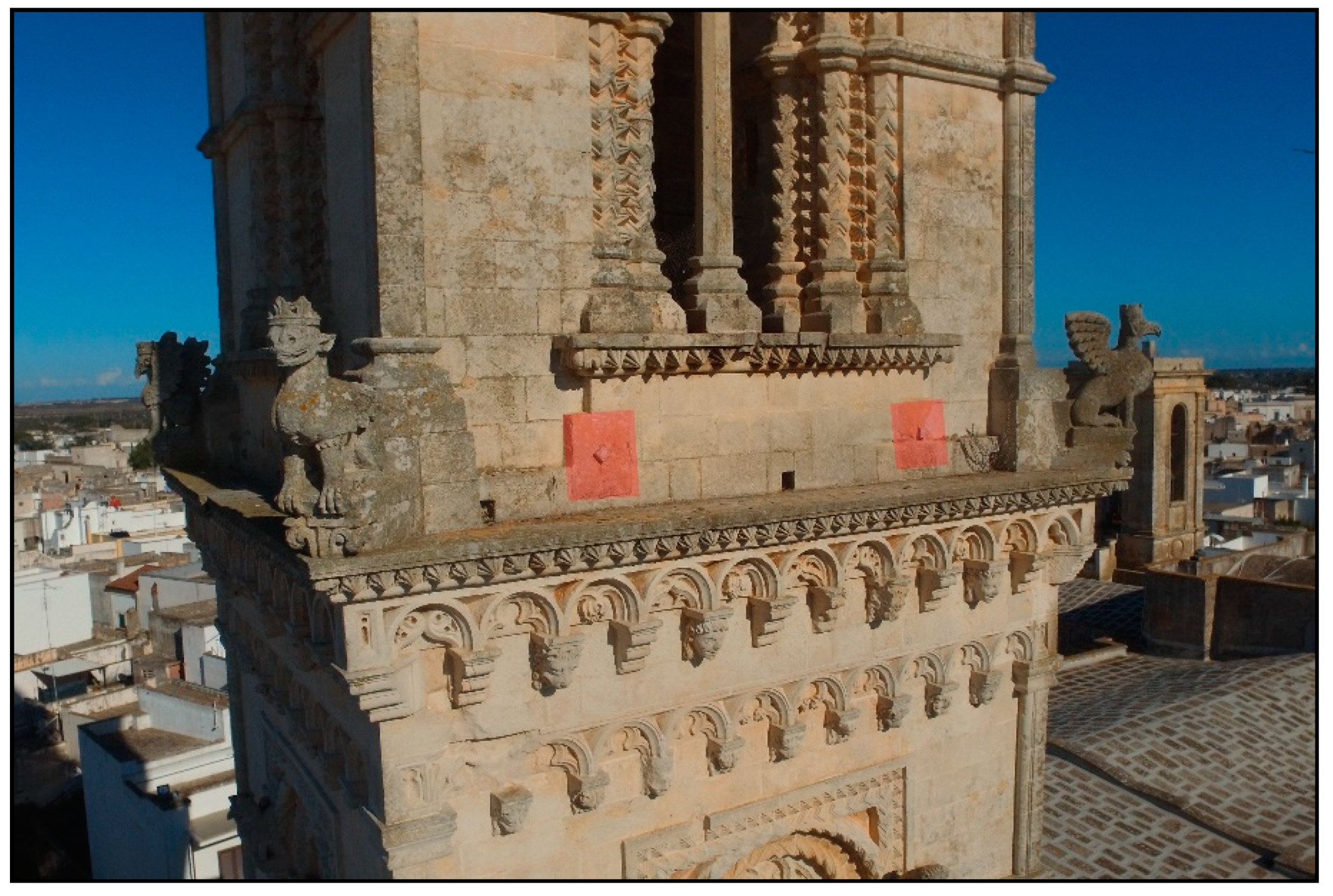
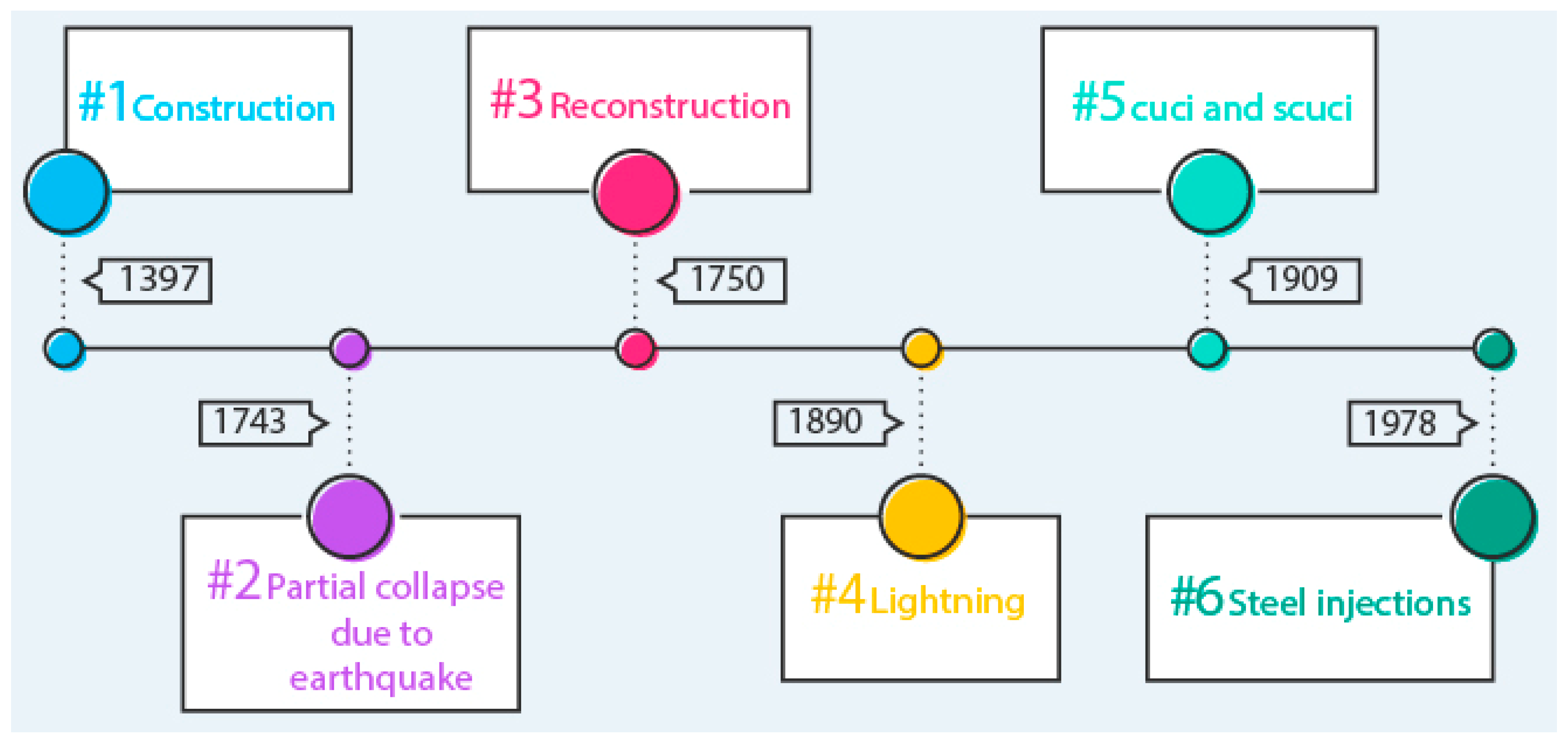
In 1743, an earthquake caused the upper part of the tower to collapse, which was later rebuilt in 1750 [12]. In 1781, the church was demolished and rebuilt: the new facade was added side-by-side the bell tower. In 1837, a cuci and scuci intervention (i.e., sew and untwist) affected the tower. In 1909, diffuse crack pattern made the stitching operations necessary. In addition, in the same year, steel ties were installed along the two orthogonal directions of the third and fourth order of the tower (see Figure 2).
In 1978, a cause of subsidence of the laying ground, a series of foundation micro piles were created to consolidate the ground. In the same year the masonry was consolidated by means of steel injections with cement-based mixes, an intervention which proved to be worse over time for the building. In fact, the corrosion of the metal bars largely manifested, [13]. Finally, the advanced level of decay of the masonry was resolved, in 1993, through the treatment of the surface: cleaning and water-repellent patina. The timeline relating to the structural milestones for the Soleto’s bell tower is shown in Figure 3.

2. Drone-Assisted Survey

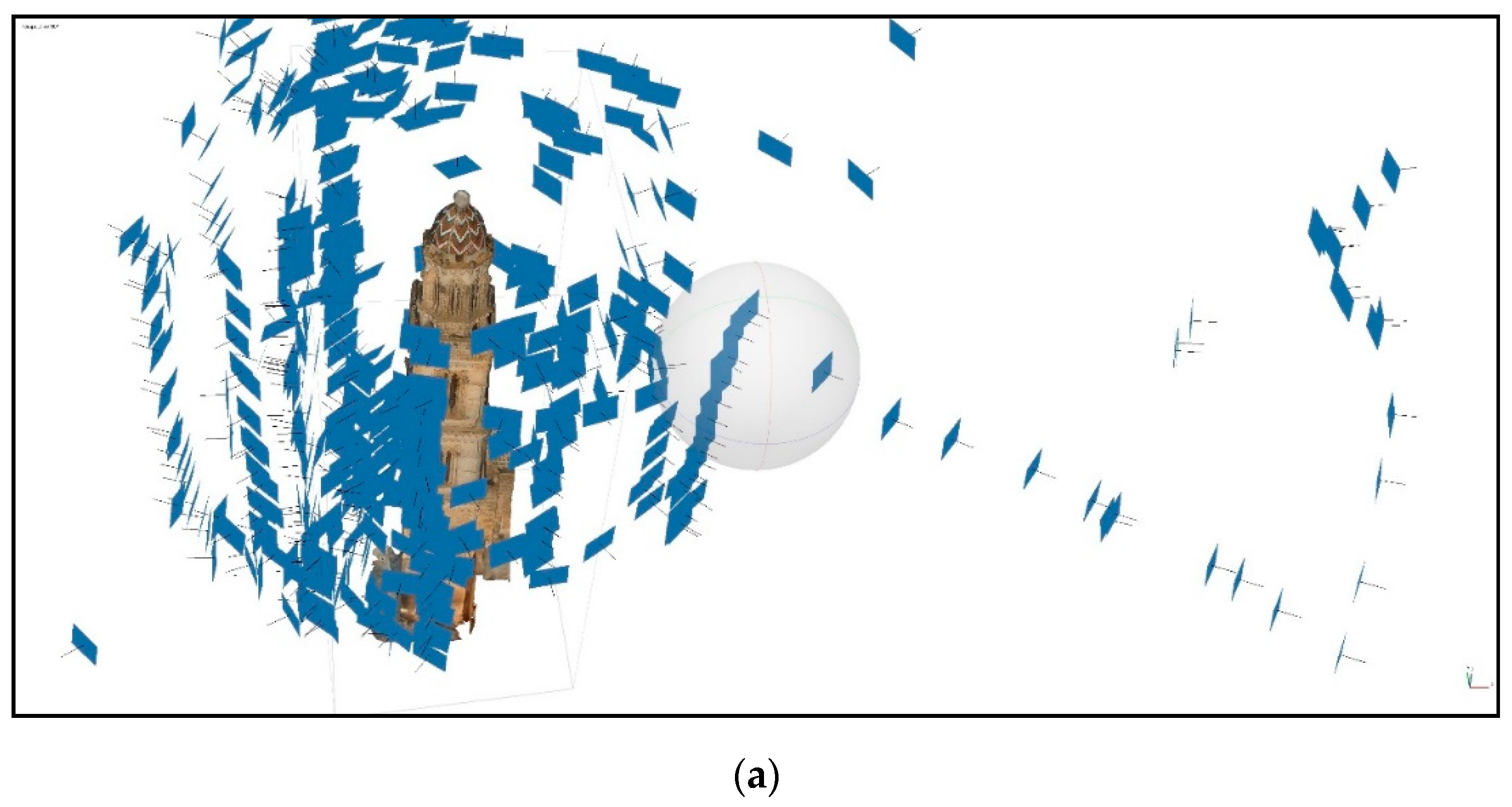
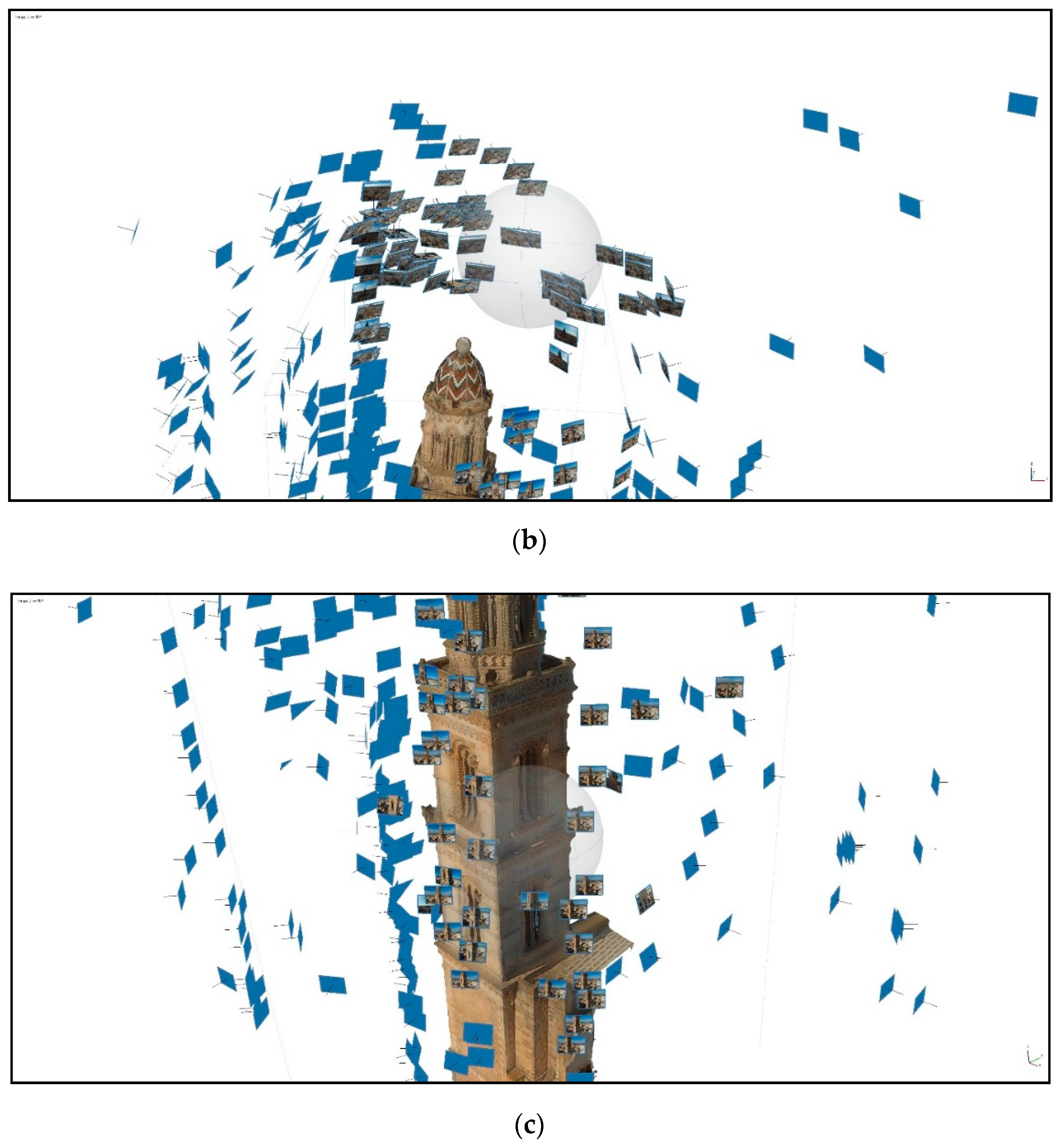
The geometrical and structural survey of the tower was made by a drone-assisted technique, which allowed us to avoid the use of platforms and scaffolds by performing a time-saving protocol. In this special case, the height of about 40 meters and the impossibility to use stairs form the inside, pushed the authors to perform an innovative technique, using a drone, able to significantly reduce the surveying time. Unmanned aerial vehicle (UAV) as a supplementary bridge damage quantification tool has already been experienced and proposed nowadays, as reported in [14]. In this case the study was extended to a heritage building, with a more complex geometry. The digital model, associated to a fly scheduling related to the geometry of the object, was implemented with advanced digital imaging tools, as also described in [15,16]. In this case a three-dimensional photo-realistic model was obtained, comparable to those results shown in previous studies [17,18,19]. A total of 600 photos of the bell-tower have been shot (see Figure 4a–c). Global Positioning System metadata were associated with each relative photo. Indoor flight was not allowed because the tower has no access, so it can be only investigated and touched outdoors. The wall cross-sections were computed according to available past geometrical surveys.
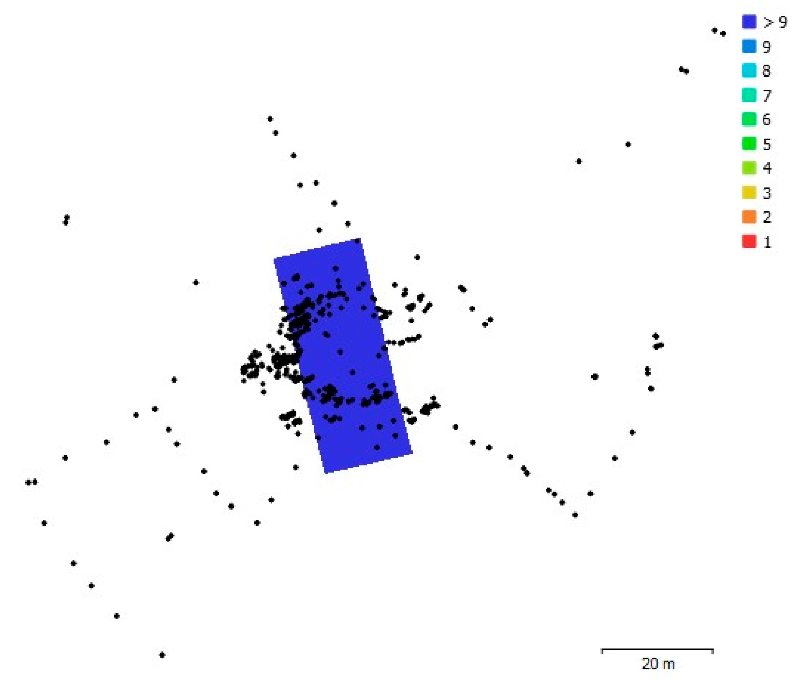
The photos were taken at an average altitude of 18.2 m ± 14.5 m with a ground resolution of 3.82 mm/pix. The coverage area was equal to 651 m2. The camera had a 4000 × 2250 pix resolution (pix size = 1.7 × 1.7 µm) and a focal length of 3.61 mm. As a result, the point density was 1.71 points/cm2. The camera location and the image overlap are illustrated in Figure 5. A schematic patter for the flights is not mandatory.
The full-scale model was built by using a computer graphic software (namely Agisoft Metashape, St. Petersburg, Russia), able to join the digital photos and unify all the inputs into a full-scale model, by following a step-by-step automated procedure, as shown in Figure 6 [20]. Image processing was performed by following these steps: loading photos, inspecting loaded images, removing unnecessary images, aligning photos, generating dense point cloud, building mesh (3D-polygonal model), generating texture and building “tiled” model as shown in Figure 6e (photo-realistic).
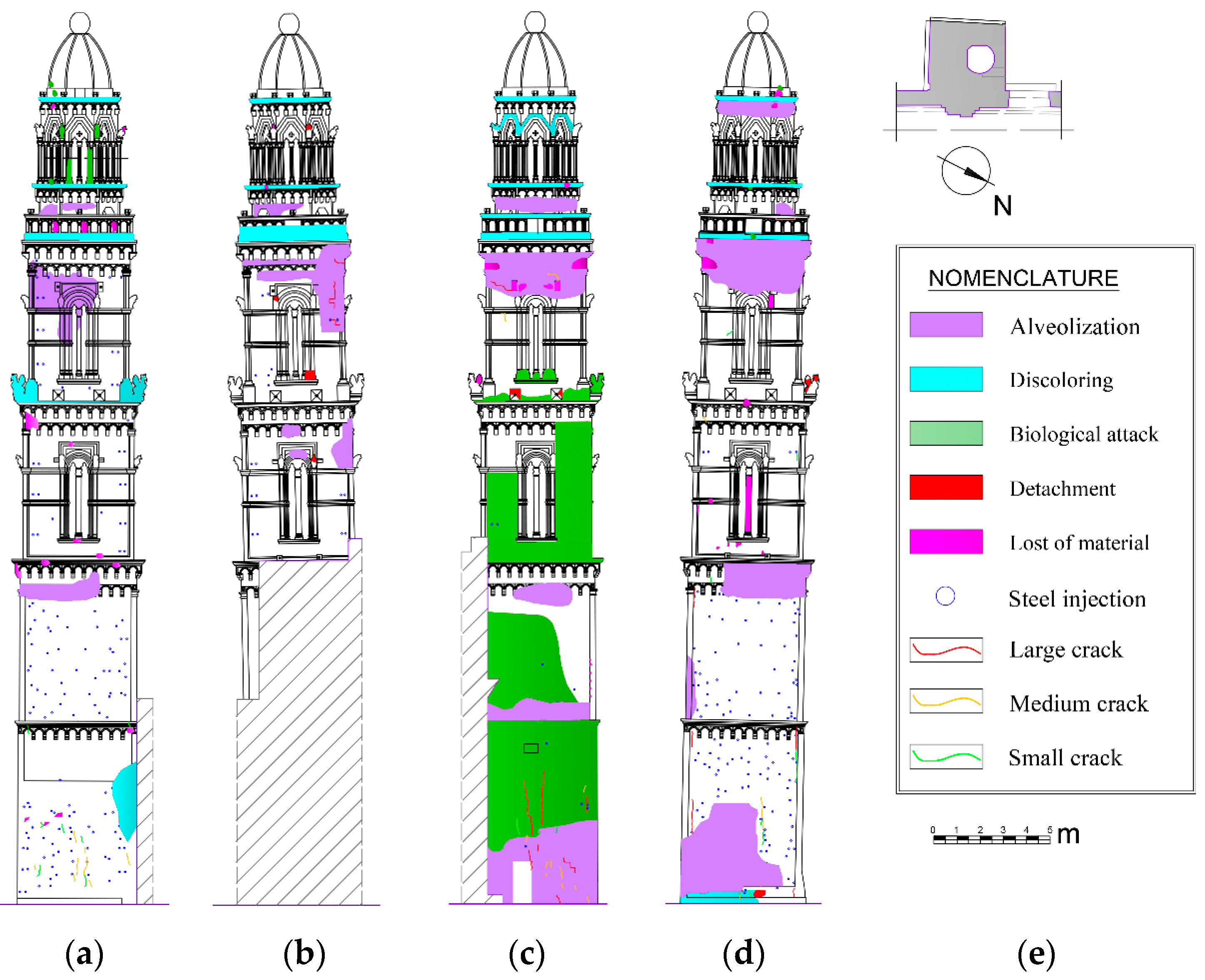
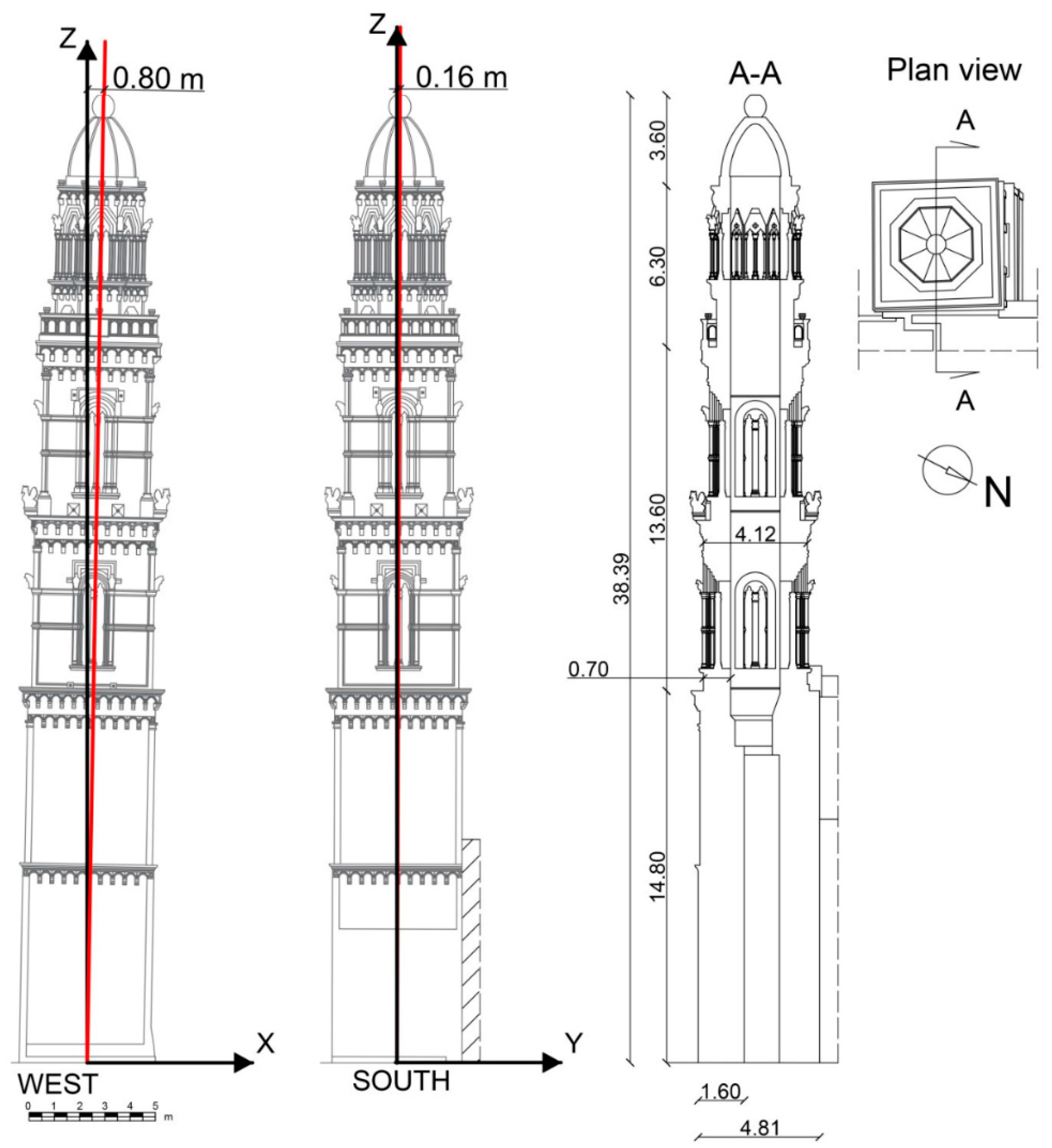
The geometrical survey, available in forms of 3D textured model, as reported in Figure 6e, was useful in order to individuate and allocate all the phenomena that were observed in terms of stone-degradation, material changes, detachments, repair and strengthening interventions performed in the past centuries and decades (see Figure 7 [20]). Moreover, by means of the model obtained in Figure 6d, a verticality defect has been detected and quantified, as reported in Figure 8 [20]. It was measured that the top of the dome was far away from the perfect centroid position. It resulted in a shift of 800 mm and 160 mm in the direction parallel to the main façade of the church and in the orthogonal direction, respectively.

3. Structural Analysis

Structural analyses were performed by using an FEM code, able to perform linear and nonlinear analyses. The numerical investigation included static linear analysis, linear dynamic (modal) analysis, pushover analysis. The MIDAS FEA commercial program [21] was used as numerical code. Masonry was considered as a homogeneous isotropic solid. The constitutive model was based on the total strain method with a smeared crack behavior, as it regards the fracture energy (rotating crack). A damage-plasticity model was assumed for the masonry material, already available in the standard software package for brittle materials. For more details, see the literature available in [22,23]. A three-nodes shell (triangular) model was implemented (area of the bi-dimensional element assumed equal to 0.1 m2). The mechanical behavior of the masonry has been assumed according to the properties reported in Table 1 [20]. Furthermore, a series of spring elements (compression only links) were introduced in the model for simulating the boundary interface between the tower and the construction body of the church, which acts as a constraint for the tower itself.
After the numerical analyses, a nonlinear kinematic analysis was performed, in order to individuate the failure mechanisms, activated by the horizontal seismic forces. The results of the numerical analyses strongly helped to choose those mechanisms that would require the less energy. In this type of analyses, the tower or its sub-parts were assumed as rigid bodies, sustaining on a rigid floor, with infinite strength of the structural materials.

3.1. Linear Dynamic Analysis

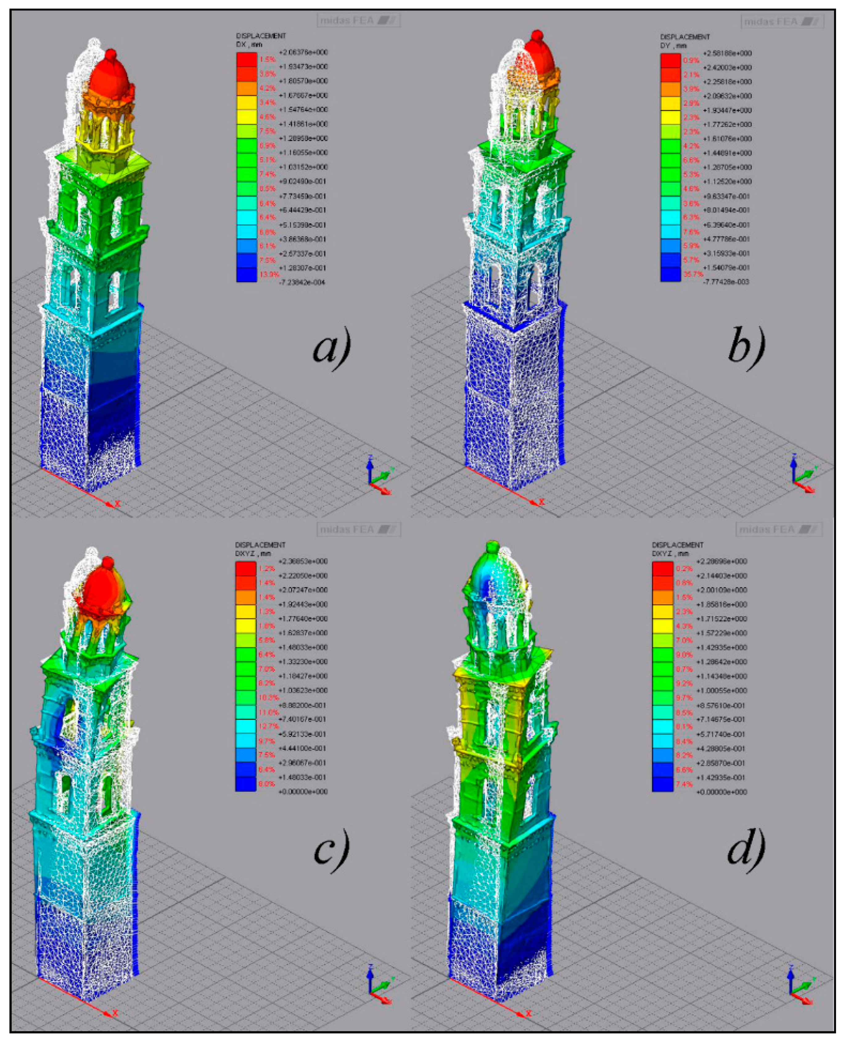
The modal analysis performed the tangent stiffness matrix according to the Newton–Raphson method. In Figure 9 [20]., the first four mode shapes are illustrated. The first modes (mode 1 and 2) were translational, along the principal directions of the tower cross-section; the following modes (mode 3 and 4) were torsional. The results of the dynamic analysis in terms of frequencies, periods and participating mass are collected in Table 2 [20]. The fundamental period resulted equal to 0.71 s. Moreover, it was stated that the sum of the participating masses of the 12 X-displacement modes was equal to 87.23%.

3.2. Nonlinear Static Analysis (Pushover)

The pushover analysis consisted in the application of the dead loads and a representative incremental lateral load pattern. The increment of the pushing load is continued until a damage surface, able to induce possible tower overturning, was recognized. The lateral displacement was imposed incrementally following the arc-length iterative method in combination with the initial stiffness method. The convergence criterion was controlled through a displacement and energy norm ratio equal to 0.005 and 0.001, respectively. The results were expressed in forms of base shear vs. top displacement values. This was obtained for the four analyses, as reported in Figure 10 [20]: +X, −X, +Y, −Y directions. It is evident that the shear elastic stiffness is comparable in +X and −Y directions (due to symmetry); while a significant difference is evident in +Y-direction due to the different boundary conditions. Furthermore, the less vulnerable direction resulted to be the −X because the lateral force resulted applied in opposition to the defect of verticality. On the contrary, the highest vulnerability was assessed along the +X direction, in fact, in this case the lateral force is concurrent with the vertical defect. The behavior in –Y direction was almost comparable with the +X. This can be explained by the fact that that in such direction the tower has a wall shorter than the others.
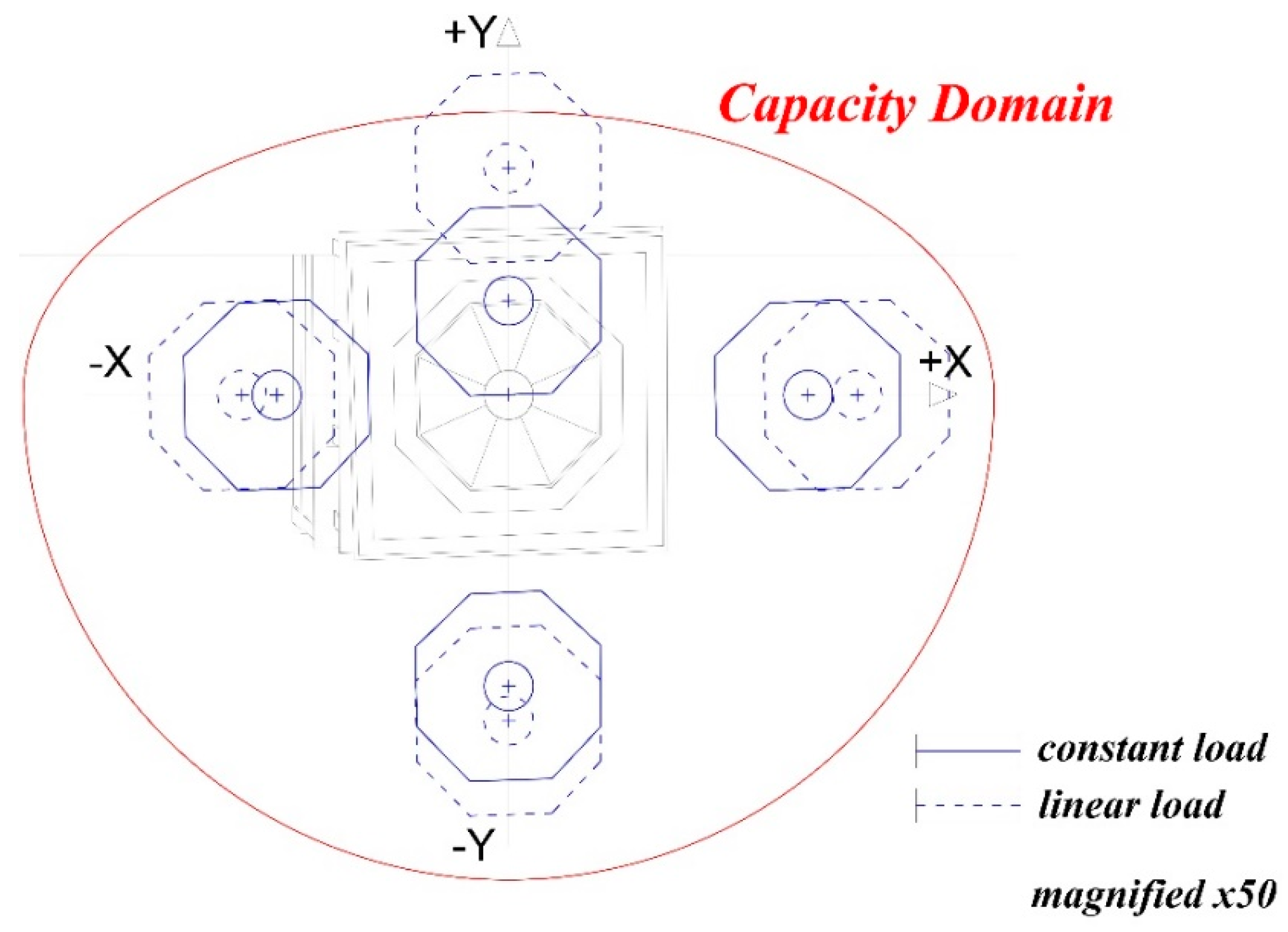
However, the displacement capacity verifications were all satisfied (see Figure 11 which is x50 magnified in term of displacements), and it was possible to observe that the shear strength is comparable in the +X and −Y directions (cause of symmetry), while a significant difference is evident in the +Y direction due to the influence of the boundary conditions and the different thickness and materials of the model. The least vulnerable direction was found to be the −X because the lateral force acted in opposition to the imperfection of verticality, while the greatest vulnerability was found in the +X direction, in fact, in this case the lateral force required less energy to push the structure, which already had a significant inclination in that direction. The maximum positive and negative displacements in both X and Y axis in Figure 11 are in accordance with Figure 10.

3.3. Kinematic Linear Analysis

A linear kinematic analysis was performed in order to define the ultimate displacement capacity of the tower, when it is considered as an equivalent oscillator corresponding to the values for which the acceleration is null. The simple hypotheses of the method are listed herein:
  • the compressive strength of masonry is infinite;
  • the tensile strength of masonry is null;
  • the sliding between the block is forbidden by the method;
  • masonry acts as an assemblage of rigid blocks which means that the collapse is due to the formation of a sufficient number of hinges between the blocks themselves.
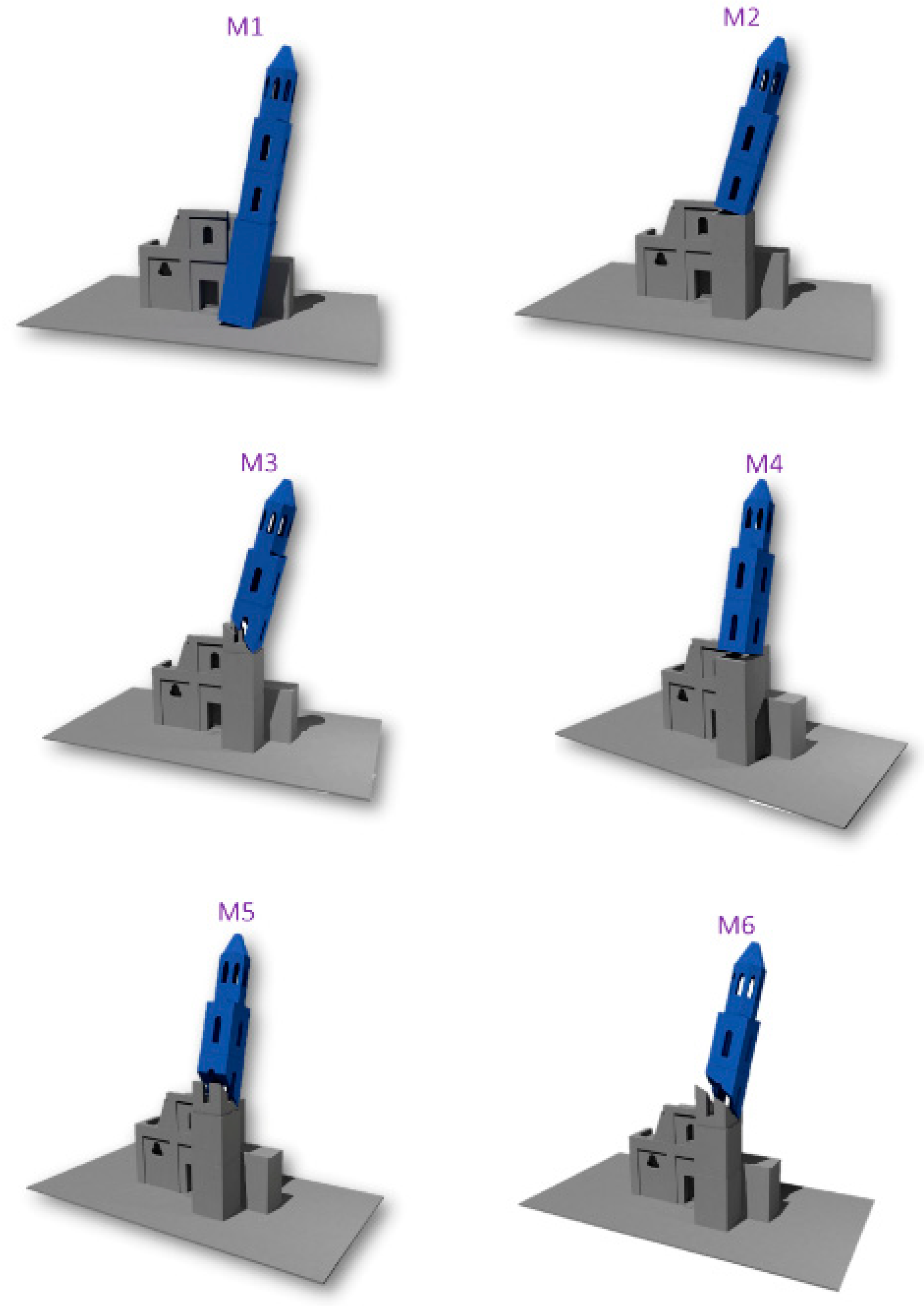
This type of rigid-body analysis is commonly used for the limit analysis of masonry buildings, due to their attitude to manifest equilibrium problems due to global stability instead of cracking or crisis of materials. In this perspective masonry buildings are governed mostly by the rules of the geometrical proportion between the sub-structural systems. The ultimate configuration of equilibrium is governed by the possible rotation of blocks around hinges. The main mechanisms for masonry towers are exhaustively described in [24]. In particular, six possible mechanisms have been considered (see Figure 12 [20]), such as:
  • M1—Total tower overturning with respect to the X-direction. The fracture plane is horizontal, and the rotation performs around a cylindrical hinge;
  • M2—Half tower overturning with respect to the X-direction. The fracture plane is horizontal, and the rotation performs around a cylindrical hinge;
  • M3—Half tower overturning with respect to the X-direction. The fracture plane is inclined, and the rotation performs around a cylindrical hinge;
  • M4—Half tower overturning with respect to the Y-direction. The fracture plane is horizontal, and the rotation performs around a cylindrical hinge;
  • M5—Half tower overturning with respect to the Y-direction. The fracture plane is inclined, and the rotation performs around a cylindrical hinge;
  • M6—Half tower overturning with respect to the diagonal of the cross-section. The fracture plane is inclined, and the rotation performs around a spherical hinge.
Similar to the nonlinear static analysis, the study of the local mechanisms provides a capacity curve with a pseudo-linear trend by considering the equivalent SDOF system (single degree of freedom). The target value is represented by the maximum displacement that the building can exhibit before the collapse.
The recognition of the failure mechanism is quantified by comparing the expected acceleration and the acceleration that is able to activate the mechanism. Whereby, the safety criterion is graphically illustrated in Figure 13 in terms of demand/capacity ratios concerning displacements. As evident, the M3 mechanism was not satisfied according to the peak ground acceleration of the considered site, due to the insufficient displacement capacity with respect to the relative demand.

4. Conclusions

The structural assessment and seismic vulnerability of heritage masonry buildings, such as slender towers, is often a complicated task for structural engineers. The uncertainties related to the geometry and materials, which reflects non-linearity behavior, inhomogeneity, constraints modelling, etc., need an accurate survey. In this research a case study regarding an ancient masonry bell-tower has been described. The main goal was to assess the capacity of the building against to lateral seismic forces. The novelty of the research consists of a new drone-assisted technique used for the geometrical and structural survey as previously reported in [25]. The results of the digital survey were ready to be implemented into a commercial FEM code. Thus, a strict connection was implemented between the surveying and FEM-analysis phases.
However, the bell-tower is placed in a low seismicity area, and the results of the study evidenced the vulnerability of the structure, mainly due to its verticality defect. The possible failure would consist in a middle-height overturning mechanism, favored by the vertical defect, due to foundation settlements occurred after the original construction.

Author Contributions

Conceptualization, A.C. and F.M.; methodology, A.C.; software, F.M.; validation, M.A.A.; formal analysis, F.M.; investigation, A.C.; resources, F.M.; data curation, A.C.; writing—original draft preparation, A.C.; writing—review and editing, M.A.A.; visualization, F.M.; supervision, M.A.A.; project administration, F.M.; funding acquisition, F.M. All authors have read and agreed to the published version of the manuscript.

Funding

This research received no external funding.

Acknowledgments

The authors wish to kindly thank to the Italian Ministry of the Cultural Heritage (MiBAC—Ministero per I Beni e le Attività Culturali) and the Superintendence of the municipality of Lecce for the availability and interest shown during the development of this research study. The authors also thank the CSPFea company for the technical support in developing the structural model within the MIDAS FEA code.

Conflicts of Interest

The authors declare no conflict of interest.

References

  1. Ferraioli, M.; Miccoli, L.; Abruzzese, D.; Mandara, A. Dynamic characterisation and seismic assessment of medieval masonry towers. Nat. Hazards 2017, 86, 489–515. [Google Scholar] [CrossRef]
  2. Saisi, A.; Gentile, C.; Guidobaldi, M.; Xu, M. Dynamic monitoring and seismic response of a historic masonry tower. Key Eng. Mater. 2014, 628, 55–60. [Google Scholar] [CrossRef]
  3. Facchini, L.; Betti, M. Simplified seismic analysis of disordered masonry towers. ASCE-ASME J. Risk Uncertain. Eng. Syst. Part A Civ. Eng. 2016, 2, C4015010. [Google Scholar] [CrossRef]
  4. Peña, F.; Lourenço, P.B.; Mendes, N.; Oliveira, D.V. Numerical models for the seismic assessment of an old masonry tower. Eng. Struct. 2010, 32, 1466–1478. [Google Scholar] [CrossRef] [Green Version]
  5. Fragonara, L.Z.; Boscato, G.; Ceravolo, R.; Russo, S.; Ientile, S.; Pecorelli, M.L.; Quattrone, A. Dynamic investigation on the Mirandola bell-tower in post-earthquake scenarios. Bull. Earthq. Eng. 2016, 15, 313–337. [Google Scholar] [CrossRef] [Green Version]
  6. Diaferio, M.; Foti, D. Seismic risk assessment of Trani’s Cathedral bell-tower in Apulia, Italy. Int. J. Adv. Struct. Eng. 2017, 9, 259–267. [Google Scholar] [CrossRef] [Green Version]
  7. Bartoli, G.; Betti, M.; Vignoli, A. A numerical study on seismic risk assessment of historic masonry towers: A case study in San Gimignano. Bull. Earthq. Eng. 2016, 14, 1475–1518. [Google Scholar] [CrossRef]
  8. Bernardeschi, K.; Padovani, C.; Pasquinelli, G. Numerical modelling of the structural behaviour of Buti’s bell-tower. J. Cult. Herit. 2004, 5, 371–378. [Google Scholar] [CrossRef]
  9. Acito, M.; Bocciarelli, M.; Chesi, C.; Milani, G. Collapse of the clock tower in Finale Emilia after the May 2012 Emilia Romagna earthquake sequence: Numerical insight. Eng. Struct. 2014, 72, 70–91. [Google Scholar] [CrossRef]
  10. Valente, M.; Milani, G. Non-linear dynamic and static analyses on eight historical masonry towers in the North-East of Italy. Eng. Struct. 2016, 114, 241–270. [Google Scholar] [CrossRef]
  11. D’Ambrisi, A.; Mariani, V.; Mezzi, M. Seismic assessment of a historical masonry tower with nonlinear static and dynamic analyses tuned on ambient vibration tests. Eng. Struct. 2012, 36, 210–219. [Google Scholar] [CrossRef]
  12. Rossetti, P. Maria SS.ma Assunta–Soleto; Editrice Salentina: Lecce, Italy, 2011. (In Italian) [Google Scholar]
  13. Rizzo, T. Restauri Satanici, Tipografia; G. Capponi srl–Firenze: Florence, Italy, 1994. (In Italian) [Google Scholar]
  14. Duque, L.; Seo, J.; Wacker, J. Bridge Deterioration Quantification Protocol Using UAV. ASCE J. Bridge Eng. 2018, 23, 04018080. [Google Scholar] [CrossRef]
  15. Burger, W.; Mark, J. Burge, Digital Image Processing: An Algorithmic Approach Using Java; Springer: Berlin/Heidelberg, Germany, 2007; ISBN 978-1-84628-379-6. [Google Scholar]
  16. Fortunato, G.; Funari, M.F.; Lonetti, P. Survey and seismic vulnerability assessment of the Baptistery of San Giovanni in Tumba (Italy). J. Cult. Herit. 2017, 26, 64–78. [Google Scholar] [CrossRef]
  17. Ridolfi, E.; Buffi, G.; Venturi, S.; Manciola, P. Accuracy analysis of a dam model from drone surveys. Sensors 2017, 17, 1777. [Google Scholar] [CrossRef] [PubMed] [Green Version]
  18. Barrile, V.; Bilotta, G.; D’Amore, E.; Meduri, G.M.; Trovato, S. Structural modeling of a historic castle using close range photogrammetry. Int. J. Math Comput. Simul. 2016, 10, 370–380. [Google Scholar]
  19. Marmo, F.; Demartino, C.; Candela, G.; Sulpizio, C.; Briseghella, B.; Spagnuolo, R.; Rosati, L. On the form of the Musmeci’s bridge over the Basento river. Eng. Struct. 2019, 191, 658–673. [Google Scholar] [CrossRef]
  20. Micelli, F.; Cascardi, A. Structural assessment and seismic analysis of a 14th century masonry tower. Eng. Fail. Anal. 2020, 107, 104198. [Google Scholar] [CrossRef]
  21. Midas FEA. Advanced Nonlinear and Detail Program. Analysis and Algorithm. 1989. Available online: https://en.midasuser.com/product/fea_overview.asp (accessed on 8 July 2020).
  22. Thorenfeldt, E.; Tomaszewicz, A.; Jensen, J.J. Mechanical properties of high-strength concrete and applications in design. In Proceedings of the Symposium Utilization of High-Strength Concrete, Stavanger, Norway, 15–18 June 1987; Tapir: Trondheim, Norway, 1987. [Google Scholar]
  23. Cornelissen, H.A.W.; Hordijk, D.A.; Reinhardt, H.W. Experimental determination of crack softening characteristics of normalweight and lightweight concrete. Heron 1986, 31, 2. [Google Scholar]
  24. Sarhosis, V.; Milani, G.; Formisano, A.; Fabbrocino, F. Evaluation of different approaches for the estimation of the seismic vulnerability of masonry towers. Bull. Earthq. Eng. 2017, 16, 1511–1545. [Google Scholar] [CrossRef] [Green Version]
  25. Micelli, F.; Cascardi, A.; Aiello, M.A. Seismic behavior of a masonry bell-tower with verticality defect. In Proceedings of the Euro-American Congress REHABEND 2020 on Construction Pathology, Rehabilitation Technology and Heritage Management, Granada, Spain, 24–27 March 2020. [Google Scholar]
Figure 1. Bird’s eye view of the Soleto’s bell-tower.
Infrastructures 05 00072 g001
Figure 2. Detail of steel ties.
Infrastructures 05 00072 g002
Figure 3. Timeline of the significant events modifying the architectural aspect and the structural behavior of the Soleto’s bell-tower.
Infrastructures 05 00072 g003
Figure 4. Drone catches of the bell tower: (a) global view; (b) dome and (c) main body.
Infrastructures 05 00072 g004aInfrastructures 05 00072 g004b
Figure 5. Camera locations and image overlap.
Infrastructures 05 00072 g005
Figure 6. Computer graphical elaboration of the bell-tower: (a) point cloud, (b) dense cloud, (c) wireframe, (d) mesh, (e) textured.
Infrastructures 05 00072 g006
Figure 7. Status of the bell-tower: (a) South, (b) East, (c) North, (d) West and (e) plan view.
Infrastructures 05 00072 g007
Figure 8. Inclination of the bell-tower relief (left) and longitudinal section (right)—all dimensions in meters.
Infrastructures 05 00072 g008
Figure 9. Modal shapes: (a) X-translation; (b) Y-translation; (c) global X-rotation and (d) global Z-rotation.
Infrastructures 05 00072 g009
Figure 10. Capacity curves from pushover analysis (total weight of the tower equal to 8904 kN).
Infrastructures 05 00072 g010
Figure 11. Capacity domain from pushover analysis.
Infrastructures 05 00072 g011
Figure 12. Draft of the failure mechanisms of the bell-tower.
Infrastructures 05 00072 g012
Figure 13. Non-linear kinematic analysis: capacity curves.
Infrastructures 05 00072 g013
Table 1. Masonry properties.
VariableTuffLecce-StoneUnits
Masonry compressive strength5.777.2MPa
Masonry tensile strength0.500.70MPa
Masonry shear strength0.80.9MPa
Young’s modulus21973360MPa
Shear modulus7291120MPa
Weight density1622kN/m3
Table 2. Masonry properties.
ModeFrequency [rad/sec]Period [sec]Participating Mass [%]Description
15.6441.11359.26X-translation
27.8510.80052.23Y-translation
316.3730.38468.41Global X-rotation
418.2340.34577.17Global Z-rotation