Abstract
Transportation infrastructure is critical for the advancement of society. Bridges are vital for an efficient transportation network. Bridges across the world undergo variable deformation/displacement due to the Earth’s dynamic processes. This displacement is caused by ground motion, which occurs from many natural and anthropogenic events. Events causing deformation include temperature fluctuation, subsidence, landslides, earthquakes, water/sea level variation, subsurface resource extraction, etc. Continual deformation may cause bridge failure, putting civilians at risk, if not managed properly. Monitoring bridge displacement, large and small, provides evidence of the state and health of the bridge. Traditionally, bridge monitoring has been executed through on-site surveys. Although this method of bridge monitoring is systematic and successful, it is not the most efficient and cost-effective. Through technological advances, satellite-based Persistent Scatterer Interferometry (PSI) and Geographic Information Systems (GIS) have provided a system for analyzing ground deformation over time. This method is applied to distinguish bridges that are more at risk than others by generating models that display the displacement at various locations along each bridge. A bridge’s health and its potential risk can be estimated upon analysis of measured displacement rates. In return, this process of monitoring bridges can be done at much faster rates; saving time, money and resources. PSI data covering Oxnard, California, revealed both bridge displacement and regional ground displacement. Although each bridge maintained different patterns of displacement, many of the bridges within the Oxnard area displayed an overall downward movement matching regional subsidence trends observed in the area. Patterns in displacement-time series plots provide evidence for two types of deformation mechanisms. Long-term downward movements correlate with the relatively large regional subsidence observed using PSI in Oxnard. Thermal dilation from seasonal temperature changes may cause short-term variabilities unique to each bridge. Overall, it may be said that linking geologic, weather, and groundwater patterns with bridge displacement has shown promise for monitoring transportation infrastructure and more importantly differentiating between regional subsidence and site-specific displacements.
1. Introduction
Within recent history, researchers have embarked on a road to find a more efficient system to monitor the displacement/deformation of infrastructures around the world. The most common method of monitoring bridges currently involves repeated visual inspections of the exterior condition of bridges. This method of monitoring restricts complete structural analysis due to the limited amount of information it provides [1]. While visual inspection delivers a detailed assessment of the external health of bridges, it fails to reveal vital information concerning the internal health of bridges and is laborious. Only a few bridges around the world have site-based instrumentation, which includes surface or embedded sensors [2]. In other words, most bridges and other human-made structures across the globe lack continuous structural inspection.
Recent developments have highlighted the application of Unmanned Aerial Vehicles (UAV) or Unmanned Aircraft Systems (UAS) and Structure from Motion (SfM) for quantitative monitoring of infrastructure [3,4,5,6,7]. The UAS systems use different sensors including optical, thermal, and Light Detection and Ranging (LiDAR) to quantify the infrastructure condition. Although the UAS systems are valuable in monitoring individual bridges, these methods are not suitable when regional processes need to be understood to explain the behavior of infrastructure in a region. While monitoring of individual infrastructure is critical, the regional-scale monitoring of infrastructure is hypercritical for land use planning and sustainable development. Studies have shown the application of satellite-based Interferometric Synthetic Aperture Radar (InSAR) for monitoring bridges and critical infrastructure as well as regional-scale displacement from tectonics and other processes [8,9,10,11,12]. This study builds on those efforts to demonstrate how InSAR based (particularly Persistent Scatterer Interferometry (PSI)) monitoring and Geographic Information System (GIS) based analysis can be helpful to understand the performance of an individual infrastructure as well as evaluate whether regional scale processes control these performances.
2. Background
Visual inspection is the default approach to monitoring of bridges [1]. An FHWA report [1] summarized the limitation of visual inspection. The fundamental limitations being the timing, subjectivity, and accessibility [1]. In the past years, there have been several Structural Health Monitoring (SHM) methods developed for bridge monitoring [13,14]. These methods include the use of strain gauges, accelerometers, load testing, and displacement measurements.
In many cases, it is meaningful to monitor displacement to detect structural damage. However, measuring displacement can be problematic because of the need for stable reference points. The use of remote sensing based methods from aerial and satellite-based platforms provide a vital solution for measuring the displacement of bridges [15,16,17,18]. When the displacement of a bridge is measured, it can be from structural deficiencies of the bridge or regional ground subsidence. Therefore, displacement measurement of bridges and other critical infrastructure must be compared with the regional subsidence to verify the cause for the displacement.
This study focuses on the use of ENVISAT C-band Synthetic Aperture Radar (SAR) data, which has been collected for the area encompassing Oxnard, California. The impetus behind this work was established from a study for the mapping of slow landslides on Palos Verdes Peninsula using PSI [19]. Satellite-based radar sensors provide millimeter-level displacement monitoring, and coverage over large areas, with the ability to collect data during all weather conditions, day or night [20]. Further detail and explanation of PSI technicalities can be found in the SAR-Guidebook [21,22,23]. With this application, the continually changing ground conditions on earth and human-made structures across the world may be monitored with applied differentiation between ground subsidence and site-specific bridge/infrastructure deformation. The topics that will be covered include analysis of ENVISAT data, the sensitivity of SAR measurements, the use of ArcGIS for modeling and interpretation, land subsidence due to groundwater pumping in California, and cause of bridge displacement through regional displacement.
3. Study Location
The city of Oxnard is located along the coast of southern California, roughly 60 miles west of Los Angeles (Figure 1). Geology of this plain includes a variation of wash, beach, coastal, stream, alluvial, and alluvial fan deposits. These deposits cover the area in an intermingled pattern of units, which consist of various combinations of unconsolidated silt, clay, sand, gravel, as well as submerged silty clay and sand from both aeolian and estuarine environments [24].
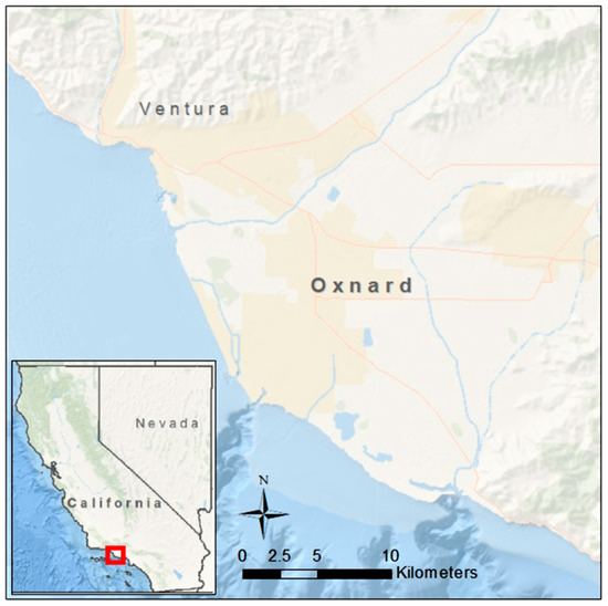
Figure 1.
Map of study area: Oxnard, California. The red box indicates the location of Oxnard within California, corresponding with the close up view of Oxnard.
Forwarding to more recent geologic history, California has been facing subsurface deformation due to several anthropogenic events. These events include, peat loss, oil extraction, and groundwater pumping, which cause land subsidence. The primary causes for land subsidence across the world include aquifer-system compaction, drainage of organic soils, underground mining, hydro-compaction, natural compaction, sinkholes, and thawing permafrost [25]. The leading cause for land subsidence in the Oxnard plains of California is excessive groundwater pumping. Historically, high rates of subsidence have been recorded to be more than 1 foot per year. Although there have been attempts to recover the aquifers, which decreased the subsidence in this area, subsidence continues to occur today [26].
4. Data
4.1. Radar Imagery
Twenty-three descending, single-look complex (SLC) synthetic aperture radar (SAR) images were acquired from the Advanced SAR (ASAR) sensor onboard the ENVISAT satellite (operated by the European Space Agency) between August 2005 and January 2010. These ENVISAT data were processed using PSI, a radar stacking technique capable of measuring ground deformation with an accuracy of 1 mm/year [27,28,29]. Processing was performed following the five-step Interferometric Stacking PS workflow in ENVI SARscape using default input parameters for ERS-1/-2 and ENVISAT SAR data [22]. Ground deformation results (e.g., displacement and velocity) include a positive or negative sign to indicate vector direction: positive deformation is towards the satellite (either upward or significantly to the east) and negative deformation is away from the satellite (either downward or significantly to the west). PSI has successfully measured ground deformation across a myriad of geotechnical structures and assets, including buildings [30,31,32], dams and reservoirs [33,34,35], bridges [36,37,38,39,40,41], and unstable slopes [42,43,44,45,46].
4.2. Bridges
Figure 2 is a schematic of the method followed in this study to monitor the impact of groundwater pumping on bridges. In summary, bridges that showed the most displacement with patterns that could be of concern were sought out. For example, if a bridge is exhibiting high rates of displacement on one end while the opposite end is experiencing little to no movement, a number of structural issues could arise.
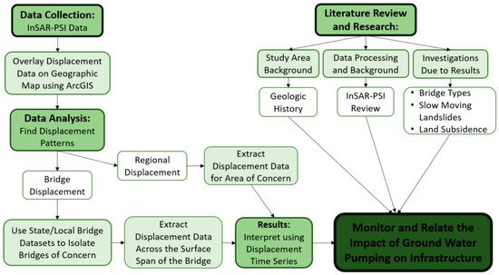
Figure 2.
Chart summarizing the steps taken throughout the research process for monitoring the impact of groundwater pumping on infrastructure using GIS and PSI.
Three bridges that display asymmetrical patterns of differential displacement have been detected. Santa Clara River Bridge is a pre-stressed concrete continuous box beam/girder bridge, spanning the length of 230.2 m, with a width of 58.0 m. This bridge lies on the northern edge of Oxnard, serving as a connection to Ventura California, over the Santa Clara River. Pleasant Valley Road Overcrossing is also a pre-stressed concrete continuous box beam/girder bridge, which spans a length of 77.9 m, with a width of 26.3 m. This bridge lies on the southeast edge of Oxnard, serving as an overcrossing for South Rice Avenue. The final bridge displaying noticeable displacement in the Oxnard area is the Third Street Overcrossing. This bridge along with the others is a pre-stressed concrete continuous box beam/girder bridge, which spans the length of 202.4 m with a width of 22.3 m. This bridge is located in the heart of Oxnard, serving as an overcrossing for South Oxnard Boulevard. The location, dimensions, and type of these bridges was found using Caltrans, Structure Maintenance & Investigations, Log of Bridges on State Highways (SM & ILBSH) [47].
To compare the patterns seen in the bridges of concern to those that are not of concern, three bridges were analyzed that display patterns with little movement. Victoria Avenue Overcrossing is a concrete continuous box beam/girder bridge, spanning the length of 90.2 m, with a width of 33.5 m. This bridge lies just inside the northwest boundary of land subsidence displayed in Figure 3, which is just northwest of the Santa Clara River Bridge. Seaward Avenue Overcrossing is a pre-stressed concrete continuous box beam/girder bridge, which spans the length of 68.6 m, with a width of 32.3 m. This bridge lies just outside the northwest boundary of land subsidence (Figure 3), less than a mile from the coast. The last bridge analyzed was the Carmen Drive Overcrossing. This bridge is also characterized as a pre-stressed concrete continuous box beam/girder bridge, spanning a length of 60.0 m, with a width of 26.2 m. Carmen Drive Overcrossing is located within the east boundary of land subsidence, just south of an area that is not experiencing land subsidence (Figure 3). The location, dimensions, and type of these bridges was also found using Caltrans, (SM & ILBSH) [47].
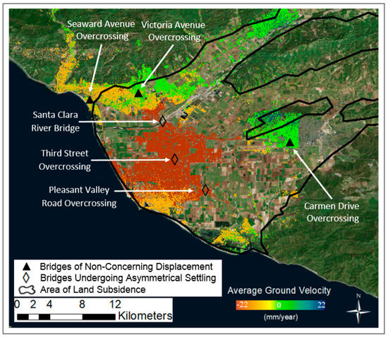
Figure 3.
Regional displacement velocity map, made using ArcGIS. Colored scale indicates the average ground displacement velocity across Oxnard, CA. White arrows indicate the bridges of focus. The area within the black line is the area experiencing land subsidence.
5. Methodology
The main elements of the bridge displacement detection include the following steps. InSAR PSI data, which covered the Palos Verdes Hills, and Oxnard area along the southwest coast of California was obtained from a study for the mapping of slow landslides on Palos Verdes Peninsula using persistent scatterer interferometry [19]. The next step included organizing and analyzing data from the ENVISAT satellite, using ArcGIS to seek out zones of max ground-displacement. It was found that the Oxnard area, ENVISAT data, displayed the most ground displacement regionally and locally. In order to pin point bridges within these large data sets, polygon files and PSI results, a large point cloud measuring line-of-sight (LOS) deformation at individual persistent scatterers (PS), were overlaid on the map of Oxnard to view the location of locally, and state-owned bridges across the area of study. This file not only displayed the visual and coordinate location of each bridge on ArcGIS, but also included the length and width measurements, number, name, and other various bridge related details. Knowing the name and number of each bridge allowed for defining the types of bridges through state records [47]. Once the local and state bridges were displayed over the InSAR data, large and small ground displacement zones were sought out. In order to provide reasonable evidence of displacement patterns along each of the bridges, bridges were only selected if they obtained ample PS along the bridge. Bridges with scarce PS could provide misleading and uncomprehensive results. Only the PS along the bridge structure were then collected and the data were converted into a text file for further analysis. PS were plotted along each bridge to display the variation in displacement at different points. Subtraction of regional displacement trends from displacement measurements at each bridge allow for the calculation of a local (site-specific) bridge displacement analysis. Finally, the cause of ground displacement can be identified through the regional coverage of ground displacement, and further research of the subsurface geology, hydrogeology, seismic activity, and anthropogenic events.
6. Results and Discussion
6.1. Bridge Displacement
Results displaying the complete PS point cloud, land subsidence area outline, and locations of stable and settling bridges can be seen in Figure 3. Distinguishing between the negative and positive velocity values is important, because each signifies a different direction of ground movement.
The area of interest for this study remained where the bridges were experiencing the most differential movement. As seen in Figure 3, the bridges that displayed noticeable movement were located within the area of highest velocity, while the bridges that displayed more stable conditions were in areas where the velocity of ground movement was minimal. It can be noted that the area displaying highest velocities in Oxnard contains most of Oxnard’s structural development: bridges, buildings, roads, houses and other anthropogenic structures.
Following this analysis, it was seen that each bridge displaying higher displacement velocities had unique patterns of displacement along the span of the bridge. Displacement time series, spanning roughly four years, were plotted in correlation to the span of each bridge, depending on its orientation (Figure 4, Figure 5 and Figure 6). The north-most of these bridges, Santa Clara River Bridge, presents displacement patterns, which indicate that the west-most section of the bridge is moving at greater velocities (~12 mm/year) than the middle and east section of the bridge. With a total displacement measuring at ~20–30 mm more than the middle and east sections of the bridge, the west section measures at ~50 mm total downward displacement within ~4 years. This indicates that the west section of the bridge is experiencing twice the amount of displacement than the east and middle sections of the bridge.
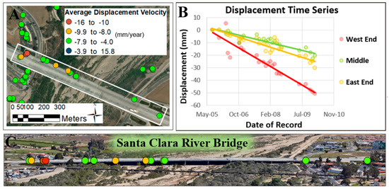
Figure 4.
Santa Clara River bridge displacement model. (A) Aerial view of the bridge; (B) Displacement time series; (C) Elevation view of the bridge. Source: Images for Figure 4A,C were obtained from Google Earth [48].
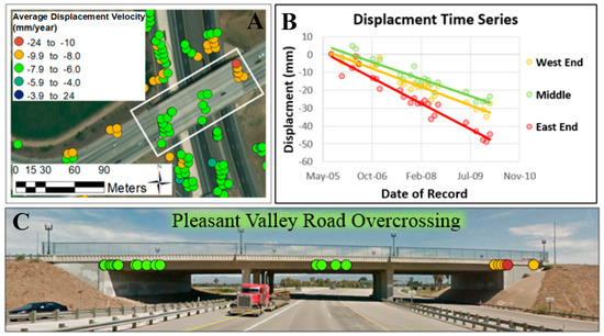
Figure 5.
Pleasant Valley road overcrossing displacement model. (A) Aerial view of the bridge; (B) Displacement time series; (C) Elevation view of the bridge. Source: Images for Figure 5A,C were obtained from Google Earth [48].
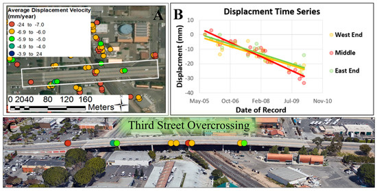
Figure 6.
Third street overcrossing displacement model. (A) Aerial view of the bridge; (B) Displacement time series; (C) Elevation view of the bridge. Source: Images for Figure 6A,C were obtained from Google Earth [48].
The southern-most bridge displaying movement, Pleasant Valley Road Overcrossing, presents displacement patterns indicating that the eastern section of the bridge is moving at a greater velocity (~10 mm/year) than the middle and west section of the bridge. With a total displacement measuring at ~15–25 mm more than the middle and west sections of the bridge, the east section of the bridge measures at ~50 mm total displacement within ~4 years. Similar, but in contrast to the north most bridge, the east section of the bridge is experiencing almost twice the amount of displacement than the middle and west sections of the bridge.
Third Street Overcrossing, the final bridge that displayed movement, is in the center of the high velocity area in Oxnard. This bridge exhibits displacement patterns that indicate that the full length of the bridge is experiencing downward movement. With an average velocity of 6.6 mm/year, reaching max velocities of ~8 mm/year, the bridge returns a total downward displacement average of ~27 mm/year. Although this bridge did not display a large difference in displacement from one section of the bridge to the other, the bridge did reflect a slightly larger displacement in the middle section of the bridge, compared to the west and east sections.
In further examination of the PSI data covering the Oxnard area, regional displacement patterns were observed, which reflected and confirmed the patterns of downward displacement each bridge is experiencing. Although each bridge is experiencing overall downward displacement, they present unique displacement patterns across the bridge itself. These unique displacement patterns discussed above and displayed in Figure 4, Figure 5 and Figure 6 can potentially be linked to structural movement upon each bridge. This was concluded by the minimum downward displacement measured across each bridge. In further explanation, each of the bridges within the high displacement area (Figure 3) are exhibiting a minimum displacement of ~20 mm measured across the bridge, and the regional subsidence reflects a similar average displacement across this high velocity area. The total displacement across the high velocity area of Oxnard is displayed in Figure 7, presenting an average total displacement of 28.6 mm of downward displacement. Therefore, any additional displacement (past ~20–30 mm) across each bridge is potentially due to structural movement. An example of this regional and structural displacement for Santa Clara River Bridge is presented in Table 1. Further investigation is required to determine the overall downward regional displacement trend observed at Oxnard, California.
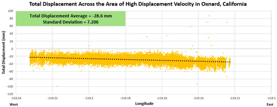
Figure 7.
Total displacement across the area of high displacement velocity in Oxnard, California. Plot displays the trend of total displacement values from the west to the east of the high displacement zone in Oxnard, California. This longitudinal axis is based on GPS location. Total displacement average and standard deviation are indicated in the top left corner.

Table 1.
Distinguishing between regional and site-based/structural displacement along the Santa Clara River Bridge.
6.2. Regional Ground Displacement & Subsidence
Proceeding with the investigation of bridges displaying movement, influences of groundwater pumping presented a direct cause for the overall downward displacement trend occurring in Oxnard, California. Displayed in Figure 3 is the average ground subsidence velocity across Oxnard due to groundwater pumping. The interrelationship between regional displacement and land subsidence in California discloses the idea that regional displacement occurring within the Oxnard area can be linked to land subsidence due to groundwater pumping. Figure 3 further shows the spatial correlation between land subsidence and PSI velocity results: areas that experienced subsidence (orange and red PS) are mapped as such, while relatively stable areas (green PS) are either near the subsidence boundary or outside the mapped subsidence area. Thus, a portion of Oxnard was actively subsiding up to a rate of 22 mm/year between August 2005 and January 2010.
6.3. Stable Bridges
In order to compare unstable bridges to stable bridge conditions, results were generated in similar fashion. Below in Figure 8, Figure 9 and Figure 10 are examples of bridges in the Oxnard area displaying little displacement. Victoria Avenue Overcrossing is a concrete continuous box beam/girder bridge, spanning the length of 90.2 m, with a width of 33.5 m. This bridge lies northwest of the Santa Clara River Bridge in an area presenting velocities ~0–4 mm/year. The average total displacement of this bridge is ~7 mm in the upward direction. Compared to the displacement that bridges are experiencing in the high velocity areas (~20–50 mm downward), this displacement of ~7 mm is considerably small and is in opposite direction.
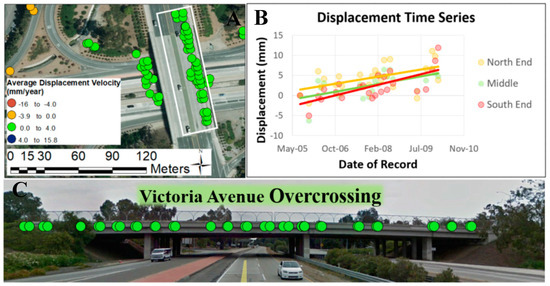
Figure 8.
Victoria Avenue overcrossing displacement model. (A) Aerial view of the bridge; (B) Displacement time series; (C) Elevation view of the bridge. Source: Images for Figure 8A,C were obtained from Google Earth [48].
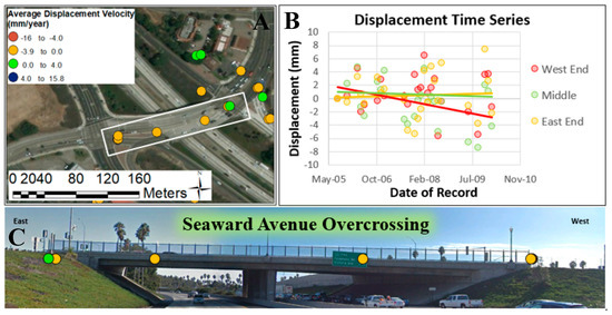
Figure 9.
Seaward Avenue overcrossing displacement model. (A) Aerial view of the bridge; (B) Displacement time series; (C) Elevation view of the bridge. Source: Images for Figure 9A,C were obtained from Google Earth [48].
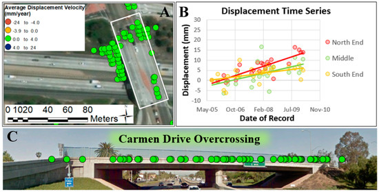
Figure 10.
Carmen Drive overcrossing displacement model. (A) Aerial view of the bridge; (B) Displacement time series; (C) Elevation view of the bridge. Source: Images for Figure 10A,C were obtained from Google Earth [48].
Seaward Avenue Overcrossing is a pre-stressed concrete continuous box beam/girder bridge, spanning 68.6 m in length, with a width of 32.3 m. This bridge also lies just northwest of the Santa Clara River Bridge, roughly 600 m from the coast. It also lies just outside of the area where land subsidence is outlined in Figure 3. It presents velocities of ~0–4 mm/year, and an average total displacement of ~3 mm in the downward direction. The low displacement (~3 mm) that this bridge is experiencing indicates that the bridge is stable.
Carmen Drive Overcrossing is a pre-stressed concrete continuous box beam/girder bridge, spanning 60.0 m in length, with a width of 26.2 m. This bridge lies east outside of Oxnard city limits in Camarillo, CA. It presents velocities of ~0–4 mm/year, and an average total displacement of ~13 mm in the downward direction. The displacement of ~13 mm is less than a third of the magnitude of the bridge displacement in high velocity areas.
The minimal amount of displacement these stable bridges display is in alignment with the regional displacement trends. For example, the Victoria Avenue Overcrossing is located along the outer limits of the land subsidence area (Figure 3) and has significantly lower ground displacements compared to the center of Oxnard.
7. Limitations
Throughout the process of monitoring bridge and regional displacement using GIS and PSI there were a few limitations which caused gaps in data and potential error in the results. As stated, the data covering the Oxnard area were obtained using ENVISAT, which collected radar images with a spatial resolution of ~20 m. The 20-m resolution is quite coarse and utilizing a satellite with better spatial resolution (e.g., COSMO-SkyMed or TerraSAR-X) would increase PS point density. Using a resolution coarser than many bridge components also causes uncertainty as to which part of the bridge is experiencing the measured deformation. The data along just outside of the bridge could be potentially be data collected from the bridge deck, but due to the resolution, there is a chance the data could just be from the beams holding the bridge in place or the surrounding ground below the bridge. Another limiting factor of this method is related to the sensor LOS direction. When the satellite collects its data, it sends a radar beam to the surface of the earth at an incidence angle of ~21° from vertical and at N85°W azimuth direction, limiting the displacement measurements to just the LOS [5]. The last major limiting factor this monitoring method experiences is temporal decorrelation due to significant changes in ground target location, geometry, and geophysical properties. PSI works well over relatively slow-moving areas, experiencing deformation rates less than ~2.5 cm/year; areas experiencing a relatively large deformation will decorrelate due to significant location (X, Y) change between two radar images and are unmeasurable with this technique [5]. Vegetation will also cause decorrelation and create gaps in PS coverage (significant changes in geometry and geophysical properties to ground targets in vegetated areas). As displayed in Figure 3, there are areas where the ENVISAT satellite did not measure ground deformation.
8. Conclusions
The purpose of this paper is to explore the option of using the satellite-based remote sensing data to monitor ground displacement and transportation infrastructure monitoring. PSI technique with ENVISAT imagery was used to measure ground displacement in Oxnard, California, which was used to monitor not only the bridges in Oxnard but also the regional subsidence encompassing the area. Using GIS and PSI data, three of the many bridges displaying movement were further analyzed for displacement patterns along each bridge. The displacement of these bridges as well as bridges displaying more stable conditions demonstrated the regional subsidence that the area of Oxnard is experiencing. Unique displacement within each bridge that exceeded the regional subsidence patterns was linked to structural displacement within each bridge.
Beyond the demonstration of how PSI technique can be used to monitor bridges and regional displacement, the study showed how regional and structural displacement components could be differentiated with GIS-based analysis. In this case, through the geological and hydrological study of the Oxnard area and regional displacement patterns found through PSI technique, the cause for regional and structural displacement in Oxnard, California, can be linked to land subsidence due to groundwater pumping.
Author Contributions
GIS based analysis and writing—review, K.D.; InSAR Processing and writing—review, E.H.B.; Supervision, advising, and writing—review, T.O.
Funding
K.D. was funded for this work by the Michigan Tech Pavlis Honors College through the Pavlis Young Undergraduate Research Internship Program. E.H.B was funded through the NASA Earth and Space Science Fellowship Program (proposal: 16-EARTH16F-0086).
Acknowledgments
The ENVISAT radar images for this study were acquired and provided by the European Space Agency (proposal ID 82169). The authors would finally like to thank the Infrastructures editors and two anonymous reviewers for their comments and assistance in refining this paper.
Conflicts of Interest
The authors declare no conflict of interest.
References
- Moore, M.; Phares, B.M.; Graybeal, B.; Rolander, D.; Washer, G. Reliability of Visual Inspection for Highway Bridges; No. FHWA-RD-01-020; FHWA: Richmond, VA, USA, 2001; Volume I.
- Sousa, J.J.; Bastos, L. Multi-temporal SAR interferometry reveals acceleration of bridge sinking before collapse. Nat. Hazards Earth Syst. Sci. 2013, 13, 659. [Google Scholar] [CrossRef]
- Zhang, S.; Lippitt, C.D.; Bogus, S.M.; Neville, P.R. Characterizing pavement surface distress conditions with hyper-Spatial resolution natural color aerial photography. Remote Sens. 2016, 8, 392. [Google Scholar] [CrossRef]
- Escobar-Wolf, R.; Oommen, T.; Brooks, C.N.; Dobson, R.J.; Ahlborn, T.M. Unmanned aerial vehicle (UAV)-based assessment of concrete bridge deck delamination using thermal and visible camera sensors: A preliminary analysis. Res. Nondestruct. Eval. 2018, 29, 183–198. [Google Scholar] [CrossRef]
- Bouali, E.H.; Oommen, T.; Vitton, S.; Escobar-Wolf, R.; Brooks, C. Rockfall hazard rating system: Benefits of utilizing remote sensing. Environ. Eng. Geosci. 2017, 23, 165–177. [Google Scholar] [CrossRef]
- Brooks, C.; Dobson, R.J.; Banach, D.M.; Dean, D.; Oommen, T.; Wolf, R.E.; Havens, T.C.; Ahlborn, T.M.; Hart, B. Evaluating the Use of Unmanned Aerial Vehicles for Transportation Purposes (No. RC-1616); TRB: Washington, DC, USA, 2015. [Google Scholar]
- Placzek, G.; Haeni, F.P. Surface-Geophysical Techniques Used to Detect Existing and Infilled Scour Holes Near Bridge Piers: U.S. Geological Survey Water-Resources Investigations Report 95-4009; US Department of the Interior, US Geological Survey: Hartford, CT, USA, 1995; p. 44.
- Zhou, W.; Li, S.; Zhou, Z.; Chang, X. Remote sensing of deformation of a high concrete-faced rockfill dam using InSAR: A study of the Shuibuya dam, China. Remote Sens. 2016, 8, 255. [Google Scholar] [CrossRef]
- Huang, Q.; Monserrat, O.; Crosetto, M.; Crippa, B.; Wang, Y.; Jiang, J.; Ding, Y. Displacement Monitoring and Health Evaluation of Two Bridges Using Sentinel-1 SAR Images. Remote Sens. 2018, 10, 1714. [Google Scholar] [CrossRef]
- Al-Husseinawi, Y.; Li, Z.; Clarke, P.; Edwards, S. Evaluation of the Stability of the Darbandikhan Dam after the 12 November 2017 Mw 7.3 Sarpol-e Zahab (Iran–Iraq Border) Earthquake. Remote Sens. 2018, 10, 1426. [Google Scholar] [CrossRef]
- Zhu, M.; Wan, X.; Fei, B.; Qiao, Z.; Ge, C.; Minati, F.; Vecchioli, F.; Li, J.; Costantini, M. Detection of Building and Infrastructure Instabilities by Automatic Spatiotemporal Analysis of Satellite SAR Interferometry Measurements. Remote Sens. 2018, 10, 1816. [Google Scholar] [CrossRef]
- Zhang, Z.; Wang, C.; Wang, M.; Wang, Z.; Zhang, H. Surface Deformation Monitoring in Zhengzhou City from 2014 to 2016 Using Time-Series InSAR. Remote Sens. 2018, 10, 1731. [Google Scholar] [CrossRef]
- Webb, G.T.; Vardanega, P.J.; Middleton, C.R. Categories of SHM deployments: Technologies and capabilities. J. Bridge Eng. 2014, 20, 04014118. [Google Scholar] [CrossRef]
- López-Higuera, J.M.; Cobo, L.R.; Incera, A.Q.; Cobo, A. Fiber optic sensors in structural health monitoring. J. Lightw. Technol. 2011, 29, 587–608. [Google Scholar] [CrossRef]
- Chen, S.E.; Liu, W.; Dai, K.; Bian, H.; Hauser, E. Remote sensing for bridge monitoring. In Condition, Reliability, and Resilience Assessment of Tunnels and Bridges; Geo-Hunan International Conference Proceedings GSP 214; ASCE: Reston, VA, USA, 2011; pp. 118–125. [Google Scholar]
- Yaghi, S. Integrated Remote Sensing Technologies for Condition Assessment of Concrete Bridges. Ph.D. Thesis, Concordia University, Montreal, QC, Canada, 2014. [Google Scholar]
- Ghodoosi, F.; Bagchi, A.; Zayed, T.; Hosseini, M.R. Method for developing and updating deterioration models for concrete bridge decks using GPR data. Autom. Constr. 2018, 91, 133–141. [Google Scholar] [CrossRef]
- Moselhi, O.; Ahmed, M.; Bhowmick, A. Multisensor Data Fusion for Bridge Condition Assessment. J. Perform. Constr. Facil. 2017, 31, 04017008. [Google Scholar] [CrossRef]
- Bouali, E.H.; Oommen, T.; Escobar-Wolf, R. Mapping of slow landslides on the Palos Verdes Peninsula using the California landslide inventory and persistent scatterer interferometry. Landslides 2018, 15, 439–452. [Google Scholar] [CrossRef]
- Crosetto, M.; Monserrat, O.; Cuevas-González, M.; Devanthéry, N.; Crippa, B. Persistent scatterer interferometry: A review. ISPRS J. Photogramm. Remote Sens. 2016, 115, 78–89. [Google Scholar] [CrossRef]
- Sylvester, A.G.; Smith, R.R. Tectonic transpression and basement-controlled deformation in San Andreas fault zone, Salton Trough, California. AAPG Bull. 1976, 60, 2081–2102. [Google Scholar]
- Sarmap SA. Synthetic Aperture Radar and SARscape: SAR Guidebook; Sarmap SA: Purasca, Switzerland, 2009; pp. 1–274. [Google Scholar]
- Crosetto, M.; Biescas, E.; Duro, J.; Closa, J.; Arnaud, A. Generation of advanced ERS and Envisat interferometric SAR products using the stable point network technique. Photogramm. Eng. Remote Sens. 2008, 74, 443–450. [Google Scholar] [CrossRef]
- Yerkes, R.F.; Campbell, R.H. Preliminary Geologic Map of the Simi 7.5’quadrangle, Southern California, a Digital Database (No. 97-259); US Geological Survey: Reston, VA, USA, 1997.
- Galloway, D.L.; Jones, D.R.; Ingebritsen, S.E. Land Subsidence in the United States (Vol. 1182); US Geological Survey: Reston, VA, USA, 1999.
- California Water Science Center. Areas of Land Subsidence in California. Subsiding Areas in California; 2018. Available online: http://ca.water.usgs.gov/land_subsidence/california-subsidence-areas.html (accessed on 24 January 2018).
- Ferretti, A.; Prati, C.; Rocca, F. Permanent scatterers in SAR interferometry. IEEE Trans. Geosci. Remote Sens. 2001, 39, 8–20. [Google Scholar] [CrossRef]
- Colesanti, C.; Ferretti, A.; Novali, F.; Prati, C.; Rocca, F. SAR monitoring of progressive and seasonal ground deformation using the permanent scatterers technique. IEEE Trans. Geosci. Remote Sens. 2003, 41, 1685–1701. [Google Scholar] [CrossRef]
- Colesanti, C.; Ferretti, A.; Prati, C.; Rocca, F. Monitoring landslides and tectonic motions with the Permanent Scatterers Technique. Eng. Geol. 2003, 68, 3–14. [Google Scholar] [CrossRef]
- Bouali, E.H.; Oommen, T.; Escobar-Wolf, R. Structure mapping through spatial and temporal deformation monitoring using persistent scatterer interferometry and geographic information systems. Geotech. Front. 2017, 2017, 509–519. [Google Scholar]
- Bru, G.; Herrera, G.; Tomás, R.; Duro, J.; De la Vega, R.; Mulas, J. Control of deformation of buildings affected by subsidence using persistent scatterer interferometry. Struct. Infrastruct. Eng. 2013, 9, 188–200. [Google Scholar] [CrossRef]
- Bianchini, S.; Pratesi, F.; Nolesini, T.; Casagli, N. Building deformation assessment by means of persistent scatterer interferometry analysis on a landslide-affected area: The Volterra (Italy) case study. Remote Sens. 2015, 7, 4678–4701. [Google Scholar] [CrossRef]
- Ferretti, A.; Tamburini, A.; Novali, F.; Fumagalli, A.; Falorni, G.; Rucci, A. Impact of high resolution radar imagery on reservoir monitoring. Energy Procedia 2011, 4, 3465–3471. [Google Scholar] [CrossRef]
- Di Martire, D.; Iglesias, R.; Monells, D.; Centolanza, G.; Sica, S.; Ramondini, M.; Pagano, L.; Mallorquí, J.J.; Calcaterra, D. Comparison between different SAR interferometry and ground measurements data in the displacement monitoring of the earth-dam of Conza della Campania (Italy). Remote Sens. Environ. 2014, 148, 58–69. [Google Scholar] [CrossRef]
- Vasco, D.W.; Ferretti, A.; Novalli, F. Reservoir monitoring and characterization using satellite geodetic data: Interferometric synthetic aperture radar observations from the Krechba field, Algeria. Geophysics 2008, 73, WA113–WA122. [Google Scholar] [CrossRef]
- Sousa, J.J.; Ruiz, A.M.; Bakoň, M.; Lazecky, M.; Hlaváčová, I.; Patrício, G.; Delgado, J.M.; Perissin, D. Potential of C-Band SAR Interferometry for Dam Monitoring. Proc. Comput. Sci. 2016, 100, 1103–1114. [Google Scholar]
- Liu, G.; Jia, H.; Zhang, R.; Zhang, H.; Jia, H.; Yu, B.; Sang, M. Exploration of subsidence estimation by persistent scatterer InSAR on time series of high resolution TerraSAR-X images. IEEE J. Sel. Top. Appl. Earth Obs. Remote Sens. 2011, 4, 159–170. [Google Scholar] [CrossRef]
- Huang, Q.; Crosetto, M.; Monserrat, O.; Crippa, B. Displacement monitoring and modelling of a high-speed railway bridge using C-band Sentinel-1 data. ISPRS J. Photogramm. Remote Sens. 2017, 128, 204–211. [Google Scholar] [CrossRef]
- Lazecky, M.; Perissin, D.; Bakon, M.; de Sousa, J.M.; Hlavacova, I.; Real, N. Potential of satellite InSAR techniques for monitoring of bridge deformations. In Proceedings of the 2015 Joint Urban Remote Sensing Event (JURSE), Lausanne, Switzerland, 30 March–1 April 2015; pp. 1–4. [Google Scholar]
- Soergel, U.; Cadario, E.; Gross, H.; Thiele, A.; Thoennessen, U. Bridge detection in multi-aspect high-resolution interferometric SAR data. In Proceedings of the 6th European Conference on Synthetic Aperture Radar, Dresden, Germany, 16–18 May 2006. [Google Scholar]
- Wegner, J.D.; Soergel, U. Bridge height estimation from combined high-resolution optical and SAR imagery. Int. Arch. Photogramm. Remote Sens. Spat. Inf. Sci. 2008, 379, 1071–1076. [Google Scholar]
- Tofani, V.; Raspini, F.; Catani, F.; Casagli, N. Persistent Scatterer Interferometry (PSI) technique for landslide characterization and monitoring. Remote Sens. 2013, 5, 1045–1065. [Google Scholar] [CrossRef]
- Cigna, F.; Bianchini, S.; Casagli, N. How to assess landslide activity and intensity with Persistent Scatterer Interferometry (PSI): The PSI-based matrix approach. Landslides 2013, 10, 267–283. [Google Scholar] [CrossRef]
- Parcharidis, I.; Foumelis, M.; Kourkouli, P.; Wegmuller, U.; Lagios, E.; Sakkas, V. Continuous Risk Assessment of Structures in Areas of Ground Deformation Susceptibility by Persistent Scatterers InSAR: Preliminary Result of the Rio-Antirio Bridge (Greece). In Proceedings of the ESA Fringe 2007 Worshop, Frascati, Italy, 26–30 November 2007. [Google Scholar]
- Sousa, J.J.; Hlaváčová, I.; Bakoň, M.; Lazecký, M.; Patrício, G.; Guimarães, P.; Ruiz, A.M.; Bastos, L.; Sousa, A.; Bento, R. Potential of multi-temporal InSAR techniques for bridges and dams monitoring. Procedia Technol. 2014, 16, 834–841. [Google Scholar] [CrossRef]
- Owen, G.; Moretti, M.; Alfaro, P. Recognising triggers for soft-sediment deformation: Current understanding and future directions. Sediment. Geol. 2011, 235, 133–140. [Google Scholar] [CrossRef]
- California Log of Bridges on State Highways. California Department of Transportation. Available online: www.dot.ca.gov/hq/structur/strmaint/brlog2.htm (accessed on 6 February 2018).
- Google Earth. Bridge Photo Source; Google: Mountain View, CA, USA, 2017. [Google Scholar]
© 2018 by the authors. Licensee MDPI, Basel, Switzerland. This article is an open access article distributed under the terms and conditions of the Creative Commons Attribution (CC BY) license (http://creativecommons.org/licenses/by/4.0/).