1. Introduction
The construction sector is constantly in development, although the visible effects on society take more time to be detected compared to other industries, like the aeronautical and the automotive industries. This is mainly due to the fact that construction is more conservative and because products must be cost effective.
Today, the pressure on construction is to have innovative solutions with higher performance, higher eco-efficiency, and lower costs, but innovation in concrete structures can only take place through new materials or new building techniques.
Research studies [
1,
2,
3,
4,
5,
6] conducted by the authors in the last decade aimed at contributing to the knowledge on concrete as building material, and new types of concrete with enhanced properties were developed: lightweight aggregate concrete (LWAC) with very reduced density and high strength, ultra-high performance concrete (UHPC) with ultra-high strength and ultra-high durability, concrete incorporating different types of nanoparticles to enhance its mechanical properties, and low binder concrete (LBC) with reduced cement dosage while exhibiting adequate strength.
Other studies [
7,
8] also conducted by the authors addressed concrete’s reinforcing material, since significant advances were also experienced in this scope. Namely, several types of fibres (steel, glass, carbon, and polypropylene) are currently adopted in the mixture to increase the tensile strength of (fibre reinforced) concrete, and reinforcing bars (rebars) in glass fibre reinforced polymer (GFRP) are used in severe environmental locations.
A brief overview on the studies referred and major conclusions drawn are herein presented.
2. LWAC Structures
This section presents a summary of three experimental works developed to analyse the structural behaviour of members produced with lightweight aggregates concrete (LWAC). The density of the developed LWACs varies between 1400 and 2000 kg/m
3 and its compressive strength can reach 90 MPa. This type of concrete is fundamental to develop more competitive structural solutions in addition to the evident benefits obtained with the reduction in the structure’s dead weight, especially in horizontal members. Particularly in seismic regions, this is quite relevant because the mass and stiffness reduction of the structure also decreases the effect of the seismic action [
9,
10,
11,
12,
13].
The widespread use of LWAC in construction has created the need for studies on the characterization of its mechanical properties and on the structural behaviour of members produced with this type of concrete. LWAC presents characteristics quite different from concrete with normal density: the Young’s modulus is lower, the stress-strain relation is different, presenting a more pronounced linear elastic region and a more fragile failure, and the binder matrix usually exhibits higher strength which compensates the intrinsic lower strength of lightweight aggregates [
14,
15].
2.1. Strength, Stiffness, and Ductility of LWAC Beams
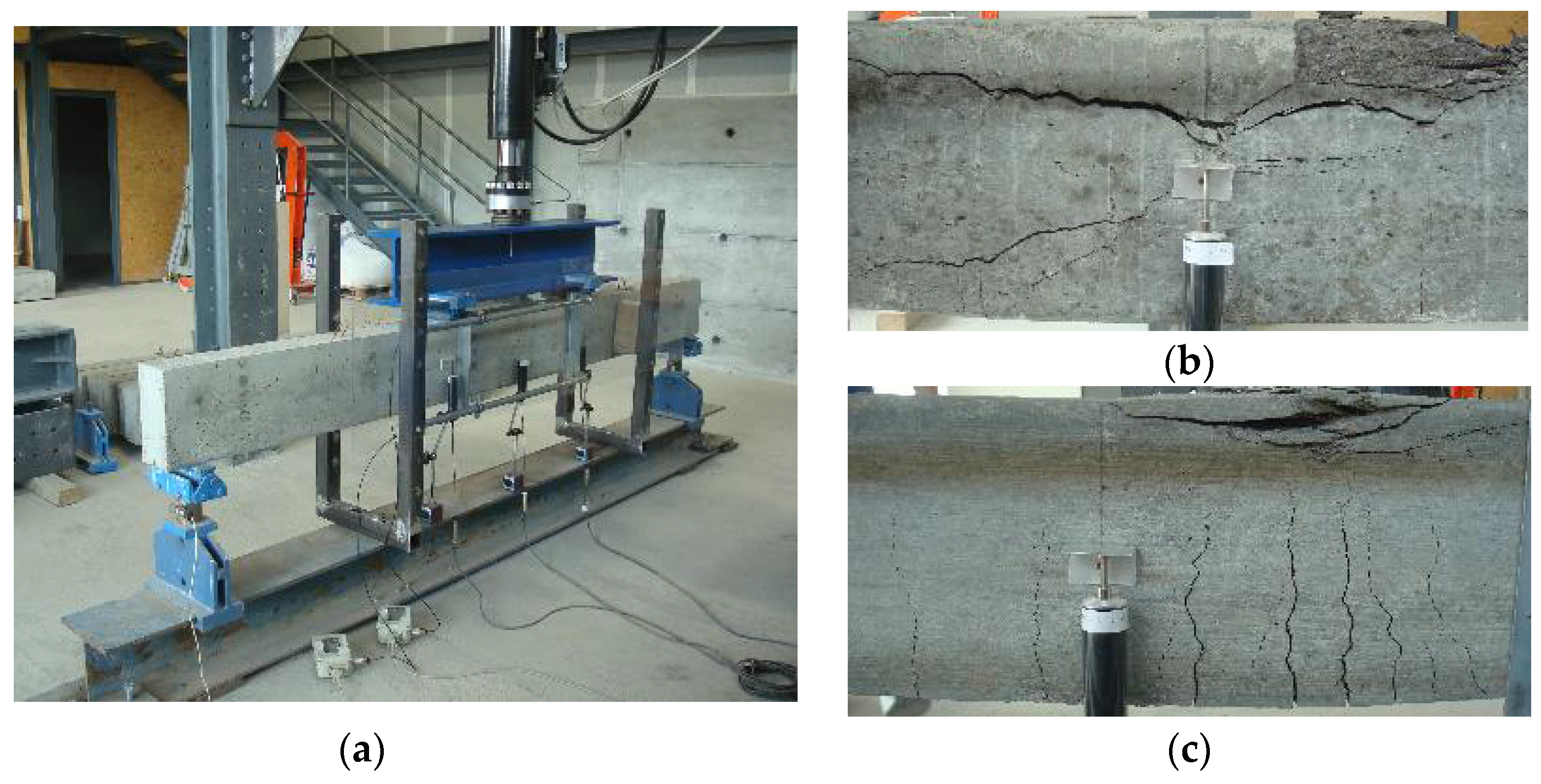
The principal aim of this study was the analysis of the load capacity, stiffness, and ductility of LWAC beams submitted to pure bending [
16]. For this purpose, three sets of tests were carried out, one for each considered parameter: tensile reinforcement ratio, transversal reinforcement ratio, and concrete’s compressive strength. Thirteen beams with 3000 mm length, 120 mm width, and 270 mm height were tested. The load was applied through a hydraulic servo-actuator using displacement control and a constant speed of 0.01 mm/s (
Figure 1). During the tests, measurements were made to characterise the beams’ behaviour. More specifically, support reactions and displacements at critical points were recorded.
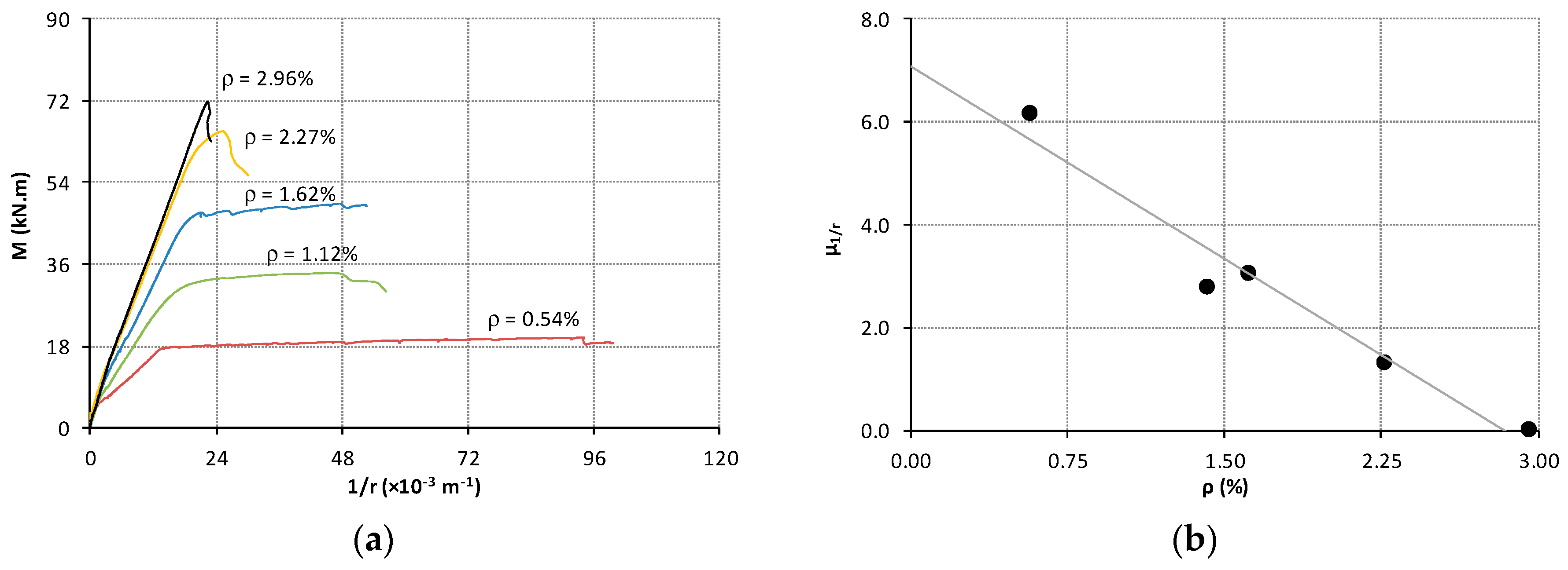
A summary of the main conclusions is as follows: (i) When concrete strength remains constant, the deformation capacity of LWAC beams decreases significantly with the increase of the tensile reinforcement ratio; (ii) The vertical displacements and curvatures in critical sections increase with the increase in concrete strength, and this effect is more evident in beams with lower tensile reinforcement ratios; (iii) The ductility index, in this case the curvature ductility index, defined as the ratio between the curvature corresponding to the ultimate moment and the curvature corresponding to the yielding moment, showed that the plastic deformations are mainly influenced by the tensile reinforcement ratio (
Figure 2); (iv) Beams without transversal confinement in the central region of the beam presented a more fragile failure comparatively to beams with transversal confinement; (v) Higher transversal reinforcement ratios also led to an increase of the load capacity.
2.2. Punching Capacity of Thin LWAC Slabs
Combining reduced weight and good mechanical performance, LWAC is an efficient solution for flat slabs. Therefore, another experimental study was carried out to analyse the influence of the punching capacity in thin LWAC slabs [
17]. Six slabs of 1000 × 1000 × 100 mm
3 were produced without shear reinforcement using three different types of LWAC with the same density, 1900 kg/m
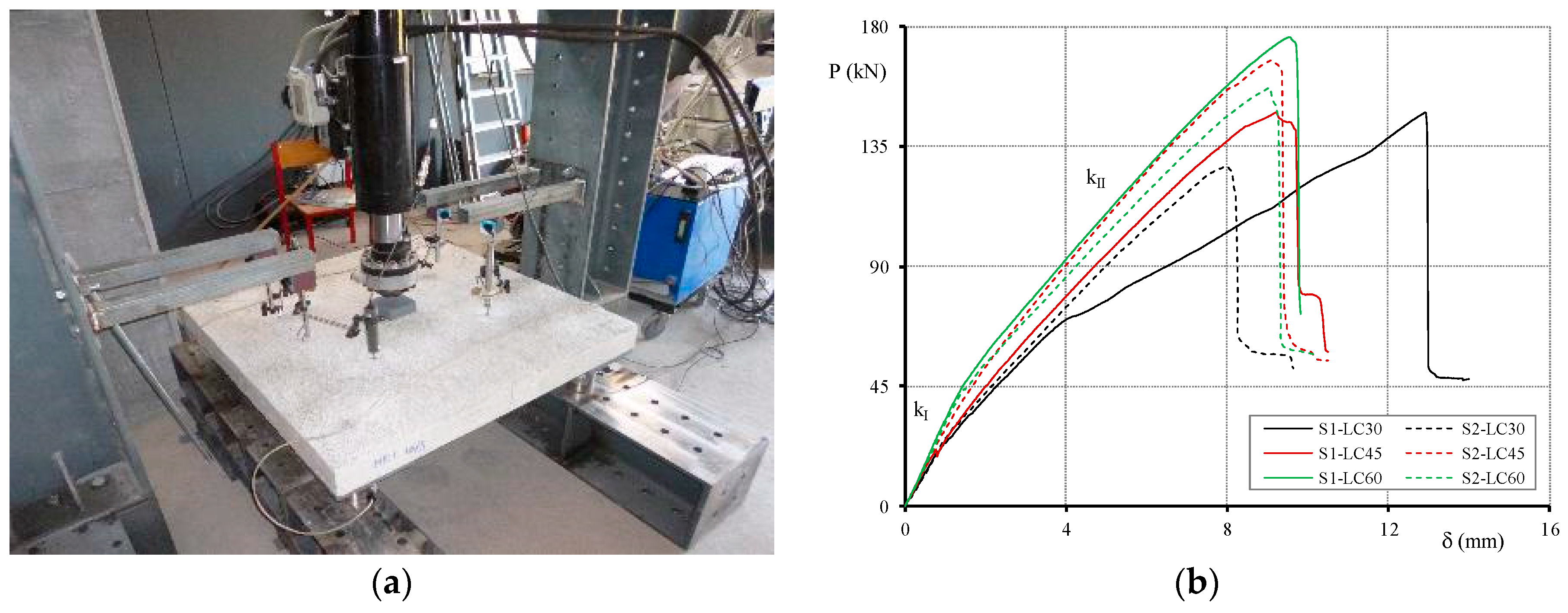
3, and with equal longitudinal reinforcement ratio, namely Ø12 rebars spaced 100 mm in both directions. The average compressive strength was 29, 42, and 54 MPa. Two equal slabs for each type of concrete were produced. The steel amount was defined in order to avoid a premature bending failure. Hot-rolled ribbed rebars S500NR-SD were adopted, presenting an average yield strength of 545 MPa. The slabs were supported at the four corners on semi-spherical supports, allowing the slabs free rotation at these points, and a concentrated force was applied at the centre of the slabs (
Figure 3a). The loaded area was 120 × 120 mm
2, and the force was applied using a hydraulic servo-actuator with displacement control at a rate of 0.02 mm/s. During the tests, the load and the support reactions were measured using load cells, and the deformation at critical points was measured with linear variable differential transformers (LVDTs) with a frequency of one record per second. The tests stopped when shear-punching failure occurred, identified by a significant drop in the strength capacity.
Based on the experimental results, cracking and maximum loads, displacements, rotations, stiffness, failure modes, and cracking patterns were analysed. The experimental results also allowed assessing the applicability of EC 2,
fib MC 2010, and ACI 318 to thin LWAC slabs [
18,
19,
20]. The main conclusions of this study are: (i) the size and type of aggregate are essential to predict the punching capacity of LWAC slabs without specific reinforcement; (ii) the concrete strength has a direct influence on the shear punching strength, increasing from 127.6 to 175.7 kN, when f
lcm increases from 29 to 54 MPa (
Figure 3b); (iii) the predictions of punching strength using both ACI 318 and MC 2010 for LWAC thin slabs are safe; and (iv) the measured angles of the failure punching ‘cone’ are very similar to the value recommended by EC 2.
2.3. Exterior Beam-To-Column Joints of LWAC
This study aimed at evaluating the influence of rebar detailing, LWAC strength, and reinforcement ratio on the joints’ behaviour. The beam-to-column joints play a key role in the behaviour of reinforced concrete frames under monotonic and dynamic actions, and if not properly computed and detailed, their strength capacity can be lower than expected. To properly execute the joints can also be complex, especially when small cross sections with a significant number of rebars are adopted because this hinders concrete casting. The outer beam-to-column joints are more vulnerable than the inner ones due to uneven geometry and unbalanced structural behaviour accompanied by less effective confinement conditions [
21,
22,
23,
24,
25,
26,
27].
Considering the lack of studies considering these conditions, an experimental study [
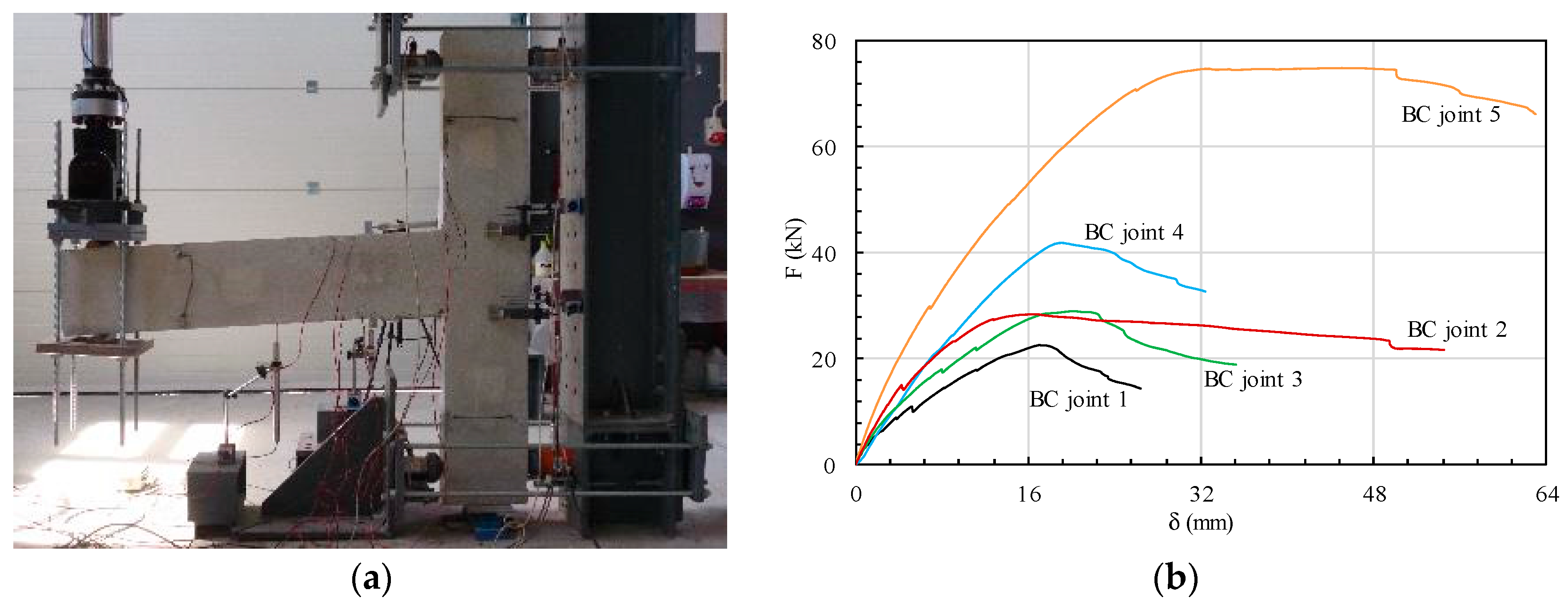
28] focused on the behaviour of exterior beam-to-column joints made with LWAC and under monotonic loads was conducted. Five specimens were produced combining two different reinforcement ratios and LWACs with two different strengths. The concrete adopted had a compressive strength of 35 and 55 MPa, and the tensile reinforcement ratio was 1.12 and 2.96%. Four specimens had the same cross-section, 120 × 270 mm
2, equal for columns and beams, and in the remaining, it was changed to 220 × 270 mm
2 to allow a better anchorage of the longitudinal rebars of the beam. The lengths of column and beam were 1500 and 1200 mm, respectively (
Figure 4a).
The experimental results demonstrated that adequate detailing of the reinforcement in the beam-to-column joint considerably reduces cracking and increases the load capacity. More specifically, the longitudinal reinforcement of the beam should be anchored at the outer face of the column with a hook, and a high volume of concrete in compression is required when high reinforcement ratios are used. These specifications are essential for the internal balance of forces between the beam and the column. This study also showed that the column’s transversal reinforcement within the node is fundamental to transfer horizontal forces from the outer to the inner face, avoiding concrete spalling in the outer region, and ensuring a correct behaviour of the joint. The increase of LWAC strength did not have a significant impact in the joints’ behaviour for low reinforcement ratios, whereas for specimens with higher reinforcement ratios, the maximum load increased, the tensile reinforcement was better mobilized, and more ductile failure was observed (
Figure 4b).
3. GFRP Reinforcing Bars
Reinforced concrete structures present the risk of steel rebars’ corrosion. The required protection depends on the environmental exposure and on the design service life of the structure. Typically, the quality and the thickness of the concrete cover are specified based on the latter parameters. There are, however, other solutions to eliminate, or at least to minimize, the problem of steel corrosion, such as the adoption of stainless steel or even non-metallic reinforcement, as for instance glass fibre–reinforced polymer (GFRP) rebars. These are suitable for very aggressive environments and/or when high durability is required.
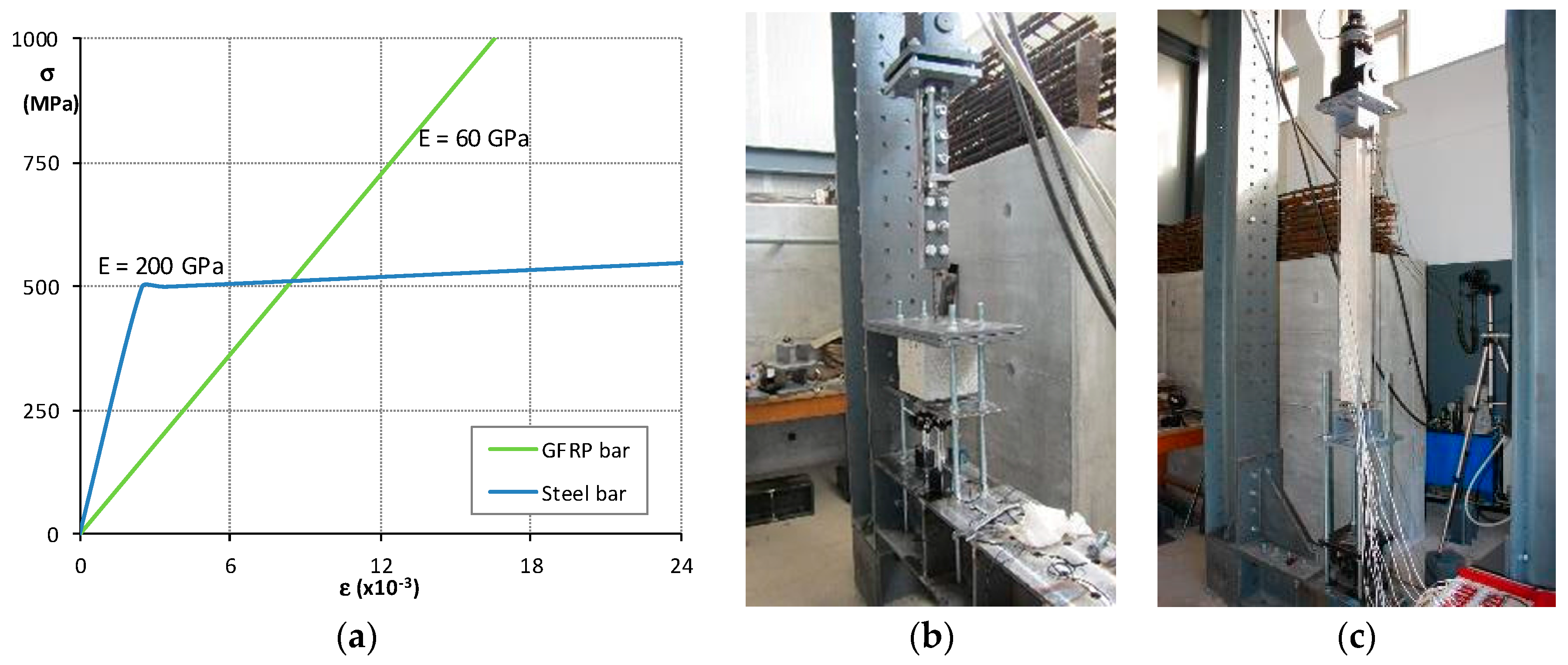
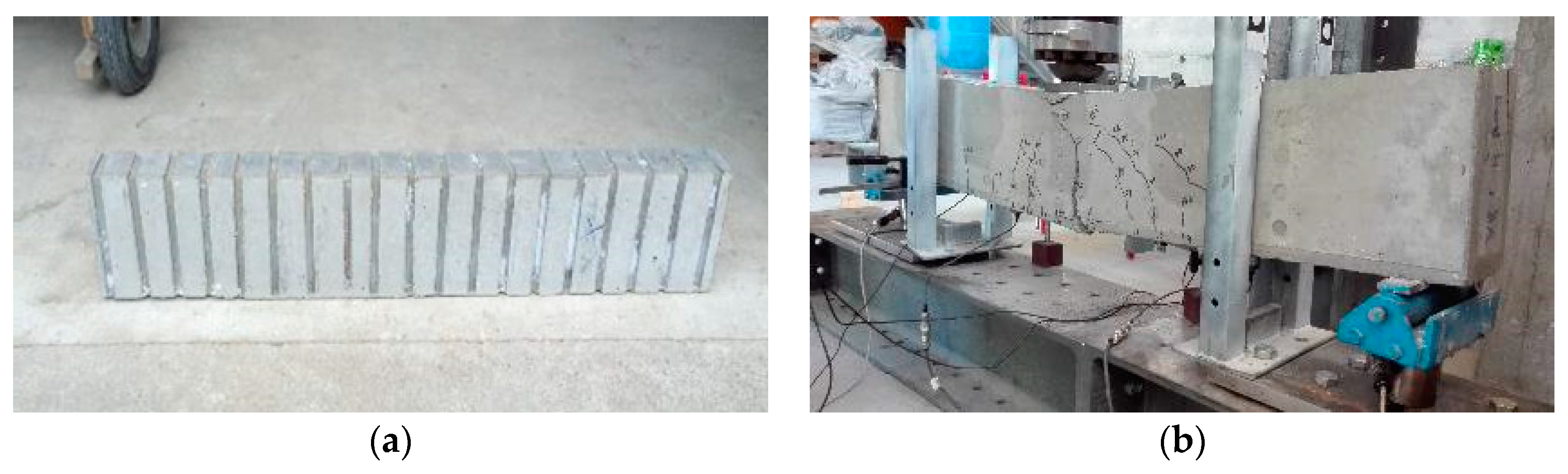
The GFRP rebars also have the advantage of presenting high tensile strength and, in addition, of being easy to cut and carry. Their disadvantages are that they cannot be bent at the construction site and they exhibit low strength to shear and compressive forces. Ribs of GFRP rebars are also different from those of steel rebars, and the Young’s modulus is significantly lower, which undoubtedly affects the structure’s behaviour [
29,
30] (
Figure 5a). To analyse these differences, an experimental study was carried out using both steel and GFRP rebars [
31]: (i) 36 pull-out tests were produced, 18 with steel rebars and 18 with GFRP rebars, combining different rebar diameters and concrete strengths (
Figure 5b); (ii) 12 1200 × 100 × 100 mm
3 ties were produced, six with steel rebars and six with GFRP rebars. The ties were reinforced with one rebar applied at the centre of the cross section (
Figure 5c).
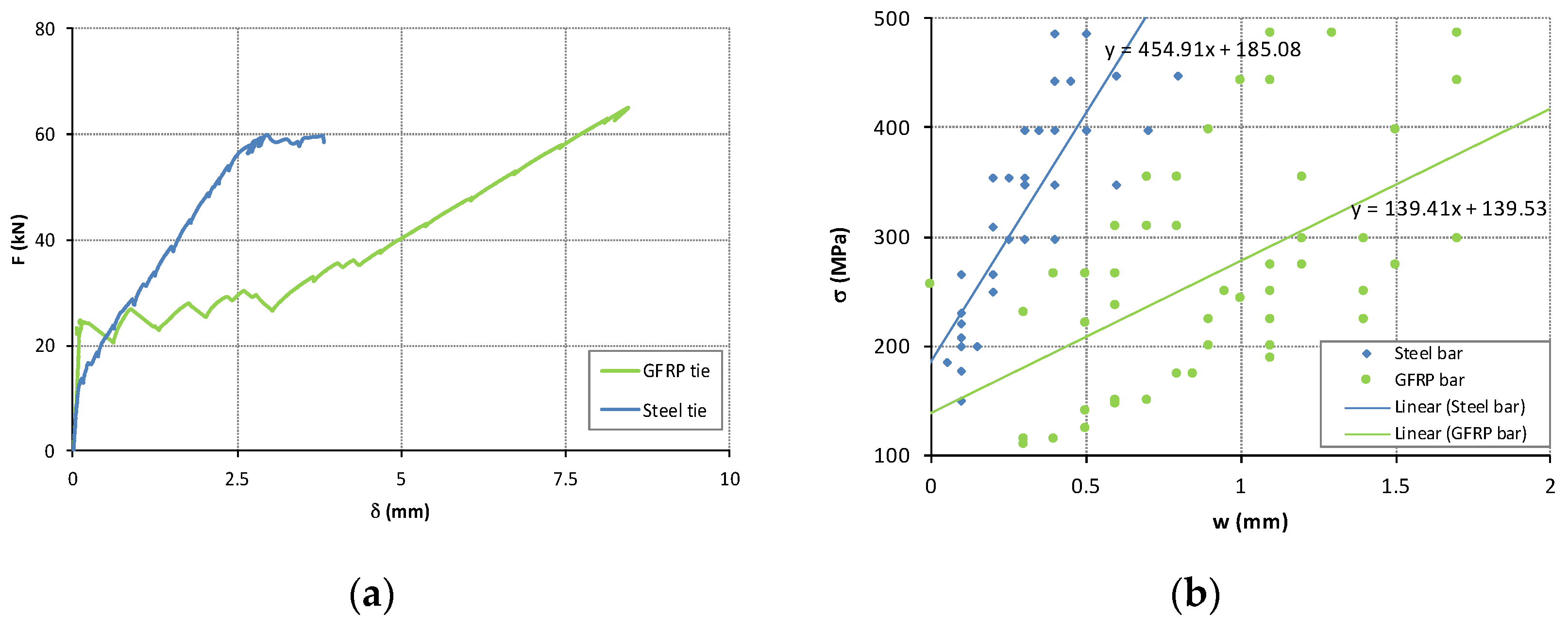
Considering the results of pull-out tests, the two types of rebars (steel and GFRP) have a similar bond strength, but the anchorage length of GFRP rebars must be double, considering its maximum strength. The ties reinforced with GFRP present deformations higher than those recorded in identic ties reinforced with steel rebars during state II, i.e., between the development of the first crack and the instant steel rebars start yielding. The stiffness K
II is greatly affected by the Young’s modulus of the rebars’ material and it is slightly affected by the variation of the concrete’s strength (
Figure 6a). For the same level of stress, the cracks’ width is inversely proportional to the Young’s modulus of the rebars’ material. In ties with GFRP rebars, cracks’ width is, on average, 3.3 times higher than that of ties with steel rebars (
Figure 6b).
4. Structures Made with Nanoconcrete
Over the last few years, several studies on concrete mix design, considering different additions of nanoparticles, have been carried out intensively. The rational use of nanoparticles, i.e., particles with diameters varying between 0.1 and 100 nm, with a high specific surface-volume relation [
32,
33], and with high reactivity during the cement’s hydration process, is mainly used to make the cementitious matrix more compact, thus improving the mechanical properties and durability of concrete [
34,
35]. The nanoparticles of silica (SiO
2), usually named nano-SiO
2, are one of the most used in this field because they have shown good results in increasing the matrix density. Other types of nanoparticles that have also been studied as additions to concrete mixes are nano-TiO
2, nano-ZnO
2, nano-Fe
2O
3 and nano-Al
2O
3 [
36,
37].
Studies on the addition of nanoparticles to concrete mixtures are focused mainly on the material behaviour and secondarily on the structural behaviour of concrete members incorporating nanoparticles. Most recent experimental studies conducted by the authors aimed at understanding the effect of the addition of nanoparticles on the steel-to-concrete bond [
38,
39] and on both the shear strength and the bending strength of RC beams [
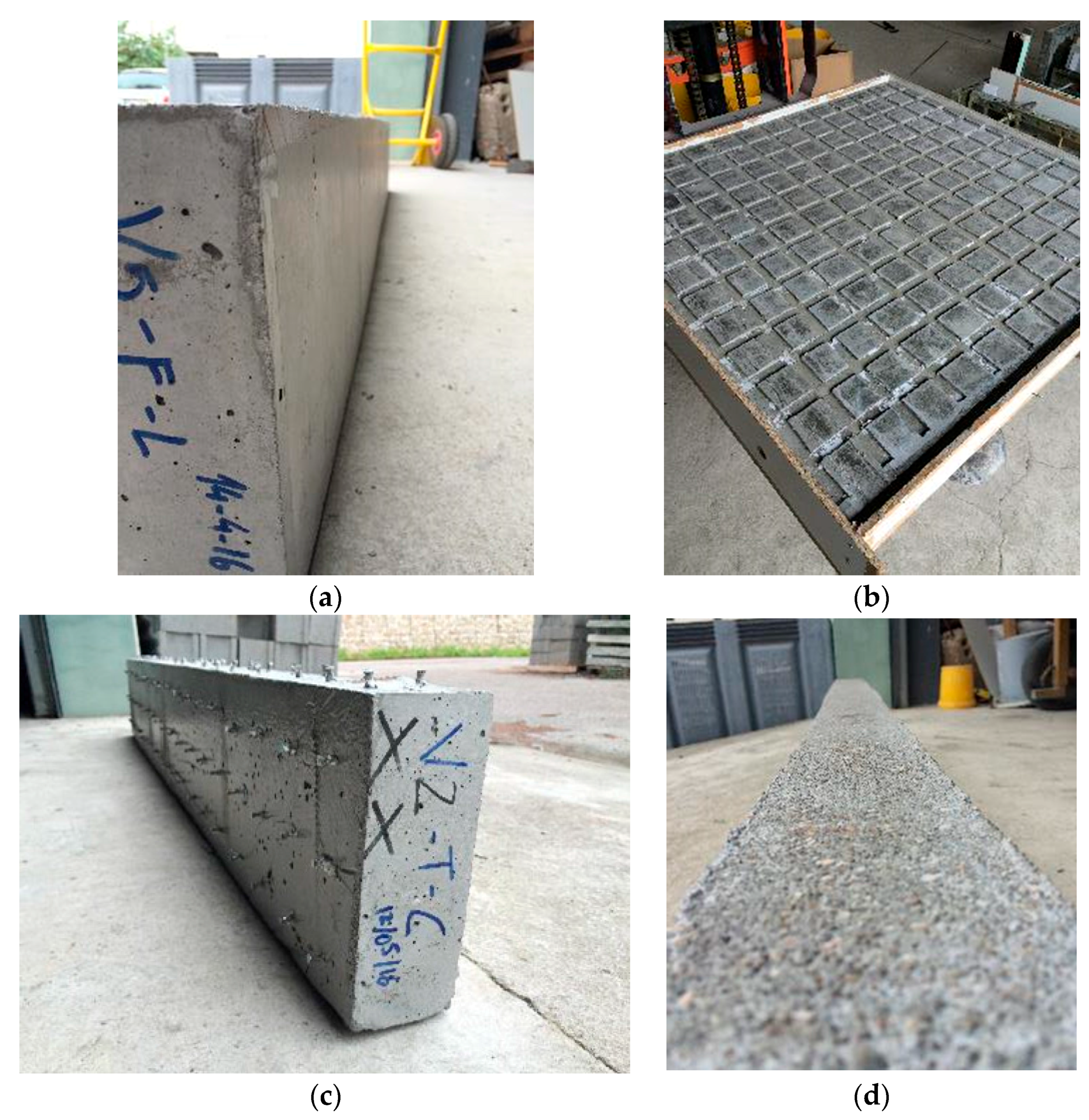
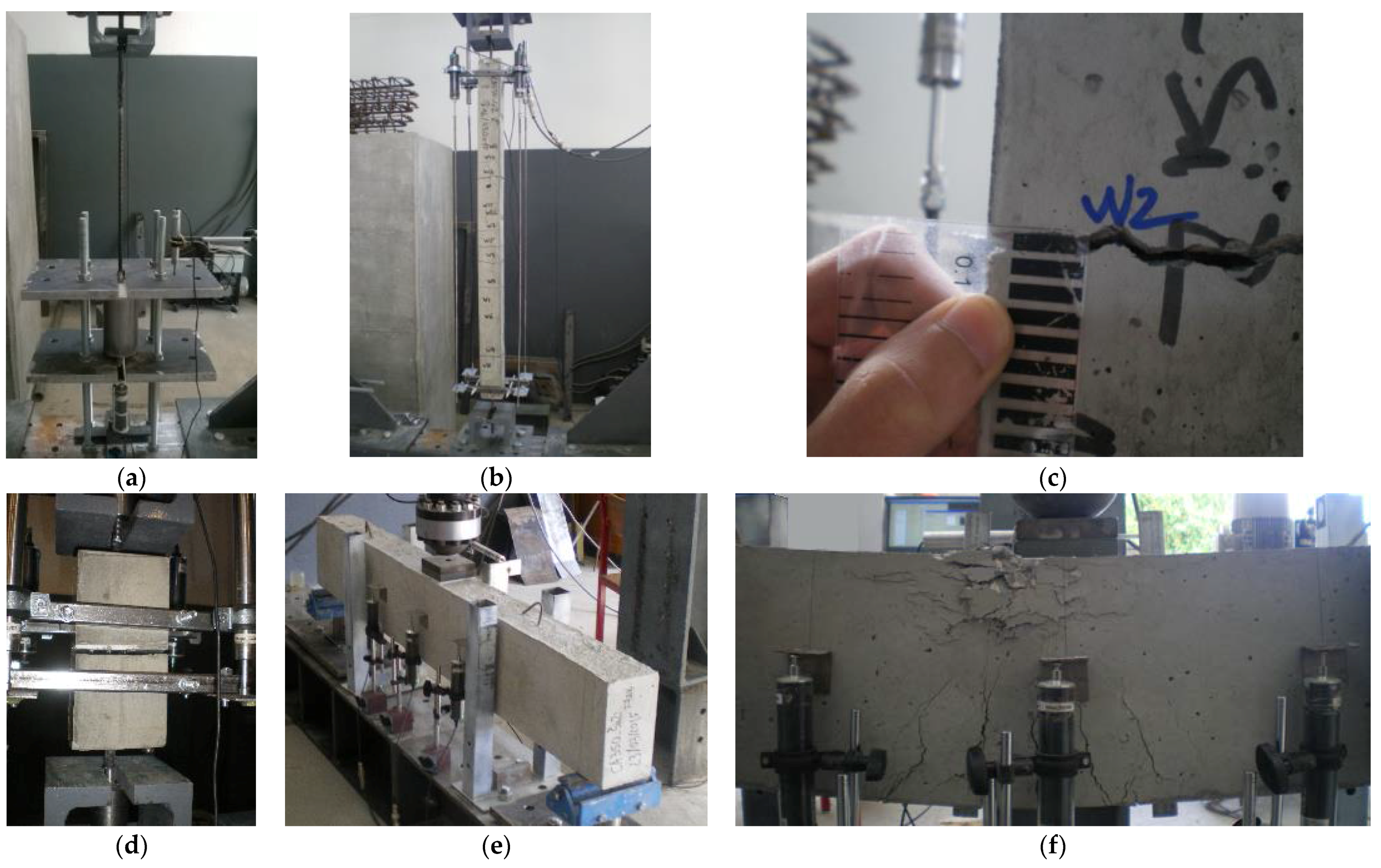
40]. To characterize the steel-to-concrete bond stress, 32 pull-out tests (
Figure 7a) and 16 tensile tests were performed. The latter were conducted on reinforced concrete ties, and the goal was to analyse the cracks’ width (
Figure 7b,c). In these tests, plain and ribbed rebars, as well as eight different types of concrete mixtures, were used [
38]. The effect of adding nanoparticles on steel fibres-to-paste bond was also analysed using a modified pull-out test to monitor the fibre’s slip versus the applied load (
Figure 7d) [
39]. The strength capacity of beams with nanoparticles was evaluated by testing 16 reinforced concrete beams (
Figure 7e,f) [
40].
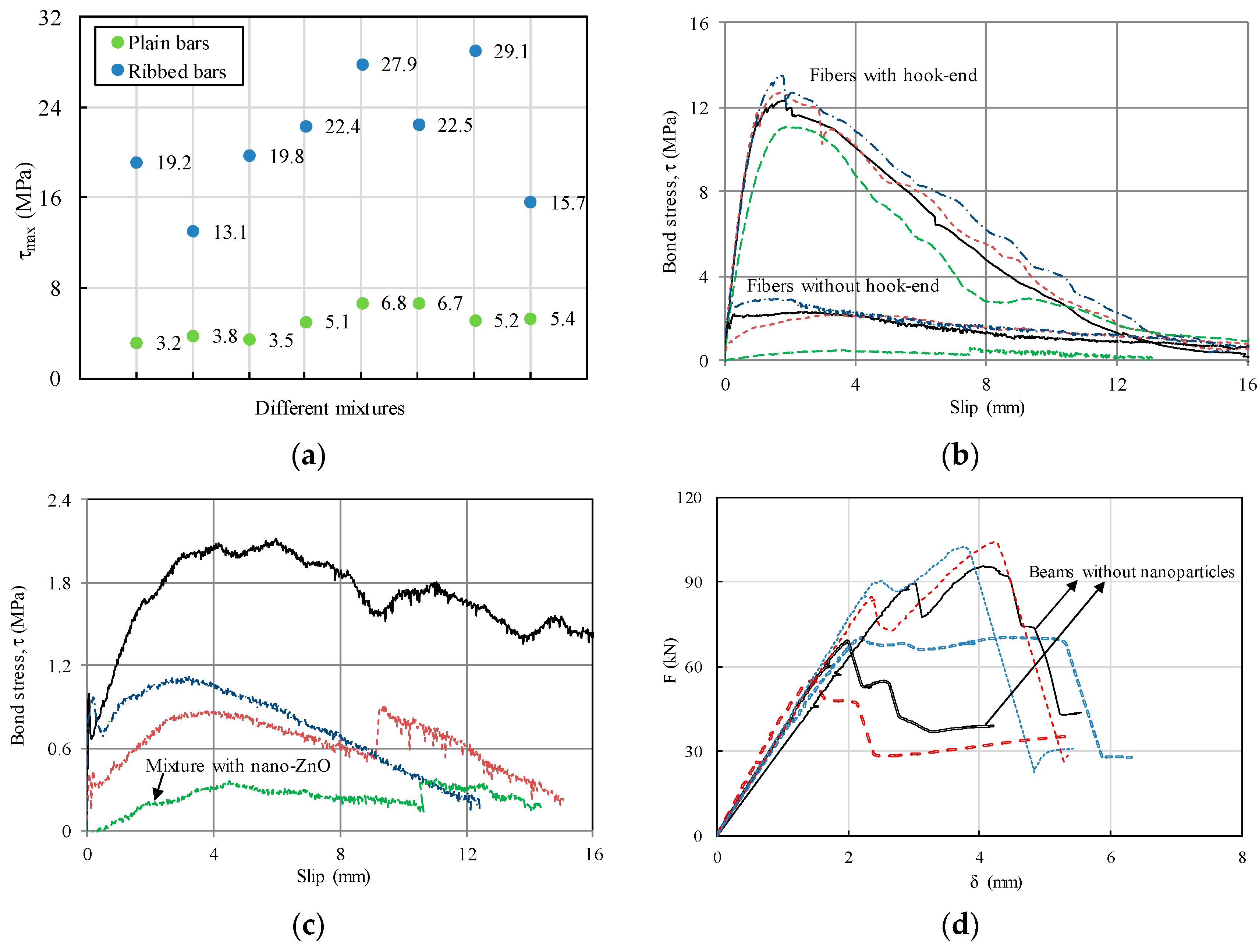
Based in these studies, the following conclusions were drawn: (i) Adding nanoparticles to the concrete mixture influences mostly the adhesion component, which is particularly relevant when plain rebars are used. (ii) Regarding the cracks’ width, the effect of the rebars’ ribs is predominant compared to the addition of nanoparticles, thus leading to a higher increase in bonding (
Figure 8a). (iii) The mechanical component of bond provided by the hook at the end of the fibres is, as expected, much higher than the adhesion and friction components, and it exceeds considerably the improvement reached with the nanoparticles addition. (iv) In spite of the latter, the nanoparticles addition leads to an increase of the binding paste strength and thus to an increase of the bond strength (
Figure 8b). (v) The nano-ZnO addition has a negative effect on the bond strength, probably due to a chemical reaction with the fibres’ coating (
Figure 8c). (vi) Finally, the effect of nanoparticles in the beams’ behaviour is influenced by the dosage of the cement adopted in the mixture. For beams produced with higher dosages of cement, the addition of nano-SiO
2 or nano-Al
2O
3 leads to an increase in the shear strength. However, they have almost no influence in the bending strength (
Figure 8d).
5. Structures with Ultra-High Durability Concrete Cover
After Lafarge patented Ductal and released it to the market [
41], several researchers all over the world developed different mixtures for ultra-high-performance concrete (UHPC), which is also called ultra high–performance fibre-reinforced concrete (UHPFRC). Most of these studies were focused on the material properties, and only few addressed the behaviour of structural UHPC members. In this latter group of studies is included the work by Bruwhiler et al., developed at EPFL, which uses UHPC to improve the performance of both existing and new concrete structures [
42,
43].
The research developed at CERIS, although also focused in structural UHPC, has a somehow different goal and focus. The goal is to enhance durability, which is why the authors often refer to ultra-high durability concrete (UHDC) instead of UHPC, and to reduce the carbon footprint of the composite UHPC-concrete member. The main characteristic of this UHPC is an ultra-compact matrix with reduced porosity, giving rise to an excellent performance in terms of durability and mechanical properties. The compressive strength can be higher than 150 MPa, and tests performed to assess the water absorption, corrosion rate of steel, and the porosity proved that UHPC is particularly adequate for reinforced concrete structures located in very aggressive environments [
4,
44]. The composition of these UHPC usually contains fibres, nanoparticles, fly ash, and a large amount of cement, between 900 and 1100 kg/m
3, which is substantial higher than the cement dosage in normal concrete [
45]. Thus, aiming at reducing the environmental impact associated with the production of these UHPC, it was developed at CERIS the ‘Eco-UHPC’ concept [
3,
45].
Although UHPC has been adopted in different types of reinforced concrete structures, authors have focused on a specific application: the production of a ‘super skin’ that enhances the durability of current concrete members. This concept was developed in the scope of a research project called ‘Intelligent Super Skin—Enhanced Durability for Concrete Members’ funded in 2004 by the Portuguese Science and Technology Foundation. In this project, several UHDC mixtures were developed and characterized. Also, for the first time, the concern with eco-efficiency was included in the UHDC mixture design [
45]. Presently, a vast experimental campaign is in progress, aiming at analysing the best way to apply this innovative ‘eco-super skin’, considering different types of concrete for the bulk (LWAC and LBC, besides current concrete) and different types of surface conditions for the interface between the cover and the bulk (
Figure 9). The characterization of the bond between the UHDC cover and the concrete bulk, considering all the variables above-mentioned, is also a goal that differentiates the authors’ research from other studies.
The tests were performed in beams and slabs to analyse the contribution of the ultra-high durability concrete cover in the structural behaviour, namely in terms of strength, stiffness, cracking pattern, deformation, and ductility (
Figure 10). Some tests have already been performed, but results are not yet analysed.
This solution is interesting for enhancing the durability without being required high amounts of cement, since UHDC is only considered in the cover, thus resulting in a more economic and sustainable solution, and it has the additional advantage of being applicable to both new and existing structures, i.e., it can also be adopted in rehabilitation and strengthening interventions.
6. Final Considerations
This overview of some recent studies conducted by the authors shows that there is a huge potential for innovation in the structural concrete area. Currently, the paradigm is to improve the performance considering, simultaneously, strength, durability, eco-efficiency, and cost, from a life-cycle perspective. The experimental studies conducted by the authors in recent years, herein presented, are contributions in this domain and the following main conclusions drawn are synthesized next.
Regarding LWAC, it can be stated that it is possible to design LWAC structures with the prescribed strength and ductility, requiring special care with both transversal and longitudinal reinforcement ratios. LWAC structures can be a very competitive solution with the advantage of significantly lowering the structures’ dead weight.
In aggressive environments where the risk of steel corrosion is high, non-metallic rebars, like GFRP rebars, are an interesting alternative to stainless steel. Nevertheless, these rebars require double anchorage length compared to current steel rebars, and the stiffness of the structure in state II is highly affected by the low Young’s modulus of this reinforcing material. In addition, when GFRP rebars are adopted, the expected cracks’ width is, on average, 3.3 times higher compared with the reference situation of using steel rebars. Results showed that the cracks’ width is inversely proportional to the Young’s modulus of the adopted reinforcing material.
The experimental studies performed to analyse the effect of using nanoparticles additions in concrete mixtures showed that the cementitious matrix is more compact when nanoparticles are added, thus also improving both the mechanical properties and the durability. It was also demonstrated that, regarding steel fibres reinforced concrete, the hook at the end of the fibres has a much higher effect than the improvement reached with the nanoparticles addition. Moreover, it was found that nano-ZnO affects negatively the fibre-to-matrix bond strength, probably due to a chemical reaction with the fibres’ coating. Regarding the effect of nanoparticles addition on beams behaviour, it was concluded that the shear strength increases with the nanoparticles addition and the strength capacity increases slightly, whereas the effect on the bending strength is not significant.
Finally, the new concept, named by the authors as ‘super skin’, proved to be a promising approach to enhance the durability of concrete structures. Using a normal concrete in the core and an UHDC only in the cover, the result is a high-performance solution, combining all the current concerns previously identified. In fact, it proved to be cost effective, to improve durability, to increase strength, and to be eco-efficient according to a life-cycle perspective. Studies on this subject are still in progress and will be published soon.


