1. Introduction
Among the most critical phenomena affecting the stability and durability of dams are water seepage under the foundations. These underground flows are not only a source of significant water losses, but they also generate uplift pressures that reduce the structure’s stability. In the most unfavorable cases, they can cause internal erosion, known as “piping,” which can lead to sudden failure. Controlling these flows and their effects is therefore an absolute priority in dam engineering.
As early as the beginning of the 20th century, empirical methods were developed to address these risks. The creep theories of Bligh [
1] and Lane [
2] were the first approaches aimed at estimating hydraulic gradients and uplift pressures beneath hydraulic structures. Although groundbreaking for their time, these methods had significant limitations, particularly their inability to account for the geometric complexity of the layouts and the heterogeneity of foundation soils.
Mathematical and numerical advances in the mid-20th century led to the development of more sophisticated models. The work of Khosla et al. [
3], based on the theory of complex functions, provided a rigorous analytical alternative for calculating flows under foundation slabs. However, the computational complexity limited their practical applicability, leading to the creation of design charts that are still used today for preliminary designs.
Subsequently, the emergence and democratization of numerical computation tools revolutionized the study of flow in porous media. Researchers such as Malhotra [
3] and later Chawla and Kumar [
4] progressively integrated more realistic boundary conditions, such as foundations of finite depth, a situation far more common in practice than the assumed semi-infinite case.
The analysis and control of seepage under hydraulic structures have advanced considerably with the development of numerical tools. The advent of methods such as the Finite Element Method (FEM) and the Boundary Element Method (BEM) has enabled refined modeling, adaptable to the complexity of geometries and hydraulic conditions encountered in the field. Today, specialized software, such as SEEP/W, PLAXIS, ANSYS, and Geo-Studio, is widely used to simulate seepage, evaluate the effectiveness of control measures, and optimize designs.
Many studies have focused on analyzing the influence of key parameters on hydraulic behavior. The pioneering research of Najjar and Naouss [
5], using FEM, paved the way for systematic analysis of cutoff walls in non-homogeneous soils. Later, the work of Neshaei et al. [
6], using BEM, showed that the inclusion of a central cutoff wall had no significant impact, in contrast to walls positioned at the extremities.
The optimization of cutoff walls has been the subject of extensive research. Mansuri et al. [
7] and Shayan et al. [
8] confirmed, using SEEP/W (a part of GEOSTUDIO 2007 software package), that placing the wall upstream minimizes uplift pressures, while a downstream location is more effective in reducing the exit gradient. These findings were corroborated by Alrowais et al. [
9], who established that the most effective position for reducing uplift forces under static conditions is at the upstream heel of the dam. More recently, Sartipi et al. [
10] conducted a systematic analysis of the effects of wall location, number, and depth, while Praveenkumar et al. [
11] experimentally quantified the impact of wall inclination. The efficiency of double walls has been investigated by Asaad M. Armanuos et al. [
12] and Salmasi et al. [
13] using FEM. In parallel, Salmasi and Nouri [
14] demonstrated the effectiveness of upstream semi-impervious blankets in reducing uplift pressures and seepage.
Drainage systems constitute an essential complementary solution. Their performance has been thoroughly analyzed by authors such as Salmasi et al. [
15] and Nourani et al. [
16]. The work of Ali Taheri Aghdam [
17] on pipe drains showed that upstream placement minimizes uplift pressures, while downstream drains are optimal for controlling the exit gradient.
The synergistic combination of cutoff walls and drainage systems has emerged as the most robust solution. The work of Khalili Shayan and Amiri-Tokaldany [
18] and Mahtabi and Taran [
19] demonstrated that such an association can effectively reduce the hydraulic gradient, a conclusion further confirmed by recent case studies, such as that of Charrak et al. [
20] on the Algerian Sidi Abdelli dam. Expanding on this perspective, Parsaie [
21] identified the optimal configuration combining a drainage well with a cutoff wall.
Given the multiplicity of parameters, modern optimization methods—sometimes involving genetic algorithms [
22]—now make it possible to automatically determine the optimal configurations for given conditions. However, these advanced approaches rely on a thorough understanding and prior quantification of the influence of each parameter, typically obtained through systematic parametric analyses.
A comprehensive review of the scientific and technical literature has identified the position, depth, and inclination of the cutoff wall as fundamental geometric parameters in the design of seepage control systems beneath dams. The position and depth are widely recognized as key factors in reducing seepage discharge and uplift pressures [
23,
24]. Inclination, a less explored parameter, has recently shown promising potential for improving the hydraulic performance of cutoff walls [
25]. Based on this literature review, the quantitative evaluation of these three geometric variables—despite the construction constraints associated with inclination—makes it possible to assess their potential benefits and better guide design decisions.
Within this context, the present study aims to contribute to the optimization of seepage control systems beneath rigid dams. It focuses specifically on structures founded on permeable alluvial formations, where water flow through the foundation is unavoidable, and the control of uplift pressures through a cutoff wall is a central design concern. In such loose foundations (alluvium, sands, gravels, and clays), the height of rigid concrete or masonry dams is generally limited to approximately fifteen meters.
Using numerical modeling performed with the Plaxis 2D software, whose capability to accurately simulate flow in porous media has been previously demonstrated, a systematic parametric analysis is conducted to evaluate the combined influence of the position, depth, and inclination of a cutoff wall on the hydraulic performance of the structure. Particular attention is given to the validation of numerical results through comparison with reference analytical solutions, thereby ensuring the robustness and reliability of the simulations. The findings of this study are intended to provide practical guidance for the design of safer, more durable, and more efficient seepage control systems.
2. Methodology
2.1. Software and Numerical Model
The study was carried out using Plaxis 2D (2024 version), a software tool specializing in geotechnical engineering. It was used to simulate water seepage beneath a concrete dam, founded on a homogeneous and isotropic soil. Both hydraulic and mechanical boundary conditions were defined in accordance with the standards and recommendations for the software’s use.
2.2. Model Geometry and Study Parameters
The simplified model considers a dam resting directly on its foundation, without a detailed representation of anchorage. This assumption is intended to isolate the influence of the geometric parameters of the cutoff wall while limiting the number of variables involved in the analysis.
The preliminary geometric design is based on empirical guidelines commonly used in dam engineering. According to these recommendations, the base width of a gravity dam typically ranges between 0.8 and 1.2 times the height of the structure [
26]. In the present study, the dam geometry is defined by its height
and base width
, with a ratio
. This value lies at the midpoint of the recommended range, and therefore, represents a realistic and representative geometry for a concrete gravity dam [
26].
From a hydraulic perspective, seepage parameters beneath the structure depend primarily on the base width and the hydraulic head , while being only marginally influenced by the shape of the upstream and downstream faces above the base. By fixing the ratio to a constant value of 1.2, the analysis can, therefore, focus on the influence of the geometric parameters of the cutoff wall—namely its position , depth , and inclination —on the hydraulic performance of the structure. The trends obtained remain qualitatively valid for other values of the ratio.
The dam geometry, along with the parameters used in the calculations, was defined based on common practices in dam engineering. To facilitate numerical analysis, certain assumptions and simplifications were introduced while maintaining a sufficient level of physical representativeness to meet the objectives of the study.
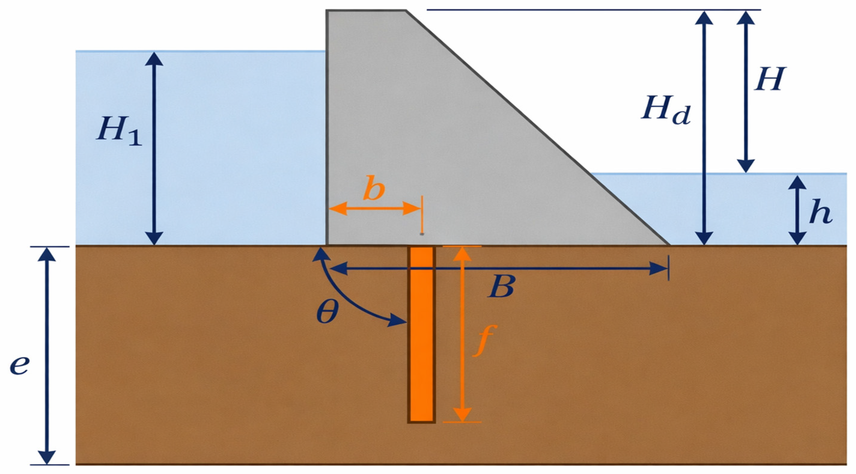
Figure 1 illustrates the adopted model geometry, including its main dimensions and parameters.
e: Thickness of the permeable foundation layer (m), resting on an impermeable substratum;
: Base width of the dam (m);
: Horizontal distance between the upstream toe of the dam and the cutoff wall (m);
: Height of the dam (m);
: Crest width of the dam (m);
: Upstream water head (m);
: Downstream water head (m);
: Total hydraulic head difference between upstream and downstream ();
: Penetration depth (embedment length) of the cutoff wall (m);
: Inclination angle of the cutoff wall, measured with respect to the horizontal from upstream to downstream, with ranging from 0° to 165°;
: Acceleration due to gravity (m/s2);
: Permeability of the foundation soil (m/s);
: Unit weight of water (N/m3).
The inclination angle of the cutoff wall is defined with respect to the base of the dam. Under this convention, corresponds to a horizontal wall. When the cutoff wall is located at the upstream side (), this configuration is equivalent to an impermeable upstream blanket. However, for other positions of the wall (), an angle of would correspond to a horizontal wall coinciding with the dam base, which is not physically meaningful within the framework of this study. For this reason, this case was not considered in the analysis.
All geometric parameters were kept constant, except for the three variables under investigation (position, depth, and inclination), in order to isolate their influence on the hydraulic performance.
2.3. Material Assumptions
In this modeling approach, the foundation soil is assumed to be homogeneous and isotropic. Under these conditions, the hydraulic results (uplift pressures and hydraulic gradients) are independent of the exact permeability values, in accordance with Laplace’s equation. This assumption allows for a general assessment of the influence of the geometric parameters of cutoff walls. This assumption results in identical permeability values in all directions:
The concrete dam body, on the other hand, is considered perfectly impermeable.
2.4. Numerical Experimental Plan
The parametric study consists of simulating the dam’s behavior by systematically varying the key parameters of the cutoff wall. The tested values are as follows:
Relative embedment depth of the cutoff wall (): 0, 1/6, 1/3, 2/3, and 5/6;
Relative position of the cutoff wall (): 0, 0.25, 0.5, 0.75, and 1;
Inclination angle of the cutoff wall (): 0°, 15°, 30°, 45°, 60°, 75°, 90°, 105°, 120°, 135°, 150°, and 165°;
Where
: Ratio of the cutoff wall length to the foundation thickness;
: Ratio of the distance of the cutoff wall from the upstream heel to the width of the dam base.
2.5. Mesh and Hydraulic Boundary Conditions
A mesh composed of 15-node elements was generated to discretize the study domain. To achieve better accuracy of the results, local mesh refinement was applied in three critical zones:
The hydraulic boundary conditions defined for modeling are as follows:
A constant hydraulic head, corresponding to the water height 1 is applied to the upstream boundary.
A constant hydraulic head, corresponding to the water height is applied to the downstream boundary.
The lateral boundaries and the base of the model are considered impermeable.
3. Results and Discussion
Although steady-state seepage is governed by well-established equations, the absence of simple analytical solutions for geometries involving multiple variable parameters (such as the position, depth, and inclination of a cutoff wall) justifies the use of a systematic parametric study based on numerical modeling. Such an approach not only enables precise quantification of the influence of each parameter but also allows the identification of their interactions and the determination of optimal configurations that satisfy multiple, and sometimes conflicting, criteria.
To verify the validity of the adopted model, a comparison of seepage discharge was carried out using the chart by Polubarinova-Kochina [
27].
The tested configuration corresponds to a vertical cutoff wall (
= 90°) located at the center of the foundation (
= 0.5), with a relative embedment ratio f/e of 0.5 (
Table 1). For these parameters, the calculation provides a relative seepage discharge
of 0.3972. This value is in excellent agreement with the reference chart reading of 0.4 (
Figure 2), thereby confirming the relevance of the chosen model.
3.1. Analysis of the Influence of Cutoff Wall Position and Depth on Seepage Discharge
Without a cutoff wall, the seepage path is relatively direct. By adding a cutoff wall, this path is lengthened, and the water must bypass the obstacle.
The seepage discharge (
) is governed by Darcy’s law:
where
is the hydraulic gradient and
is the cross-sectional area of flow. The total hydraulic head (H) is dissipated along the length of the seepage path (
). The average gradient, therefore, becomes:
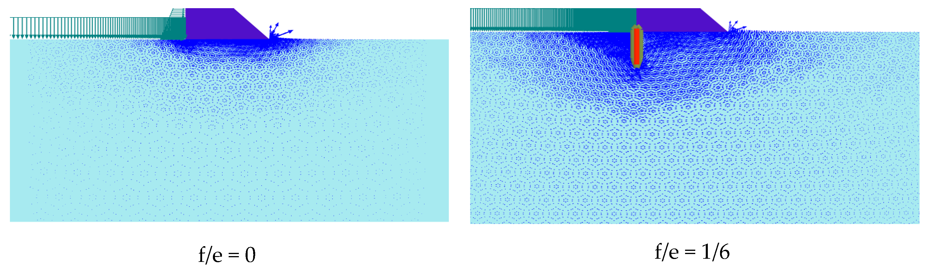
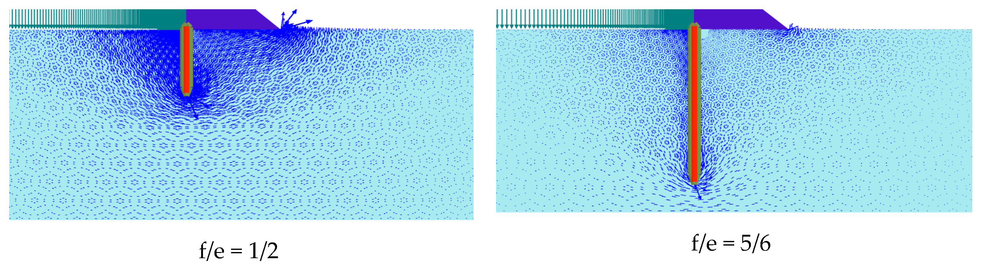
The deeper the cutoff wall, the longer the bypass path length
becomes (
Figure 3).
Increasing the depth of the cutoff wall lengthens the seepage path beneath the structure, resulting in a reduction in the seepage discharge. In a simplified approach, the flow path length can be approximated as:
suggesting an inverse relationship between the discharge
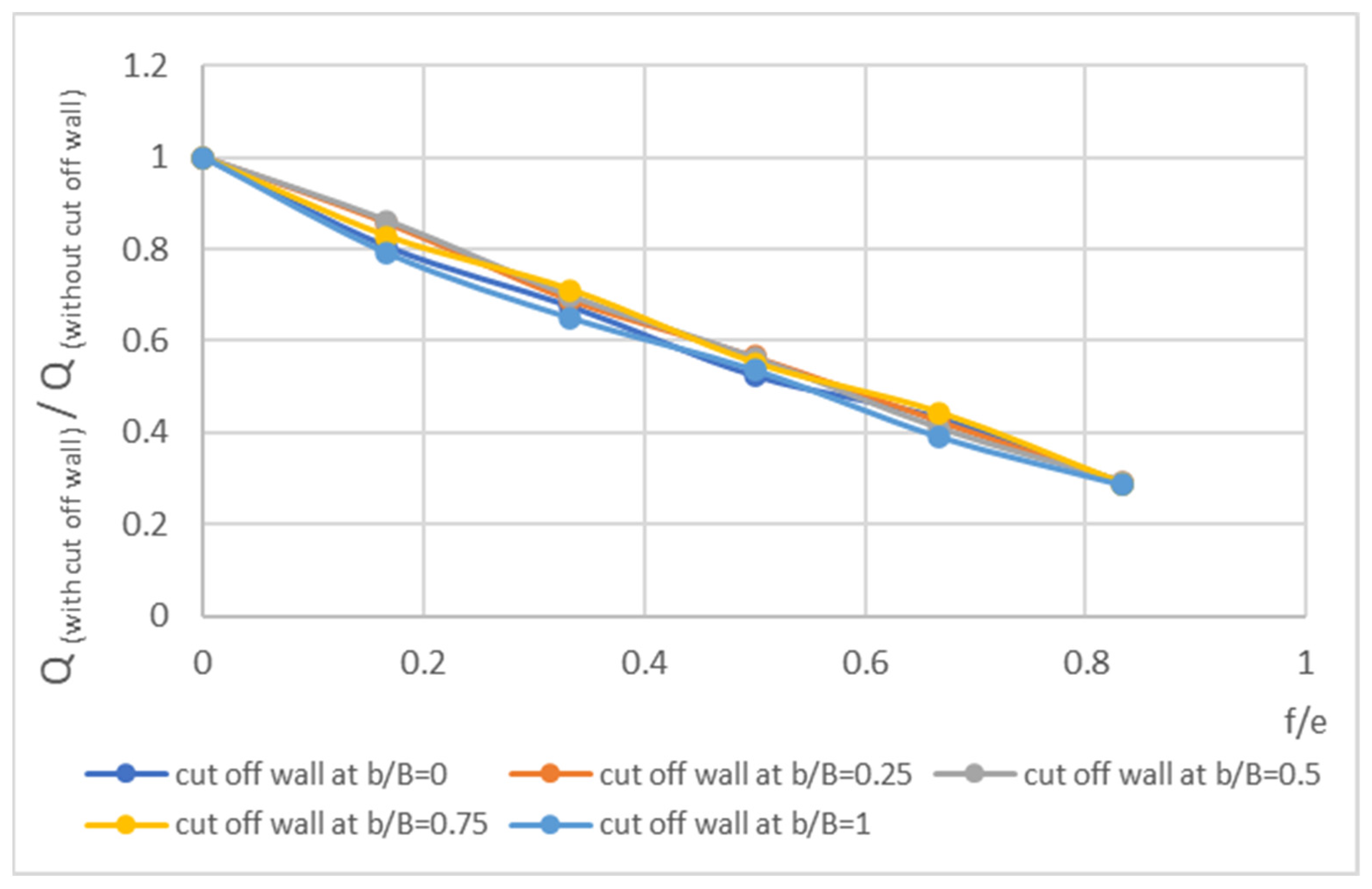
and the wall depth. Consequently, the reduction in discharge exhibits a nearly linear trend with increasing
, particularly for relatively deep cutoff walls. For shallow depths, this relationship deviates slightly from linearity due to the progressive modification of the flow line geometry (
Figure 4).
The results show that increasing the ratio leads to a progressive reduction in the relative seepage discharge. The position of the cutoff wall also affects the hydraulic efficiency of the system. However, the difference in discharge between a wall located at the upstream side and one placed at the center of the dam, although measurable, remains relatively limited. This can be explained by the fact that the critical flow section beneath the foundation is primarily located beneath the cutoff wall and remains generally similar for vertical walls positioned at different locations.
3.2. Analysis of the Influence of Cutoff Wall Position and Depth on Uplift Pressures (P)
The presence and embedment depth of a cutoff wall have a decisive influence on hydraulic behavior, as demonstrated by numerical simulation analyses.
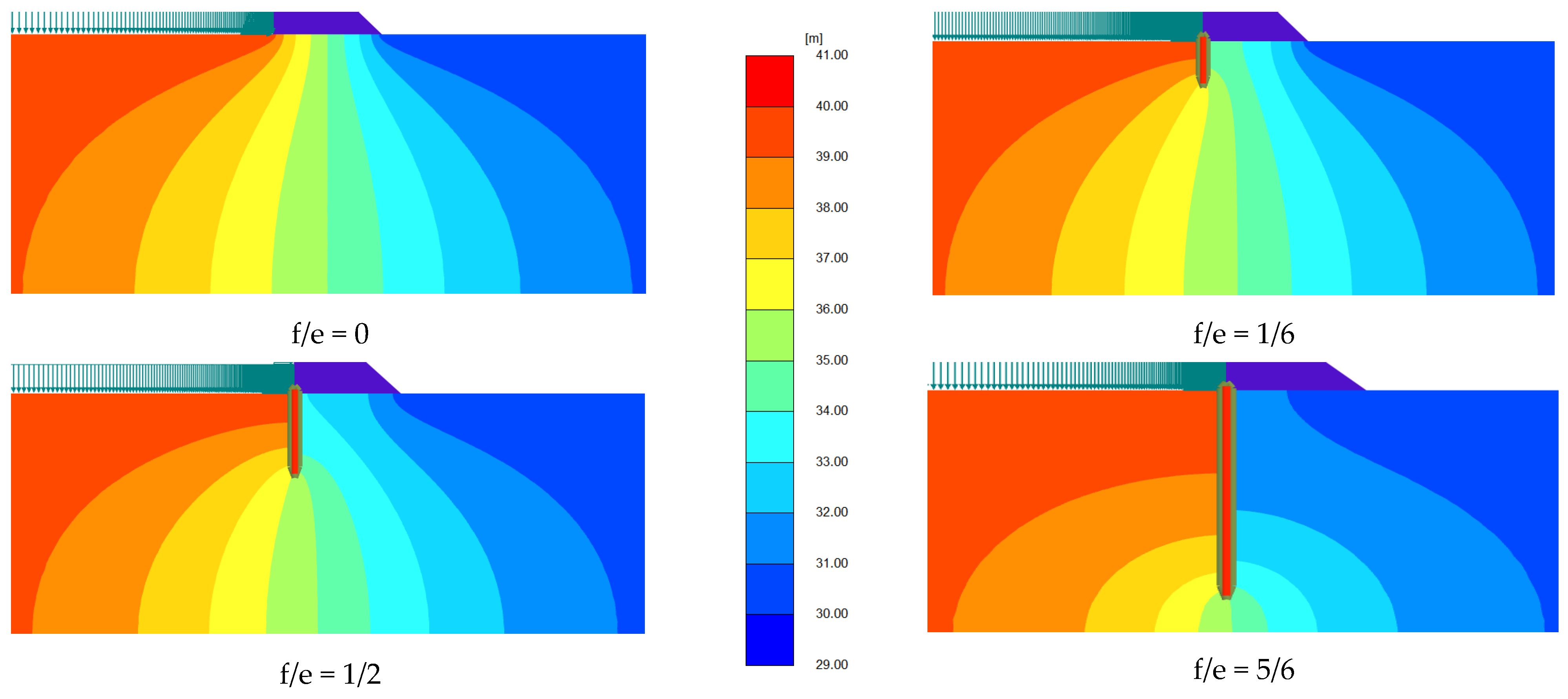
Firstly, the wall substantially modifies the seepage flow. A marked disturbance of the equipotential lines is observed, with the greatest head loss concentrated directly upstream of the structure. It should be noted that the magnitude of this energy dissipation is directly correlated with the depth of the wall: the deeper the penetration, the greater the head loss (
Figure 5).
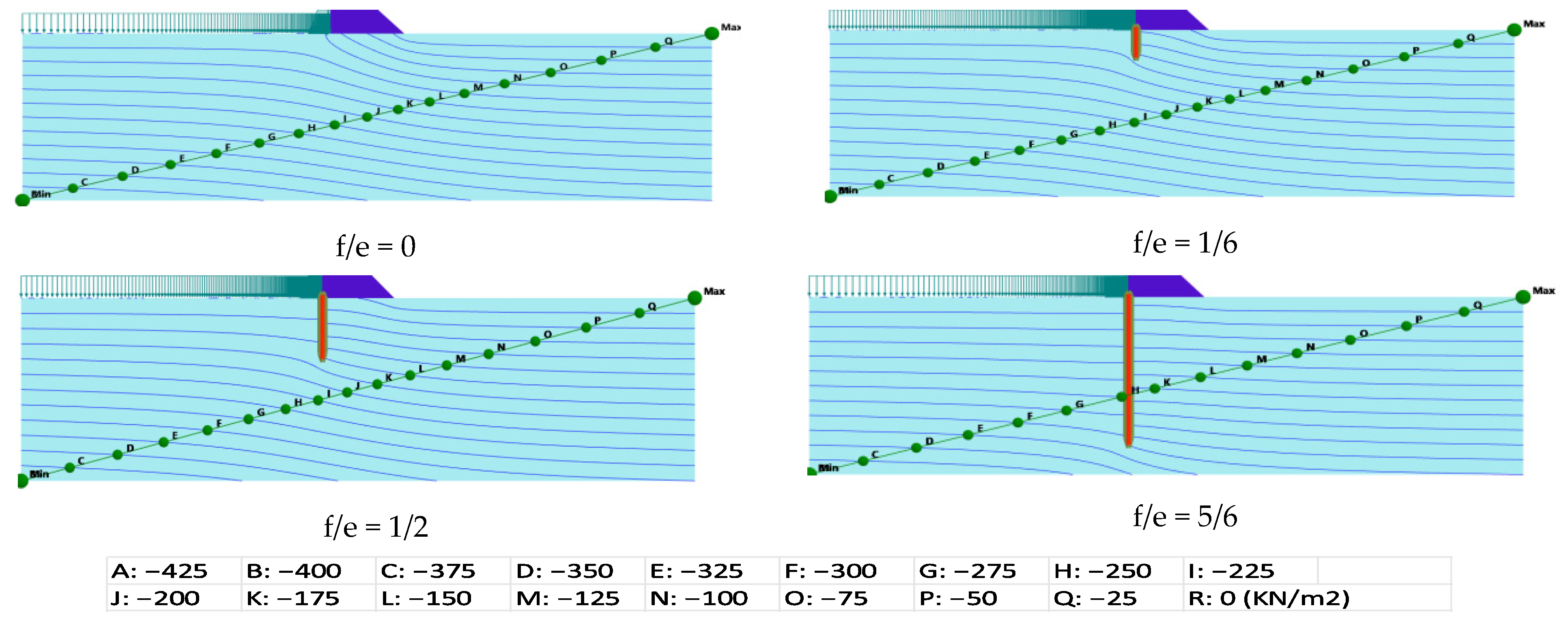
Figure 6 highlights the effect of the cutoff wall on the distribution of uplift pressures (
) beneath the foundation. In the absence of any wall, the uplift pressures are the highest, ranging from −100 to 0 kN/m
2. The introduction of a wall, even with a moderate relative depth (
= 1/6), leads to a significant reduction, with the pressure range shifting to −50 to 0 kN/m
2. This reduction becomes even more pronounced with a greater depth (
= 5/6), where the values are consistently lower than −50 kN/m
2. This demonstrates that the penetration depth of the wall is a key parameter in mitigating this phenomenon.
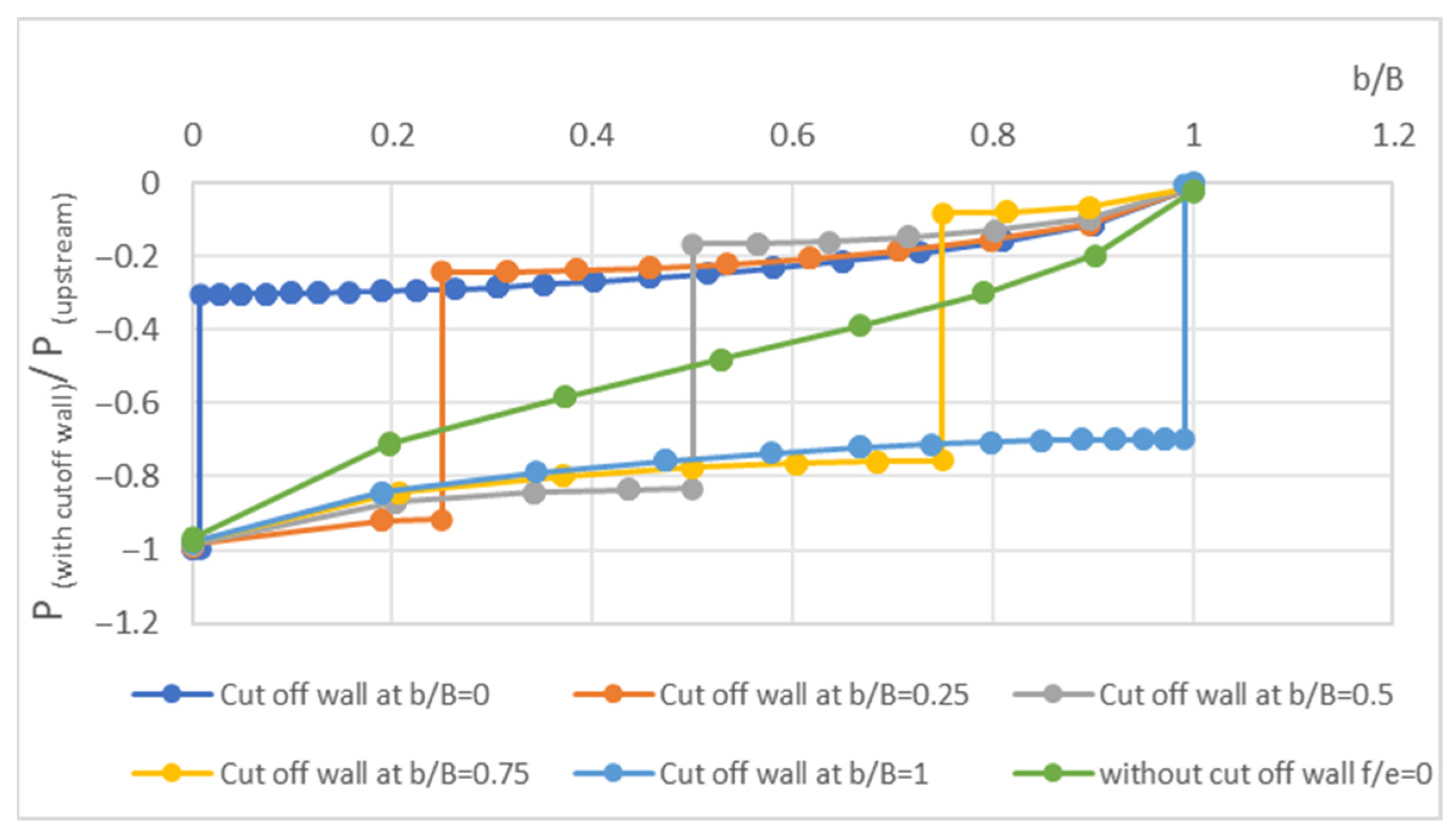
Figure 7 illustrates the influence of the presence of a cutoff wall on the uplift pressure profile along the base of the foundation. The results show that the wall induces a progressive reduction in pore water pressures, particularly in the upstream zone. The greater the relative depth of the wall (
), the more pronounced this reduction becomes.
Except for a slight curvature in the immediate vicinity of the wall (due to the concentration of flow lines), the uplift pressure distribution generally maintains a nearly linear trend toward the downstream side, but at a significantly reduced pressure level. This reduction results from the lengthening of the seepage path and the associated dissipation of hydraulic energy caused by the cutoff wall, which alters the seepage conditions beneath the structure.
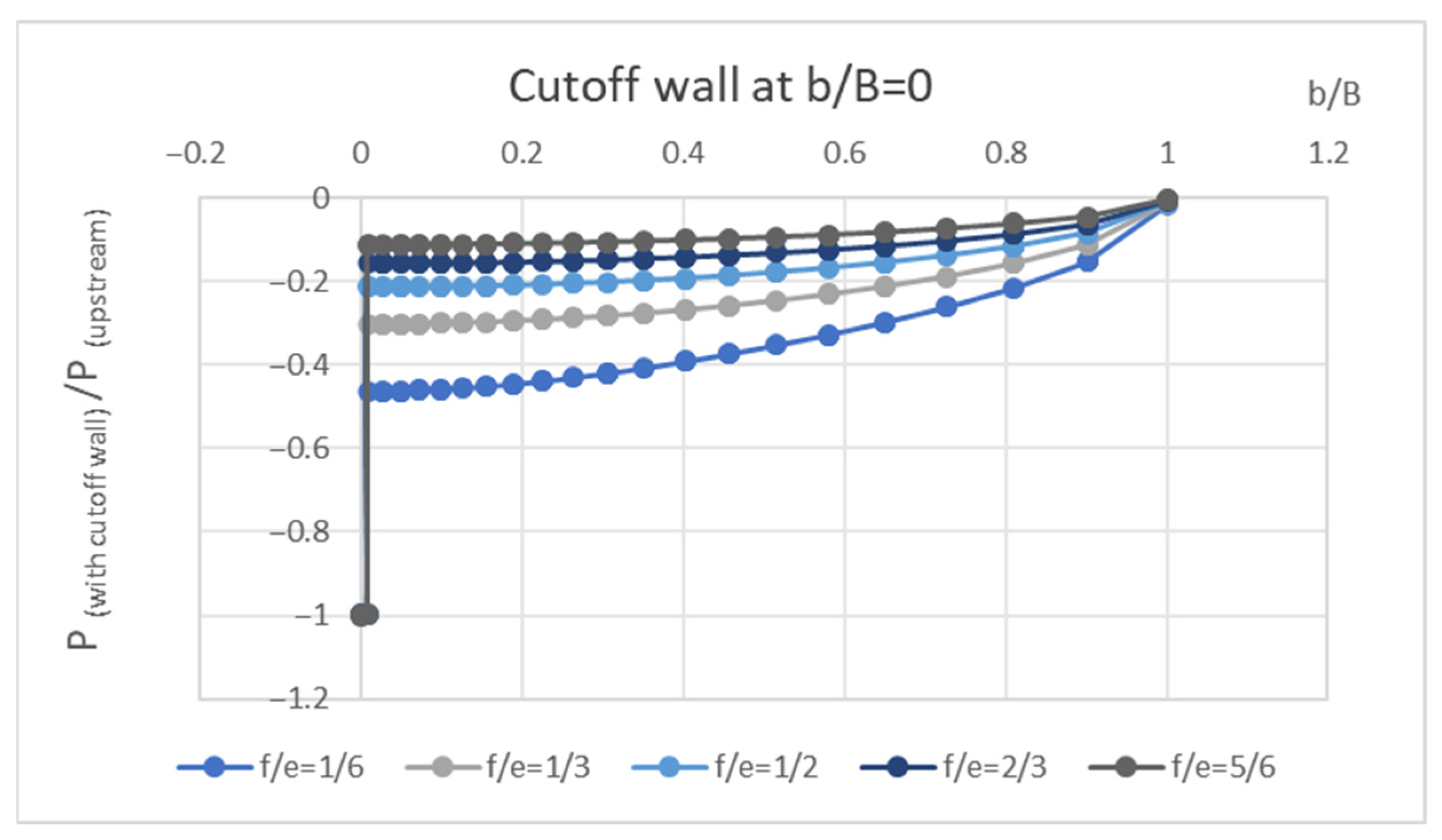
Figure 8 illustrates the influence of the cutoff wall on the uplift pressure profile along the foundation base. The values represent the ratio
, where
is the pore-water pressure at the location
, and
is the pressure beneath the upstream face without a cutoff wall (
).
The results show that the wall induces a progressive reduction in pore pressures, particularly in the upstream zone. The greater the relative wall depth (), the more pronounced this reduction becomes. Except for a slight curvature near the wall (caused by the concentration of flow lines), the overall pressure distribution maintains a nearly linear trend toward the downstream side, but at a significantly lower pressure level. This decrease results from the elongation of the seepage path and the hydraulic energy dissipation induced by the wall, which alters the percolation conditions beneath the structure.
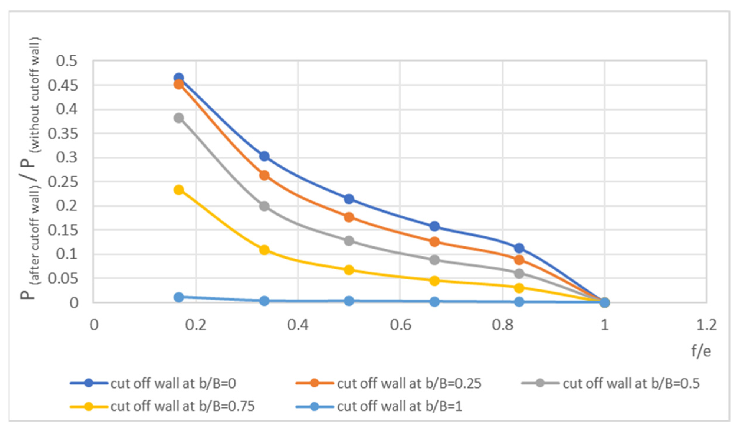
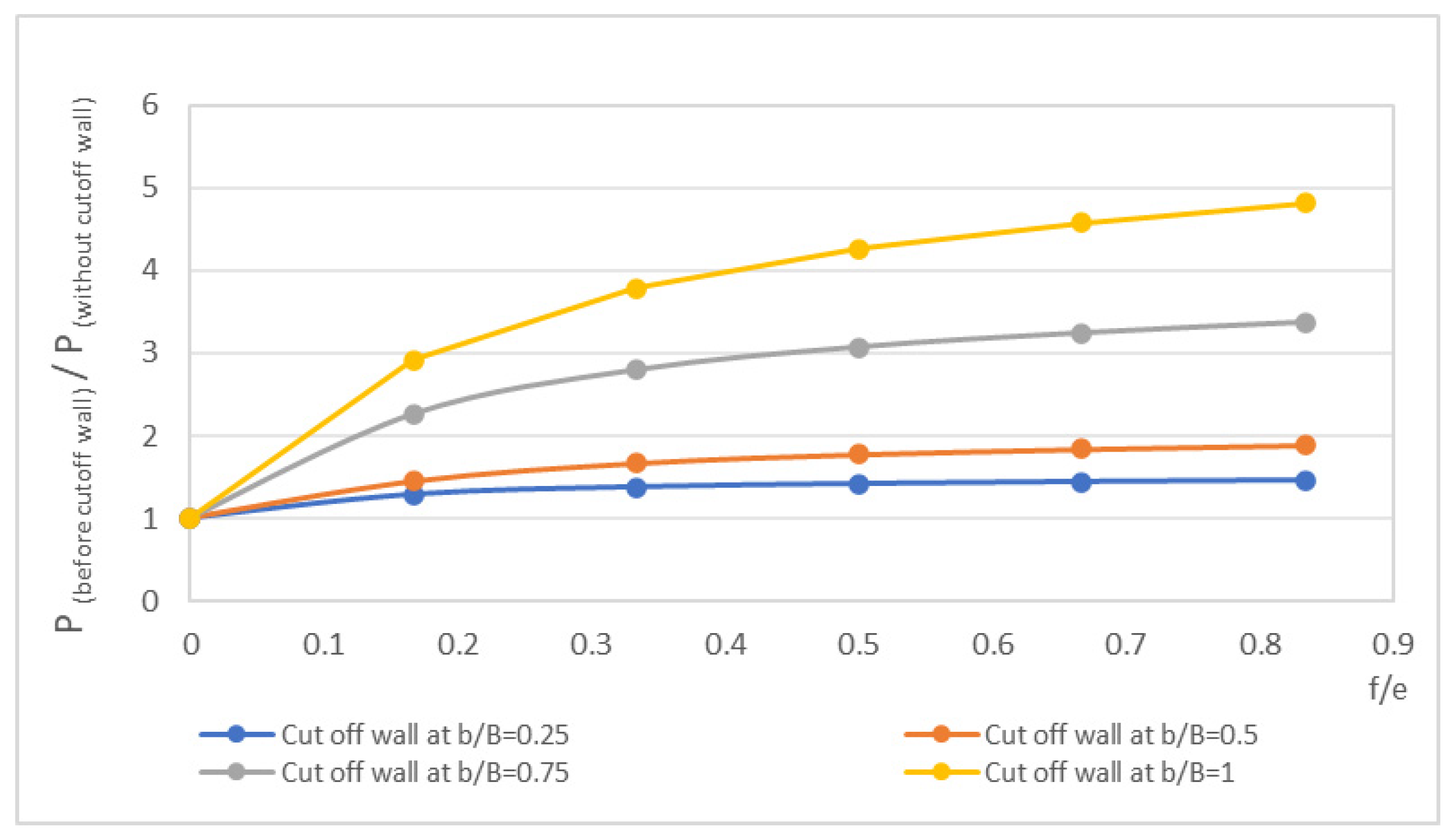
The installation of a cutoff wall within the foundation significantly modifies the pressure field beneath the structure. Two indicators are used to quantify these effects: the upstream pressure increase coefficient, defined as the ratio between the hydraulic head after installation of the wall and the initial head at the same point, and the downstream pressure reduction coefficient, corresponding to the ratio between the residual head and the initial head.
Figure 9 and
Figure 10 illustrate the variation in these coefficients as a function of the relative depth
for different positions of the cutoff wall.
Upstream, the cutoff wall acts as an obstacle to flow, leading to an accumulation of hydraulic head and pressure increase coefficients greater than unity (
Figure 9). This amplification increases with the depth of the wall and becomes particularly pronounced when it is positioned toward the downstream side (
), due to a flow-blocking effect near the exit zone. In contrast, walls located toward the upstream side generate a more moderate increase in uplift pressures, as the head accumulation is more evenly distributed over the upstream domain.
Downstream of the wall, the observed trends are reversed. Cutoff walls positioned upstream intercept the flow lines earlier and promote a gradual dissipation of hydraulic energy along the seepage path. Walls located toward the downstream side exhibit locally smaller pressure drops (
Figure 10), since the head measured immediately after the wall is already close to the downstream head. Therefore, the combined analysis of these two indicators shows that an upstream position of the cutoff wall leads to a more favorable distribution of pressures beneath the structure.
3.3. Analysis of the Influence of Cutoff Wall Position and Depth on Uplift Pressure Forces (F)
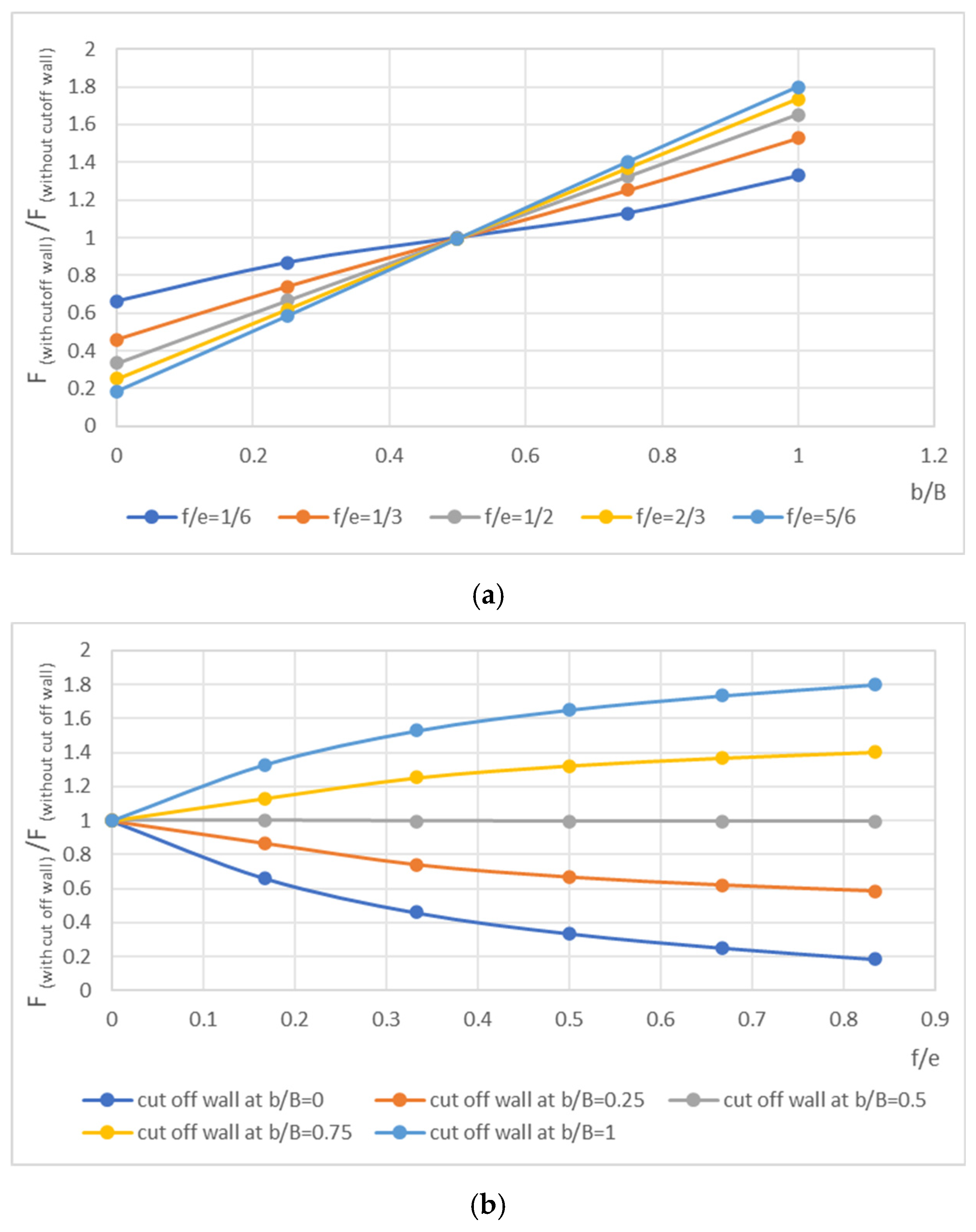
Figure 11a,b illustrate the combined influence of the position and depth of the cutoff wall on the uplift pressure force beneath the dam.
Figure 11a presents the variation in the total uplift force, while
Figure 11b shows the ratio between the uplift force with a cutoff wall and that without a wall, which serves as a direct indicator of the effectiveness of the system.
The results show that increasing the depth of the cutoff wall leads, for all positions, to a progressive reduction in the exit gradient, due to the lengthening of the seepage path. This reduction is particularly pronounced for shallow depths (), where the initial increase in penetration produces the most rapid decrease in the gradient.
However, the effectiveness strongly depends on the position of the wall. Cutoff walls located downstream ( and ) are the most effective in reducing the exit gradient, as their proximity to the flow emergence zone maximizes the extension of the hydraulic path. In contrast, upstream walls ( and ) have a more moderate influence on this parameter, although they contribute more significantly to the reduction in uplift pressures.
For depths , the reduction in the gradient becomes progressively smaller, indicating diminishing returns with increasing depth. Thus, a relative depth of approximately represents an effective compromise for downstream walls, allowing for a significant reduction in the exit gradient without excessive increases in construction costs.
3.4. Analysis of the Influence of the Position and Depth of the Cutoff Wall on the Exit Gradient ()
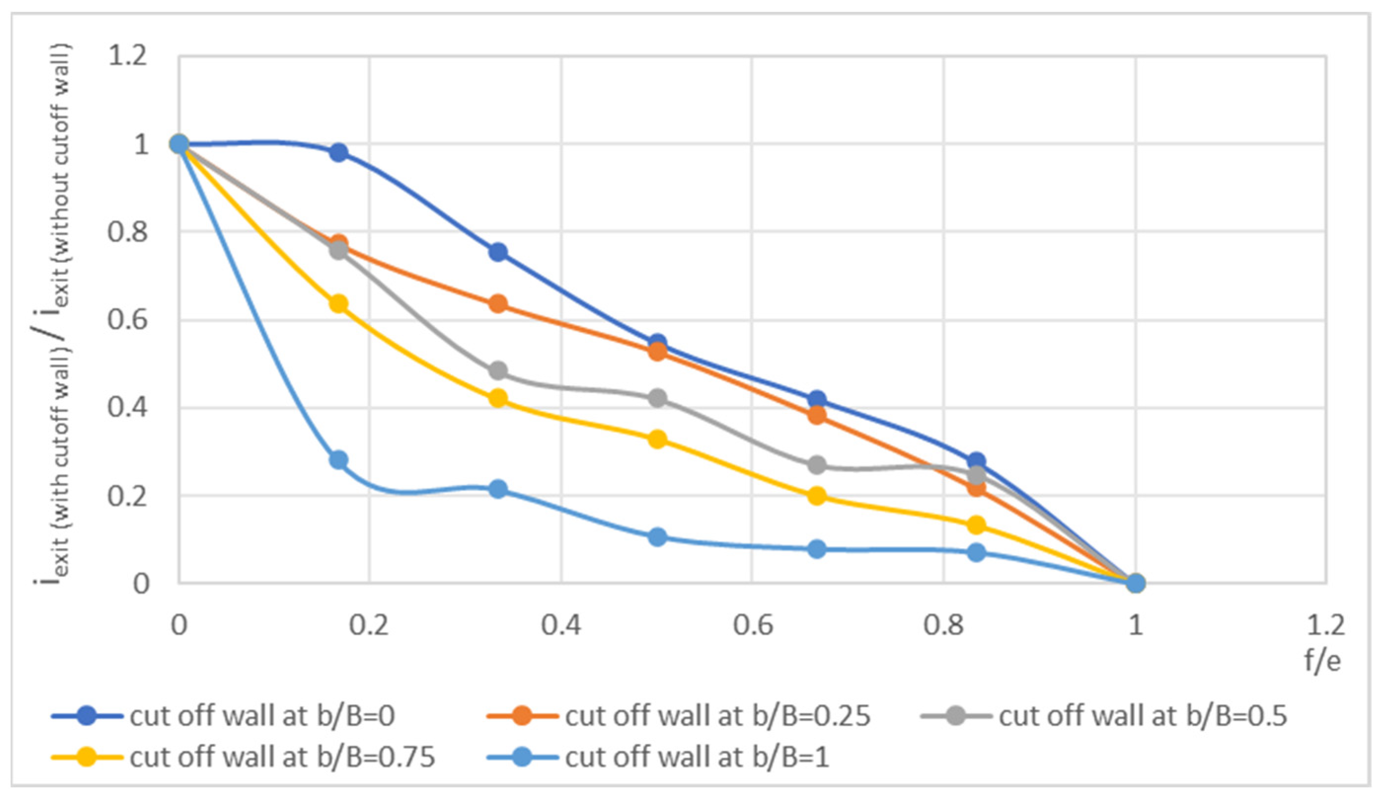
Installing a cutoff wall near the downstream side increases the seepage path length, which in turn reduces the exit hydraulic gradient (
). The presence of a cutoff wall, even if relatively shallow, leads to a significant reduction in this gradient (
Figure 12). The first meters of embedment (for a relative depth f/e < 0.2) are particularly effective in mitigating the phenomenon of piping.
Beyond a relative depth between 0.2 and 0.5, the efficiency of the cutoff wall in reducing the exit gradient decreases: the additional lengthening of the seepage path results in only a marginal reduction in the gradient, especially when the wall is located near the downstream toe of the foundation.
For deeper cutoff walls (f/e > 0.5), the exit gradient reaches a plateau, and the effectiveness of the wall becomes maximal. Beyond this depth, further penetration provides no significant additional benefit in reducing the gradient, while it substantially increases construction costs.
3.5. Effect of the Inclination Angle
It should be noted that although vertical cutoff walls remain the most common, the construction of inclined diaphragms, while more complex, is feasible. Recent advances in construction techniques, along with findings reported in the literature [
24,
25], confirm the potential of such configurations for optimizing hydraulic performance.
The objective of this parametric study is to identify optimal theoretical trends regarding wall inclination, thereby providing a basis for guiding the development of innovative technical solutions and supporting feasibility studies for specific projects.
The inclination angle of the cutoff wall influences the seepage parameters as follows.
3.5.1. On the Discharge
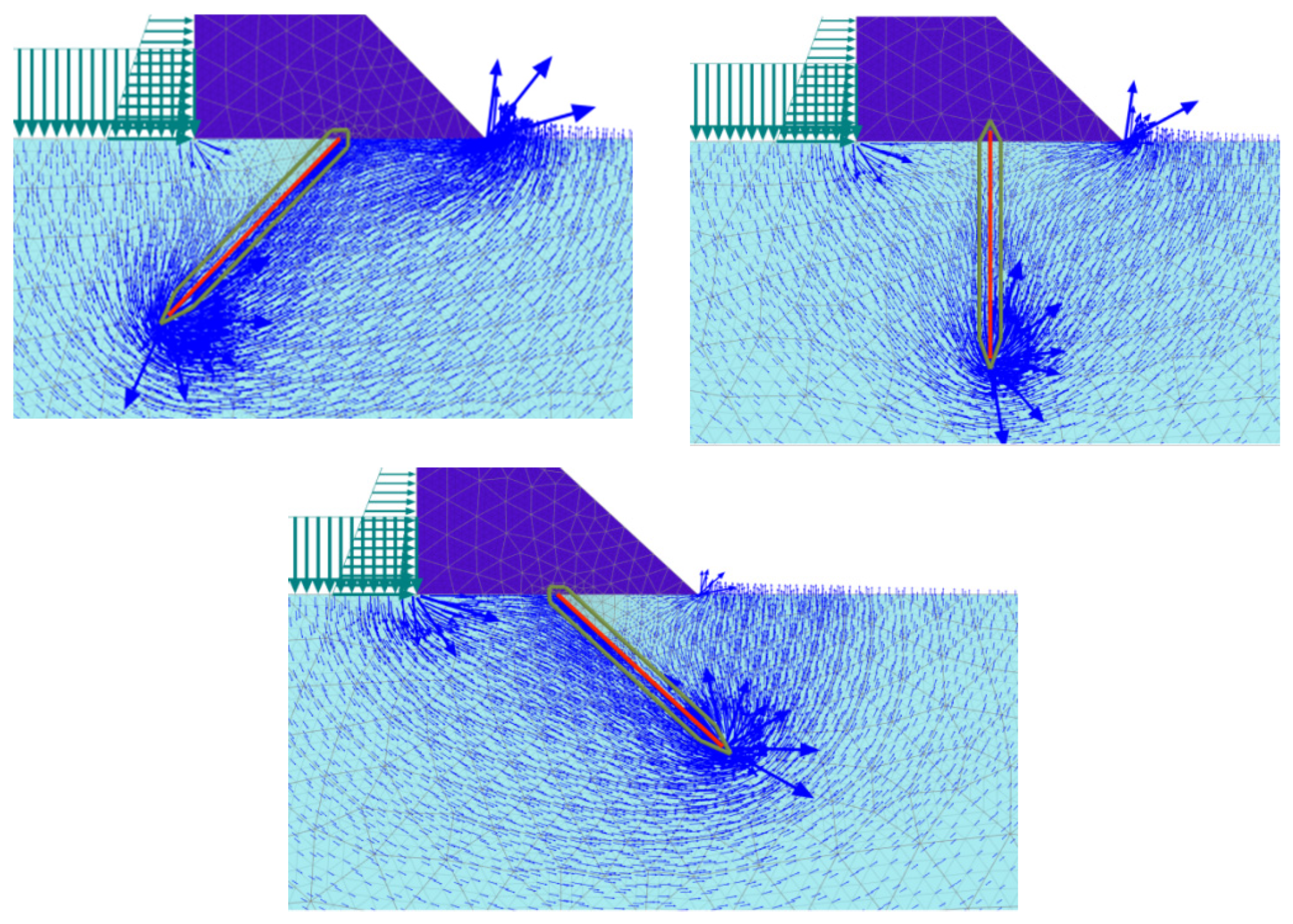
As shown in
Figure 13, the inclination of a cutoff wall has a direct influence on the flow field. It specifically affects the intensity of the streamlines that travel along the surfaces of the wall and the foundation.
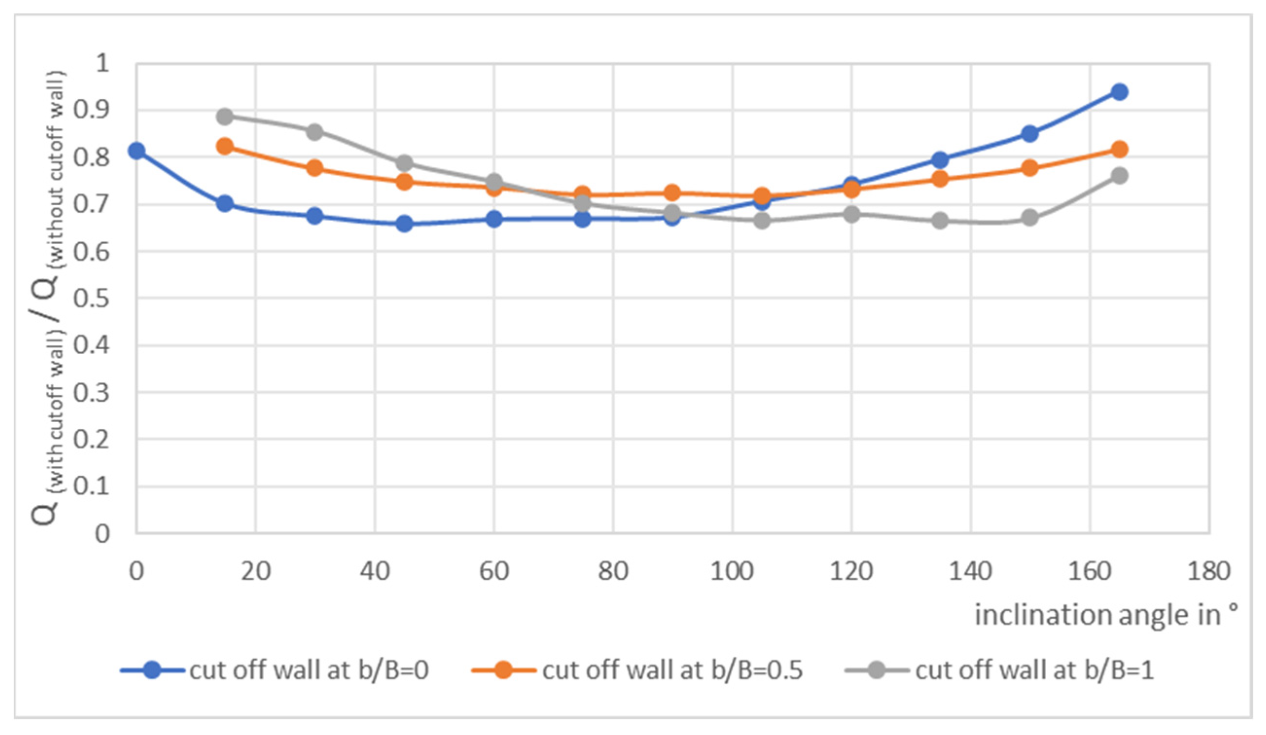
Figure 14 shows that the inclination of the cutoff wall has a limited effect on seepage discharge. An upstream wall, whether vertical or inclined upstream, is more effective in reducing seepage than a horizontal impervious blanket.
Among the upstream-inclined configurations, the wall located near the upstream heel exhibits the lowest seepage discharge, followed by those located at the middle and downstream positions.
When the wall is vertical or nearly vertical (angle between 75° and 105°), its position (upstream, middle, or downstream) does not have a significant effect on seepage.
Conversely, for a wall inclined downstream, the middle and downstream positions result in lower seepage discharge compared with an upstream location.
3.5.2. On the Uplift Pressures
The inclination of a cutoff wall embedded in the foundation directly affects the magnitude of the uplift pressures exerted by water under the base of the structure. Although the spatial distribution of these pressures retains a generally similar shape, their magnitudes vary significantly depending on the angle adopted (
Figure 15).
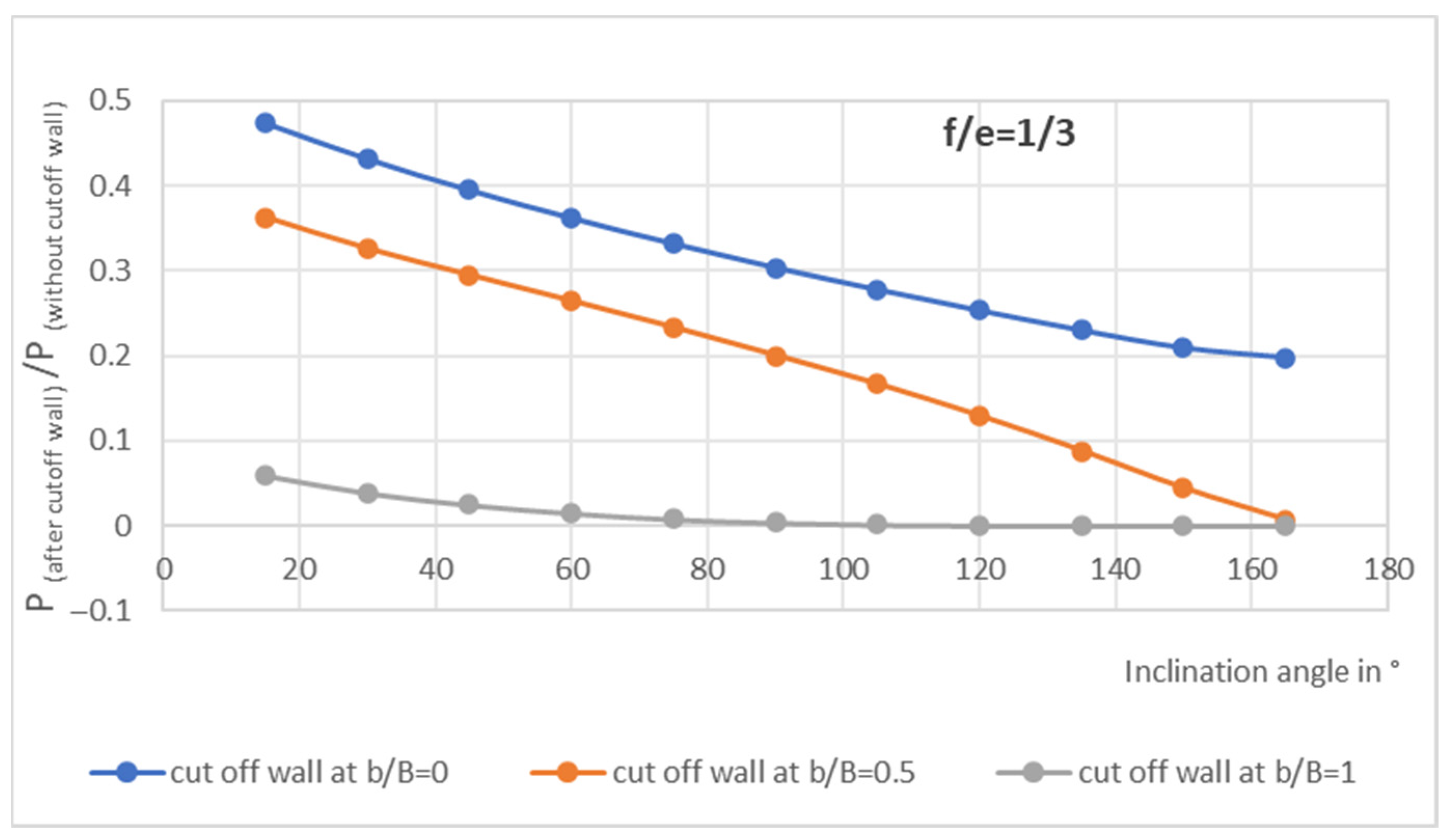
When the cutoff wall is inclined downstream, that is, in the direction of the natural water flow, it plays an active role in managing subsurface seepage. By allowing water to pass more freely beneath the foundation, it reduces local hydraulic resistance and facilitates energy dissipation. This leads to a gradual decrease in uplift pressures downstream of the wall.
This behavior provides an effective technical response to the risk of hydraulic uplift, a critical phenomenon where water pressure can compromise the stability of the structure. In particular, the pressure drop that occurs after the flow passes the wall helps to “relieve” the downstream part of the foundation, which is often the most exposed area to uplift forces.
The relief effect downstream significantly reduces the pressures in the downstream section, as it limits the amount of water seeping under this area.
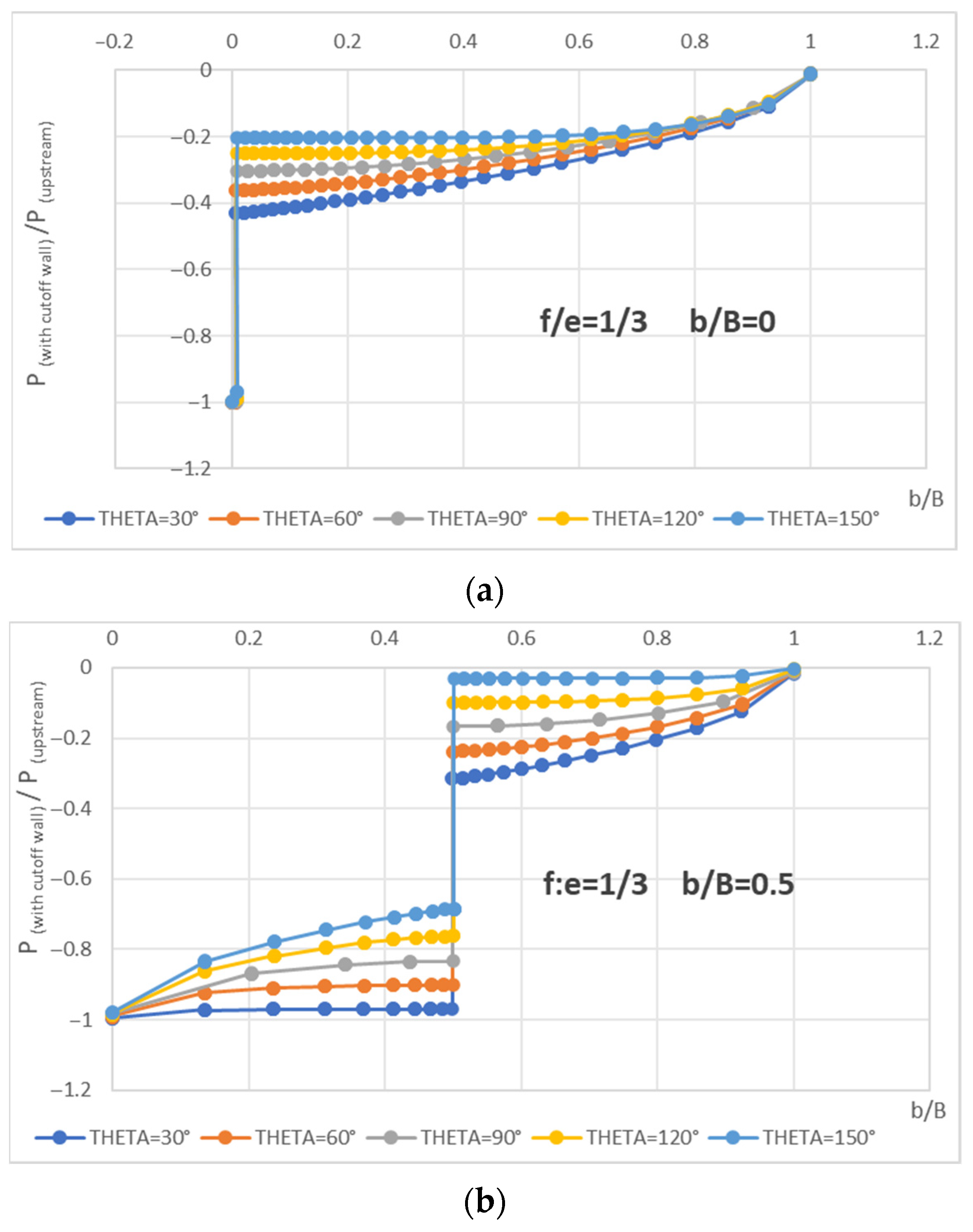
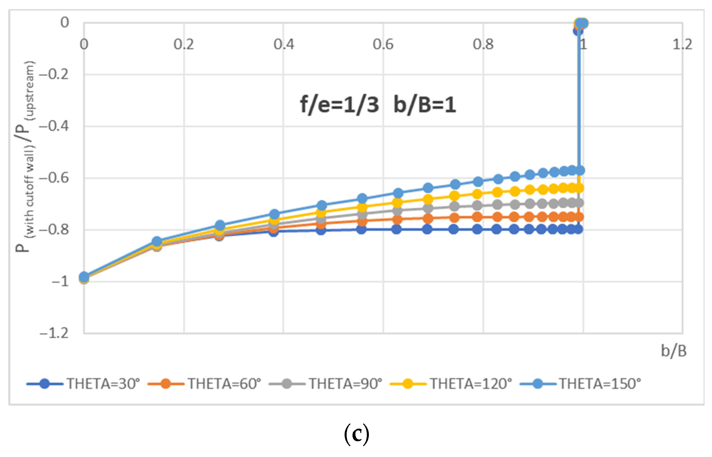
Figure 16 shows that the efficiency of this downstream pressure reduction is not constant; it depends on both the location of the cutoff wall and its inclination angle.
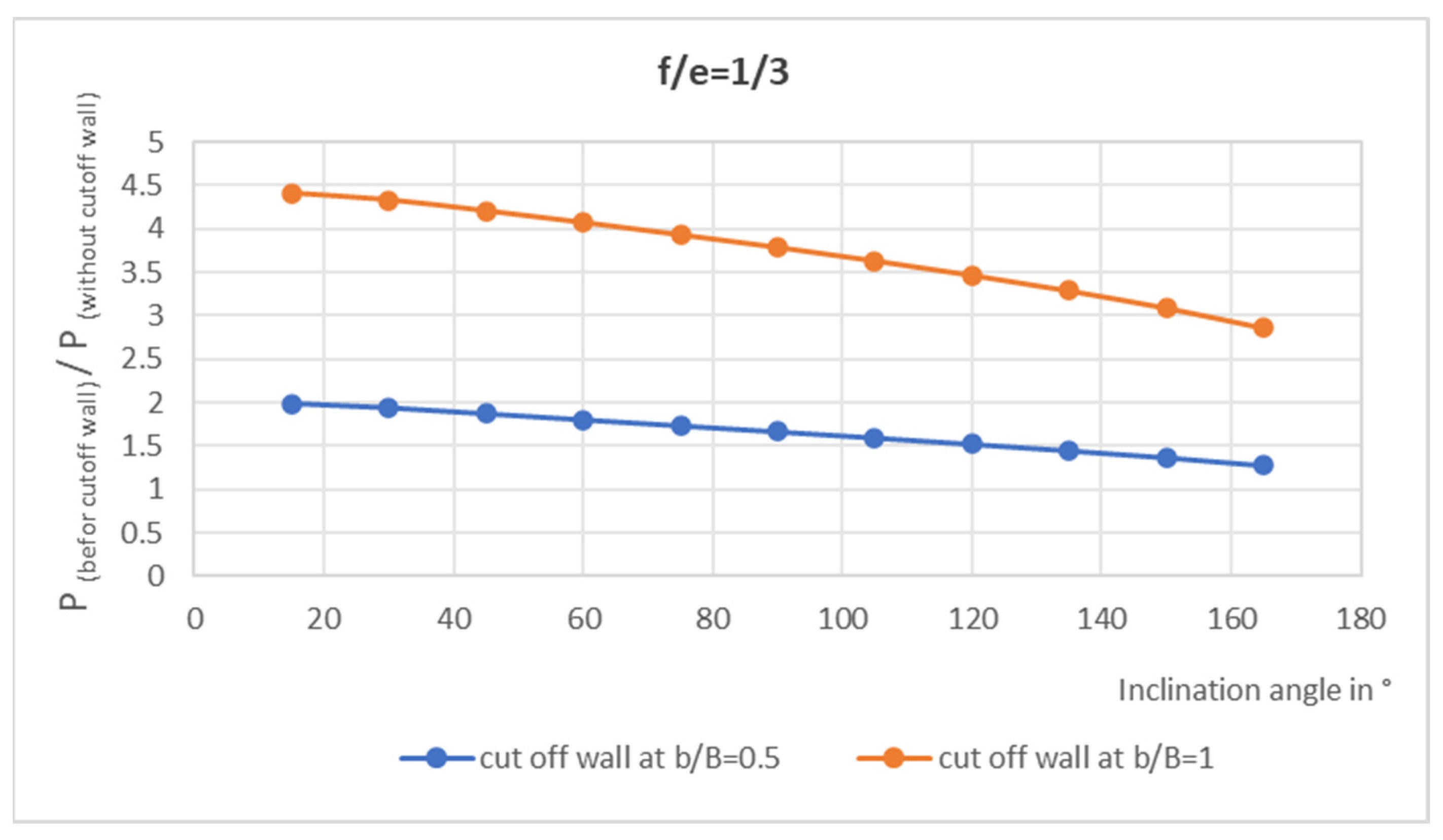
The presence of a cutoff wall modifies the water flow and creates an upstream confinement effect. By partially blocking the passage, the wall causes water to accumulate against its upstream face, which locally increases uplift pressures at this point compared to a scenario without a wall (
Figure 17).
However, inclining the wall downstream helps to mitigate this effect. By orienting the cutoff wall in the direction of flow, the abrupt resistance encountered by the water is reduced. Instead of being strongly trapped, the water is more easily guided along the wall. This facilitated flow relieves the upstream confinement zone and results in a lower pressure coefficient at this location.
3.5.3. On Uplift Pressures
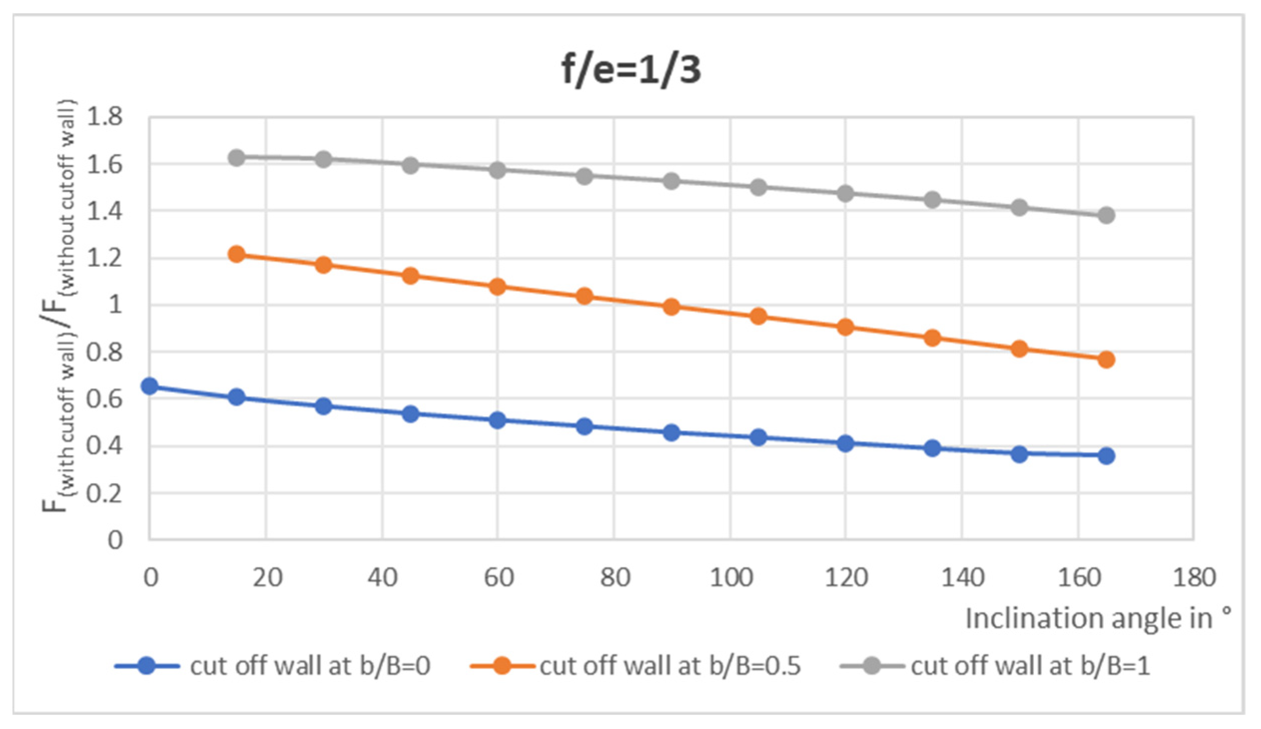
The uplift force (F) generated by pore pressures beneath a dam is sensitive to the inclination of the cutoff wall (
Figure 18). A wall positioned upstream consistently induces the lowest uplift forces, regardless of its inclination.
Conversely, a wall located downstream is not well suited for reducing this force, as it may even lead to higher uplift pressures than those observed without a wall.
A vertical wall placed at mid-foundation has only a limited effect on reducing uplift pressures, though an inclination toward the downstream side can improve its efficiency in this case.
3.5.4. On the Exit Gradient
The value of the exit gradient is highly sensitive to the refinement and density of the numerical mesh. By maintaining the same mesh density for all studied cases, however, a qualitative comparison of the results remains possible.
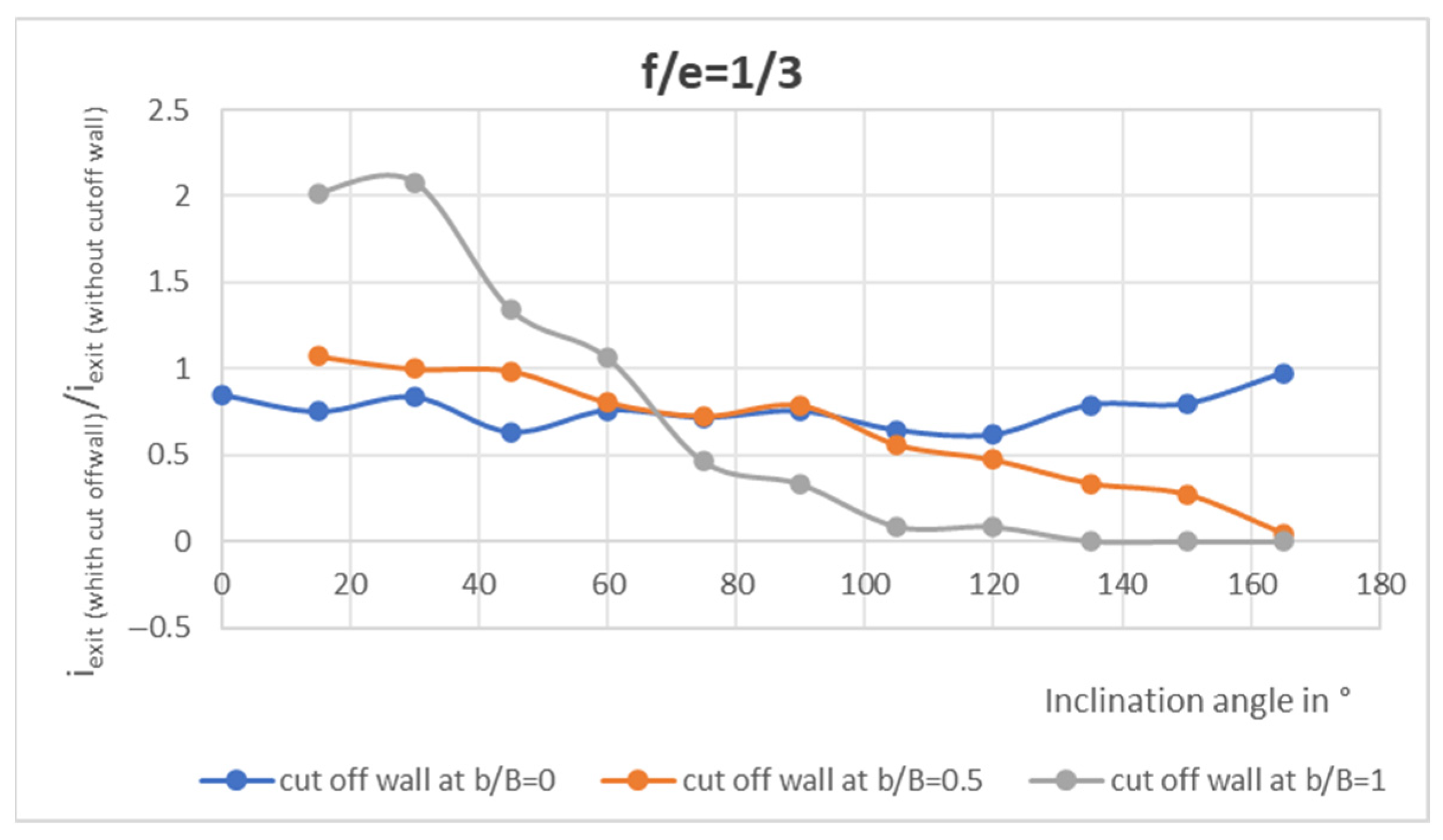
A downstream cutoff wall (whether vertical, near vertical, or inclined downstream) proves to be the most effective solution for protecting the foundation soil and the downstream toe of the dam against piping (
Figure 19). In contrast, a downstream wall excessively inclined upstream should be avoided, as it reduces its effectiveness.
While an upstream wall is only slightly affected by its inclination angle, a mid-foundation wall becomes more reliable for stability when inclined downstream. This configuration promotes a more gradual dissipation of hydraulic head and helps to control uplift pressures.
A previous experimental study, conducted by Praveenkumar et al. [
11], investigated the influence of the inclination angle of a cutoff wall on the uplift pressure generated immediately downstream of it, the seepage discharge, and the exit gradient. In that study, the inclination angle (θ) was varied (45°, 90°, and 120°), while the overall geometry of the structure (including the base width, foundation thickness, and cutoff depth) was kept constant. The general trends observed in that experimental campaign show perfect qualitative agreement with the results of our numerical modeling. Both approaches, therefore, confirm the significant effect of the inclination angle θ on uplift pressures, seepage discharge, and exit gradient. However, a detailed quantitative comparison, aimed at matching specific numerical values, could not be performed. This limitation is due to the unavailability of certain experimental data required for a rigorous numerical correlation.
4. Limitations of the Study and Future Research Directions
This study is based on several simplifying assumptions (homogeneous and isotropic foundation, two-dimensional modeling, steady-state flow, and impermeable cutoff wall), which do not fully capture the geological and hydraulic complexities of real sites (heterogeneity, anisotropy, three-dimensional effects, transient regimes, and non-Darcian flows). These choices were made deliberately to isolate the influence of the fundamental geometric parameters and to establish robust and transferable trends.
The model, therefore, captures the dominant mechanisms governing the flow–cutoff wall interaction, and the results are expressed in relative terms to ensure their applicability across a wide range of geotechnical configurations. The absence of dam embedment represents a conservative assumption, as it leads to higher exit gradients, placing the analysis on the safe side with respect to internal erosion risks.
As an indication, comparison with Terzaghi’s critical gradient (
for a typical sand, and
, with a safety factor of 3) shows that the configurations identified as optimal provide satisfactory safety margins under common geotechnical conditions. For soils susceptible to suffusion, the application of reduction factors [
28] would further reinforce this conservative character.
Beyond these modeling assumptions, the parametric study also warrants consideration of construction constraints. With the dam foundation being horizontal, the inclination angle is measured with respect to the horizontal. In cohesionless soils, the construction of a diaphragm wall imposes a limited range of inclination, typically between 75° and 105° (i.e., a deviation of 10° to 15° from the vertical), beyond which trench stability can no longer be ensured. For a grout curtain, larger inclinations may be considered, typically between 55° and 120° (i.e., a deviation of 25° to 30° from the vertical), provided that strict control of borehole deviation is maintained. Outside these ranges, implementation would require specific support systems, which limit the practical applicability of the conclusions drawn from the parametric analysis.
Beyond these acknowledged limitations, the study opens up promising perspectives. The established parametric relationships can serve as a foundation for more advanced modeling approaches, including heterogeneous foundations, three-dimensional geometries, transient flow conditions, and interactions with additional control measures (such as drains and upstream blankets).
More importantly, this work aligns with current trends toward the integration of artificial intelligence and digital twins in the management of hydraulic structures. Approaches such as MMGPT4LF [
29] demonstrate how simulations and textual data can be combined to support decision-making, while drone-based inspections coupled with deep learning [
30] are already contributing to real-time digital twin systems. More broadly, recent advances in language models for predicting complex systems [
31], in efficient architectures for processing and restoring multidimensional data [
32], as well as in innovative techniques for measuring and monitoring structural stresses [
33], confirm the potential of these integrated approaches. By providing a quantitative basis for the influence of cutoff wall geometry, this study contributes to the development of next-generation tools for predictive monitoring and optimized design.