Article

Mock-Up Test of Cast-in-Place Tunnel Lining for TBM Method

1
Faculty of Civil Engineering, Czech Technical University in Prague, Thákurova 7, 166 29 Prague, Czech Republic
2
HOCHTIEF CZ a.s, Plzeňská 3217, 150 00 Prague, Czech Republic
*
Authors to whom correspondence should be addressed.
Infrastructures 2026, 11(3), 78; https://doi.org/10.3390/infrastructures11030078
Submission received: 16 December 2025 / Revised: 9 February 2026 / Accepted: 12 February 2026 / Published: 27 February 2026

Abstract

Segmental tunnel linings represent a conventional method commonly employed in tunnel boring machine (TBM) operations. However, this approach presents notable limitations, including handling challenges and the presence of numerous joints prone to leakage. An alternative method involving cast-in-place tunnel lining was experimentally investigated through a scaled mock-up test conducted at approximately 1:4 scale, with a total length of 0.85 m and 2 m lining diameter. In this setup, two reinforced concrete rings were constructed to simulate the surrounding geological conditions and internal formwork. Fiber-reinforced concrete was then pumped into the annular space between the rings, forming a cast-in-place lining with a thickness of 170 mm. To replicate the thrust force exerted by hydraulic actuators of a TBM, a hydrostatic pressure up to 5 MPa was applied from the front side. The experiment demonstrated a linear compaction of fresh concrete by approximately 3%, greater resistance to compaction in the lower section, and a uniformly well-compacted concrete structure throughout the entire volume.

1. Introduction

The aim of this project was to develop a novel type of cast-in-place tunnel lining for use with a tunnel boring machine (TBM), also known as a cutting shield. This technology was previously tested and implemented in the Czech Republic during the 1970s, particularly in the construction of parts of Prague Subway Line A, in the Malostranská–Staroměstská section beneath the Vltava River, to improve impermeability [1]. Expertise from engineers involved in the original work was utilized in this effort. However, due to technical complexity and unresolved issues at the time, further application of the method was abandoned.
The development of this technique is closely tied to research conducted in Europe and Japan [1,2,3], where similar approaches were employed in the last century. Later applications have been documented in subsequent studies [4,5,6,7]. Advances in technical capabilities have since mitigated earlier limitations, enabling the development of a next-generation cast-in-place lining with superior performance characteristics; see [8,9,10,11].
The use of knowledge from the hydro shield and extruded concrete lining for the Rhone and Saone underpass in Lyon, France, including other practical guides [11,12,13,14,15,16], was used to implement a mock-up experiment.
The basic types of tunnel boring machines (TBMs) are divided according to their application in given geotechnical conditions and according to the requirements for ensuring the stability of the excavation and deformation of the overburden. Each type is optimized for a specific application of the machine in specific geotechnical conditions. The selection and modification of the tunnel boring machine is essential for practical use for cast-in-place tunnel lining [16,17,18,19,20,21,22,23]. Information and procedures on prefabricated segments, which are an alternative for use in practice, are mentioned in [24,25,26].
A key technical advantage of the cast-in-place tunnel lining approach lies in its elimination of the complexities associated with the handling and assembly of individual segments, which are characteristic of conventional segmented lining systems. In traditional segmented configurations, each segment is subjected to considerable mechanical stress during tunnel excavation, frequently leading to cracking, faulty joints, and a subsequent degradation in structural performance [27,28,29]. The cast-in-place method mitigates these issues by allowing the fresh concrete to be compacted under controlled pressure within the formwork, thereby substantially reducing the risk of cracking. An additional benefit of this system is the absence of longitudinal joints—aligned with the tunnel axis—that typically serve as structural vulnerabilities in segmented linings. Instead, only transverse joints are present between consecutive rings, which can be effectively sealed using rubber gaskets to improve watertightness. Nevertheless, the implementation of this technique necessitates specific modifications to the TBM excavation shields. Although such adaptations are technically feasible with current manufacturing capabilities, they extend beyond the defined scope of the present study.
For the realization of this technology, several critical technical challenges needed to be addressed. These include the following:
  • Optimizing the pumping of the reinforced concrete mixture to ensure uniform filling while minimizing defects, voids, and fiber segregation. The experiments and studies described in [30,31] inspired the solution.
  • Evaluating the behavior of the fiber-reinforced concrete mixture under pressure of up to 5 MPa, replicating the load exerted by TBM support cylinders on the cast-in-place lining.
  • Investigating the response of the lining during hydration, including phenomena such as autogenous shrinkage and heat generation.
  • Conducting a thorough evaluation of the hardened state of the cast-in-place lining to confirm its structural integrity and performance.

2. Materials and Methods

The listed shortcomings are largely eliminated by the combination of the technological excavation process, the method of implementing the cast-in-place lining, and the material composition of the composite used.

2.1. Excavation Method

A tunnel boring machine (TBM) is intended for excavation, chosen for its efficiency, safety, and minimal surface disruption. The TBM would advance 20–36 m per day, depending on ground conditions, maintenance, and logistics. Continuous monitoringwould ensure proper alignment and structural stability.
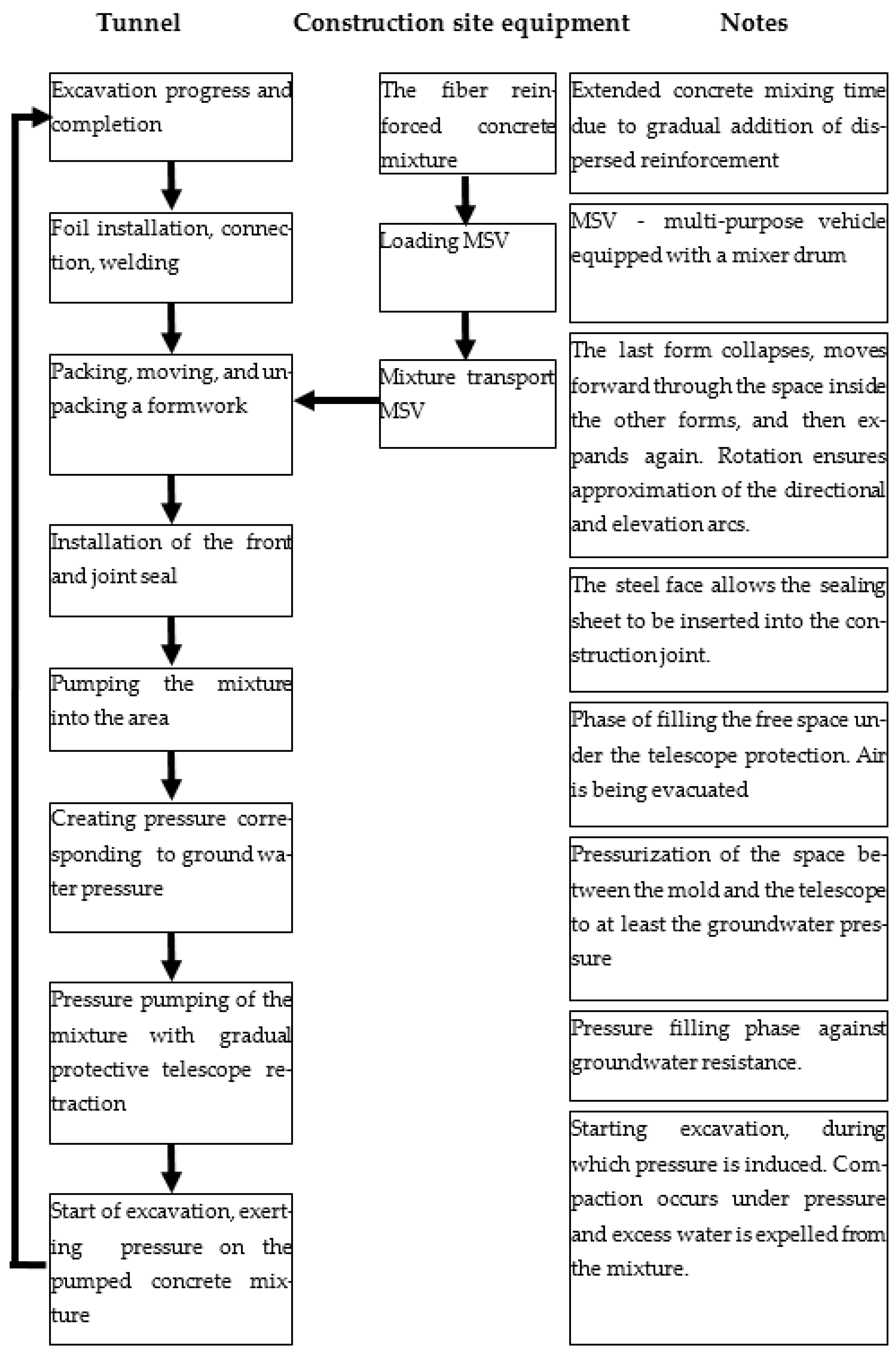
After excavation, a cast-in-place lining provides strength and water resistance. The lift of approximately 2 m will allow for quality control and efficient coordination with excavation. The process is designed to minimize downtime and maintain high productivity and safety throughout construction see Figure 1.

2.1.1. Profile Tunnels

The cast-in-place lining ensures long-term tunnel strength and waterproofing, installed in sync with TBM excavation for continuous and safe progress. During concrete placement, the TBM acts as a temporary support until the lining gains strength, aided by telescopic formwork to maintain profile stability and absorb ground pressure.
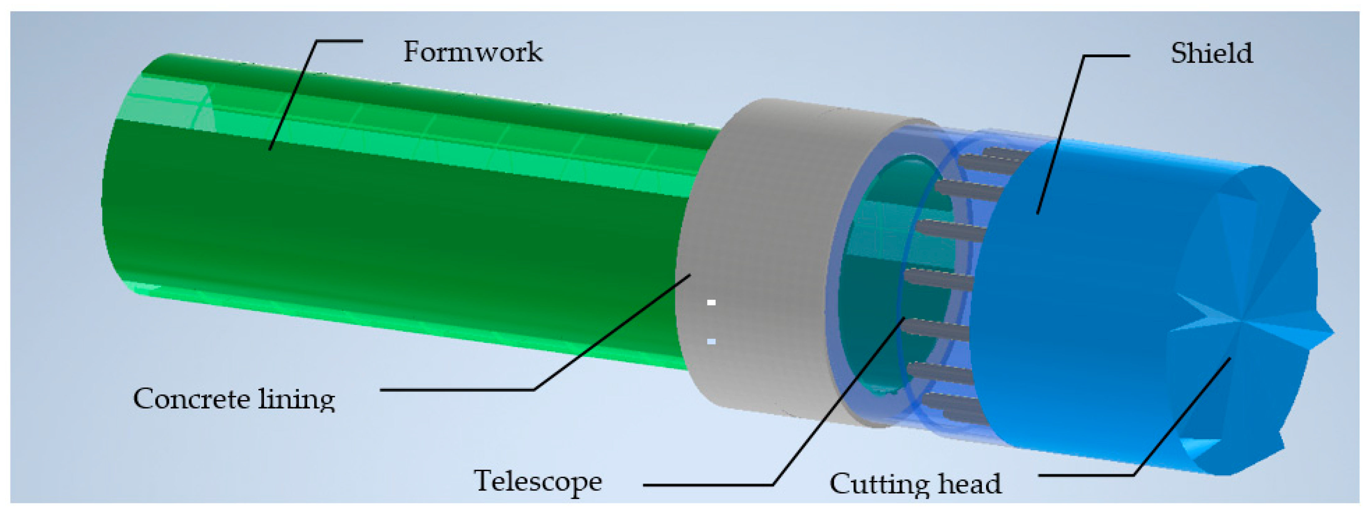
The rock pressure is transmitted by the shield, the telescope, then the concrete supported by the form.
A protective foil membrane is placed between ground and lining to prevent groundwater seepage and enhance waterproofing. The lining is built in 8 m3 rings, poured in one operation via 10 m3 truck mixers and pumped through 125 mm pipelines at up to 6 bar. This process ensures consistent quality, avoids cold joints, and maintains efficient cycle-based construction.

2.1.2. Mixing, Transporting, and Pumping Process

The process involves 20 min of mixing, 30–45 min of transport by mixer truck, and 30 min of pumping. Concrete setting takes 45 min, aided by the machine’s pressure rollers and mold heating using waste heat from the excavation machine’s cooling water. Once hardened, the front face is removed, with the concrete already compressed and set, greatly reducing the risk of leakage.

2.1.3. Procedure of Method

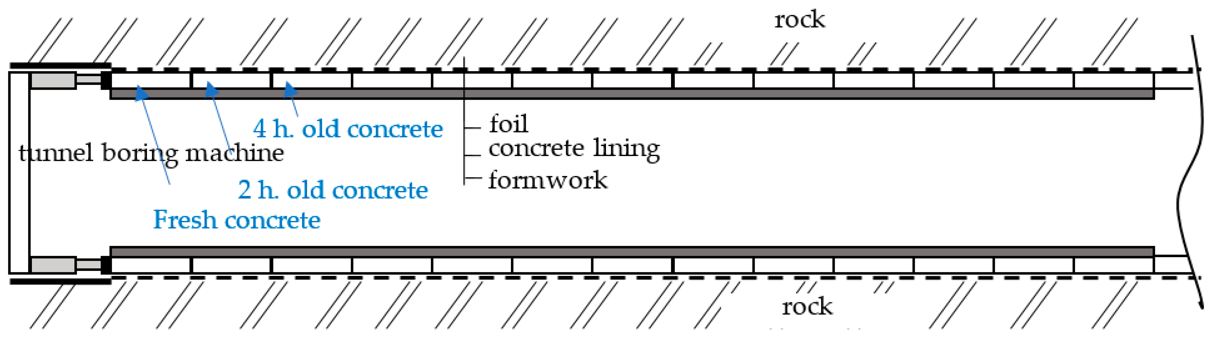
After a punching phase ends, the hydraulic pistons pushing the punching shield are fully extended. They are then retracted, allowing the last mold segment to fold and move forward. The segment is unrolled at the front, creating space for concreting a new lining ring.
Concrete placement begins under the protective telescope. Once the gap between the formwork and telescope is filled, the telescope retracts while pumping continues, filling the newly exposed space (overcut). When the telescope is fully retracted, the void between the formwork and surrounding rock is completely filled with concrete.
The next excavation cycle starts; the cutting head rotates, and the hydraulic pistons extend, pushing against a plunger. Simultaneously, the telescope extends to shield the growing gap between the formwork and the excavation shield. When excavation ends, the pistons are again fully extended, and the cycle repeats.

2.1.4. Model of Technology

A 3D model of technology was created in 2023. The models were created based on the Scheme of technology, shown below in Figure 2; the 3D model is presented in Figure 3.

2.2. Material

The concrete used in the mock-up has a strength class of at least C45/55 and a compressive strength of at least 15 MPa after 16 h after being pumped into the formwork; see Table 1. The concrete contains steel fibers at least 50 kg/m3 with the length of 50 to 65 mm and a diameter of 0.5 to 0.9 mm. The rheology of such a composite mixture, measured by settling on an Abrams cone, is between 200 and 240 mm. The workability of such a mixture is defined by a value of 110 min and the beginning of setting at least 2.5 h after pumping into the formwork.

3. Results and Discussion

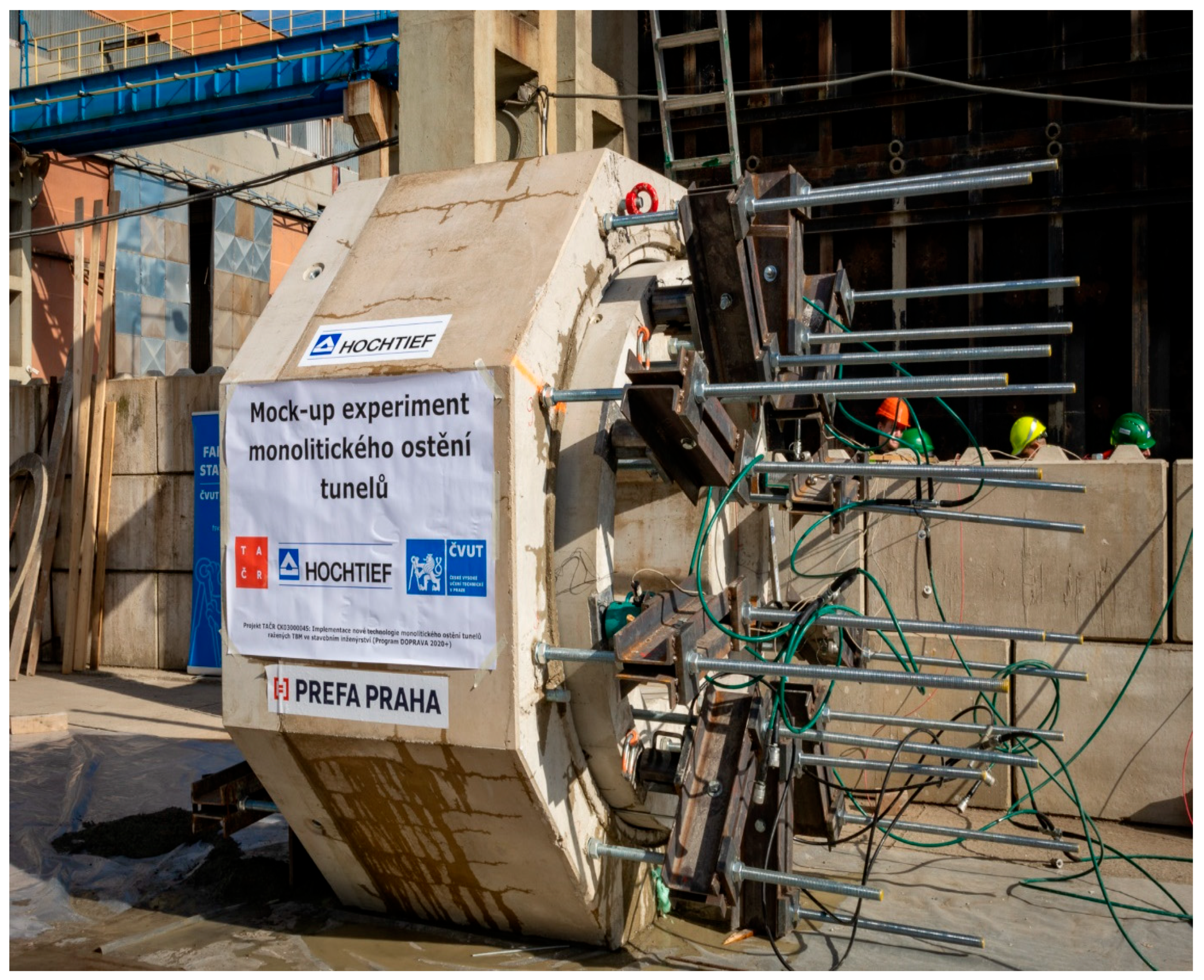
The 1:3 scale mock-up model with a 2 m lining diameter section, representing a metro tunnel, was built and tested at Prefa Praha a.s. in October 2024. The trial evaluated the entire concreting process—from pumping fiber-reinforced concrete into the formwork to simulating excavation-related loads.
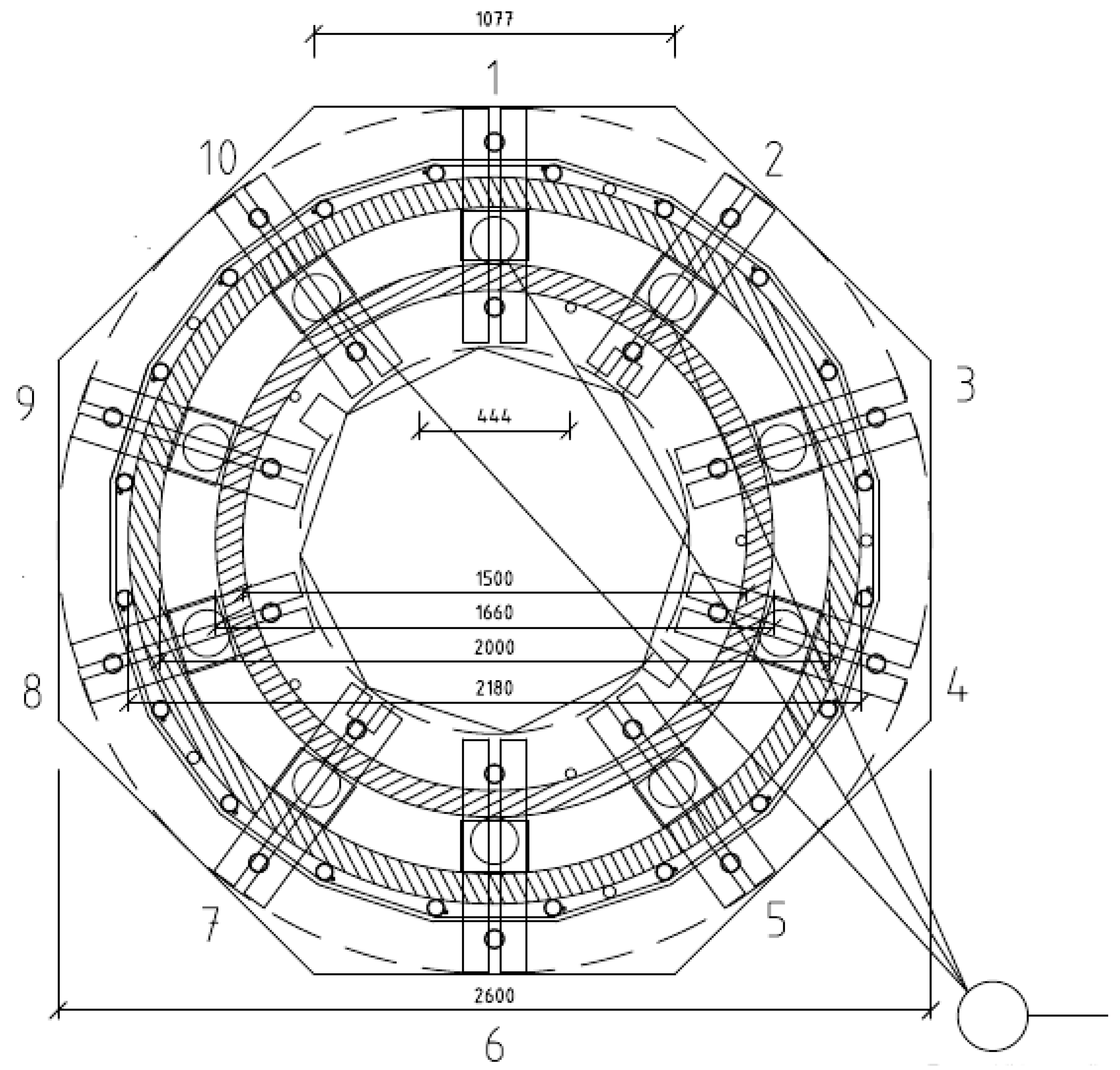
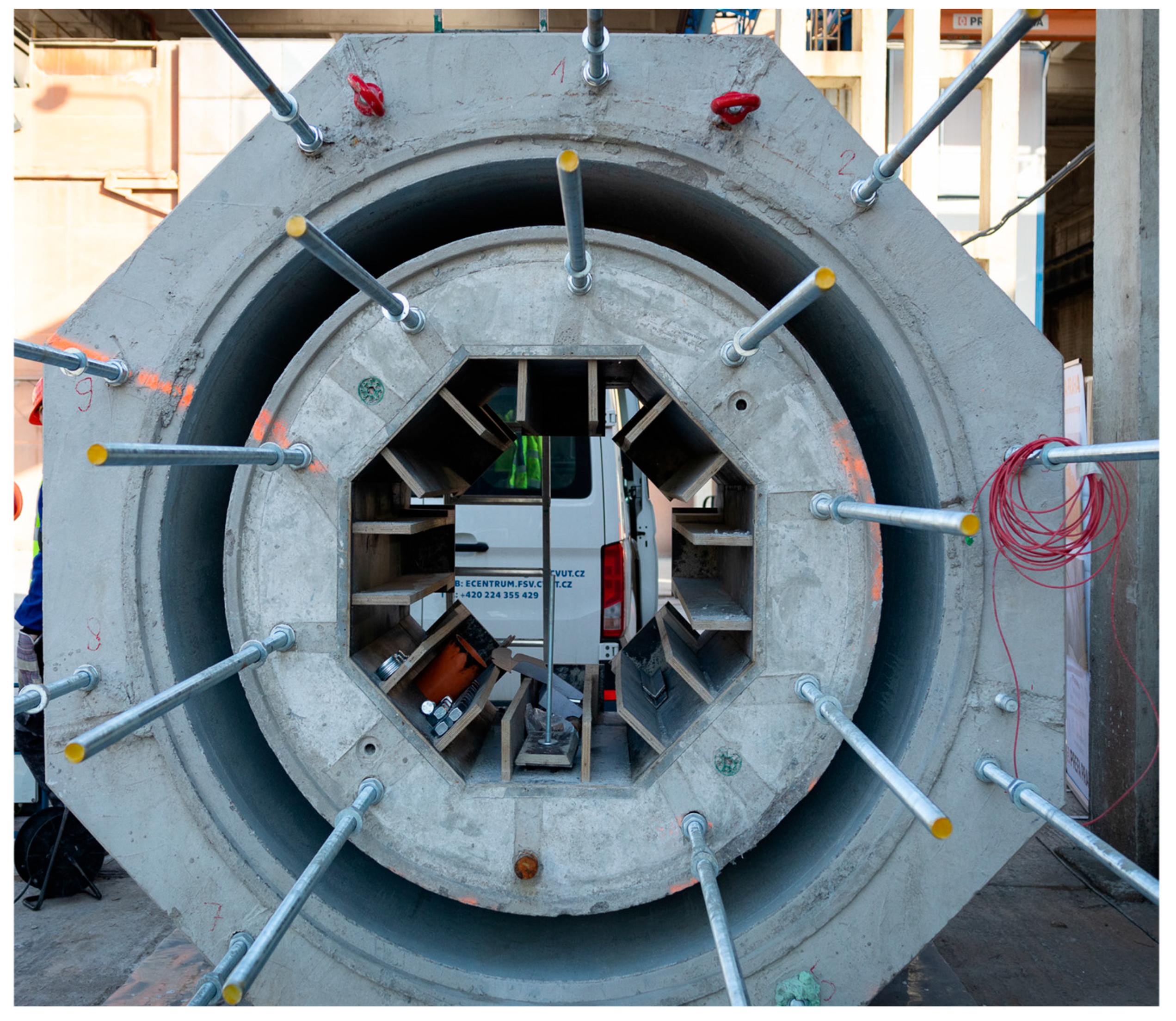
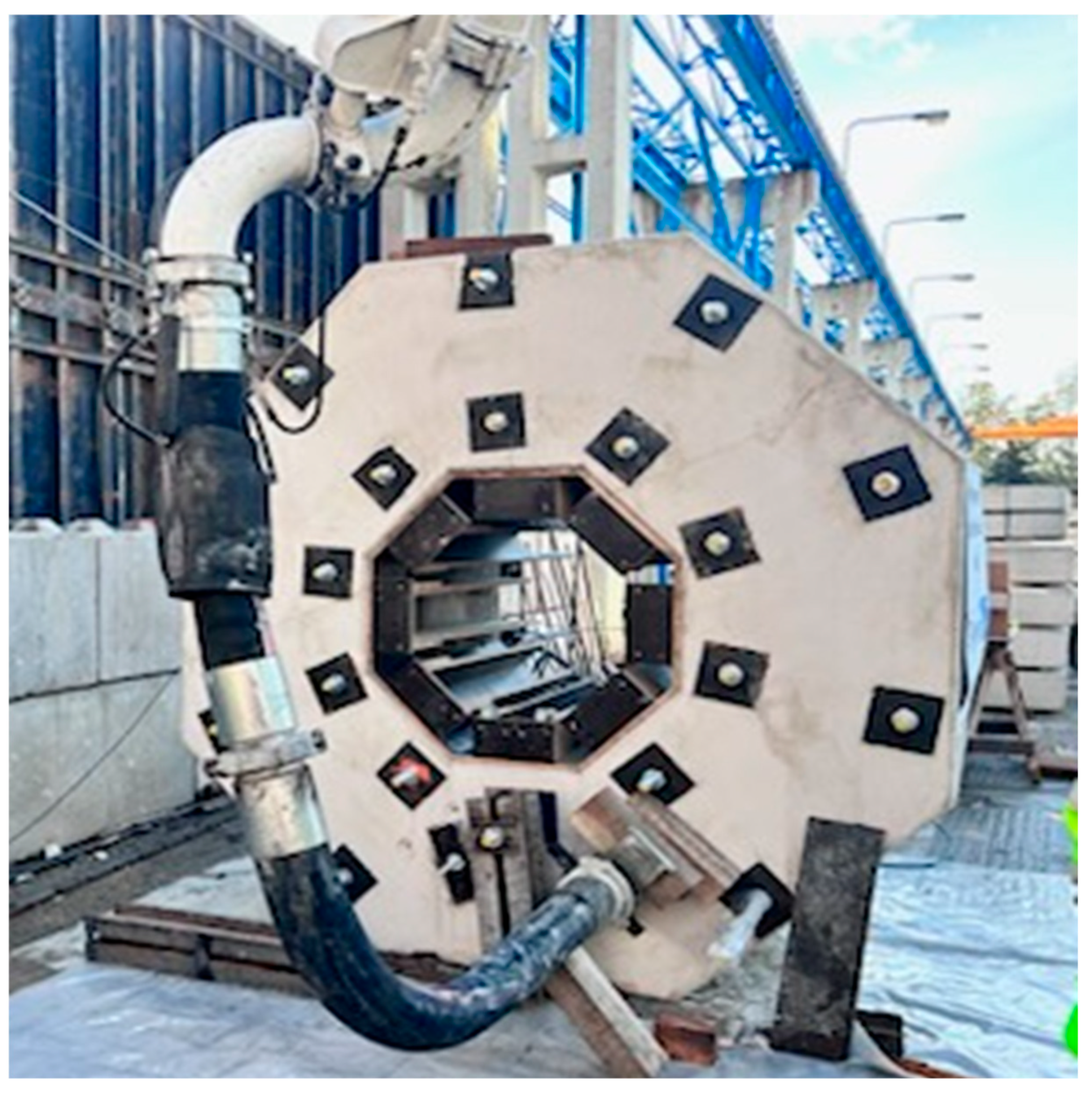
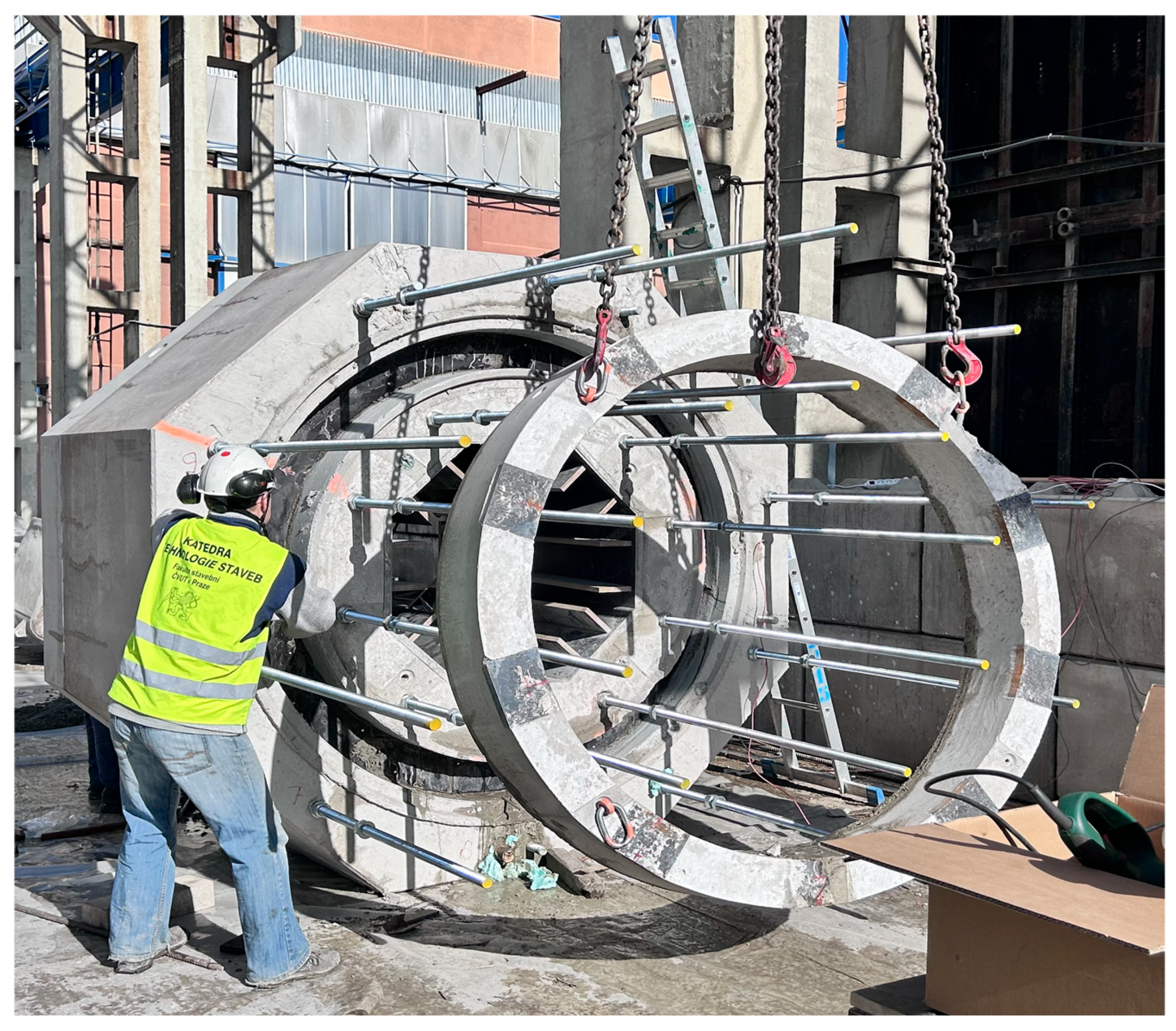
The formwork included an octagonal base, inner and outer concrete rings, and reinforcement anchored into the base, see Figure 4 and Figure 5. The concrete was delivered by a truck mixer, pumped into the structure (Figure 6), and sealed for curing. Sensors monitored deformation and pressure throughout the process.
Testing showed the concrete reached significant stiffness within three hours, with compressive strength values confirming good mechanical performance. Load experiments revealed predictable deformation patterns under varying pressures, closely matching real-world tunnel conditions.
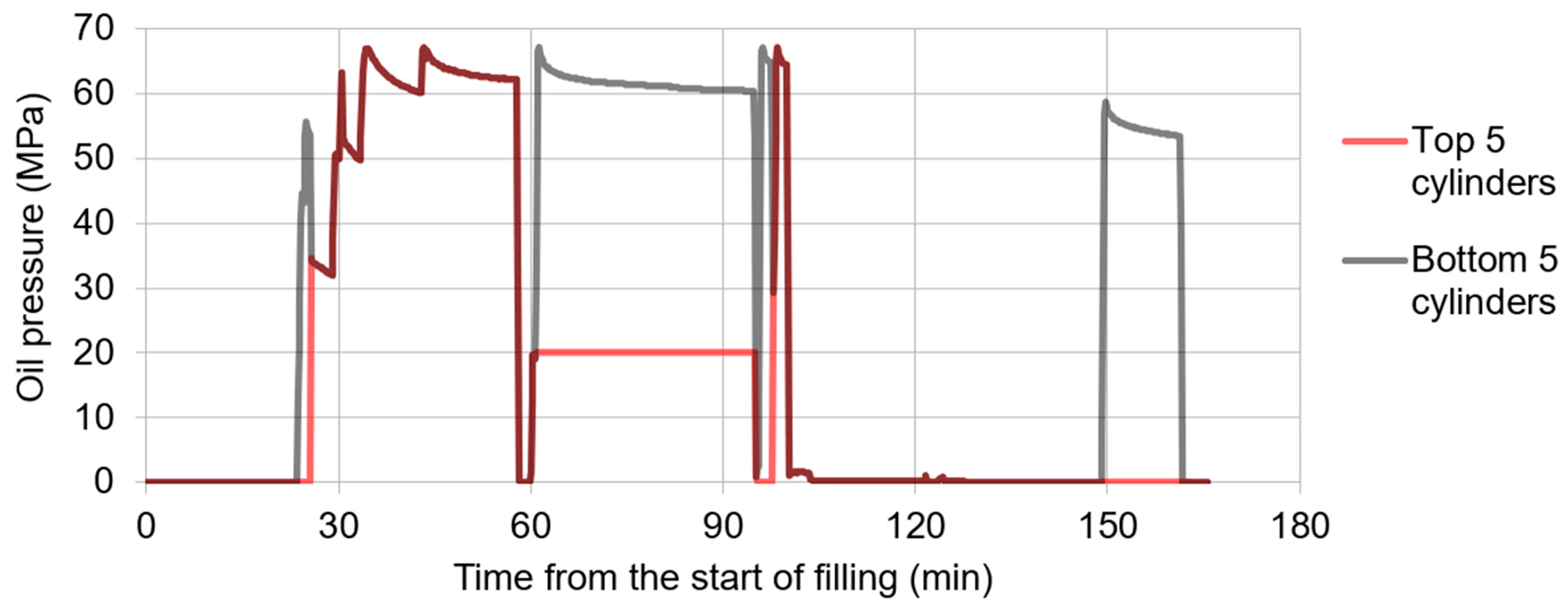
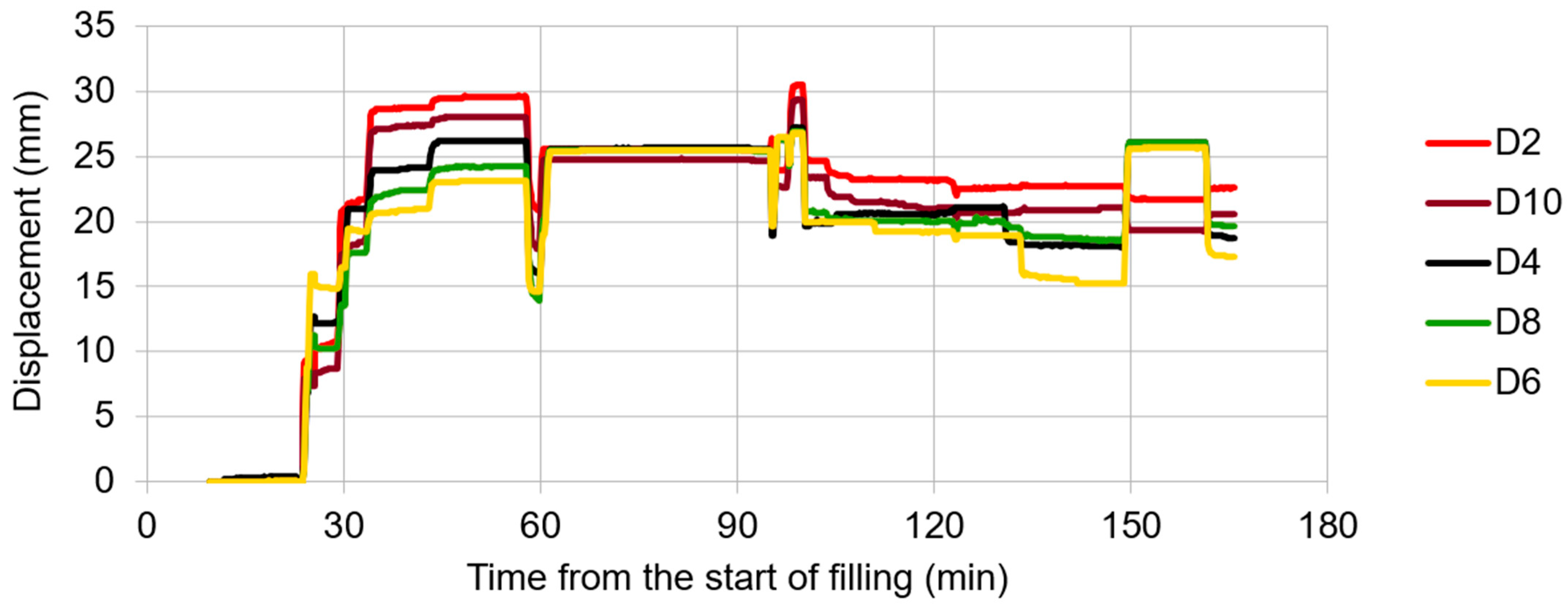
After filling the space with concrete (about 20th min. of the experiment), the concrete plunger was loaded by hydraulic cylinders with the pressure summarized in Figure 7. Excess water was expelled from the concrete mixture (Figure 8). This is characterized by a gradual increase in deformation (Figure 9), when the mixture becomes compacted. It is evident that the sensors located in the upper part of the specimen show greater deformations compared to the sensors in the lower part. This effect can be attributed to the effect of the hydrostatic pressure of the concrete mixture, which acts against the loading cylinders.
Next, the specimen was put into a state of relief, when the pressure from the cylinders was released. A partial reduction in deformations is evident in the deformation graph in Figure 9. At this stage, the concrete mixture is compacted well enough to exhibit cohesion.
After that, another loading was applied at the 60th minute of the experiment, when the displacements of the hydraulic cylinders were equalized by applying load to the bottom cylinders only (Figure 7). Subsequently, the specimen was unloaded, and different deformations of the sensors in the upper and lower parts appeared.
A short loading was applied gradually by all cylinders followed with unloading. The constant unloaded state demonstrates that the deformation does not change until about the 130th min. of the experiment. Then, the reverse displacement of the lower sensors occurred, without any adjustment of the load. This phenomenon can probably be attributed to the spontaneous displacement of the plunger, i.e., overcoming the friction force.
At the 150th minute, pressure was introduced into the lower cylinder assembly, which pushed the plunger inside while the top moved slightly outward. This resulted in elastic deformation of the sample, especially in the lower part, while in the upper part we can observe a negative change in deformation. This again corresponds to the elastic response of the lining sample to eccentric loading, which was confirmed even after unloading.
The experiment simulated a possible method of normal loading of the ring during excavation. It is undoubtedly appropriate to load all cylinders as evenly as possible from the beginning, so that the concrete is compacted and the excess water is expelled. This will fix the shape of the concrete ring so that the expansion joint between the rings is as perpendicular as possible to the tunnel axis. In real operation, the matter will be slightly more complicated because the concrete will be pressed into the surrounding rock with additional resistance. We can therefore expect that the deformations will be slightly larger overall.
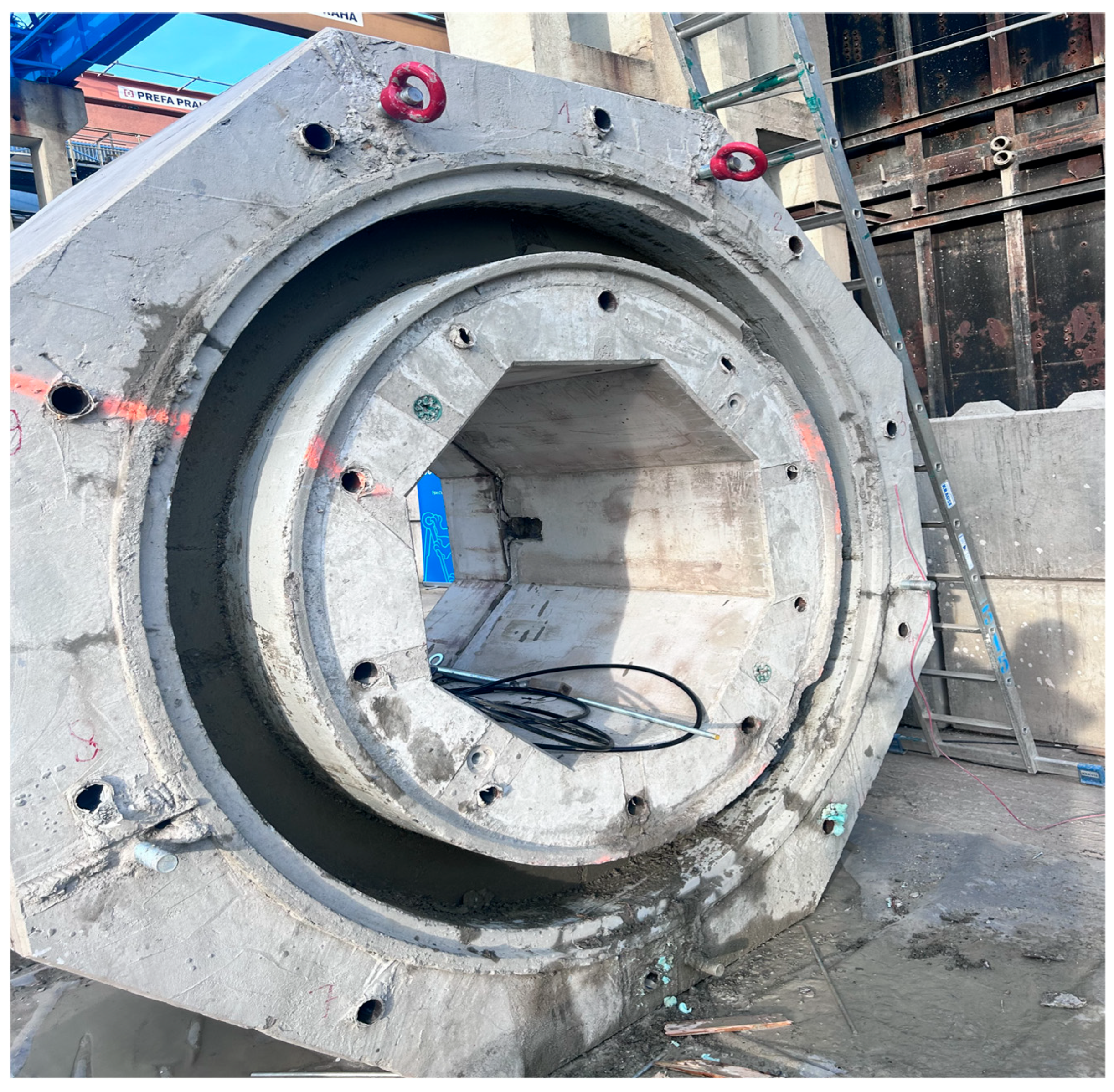
After compaction and expulsion of water, the lining material already shows certain cohesion. The concrete ring already fills the space between the form and the rock, and due to the high pressures, the filling should be of very high quality (Figure 10 and Figure 11). The rock pressure is transferred through the compacted concrete into inner form, and the further pressure of the machine thus creates additional compaction pressure. The experiment has shown that after the concrete has been compacted, it is possible to change the pressure force around the circumference of the plunger and thus control the direction of the machine’s excavation.
Therefore, if the machine reaches a critical stage where it is necessary to change the direction from the beginning of excavation, it is possible to implement the initial pressure without rotating the cutting head, thereby compacting the concrete and then proceeding to excavation with different pressure in the cylinders around the circumference of the ring.
The experiment has also verified that the compacted concrete resists pressure well and, unlike segmental lining, no visible cracks were developed in it from the pressure of the plunger. The experiment has therefore demonstrated the feasibility of the entire technological process of placing, compacting and loading the plunger.
The cast-in-place ring is supported by the inner form until the concrete gains sufficient strength to transfer the rock pressure. This should occur after 16 h from the casting (Table 2). Assuming an excavation speed of 24 m/24 h, a form assembly length of 16 m would be sufficient. With regard to the technology of moving the forms and eliminating risks with possible deviations, the length of the form assembly is assumed to be approximately 20–21 m. The increase in strength is measured without the influence of thermal insulation; when heating the concrete with waste heat from the machine, excavation can be accelerated even further.
Industry experts have confirmed that integrating this cast-in-place system into current TBM operations is both technically and practically feasible.
The main advantages and economic aspects of this method, which was verified by the mock-up experiment, include the following:
  • Absence of precise molds for the production of segments and special halls for reinforcement and concreting prefabricated lining parts.
  • Transportation of the concrete mix in mixer trucks without the need to set up and rent areas for storing segments.
  • Savings on the transportation of segments from the production plant to the construction site.
  • Minimization of joints—saving on seals in the lining, which can be risky both in terms of leaks and stress concentration and related lining failures.
  • Perfect activation of the lining ring with filling of all overcuts created during excavation, with positive impacts on overburden settlement and minimal degradation of the bearing ring around the excavation.
  • In good geotechnical conditions, where shotcrete lining is usually used when tunneling with tunnel boring machines, the use of pressed concrete means obtaining a higher quality structure with zero fall-off, savings, and better use of material.
  • The high ductility of the lining reinforced with dispersed steel fiber reinforcement leads to a reduction in cracks—this saves on renovations.
Like any tunneling method, tunneling using pressed concrete lining has its limitations and special requirements, mainly the following:
  • The need to modify the tunneling machine to accommodate a telescope, temporary waterproofing membrane and formwork for applying the pressed lining.
  • Increased requirements for the scope of geotechnical investigation with a focus on anomalies, which would mean the massive use of accompanying measures to create conditions suitable for excavation.
  • Deployment in geotechnical conditions guarantees the stability of the unsecured face of the excavation for the time necessary to fill the ring space with concrete mix and activate the formwork as a supporting system to ensure the stability of the excavation until the required strength of the cast-in-place tunnel wall is achieved.
  • Hydrogeological conditions with an expected groundwater pressure of up to 5 atm. The expected use of the tunneling method of tunneling machines with a lining of pressed concrete is expected primarily in urban areas, where there is a requirement to minimize the negative effects of excavation on objects in the overburden, i.e., with limited deformation of the rock mass. Another possibility is for tunnels in the extra-urban area, which are designed in a rock environment without major anomalies and a period of stability of the unsecured excavation, where it is possible to use a lining made of pressed concrete without a large range of accompanying measures that could complicate the excavation both in terms of time and in terms of the dimensioning of the lining; this has its limits due to the use of fiber concrete and the constant thickness of the ring.
Figure 4. Geometry of the mock-up experiment: cross-section, cylinder numbers, dimension in mm.
Infrastructures 11 00078 g004
Figure 5. Preparation of formwork for concreting cast-in-place lining.
Infrastructures 11 00078 g005
Figure 6. Pumping concrete into the lining.
Infrastructures 11 00078 g006
Figure 7. Oil pressure on cylinders.
Infrastructures 11 00078 g007
Figure 8. Specimen fitted with hydraulic cylinders.
Infrastructures 11 00078 g008
Figure 9. Displacement between the crossbeam and the ring (zero at filling).
Infrastructures 11 00078 g009
Figure 10. Removal of concrete plunger to check the final condition of the concrete.
Infrastructures 11 00078 g010
Figure 11. The final state of the concrete after 90 min of pumping.
Infrastructures 11 00078 g011
Table 2. Results of compressive strength of concrete.
TimeCylinder Compressive Strength (MPa)
16 h17.2
18 h17.3
1 d24.1
2 d35.2
3 d44.8
7 d55.7
28 d67.3

4. Conclusions

  • Monolithic tunnel lining technology is an innovative advancement in tunnel construction that has been proven feasible for real-world application through full-scale testing. The method involves the insitu casting of a cast-in-place tunnel lining during the excavation process using steel fiber-reinforced concrete, also known as fiber-reinforced concrete. Designed to match the excavation speed of conventional segmental lining systems, it allows construction teams to achieve the same productivity as traditional methods while offering significant environmental advantages. A pressed lining in combination with tunneling using tunnel boring machines is a special application of cast-in-place single-shell lining, which always represents an individual approach in its application.
  • Design of a cast-in-place concrete lining is tied to the possibility of reinforcement using steel fibers only. The choice of lining thickness is based on the possibility of over-dimensioning the lining for the expected most unfavorable condition along the length of the tunnel, increasing or decreasing the bearing capacity of the lining according to the expected, respectively. The actual geotechnical conditions can be achieved in the tunnel route by adjusting the number of fibers or changing the strength class of the concrete.
  • In contrast to segmental lining, concrete pressing creates a homogeneous ring without joints, minimizing the risk of leaks and imperfections associated with the assembly of prefabricated lining segments. The lining is designed to be leak-resistant, which is characterized by stricter conditions for deviation from the designed, theoretical lining thickness than standard cast-in-place linings. This is due to the effort to avoid sudden changes in the thickness of the lining, the associated change in the stiffness of the lining, and the uneven development of hydration heat in the early phase of lining production. In the case of overcuts, they are filled with pressed concrete lining. This is positive from the point of view of activating the lining and minimizing the deformation however can be problematic from the point of view of the formation and development of cracks.
  • Unlike conventional tunneling approaches that require prefabricated concrete segments to be manufactured, stored, and transported to the site, cast-in-place tunnel lining technology produces and installs the lining directly on-site. This reduces transportation requirements, lowers CO2 emissions, minimizes logistical challenges, and significantly decreases the environmental footprint of tunnel construction projects.
  • The feasibility of the system was validated through the mock-up tunnel lining experiment, which demonstrated its ability to pump steel fiber-reinforced concrete efficiently and maintain structural integrity under non-uniform mechanical loading. The test results confirmed that the method can deliver durable, high-performance linings that meet demanding engineering requirements. When integrated with tunnel boring machine (TBM) excavation methods, cast-in-place lining technology offers a practical and competitive alternative to conventional tunneling practices.
  • This approach is suitable for a wide range of underground civil engineering applications, including highway and railway tunnels, metro systems, utility collector tunnels, and subsurface distribution networks. Its combination of high efficiency, structural reliability, and environmental sustainability positions cast-in-place tunnel lining technology as a strong candidate for the future of tunnel construction, providing contractors and infrastructure developers with a faster, greener, and cost-effective solution that is compatible with existing TBM equipment.

Author Contributions

Conceptualization, Š.P., V.Š. and P.V.; methodology, P.H., R.Š., M.V., P.V. and P.R.; software; validation, Š.P., V.Š., M.V., P.V. and P.R.; formal analysis, V.Š. and P.V.; investigation, V.Š. and P.V.; resources, Š.P., R.Š., P.V. and P.R.; data curation, V.Š. and R.Š.; writing—original draft preparation, Š.P. and P.H.; writing—review and editing, Š.P., P.H. and P.V.; visualization, M.V.; supervision, Š.P., P.V. and P.R.; project administration, Š.P., P.V. and P.R.; funding acquisition, Š.P., P.V. and P.R. All authors have read and agreed to the published version of the manuscript.

Funding

The Technology Agency of the Czech Republic (CK03000045).

Data Availability Statement

The raw data supporting the conclusions of this article will be made available by the authors on request.

Acknowledgments

The Technology Agency of the Czech Republic is greatly acknowledged for financing the research under the project CK03000045—Implementation of a new technology of monolithic tunnel lining driven by TBM in civil engineering. Further support from M. Petrtýl, R. Coufal, and the Ministry of Transport of the Czech Republic is also acknowledged.

Conflicts of Interest

Authors Petr Vítek and Pavel Růžička were employed by the company HOCHTIEF CZ a.s. The remaining authors declare that the research was conducted in the absence of any commercial or financial relationships that could be construed as a potential conflict of interest.

References

  1. History of the Prague Metro in Data, DPP, 1969. Available online: https://dpp.cz/metro50/historie-prazskeho-metra-v-datech (accessed on 11 February 2026).
  2. Zapletal, A.; Horejsi, A. Nonlinear Analysis of Concrete Tunnel Liners; Tunel; ITA: Boulogne-Billancourt, France, 2007; pp. 2–7. [Google Scholar]
  3. Noronha, M.; Kochen, R.; Silva, G. Extruded Concrete Lining. Available online: https://library.ita-aites.org/ (accessed on 11 February 2026).
  4. Noguchi, M.; Kanda, H.; Miyazaki, T. Results of a tunneling project using the extruded concrete lining system with shield—Tsugaru-Yomogita Tunnel on the Hokkaido Shinkansen Line. In Proceedings of the World Tunnel Congress (WTC)/39th General Assembly of the International-Tunnelling-and-Underground-Space-Association (ITA), Geneva, Switzerland, 31 May–7 June 2013; pp. 1451–1458. [Google Scholar]
  5. Kimenai, M.C.W.; Hoefsloot, F.J.M. Analysis of extruded concrete lining tunnel by FEM. In Proceedings of the 1st International PLAXIS Symposium on Beyond 2000 in Computational Geotechnics, Amsterdam, The Netherlands, 18 March 1999; pp. 185–196. [Google Scholar]
  6. Babendererde, S.; Babendererde, J.O. Extruded concrete lining—The future lining technology for industrialized tunneling. In Proceedings of the Conference on Rapid Excavation and Tunneling, San Diego, CA, USA, 11 June 2001; p. 7. [Google Scholar]
  7. Ounanian, D.W.; Boyce, J.S.; Maser, K. Development of an extruded tunnel lining system. In Proceedings of the 5th Rapid Excavation and Tunneling Conference, San Francisco, CA, USA, 3 May 1981; pp. 1333–1351. [Google Scholar]
  8. Minemoto, M.; Kito, M.; Kajiwara, Y.; Sasao, H. Design Load of ECL Method Tunnel Lining considering the Creep Characteristic of Ground. J. Jpn. Soc. Eng. Geol. 1995, 36, 203–212. [Google Scholar] [CrossRef] [Scilit]
  9. Boyce, J.S.; Maser, K.R.; Ounanian, D.W. Development of an Extruded Tunnel Lining System; Foster-Miller Associates: John A. Volpe National Transportation Systems Center (U.S.); 1983-12-01 DOT-TSC-UMTA-83-50;UMTA-MA-06-0100-83-6; Urban Mass Transportation Administration: Washington, DC, USA, 1983. [CrossRef]
  10. Doherty, B.J.; Ounanian, D.W.; Maser, K.R. Extruded Tunnel Lining System: Phase 1. Conceptual Design and Feasibility Testing; Technical Report; United States Urban Mass Transportation Administration: Washington, DC, USA, 1979. [CrossRef]
  11. Silva, G.T. Extruded Concrete Lining. In Proceedings of the World Tunnelling Congress Dubai, Dubai, United Arab Emirates, 21 April 2018. [Google Scholar]
  12. Babendererde, S. Underpassing the Rhone and Saone in Lyon, France, with a hydro shield and extruded steel fibre concrete lining. In Proceedings of the Rapid Excavation and Tunnelling Conference, New Orleans, LA, USA, 14 June 1987; Society of Mining Engineers: Littleton, CO, USA, 1987; pp. 611–621. [Google Scholar]
  13. Tatiya, R. Civil Excavations and Tunnelling A Practical Guide, 2nd ed.; ICE Publishing: London, UK, 2017; ISBN 978-0-7277-6153-8. [Google Scholar]
  14. Nasri, V.; Klug, D.; Fulcher, B.; Morrison, J.A. Handbook of Precast Segmental Tunnel Lining Systems; CRC Press: Boca Raton, FL, USA, 2025; ISBN 978-1-032-67553-4. [Google Scholar]
  15. Maidl, B.; Thewes, M.; Maidl, U. Handbook of Tunnel Engineering Volume I: Structures and Methods; Wilhelm Ernst & Sohn, Verlag für Architektur und technische Wissenschaften GmbH & Co., KG: Berlin, Germany, 2013; ISBN 978-3-433-60350-5. [Google Scholar]
  16. Maidl, B.; Thewes, M.; Maidl, U. Handbook of Tunnel Engineering II Basics and Additional Services for Design and Construction; Wilhelm Ernst & Sohn, Verlag für Architektur und technische Wissenschaften GmbH & Co., KG: Berlin, Germany, 2014; ISBN 978-3-433-60354-3. [Google Scholar]
  17. Maidl, B.; Schmid, L.; Ritz, W.; Herrenknecht, M. Hardrock Tunnel Boring Machines; Ernst & Sohn, Verlag für Architektur und technische Wissenschaften GmbH und Co., KG: Berlin, Germany, 2008; ISBN 978-3-433-01676-3. [Google Scholar]
  18. Meschke, G.; Breitenbücher, R.; Freitag, S.; König, M.; Thewes, M. Interaction Modeling in Mechanized Tunneling, 1st ed.; Springer Nature: Cham, Switzerland, 2023; Volume 46, ISBN 978-3-031-24066-9. [Google Scholar]
  19. Maidl, B.; Herrenknecht, M.; Maidl, U.; Wehrmeyer, G. Mechanised Shield Tunnelling, 2nd ed.; Wilhelm Ernst & Sohn, Verlag für Architektur und technische Wissenschaften GmbH & Co., KG: Berlin, Germany, 2012; ISBN 978-3-433-60150-1. [Google Scholar]
  20. Bilgin, N.; Acun, S. Practical Management of Tunneling with Tunnel Boring Machines; CRC Press: Boca Raton, FL, USA, 2024; ISBN 978-1-032-41623-6. [Google Scholar]
  21. Wagner, H.; Schulter, A. Tunnel Boring Machines, Trends in Design and Construction of Mechanized Tunnelling; Taylor & Francis: London, UK, 1996; ISBN 90-5410-811-8. [Google Scholar]
  22. Kolymbas, D. Tunelling and Tunnel Mechanics A Rational Approach to Tunnelling; Springer: Berlin/Heidelberg, Germany, 2005; ISBN 10 3-540-25196-0. [Google Scholar]
  23. DAUB-Working Group. Recommendations for the Selection of Tunnel Borng Machines; Revised Version August 2025; Deutscher Ausschuss für unterirdisches Bauen e. V. (DAUB), German Tunnelling Committee (ITA-AITES): Essen, Germany, 2022. [Google Scholar]
  24. ITAtech AG PFRCS. ITAtech Guidance for Precast Fibre Reinforced Concrete Segments—Vol. 1: Design Aspects; ITAtech Activity Group Support; ITAtech Report N°7, Lausane 04/2016; ITAtech AG PFRCS: Lausanne, Switzerland, 2016; ISBN 978-2-9701013-2-1. [Google Scholar]
  25. ITAtech AG PFRCS. Guideline For Good Practice of Fibre Reinforced Precast Segment—Vol. 2: Production Aspects; ITAtech Activity Group Support; ITAtech Report N°9, Lausane 03/2018; ITAtech AG PFRCS: Lausanne, Switzerland, 2018; ISBN 978-2-9701122-3-5. [Google Scholar]
  26. Wang, X.; Jin, X.; Li, Z.; Zheng, S.; Yao, F. Model Test Study on the Mechanical Characteristics of Boltless Hexagonal Segments in TBM Tunnels. Buildings 2025, 15, 4482. [Google Scholar] [CrossRef] [Scilit]
  27. Wu, L.-M.; Li, H.-K.; Gao, F.; Wang, Z.-J.; Zhang, B.; Luo, W.-J.; Li, J.-J. Experimental Study on Mechanical Differences Between Prefabricated and Cast-In Situ Tunnel Linings Based on a Load-Structure Model. Buildings 2025, 15, 2522. [Google Scholar] [CrossRef] [Scilit]
  28. Yu, S.; Chen, Z.; Li, Y.; Li, W.; Zhang, B. Three-Dimensional Printing Experiments and Particle-Based Meshless Numerical Investigations on the Failure Modes of Tunnel-Lining Structures Containing Fissures. Buildings 2025, 15, 2136. [Google Scholar] [CrossRef] [Scilit]
  29. Su, J.; Jie, Y.; Niu, X.; Liu, C.; Liu, X. Mechanical Behavior of Tunnel Lining with Cracks at Different Positions. Symmetry 2020, 12, 194. [Google Scholar] [CrossRef] [Scilit]
  30. Yang, S.; Wu, Y.; Zhou, Z. Study on the Characteristics of Circumferential and Longitudinal Flow of Vault Concrete during Tunnel Lining Pouring Processes. Materials 2024, 17, 678. [Google Scholar] [CrossRef] [Scilit] [PubMed]
  31. Sorensen, C.; Berge, E.; Nikolaisen, E.B. Investigation of Fiber Distribution in Concrete Batches Discharged from Ready-Mix Truck. Int. J. Concr. Struct. Mater. 2014, 8, 279–287. [Google Scholar] [CrossRef] [Scilit]
Figure 1. The flowchart of the cast-in-place lining construction process.
Infrastructures 11 00078 g001
Figure 2. Scheme of technology.
Infrastructures 11 00078 g002
Figure 3. Three-dimensional model of technology.
Infrastructures 11 00078 g003
Table 1. Parameters of the recipe MOOST_0.
Concrete PropertiesRecipe MOOST 0
CEM I 42.5 R400 kg/m3
Water/cement ratio0.34
Maximum size aggregate Dmax16 mm
ConsistencyS3–S4
Slump160 mm
Disclaimer/Publisher’s Note: The statements, opinions and data contained in all publications are solely those of the individual author(s) and contributor(s) and not of MDPI and/or the editor(s). MDPI and/or the editor(s) disclaim responsibility for any injury to people or property resulting from any ideas, methods, instructions or products referred to in the content.