1. Introduction
Link slab, a short section of a reinforced concrete deck that connects adjacent bridge spans, is proposed to replace traditional bridge joints to enhance the durability of bridges because joint failure caused by bridge deterioration is a frequent issue for bridge maintenance [
1]. The link slab could be either the full or partial depth of the bridge deck to make adjacent bridge decks continuous, but the underneath super-structure stays discontinuous. However, the existing bridge joints replaced by the link slabs may restrict the thermal movements of bridge decks. Upgrading a steel bridge overpassing I-95 with link slabs is a pilot bridge rehabilitation project of the Maryland Transportation Authority (MDTA). The bridge’s total length is 215 feet and 6 inches (65.7 m) and is 34 feet (10.4 m) long in span 1, 76 feet and 3 inches (23.2 m) in spans 2 and 3, and 29 feet (8.8 m) long in span 4. The concrete deck of the bridge has a 7-inch (178-mm) depth and 2-inch (51-mm) overlay. According to the previous finite element analysis conducted for the thermal expansion performance of this bridge, the maximum thermal stress in decks could reach 4.6 times that of existing decks if longitudinal restriction is not released [
1,
2]. To reduce unnecessary and redundant thermal stress, bearing modifications are also proposed to release the longitudinal movements at both ends of the bridge. The demonstration of link slabs with bearing modifications for the bridge is shown in
Figure 1. Fiber-reinforced concrete, including engineered cementitious composite (ECC) and ultra-high-performance concrete (UHPC), were proposed as candidate materials for the link slab to accommodate the bending and thermal expansion in the bridge rehabilitation project. The features of ECC are high ductility and crack control, and the UHPC has high compressive, tensile, and flexural strength. Joints between spans 1 and 2 as well as 2 and 3 are replaced with the ECC link slab; joints between spans 3 and 4 are replaced with a UHPC link slab. To compare and evaluate the material durability of the two types of fiber-reinforced concrete, long-term monitoring was conducted to measure the deformation of the link slabs. The thermal movements of the bridge with bearing modifications and the thermal expansion of the fiber-reinforced concrete link slabs were analyzed in this paper. Although thermal effects are a big factor in employing link slabs, the development history of ECC material and UHPC with follow-up research, and studies on link slab thermal behavior are scarce [
3,
4]. Under a full thermal cycle with positive and negative gradients, there is a potential for full-depth cracking [
5]. The lack of long-term performance data for ECC/UHPC link slabs under modified bearings makes this report unique for filling the research gap on link slab thermal movement. In their FHWA case study report, Thorkildsen et al. (2020) cited a unique Maryland experience in modifying the fixed bearing to slotted hole bearings, as performed in this study [
6]. In their TRR paper, Gergess et al. (2020) described the elastomeric bearing effect on the structural behavior of bonded link slabs [
7]. Recent research has investigated the thermal conductivity and thermal behavior of engineered cementitious composites (ECCs) with different mixtures [
8,
9].
2. Field Monitoring Design and Installation
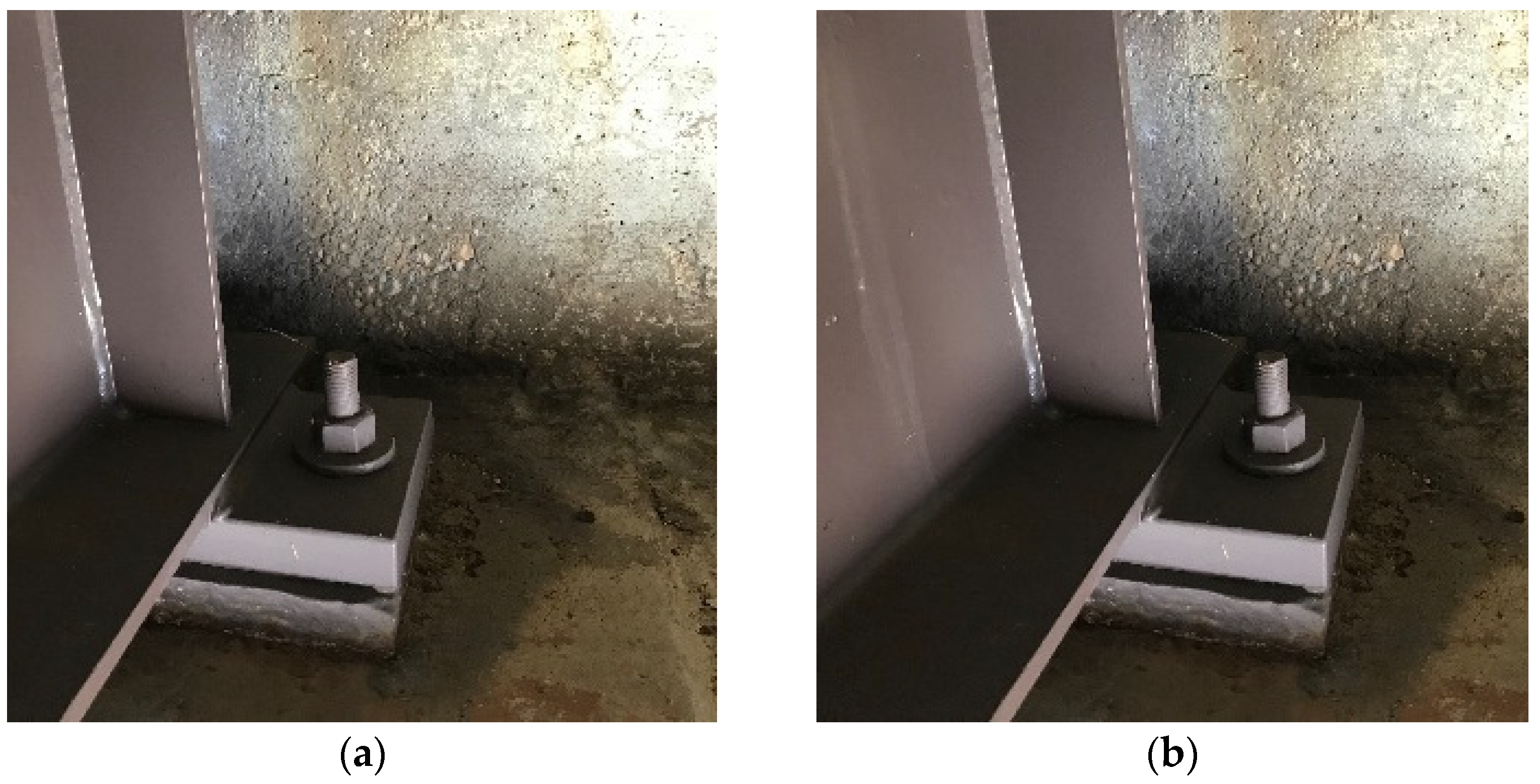
The existing fixed bearings at the bridge ends were modified to expansion bearings, as shown in
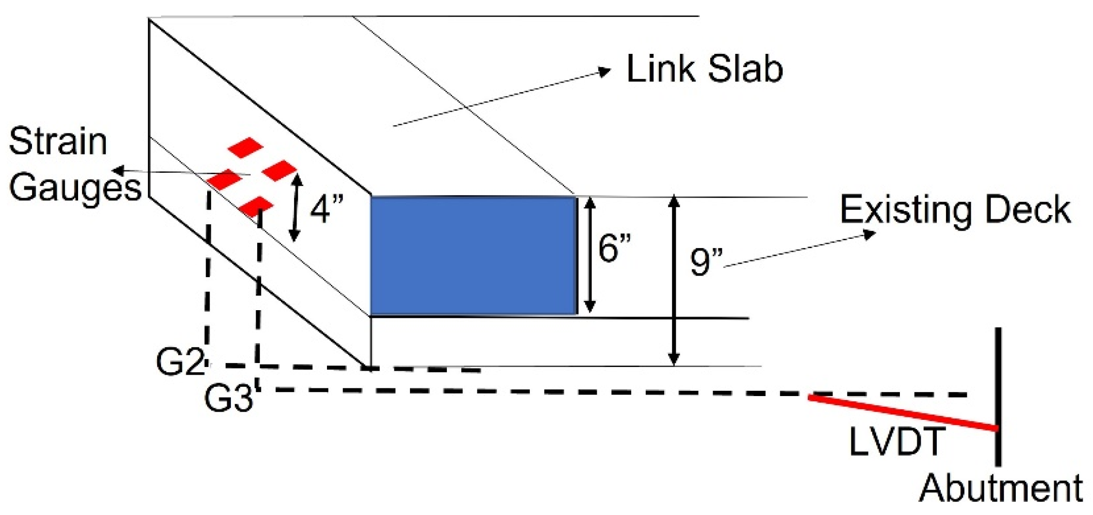
Figure 2a,b. To validate the girder movement with modified bearings, linear variable differential transformers (LVDTs) were installed at the third girders, connecting the girder ends and abutments to detect their relative displacement, as shown in
Figure 3a. The resolution of LVDT was 0.01 mm, and its measurement range was 50 mm. When the temperature rises, the thermal expansion of the girder compresses the LVDT and decreases the LVDT measurement. In contrast, when the temperature falls, the measurement of LVDT increases. The special-made strain gauge sets were developed to be embedded into the link slab to detect the deformation, as shown in
Figure 3b. The resolution of the strain gauge was 1 micro-strain (μm), and its measurement range was ±4000 μm. The custom-made strain gauge set contained four strain gauges that are separated into two side-by-side pairs and four-inch-high double layers. The strain gauges were connected with the transmitters underneath the bridge deck near piers, as shown in
Figure 3. The strain gauges were located at the bottom of the link slab and two inches below the bridge surface. The location of the strain gauge sets were at the second girder and third girder. The sensor arrangement of the strain gauge is shown in
Figure 4. During the 18 months of monitoring (20 December 2019–30 June 2021), one LVDT sensor for the UHPC link slab side girder’s movement was disconnected for 50 days due to water leakage in the connected wireless transmitter. The girders’ movements were mainly induced by temperature variation. The temperature origin for both sides was approximately 49 °F, which was the environmental temperature of sensor installation as well as the initial temperature of long-term monitoring.
3. Girder Movement with Link Slab Under Thermal Expansion
The longitudinal deformation of link slabs is subject to thermal movement of bridge girders, which is opposite to regular thermal expansion. The girders’ movements could be divided into contraction and expansion stages. In the contraction stage, girders start to contract when the environmental temperature is below the initial temperature. Meanwhile, the link slab is under tensile conditions between adjacent decks because it tends to accommodate increasing gaps. In the expansion stage, girders start to expand to compress the link slab when the environmental temperature becomes higher than the initial temperature [
10]. Therefore, the link slab is under compressive conditions due to the narrowing of the gap. The girder movement time series of the UHPC side and ECC side are shown in
Figure 5. Analytical thermal expansion was estimated by the AASHTO LRFD Bridge Design Specifications, which is 6.5 × 10
−6 × L
span × Temp
diff for steel material [
11]. The movement of UHPC side and ECC side girders compared with analytical estimation in the contraction and expansion stages are summarized in
Table 1. When the temperature started to exceed the initial temperature (49 °F), the expansion movement of the ECC side girder was less than that of the UHPC side by 5.6 mm and 40% less than that obtained by the analytical method. The contraction movement of ECC side girders at a temperature below 49 °F was close to that of UHPC side girders. Both expansion and contraction movements of the UHPC side girder were 25% more than the analytical estimation. It could be assumed that the bearing modification on the UHPC side was fully released and that the UHPC link slab could transfer the thermal movement of the steel girders completely. Although following the same trend, the thermal movement of the ECC side girders was less than the analytical estimation in either expansion or contraction conditions. There are two possible reasons that made movement on the ECC side lower than that in the analytical estimation. First, the movement might be curbed by construction defects toward the abutment, which is comprised of external cover plates with a bearing modification. Some cover plates had insufficient room for bearing plate movement, and it was found that the bearing plates fully contact the cover plates. The allowable sliding room of bearings on the ECC side was smaller than that on the UHPC side. The second reason is that the stiffness of ECC material was much lower than that of UHPC, and the ECC link slab might absorb movement from the girders and become ductile rather than transmitting thermal movement toward the abutment [
10,
12].
4. Link Slab Performance with Temperature Variation
In the field construction, Elephant Armor DOT (EA DOT) was selected as the main source of ECC, which is a pre-packaged and ready-mixed commercial concrete product with polyfiber. Additionally, Ductal JS1000 was the major cementitious material with steel fiber used as UHPC. The tensile strength, compressive strength, and flexure strength of Elephant Armor DOT and Ductal JS1000 were tested in prior laboratory construction and are listed in
Table 2 [
13]. In addition to flexural deformation caused by a live load, it is critical to link slab durability to environmental temperature variation, as it induces longitudinal strain fluctuation continuously. For the link slab, the continuous strain variation is mainly controlled by the thermal movements of girders. The link slab is under a compression state when the temperature rises. In contrast, the link slab is under a tensile state when the temperature falls. The conceptual interaction between girder movement and deformation is illustrated in
Figure 6. Strain data of ECC and UHPC link slabs in the top layer of girder monitored for 18 months 3 were selected, and the results are shown in
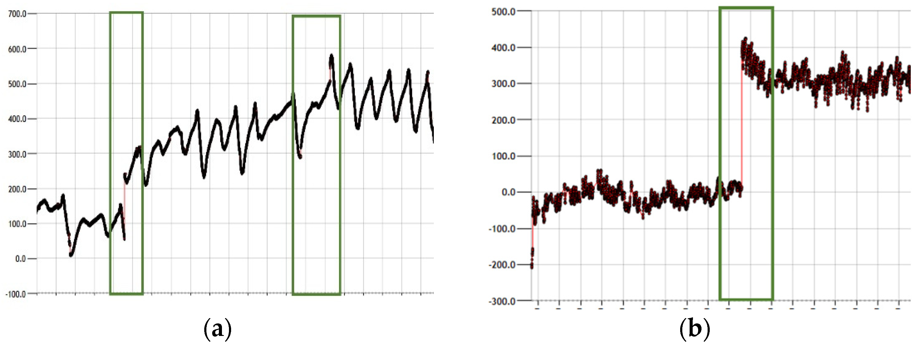
Figure 7a,b. Some minor surface cracks were found on the UHPC surface due to shrinkage in its early stage. The sensors detected 200–400 μm shrinkage in the first few days, and it was within an allowable deformation range. After the early shrinkage stage, no large crack was detected in the UHPC. The surface cracks in the ECC link slab were hardly visible during the monitoring period. However, three large strain increments were detected in the top layers of girders 2 and 3. For the strain gauge in the top layer of ECC girder 3, the link slab’s total strain increased by 200 μm, including 170 and 70 μm increments, as shown in
Figure 8a. For the strain gauge in the top layer of ECC girder 2, the ECC link slab’s total strain increased by 350 μm, primarily from one 300 μm increment, as shown in
Figure 8b. The large strain increments were detected 60 days after construction, and they could be formed by tiny cracks near strain gauges. The ratio of strain variation and temperature variation stay consistent after strain jump. According to EA DOT material tests in the laboratory, the strain increment scale did not exceed the allowable flexural deformation, which is 400 μm [
6]. ECC link slab performance after relatively large strain increment occurrences is essential for validating the ECC link slab’s durability. Based on the monitoring data, the ECC link slab still worked along with temperature variation changes and remained stable after large strain increments. It could be inferred that the large strain increments were formed by multiple tight cracks with control rather than a single major crack. Therefore, it could be assumed that the performance of the ECC link slab entered a relatively ductile stage.
5. Link Slab Deformation and Girder Movement Interaction
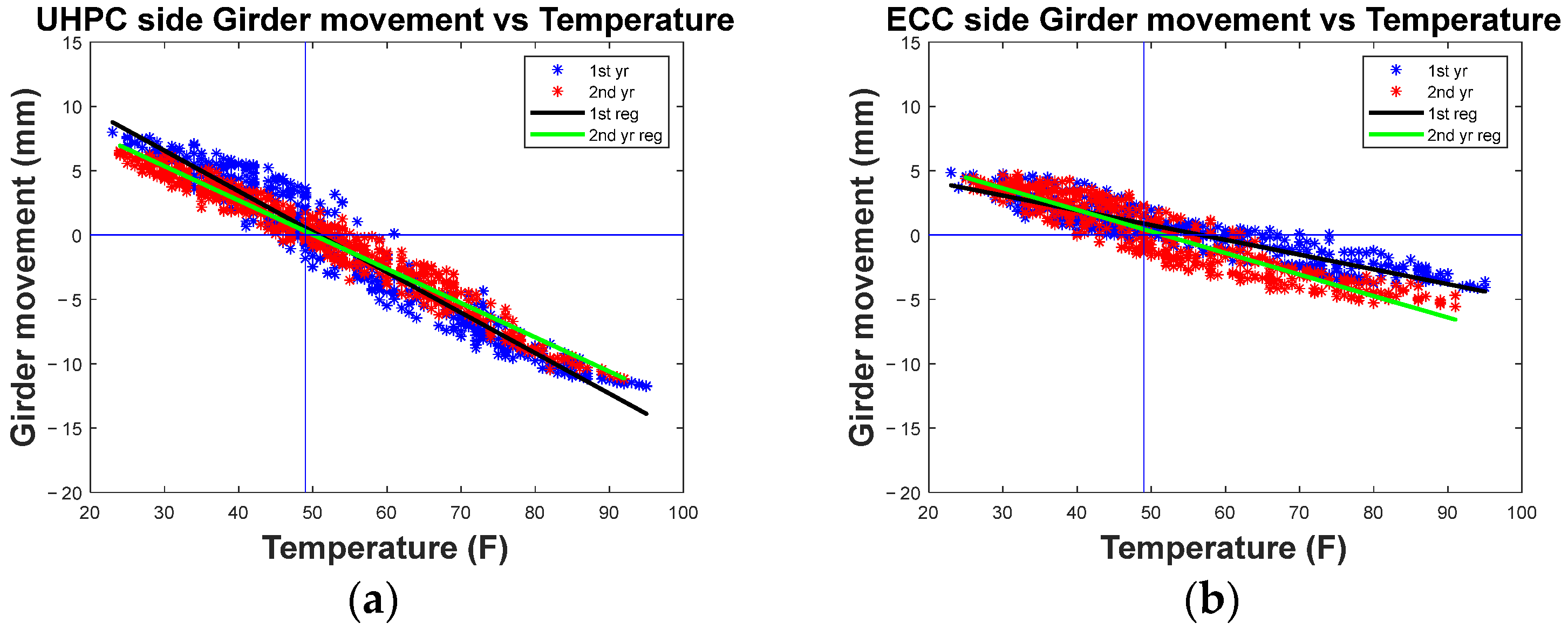
The long-term monitoring data of link slab deformation, girder movement, and environmental temperature were used to investigate the interaction relationship between link slabs and thermal movement and to validate the structural performance of existing bearing modifications. The first case analysis of the interaction relationships between girder movement and temperature on the UHPC side and ECC side, respectively, are shown in
Figure 9a,b. The girder movement measurement on the UHPC side performed linearly with the environmental temperature. The slope of the second-year regression had a slight difference from the first-year regression line and a higher correlation coefficient, which shows that the girder movement was highly dependent on the environmental temperature after the first contraction and expansion cycle with accommodation. The interaction relationship between ECC side girder movement and temperature was linear but more dispersed than that of the UHPC side. The correlation coefficient of the second year became higher than the first year’s correlation coefficient, which is similar to what was observed for UHPC. In conclusion, the girder movements on the ECC side and UHPC side performed linearly with variations in temperature. The linear regression model of the UHPC side represents a nearly complete thermal movement effect, but the regression model of the ECC side merely covered 50% of the thermal effect moving range.
The second case analysis of strain variation of UHPC and ECC link slabs compared with the temperature are shown in
Figure 10a,b. For the UHPC link slab, the deformation varied along with temperature consistently and linearly. A slight strain difference occurred between the first year and second year regression lines, and the overall decrease in strain was close to the initial shrinkage. The monitoring data for the second year was more condensed, and the regression line was flatter than the line of the first year. It is assumed that the UHPC material enters a steady state after the first-year tension and compression cycle. For ECC material performance, after a significant strain increment occurred, the strain variation of ECC performed linearly with environmental temperature. The regression line passing through the initial temperature (49 °F) was about 250 μm higher than the initial origin, which is close to the summation of large strain increments shown in
Figure 8a.
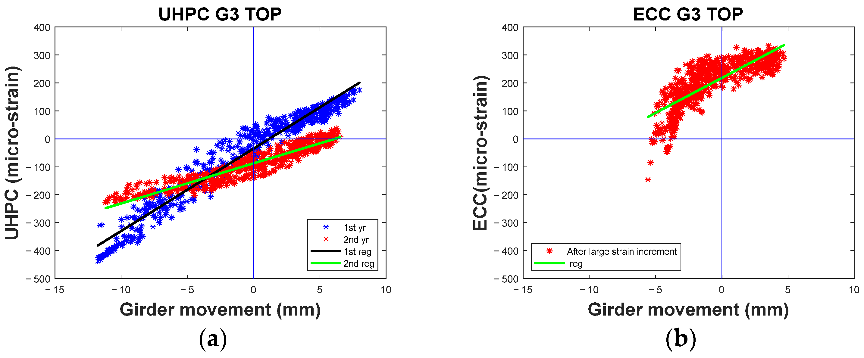
The purpose of the third case analysis is to eliminate the factor of environmental temperature by comparing deformations of the UHPC and ECC link slabs with the girder movement, as shown in
Figure 11a,b. It showed that the interaction relationship between girder movement and UHPC link slab strain variation was also highly linear. Unlike the relationship between displacement and temperature or strain and temperature, the correlation coefficient of the second year was lower than the first year. The correlation coefficient of the ECC link slab was 0.817, which was much lower than other linear regression. Therefore, the linear relationship was less accurate for representing ECC link slab deformation with girder movement. The detailed linear regression parameters of displacement and temperature, strain and temperature, and strain and displacement are summarized in
Table 3 and
Table 4.
The linear regression model is assumed to represent the interactions of link slab deformation, environmental temperature, and girder movement. The coefficient of determination (R
2), representing the percentage of the variation in the dependent variable explained by variations in the predictor and the ratio between the standard error of the estimate and the standard deviation of the criterion variable (S
e/S
y), is the factor validating whether two variables have a linear relationship. The suggested excellent rating parameters for fitting are R
2 > 0.89 and S
e/S
y < 0.35. On the secondary level, the good rating parameters are 0.7 < R
2 < 0.89 and 0.36 < S
e/S
y < 0.55 [
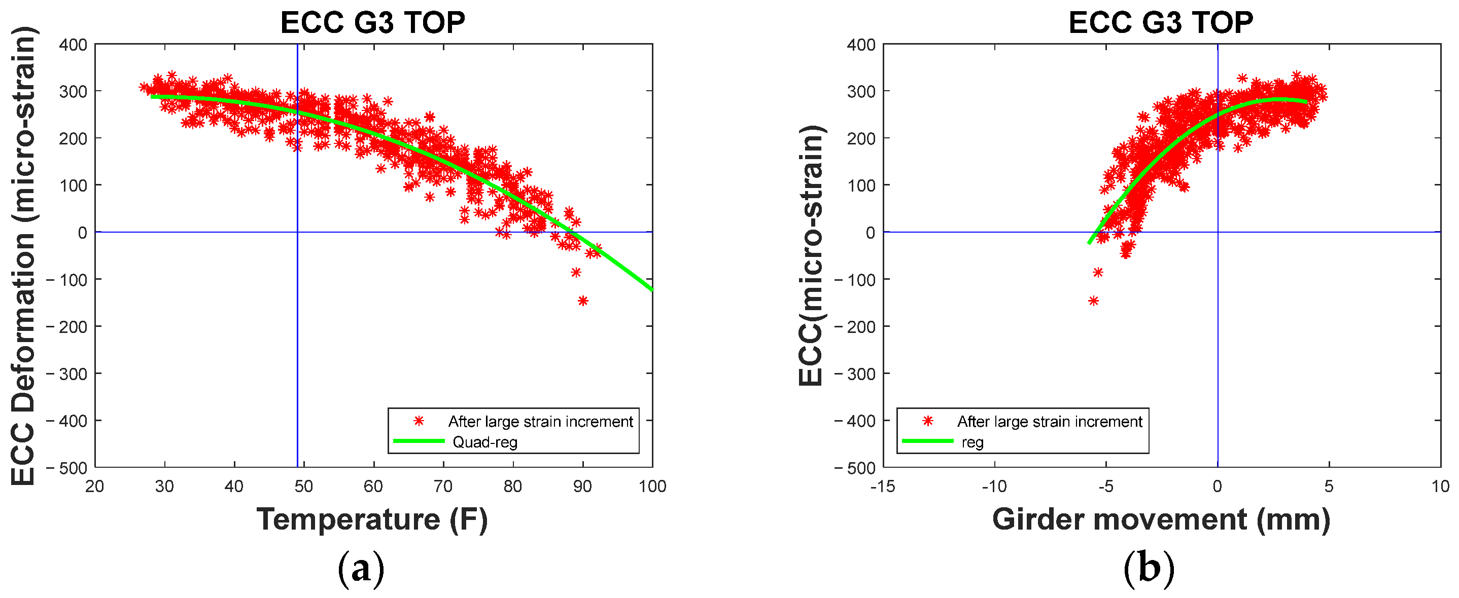
3]. The linear relationships of girder movement vs. temperature, strain vs. temperature, and first year of strain vs. girder movement for UHPC were rated as excellent fitting. Girder movement vs. temperature, strain vs. temperature for ECC, and second year of strain vs. girder movement for UHPC were rated as good fitting. Since the deformation of the ECC link slab and girder movement on the ECC side tended to disperse non-linearly, the second-order quadratic regression was selected to fit the deformation of ECC and temperature as well as deformation of ECC and girder movement, as shown in
Figure 12a,b. It is believed that quadratic regression could fit the two ends of the distribution, making the possible extreme conditions more accurate.
6. Conclusions
In this study, the long-term monitoring data of fiber-reinforced concrete deformation and girder movement are used to analyze the thermal effect on structural performance of UHPC and ECC link slabs subjected to girder movement with a bearing modification. It was concluded that
A. UHPC link slab:
(1) The bearing modification enabled UHPC link slabs to have 25% more room for movement in either the expansion or contraction direction than the analytical estimation.
(2) The girder movement on the UHPC link slab side and the deformation of the UHPC link slab had a highly linear relationship with environmental temperature.
(3) Under the conditions of consistent girder movement, it is assumed that girder movement measurement could be used to ensure the structural performance of the UHPC link slab.
B. ECC link slab:
(4) There was only half of the analytical movement for girders to move on the ECC link slab side, and the expansion direction was mainly limited.
(5) Though the girder movement on the ECC link slab side was restricted, the girder movement measurement still maintained a strong linear relationship with environmental temperature. The ECC link slab is believed to have a significant strain increment (250 μm) within the first five months according to the strain vs temperature regression figure.
(6) After large strain increment, the ECC link slab had a less strong linear relationship with temperature and girder movement than the UHPC link slab. It is believed that the ECC material will be ductile after the formation of continuous minor cracks. With large and non-reversible deformation, the ECC link slab performed more non-linearly; nevertheless, visible surface cracks were hardly discovered on the ECC link slab.
C. Overall:
(7) In summary, the existing bearings were successfully released by modification, and the effect ranged from 50% to 150% of the analytical estimation. The UHPC link slab performed stably and consistently with girder movement and temperature variation. The ECC link slab became ductile with girder movement, and the fine cracks in the link slab were detected by a special-made strain gauge.
(8) In general, visible surface cracks were not found in the first 18 months and the measurement tended to be stable in link slab deformation and girder movement.
(9) Therefore, the fiber-reinforced concrete link slab with bearing modifications was proven as a durable and cost-efficient application for reducing joint failure risk and extending the bridge service life.
In conclusion, the major findings of this research are listed in items 7–9. By numerical simulations, the same conclusion can be reached for straight two to four medium span bridges, which are a common type of overcrossing bridge for the MDTA toll road. Future research can be extended to skewed or curved with different UHPC and/or ECC materials.

