Article

Comprehensive Substantiation of the Impact of Pre-Support Technology on a 50-Year-Old Subway Station During the Construction of Undercrossing Tunnel Lines

by
Bin Zhang
,
Shaohui He
*,
Jianfei Ma
,
Jiaxin He
,
Yiming Li
and
Jinlei Zheng
School of Civil Engineering, Beijing Jiaotong University, Beijing 100044, China
*
Author to whom correspondence should be addressed.
Infrastructures 2025, 10(7), 183; https://doi.org/10.3390/infrastructures10070183
Submission received: 17 June 2025 / Revised: 8 July 2025 / Accepted: 9 July 2025 / Published: 11 July 2025
(This article belongs to the Special Issue Recent Advances in Railway Engineering)

Abstract

Due to the long operation period of Beijing Metro Line 2 and the complex surrounding building environment, this paper comprehensively studied the mechanical properties of new tunnels using close-fitting undercrossing based on pre-support technology. To control structural deformation caused by the expansion project, methods such as laboratory tests, numerical simulation, and field tests were adopted to systematically analyze the tunnel mechanics during the undercrossing of existing metro lines. First, field tests were carried out on the existing Line 2 and Line 3 tunnels during the construction period. It was found that the close-fitting construction based on pre-support technology caused small deformation displacement in the subway tunnels, with little impact on the smoothness of the existing subway rail surface. The fluctuation range was −1 to 1 mm, ensuring the safety of existing subway operations. Then, a refined finite difference model for the close-fitting undercrossing construction process based on pre-support technology was established, and a series of field and laboratory tests were conducted to obtain calculation parameters. The reliability of the numerical model was verified by comparing the monitored deformation of existing structures with the simulated structural forces and deformations. The influence of construction methods on the settlement changes of existing line tracks, structures, and deformation joints was discussed. The research results show that this construction method effectively controls the settlement deformation of existing lines. The settlement deformation of existing lines is controlled within 1~3 cm. The deformation stress of the existing lines is within the concrete strength range of the existing structure, and the tensile stress is less than 3 MPa. The maximum settlement and maximum tensile stress of the station in the pre-support jacking scheme are −5.27 mm and 2.29 MPa. The construction scheme with pre-support can more significantly control structural deformation, reduce stress variations in existing line structures, and minimize damage to concrete structures. Based on the monitoring data and simulation results, some optimization measures were proposed.

1. Introduction

Over the past decade, with the acceleration of urbanization, public transport infrastructure has also entered a period of rapid development [1,2,3]. With the rapid growth of the urban population, the pressure on urban infrastructure and transportation systems has also increased [4,5,6,7].
Underground rail transit is an effective solution to alleviate ground traffic pressure [8,9,10]. As a major player in urban transportation, the subway has seen its network grow increasingly dense and complex with the rapid expansion of urban rail transit networks. Many newly constructed underground projects have to interact with existing subway tunnels. It is necessary to prevent construction from affecting the operation of existing lines and reduce the negative impact of new constructions on existing underground structures [11,12,13,14,15,16,17].
More literature has discussed the influence of underground excavation on existing tunnels and protection measures, leading to the emergence of various construction methods, which increase the construction difficulty of new projects [18,19,20]. When a newly built subway station crosses an existing tunnel, it causes the greatest disturbance to the existing tunnel. In the construction process of the new tunnel, it is very important to study the process of the new tunnel crossing the existing line to ensure the safety, stability, and durability of the existing line and the new line [21,22,23,24]. Commonly adopted methods, such as numerical simulation, field monitoring, model experiments, and theoretical analysis, are used to study the deformation characteristics of existing lines during the undercrossing process. This further explores the influence mechanism of different tunnel support and excavation methods on deformation control, aiming to seek optimal solutions [22,23,25,26]. Therefore, it is necessary to study the different mechanical behaviors of various existing lines caused by different undercrossing construction methods [25,27,28,29,30,31,32].
The differences between different construction methods mainly lie in the control methods for the disturbance caused by the new tunnel undercrossing existing lines. Cases of undercrossing tunnel lines mainly focus on close-proximity vertical (above/below) or oblique crossing of existing tunnel lines, usually adopting grouting and structural support methods to control the settlement of existing lines [33,34,35,36,37,38,39,40]. Li et al. [25] combined composite pre-reinforcement technology with shallow buried and underneath excavation methods to control the deformation of existing large-diameter tunnels and reduce their impact on them. Wei et al. [26] studied the shield tunneling undercrossing of existing metro tunnels, using pipe-roof pre-reinforcement to stabilize the soil between the existing tunnels and the new shield tunnel, and explored the deformation characteristics of the existing tunnels during the double-shield undercrossing process. Zhou et al. [30] proposed three innovative construction schemes for the zero-distance undercrossing of existing tunnels by new metro stations and explored the deformation control mechanisms of different schemes through numerical simulations.
Due to the structural and construction environmental characteristics of subway projects, the method combining field monitoring and numerical simulation is typically used to study the rationality of construction methods for underground engineering [41,42,43,44]. Using the method of numerical simulation, different construction methods are designed for various subway engineering construction environments [45,46,47]. Nan Liu et al. [45] established a stratum-structure numerical finite element model based on field-measured data to study the influence of various process conversions during PBA station construction on surface settlement and the stress of station support structures. Jianbing Lv et al. [48] studied the mechanical response of steel pipe piles in pile–soil interaction under the pile–beam–arch (PBA) method by comparing numerical simulation with field monitoring data of surface settlement. Yinchuan Qi et al. [49] adopted the Mohr–Coulomb model and elastic model, respectively, and used FLAC3D to study the super large deep foundation pits on both sides of the existing subway, analyzing the deformation of the foundation pits and their surrounding environments. Zhijian Jiang et al. [50] studied the influence of deep foundation pit excavation on the deformation of adjacent buildings and established a three-dimensional numerical model of the foundation pit, existing subway stations, and tunnel structures using FLAC3D 6.0 software. Weiqiang Qi et al. [51] adopted FLAC3D software and combined it with field monitoring to study the deformation of existing tunnel structures caused by excavation. This paper combines numerical simulation with field monitoring and uses laboratory tests to provide material parameters for the station model, aiming to study the impact of the construction method proposed in this paper on the subway station.
This project is based on the construction of Beijing’s new Subway Line 3 under the existing Subway Line 2 Dongsi Shitiao station (Figure 1). Because the existing Subway Line 2 has a long history of operation and is in operation, it is necessary to minimize the settlement of the existing Subway Line 2 caused by the underpass construction. There are many existing buildings around, and the soil settlement caused by construction needs to be strictly controlled. Due to the structural aging and historical defects in the long-term operation of the subway, it is very important to evaluate and control the risk of the underpass project.
To solve these problems, a single-span underground station construction method based on the pre-supporting technology of the pile–beam–arch method is proposed. As a common construction method of subway tunnels, the pile–beam–arch (PBA) method can form an effective supporting structure in the early stage of excavation and reduce the disturbance of soil during construction [52].
In this paper, the arch–beam–pile foundation structure in the PBA method is changed to the straight wall arch–beam–pile foundation structure scheme. The vault is pre-supported by the connection of jacks and piles to control the station structure and stratum deformation caused by construction. In addition, the middle pilot tunnel construction method is also pre-supported by jacks, which greatly reduces the settlement of the existing Line 2 station. By forming a close lining, the soil loosening caused by excavation in the weak stratum is solved, and the change of soil bearing capacity and settlement of the existing station is reduced. At present, the construction scheme mainly increases the bearing capacity through soil grouting or soil support to control the deformation of the existing subway structure [24,30,47,53]. This method has the advantages of timely support, high efficiency, and good settlement control effect [9,52,54].
So far, few studies have focused on the application of the PBA method in the construction of the subway station. This work studies the construction process through numerical simulation and on-site monitoring, providing a research reference and another potential option.

2. Research Background

Dongsi Shitiao Station is one of the first-generation subway stations in China. The station structure has been in operation for 50 years and remains in service, so special construction methods must be adopted to minimize the disturbance of the construction to the station structure.

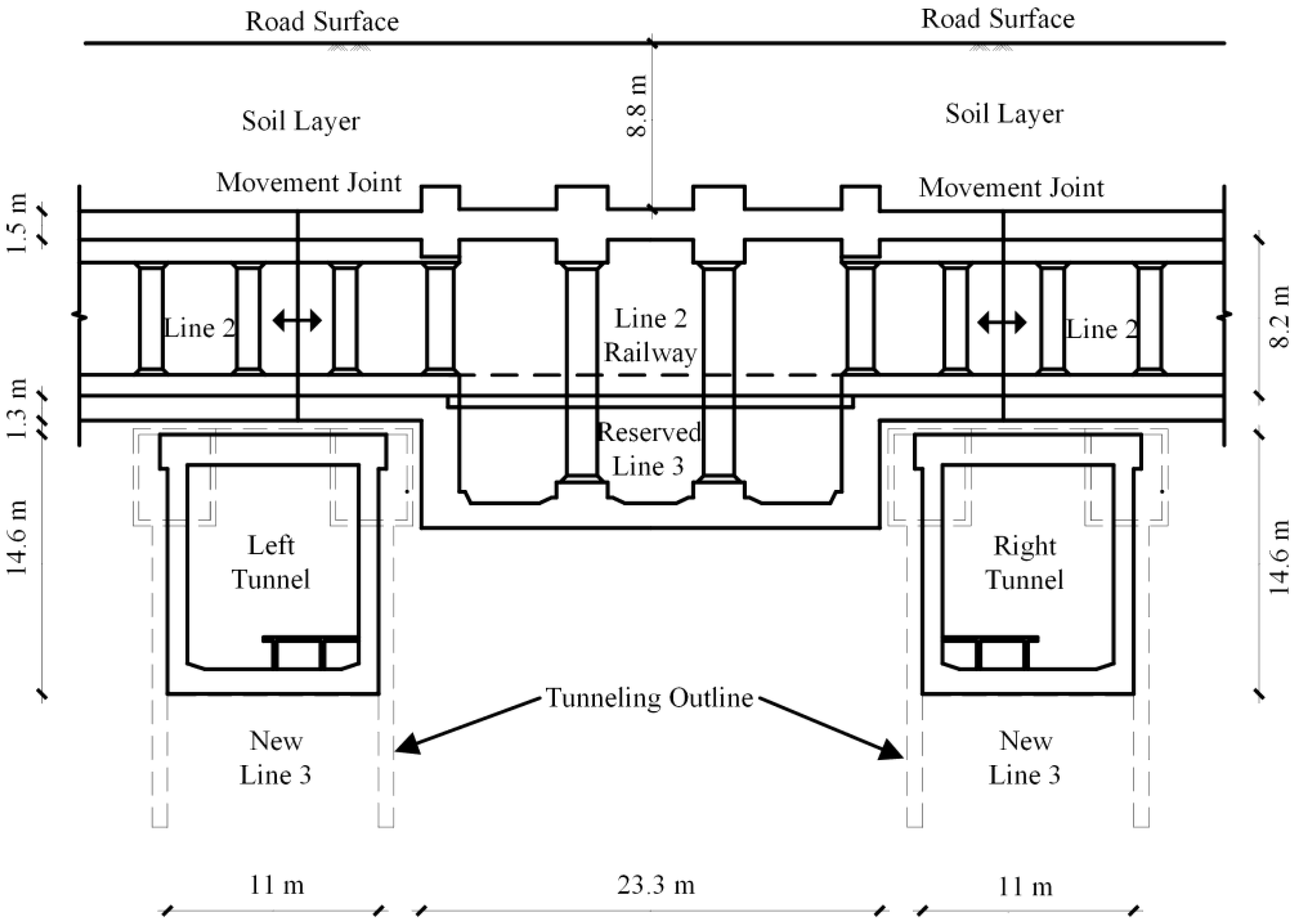
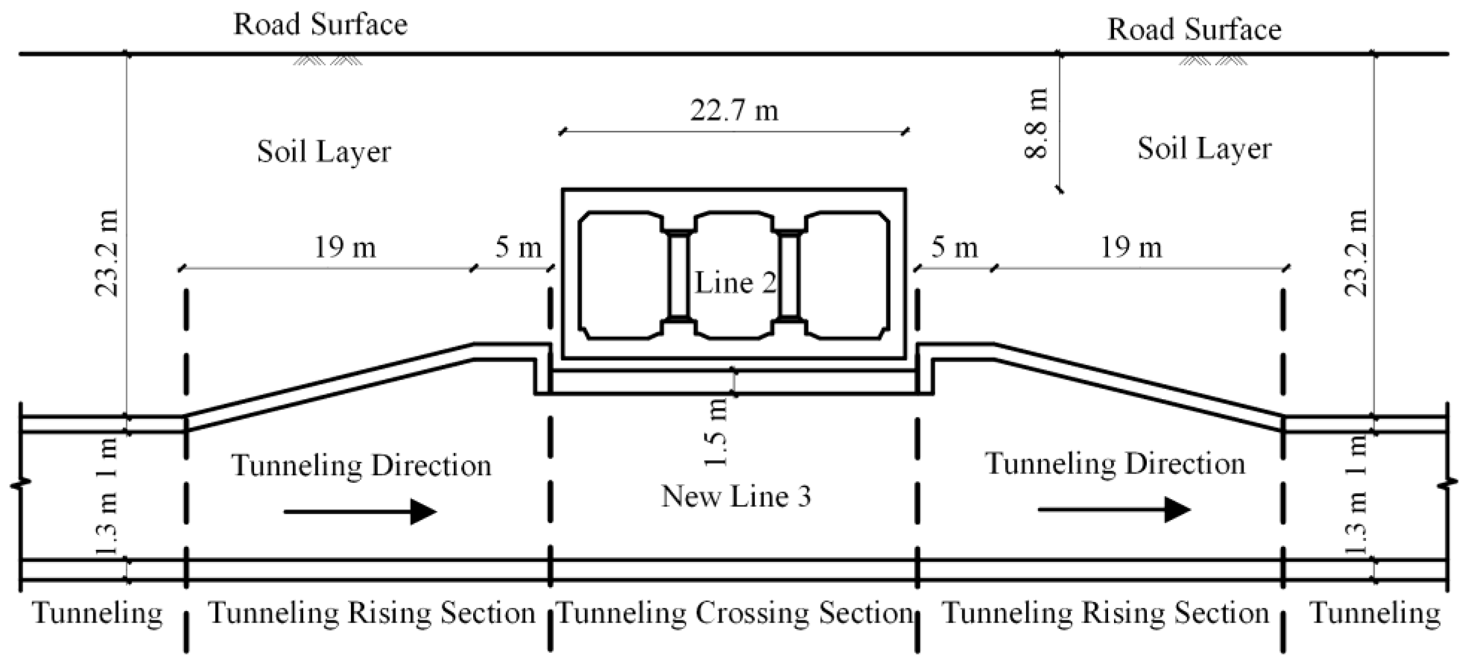
2.1. Prototype Tunnel

As a transfer station between Line 2 and Line 3, Dongsi Shitiao Station was built in 1977 and has been in operation for nearly half a century. Dongshi Sitiao Station of the existing Subway Line 2 is an underground double-deck open-cut station with a north-south direction. The existing subway Line 3 station is arranged in the east-west direction. The main structure is 236 m long and 22.7 m wide. The existing subway station has the same square section frame structure. The existing subway station structures are supported by reinforced concrete lining and steel pipe columns, which are 236 m long and 22.7 m wide. The thickness of the roof, floor, and side wall of each tunnel is 1.2 m, 1.3 m, and 1.3 m, respectively. There are deformation joints at the junction of the existing Subway Line 2 and Line 3. The structure of the new Subway Line 3 and the existing Subway Line 2 is crossed, and the length of the station section under the existing Subway Line 2 is 22.3 m. The new section is constructed in the form of a straight wall structure. The plane diagram of the position of the new structure and the existing subway structure is shown in Figure 2, and the cross section and longitudinal section are shown in Figure 3 and Figure 4.

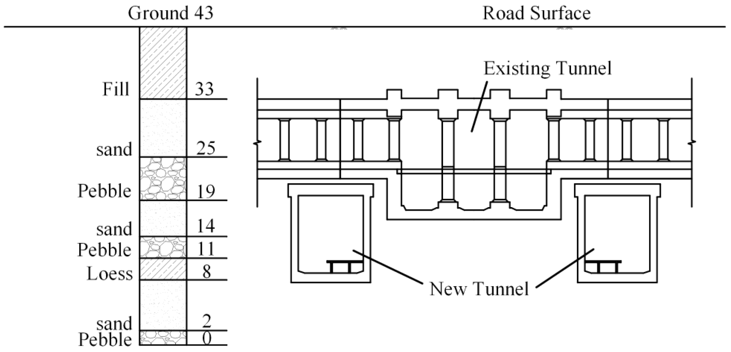
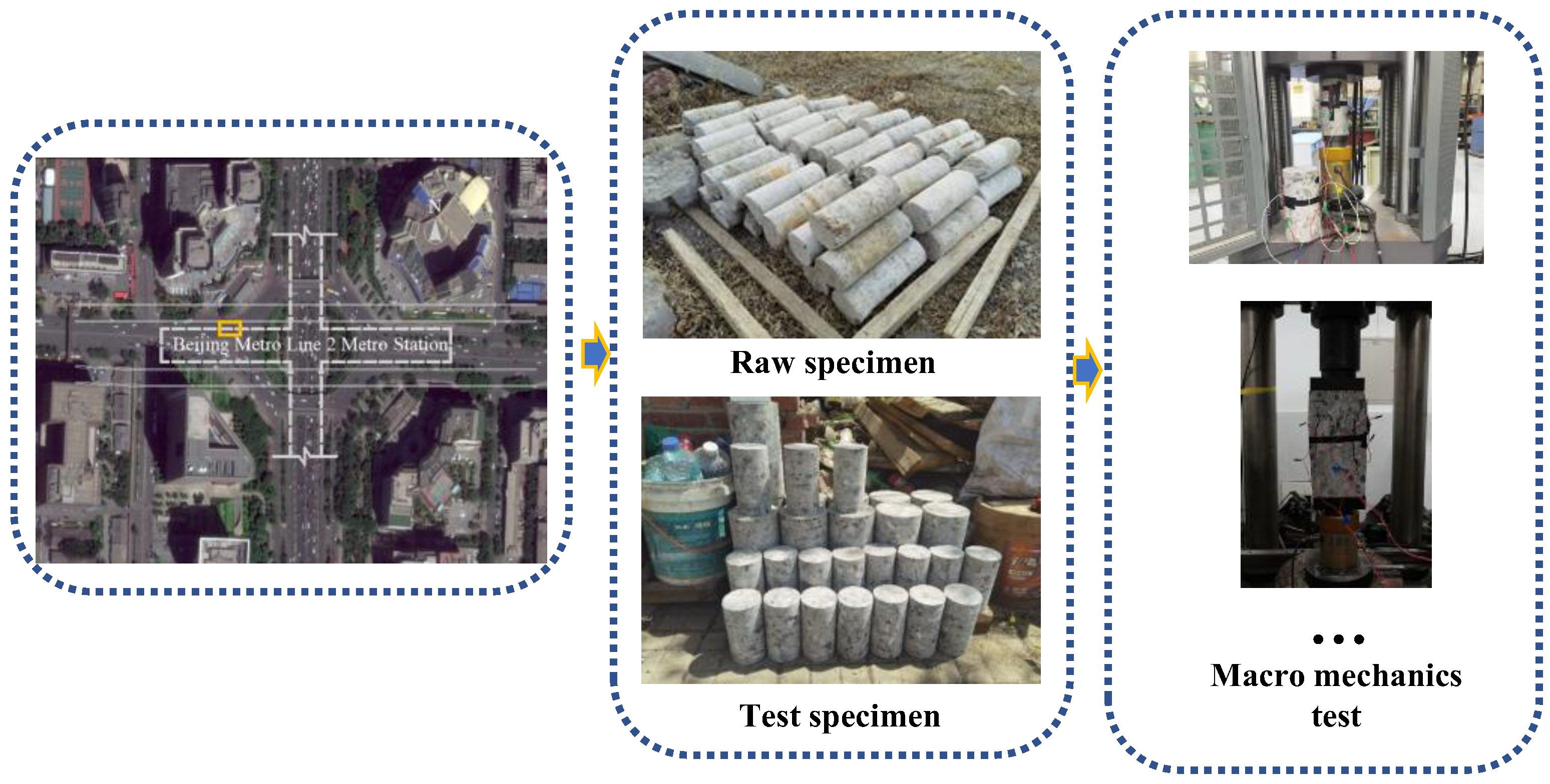
2.2. Geological Conditions

Dongsi Shitiao Station of Beijing Subway Line 2 is located in the central part of Beijing, in the plain landform area [10]. The soil layer of the subway station is divided into two layers: the artificial filling soil layer and the general quaternary alluvial and diluvial layer, which are mainly artificial filling soil, silt, clay soil, sand soil, round gravel, and pebbles [55,56] (Figure 5).
According to the geological survey data, the composition of groundwater detection and groundwater pressure is small, and the chemical composition of groundwater on the reinforced concrete structure shows almost no corrosion. The site opening and the early station structure state inspection showed that the asphalt waterproof layer was completely protected, and there was no water leakage in the main structure. Therefore, the influence of groundwater on the structure was not considered in this study.

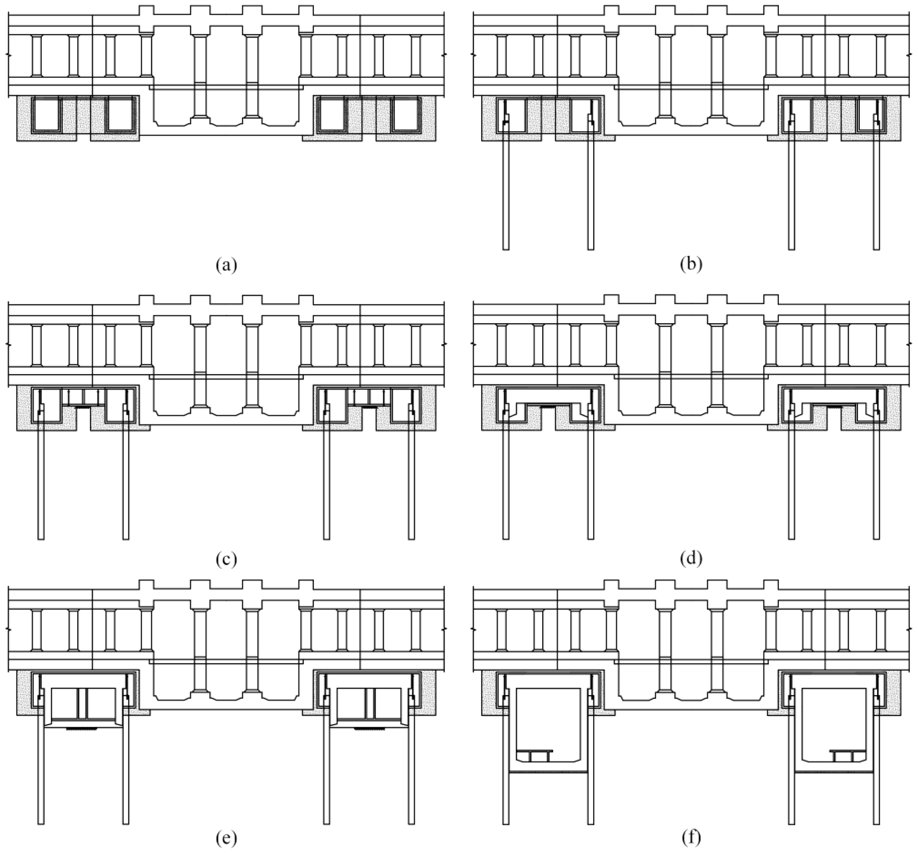
2.3. Construction Process

The construction process of the pre-support technology based on the PBA method under the existing Line 2 is more complicated, including 6 steps (Figure 6).
(a)
The excavation face is reinforced by grouting in this method, and the symmetrical pilot tunnel is constructed by the bench method. After the construction of the pilot tunnel is completed, the back of the pilot tunnel should be grouted to ensure that the roof of the pilot tunnel is closely attached to the floor of the existing Line 2.
(b)
Bored piles are constructed in the pilot tunnel, and jacks are set on the top of the pile to support the top of the pilot tunnel. Concrete support is applied to grout the back and top of the support to increase the connection (Figure 7).
(c)
Excavate the middle guide hole and use the step method to excavate. After the initial support of the construction is completed, the jack is applied.
(d)
The roof and waterproof layer of the new tunnel are constructed.
(e)
The side wall and waterproof layer of the new tunnel are constructed.
(f)
The floor and waterproof layer of the new tunnel are constructed, and the construction of the main structure of the station is completed.

3. Field Test

In order to study the influence of the underpass construction process on the existing Line 2, the structural deformation of the Dongsi Shitiao station and the adjacent section mileage K3 + 290~K3 + 560 was detected.

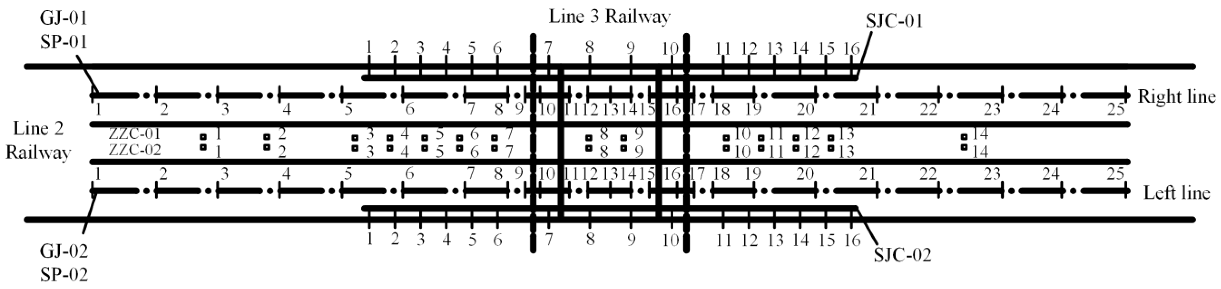
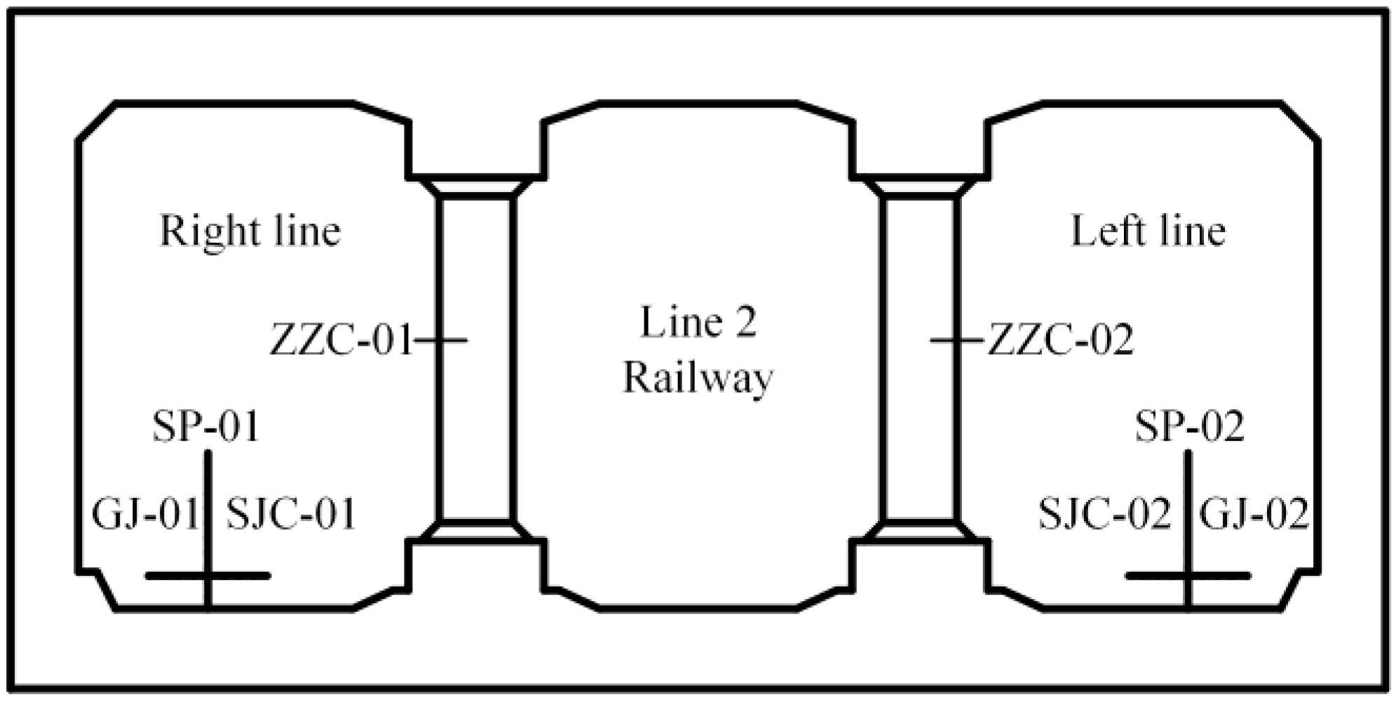
3.1. Monitoring Scheme

The monitoring method adopts two methods: manual monitoring and automatic monitoring. The manual monitoring approach primarily employs a gauge ruler and spirit level for periodic inspection of track gauge and crosslevel, with measurements conducted through manual operation. Manual monitoring includes track level monitoring and track spacing monitoring, and 25 measuring points are set for each track (Figure 8 and Figure 9). The displacement variations of track gauge and crosslevel are used to understand the impact of construction processes on metro operation [57,58,59,60].
The automated monitoring method involves real-time collection and processing of displacement data of existing structures through a monitoring system. When the early-warning threshold is exceeded, the system will automatically trigger an alarm. The real-time monitoring system consists of sensors, data acquisition equipment, a computer, and a software system. The automatic monitoring is the real-time monitoring of the structural deformation of the existing Line 2. The monitoring content is the deformation of the bearing column and the floor of the existing Line 2, and 14 and 16 measuring points are set, respectively (Figure 8 and Figure 9). The monitoring of load-bearing columns and floor slabs of the existing Line 2 is implemented to understand the displacement impact of construction processes on the load-bearing structures of existing structures.

3.2. Monitoring Results and Analysis

To analyze the influence of the construction method on the existing subway structure, the monitoring data are divided into four stages according to the key steps in the construction method: stage 1, stage 2, stage 3, and stage 4. The monitoring standard adopts the ‘Technical Specification for Monitoring and Measurement of Metro Engineering (DB11/490-2007)’ [61].
Stage 1: Construction begins, symmetrically excavates the side pilot tunnel, constructs the bored pile, sets the top of the jack support pilot tunnel, and applies the concrete support.
Stage 2: Excavate the middle pilot tunnel and apply the jack.
Stage 3: The construction of the new tunnel roof is completed.
Stage 4: The main construction of the new tunnel is completed.

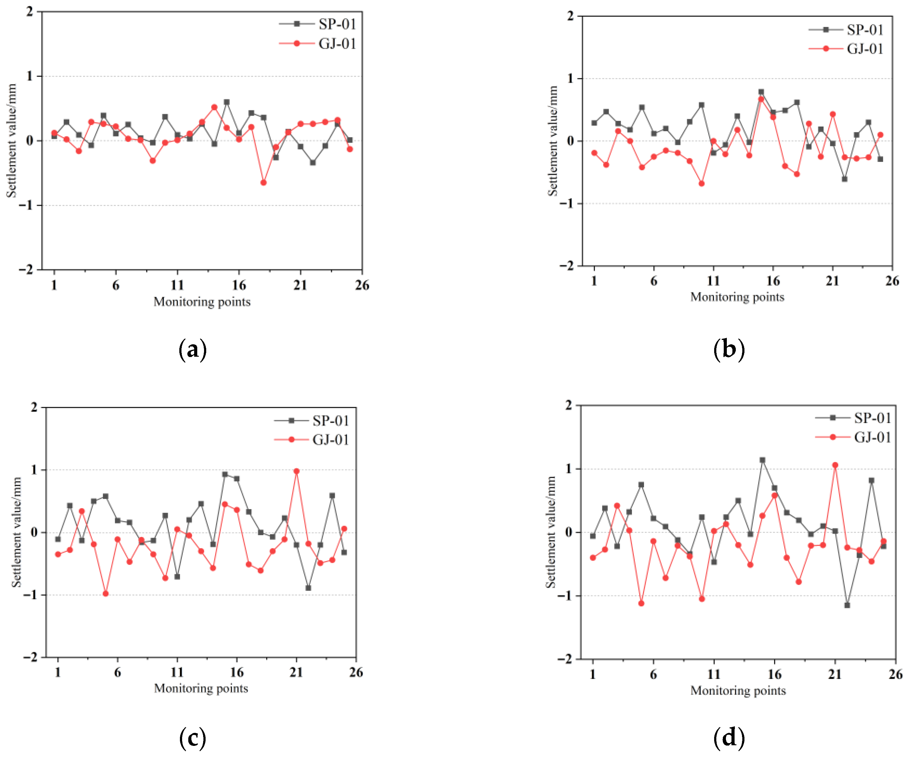
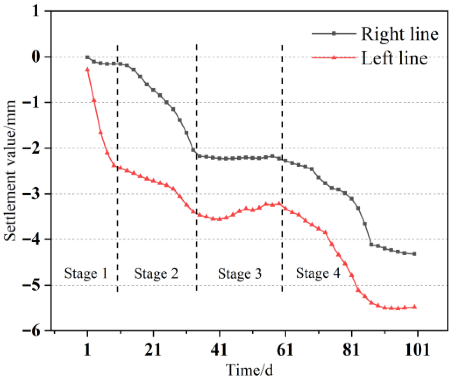
3.2.1. Track Spacing and Track Level

Taking the two-line track as the research object, the changes in track spacing and track level in different stages are shown.
Taking the right line of the existing Line 2 as the monitoring research object, the data of 25 monitoring points of GJ-01 and SP-01 were extracted.
Through the monitoring data (Figure 10), it can be seen that in stages 1, 2, and 3, the change of track spacing and track level is not much different.
The results show that the deformation of the structure in the first three construction stages has not changed greatly, and the deformation is in a small range. In stage 4, the fluctuation range of track spacing and track level obviously increases.
The change in track spacing and track level is mainly caused by the deformation of the track slab, and the change in the track slab is mainly related to the deformation of the tunnel structure floor. The increase in monitoring data fluctuation may be caused by the increase in settlement [52].

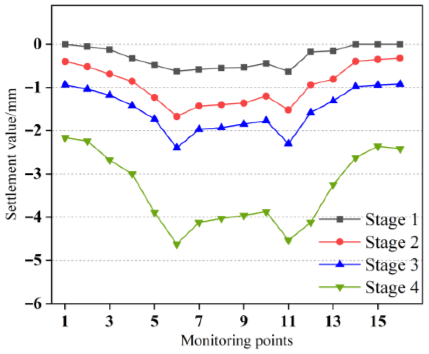
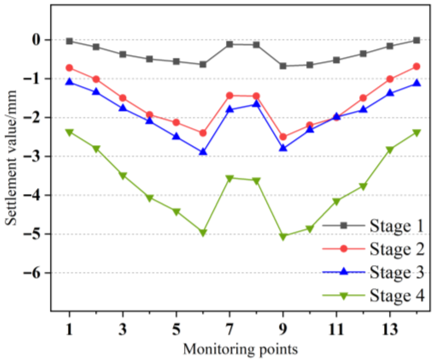
3.2.2. Floor and Load-Bearing Column

The settlement changes of the floor and load-bearing columns at different stages were studied. The right line of the existing Subway Line 2 was taken as the monitoring research object, and the data of SCJ-1 and ZZC-1 monitoring points were extracted.
Figure 11 shows the settlement changes of the floor of the existing Subway Line 2 in different stages with the monitoring point of SCJ-1 as the research object. Figure 12 shows the settlement changes of the load-bearing columns of the existing subway line 2 at different stages with the detection point of ZZC-1 as the research object. Figure 13 shows the settlement characteristics of the construction process of the floor of the existing subway line 2 of the two lines.
It can be seen from the monitoring data that in stages 1, 2, and 3, the deformation of the floor and load-bearing columns of the existing Subway Line 2 is in a small range, and the difference in the change of monitoring points is not large. The deformation of each monitoring point accounts for about 15% to 40% of the total deformation.
The 60% to 85% deformation of the station floor and load-bearing column mainly occurs in stage 4. The main reason for this discovery is that the soil disturbance in the first three construction stages is small, and the disturbance caused by soil excavation in the fourth stage is the largest, which leads to a change in the bearing capacity of the structure and an increase in settlement.
In the process of the new tunnel closely passing through the existing subway line 2, the construction provides displacement support for the jack by applying the cast-in-place pile and reduces the settlement caused by soil disturbance through the rigid contact between the jack and the bottom plate of the existing subway line 2.
In the early stage of construction, there is no large fluctuation in track spacing and track level. In the later stage of construction, the deformation of track spacing and track level is caused by the increase of soil disturbance, and the change range is still within the range of 1~3 cm of the adjustable height of the track gasket. It shows that the construction method of controlling settlement by pre-support technology effectively controls the construction deformation in the early stage and ensures the rail surface of the existing Subway Line 2 during the operation period. If there is a similar project, it is necessary to pay attention to the increase of construction measures to control soil disturbance in the later stage of construction [62,63].
Because the underpass construction starts from the left line, compared with the right line, it is easy to cause uneven settlement of the soil in the early stage of construction, resulting in weak bearing capacity, and the settlement of the right line is smaller than that of the left line.
It can be seen from the above that the pre-supporting technical method can effectively control the settlement of adjacent structures caused by excavation and reduce the impact of construction on adjacent structures.

4. Simulation Methods and Materials

The study takes the construction of the new main structure of Dongsi Shitiao Station on Metro Line 3 as the background, uses the three-dimensional finite difference program FLAC3D for simulation calculations, provides material parameters for the model through geotechnical investigation data and laboratory tests, and investigates the impact of the proposed construction method on the displacement and stress variations of existing structures.

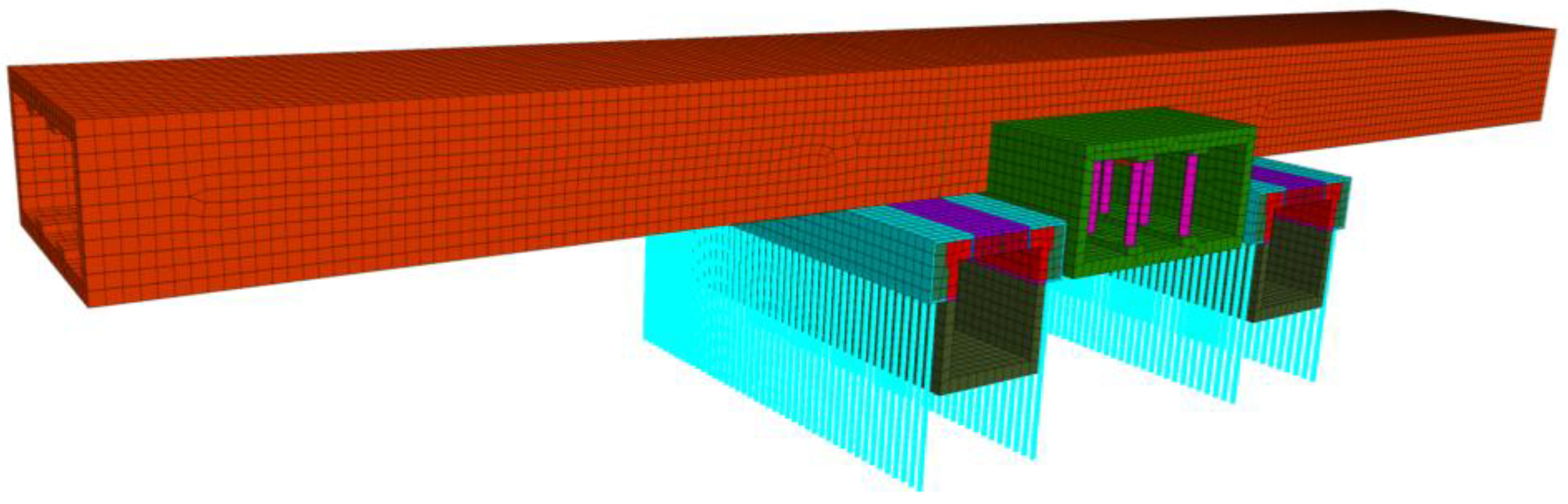
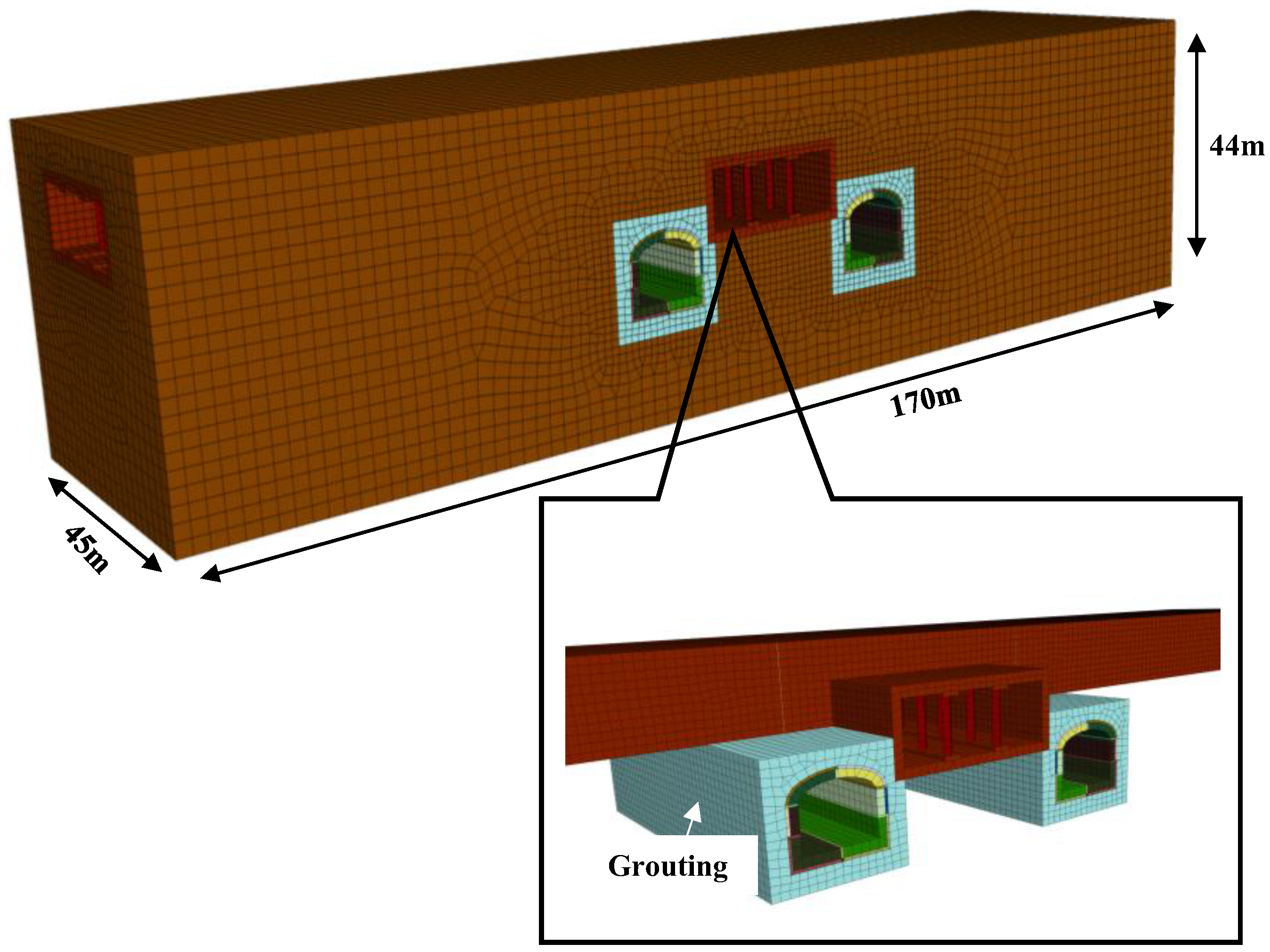
4.1. Finite Difference Model

The model calculation scope is taken as 170 m in length, 45 m in width, and 44 m in height, considering the size effect and stratum characteristics. The bottom of the model is applied with fixed constraints, the four surrounding boundaries are applied with horizontal constraints, and the top surface is free (Figure 14, Figure 15 and Figure 16).
In the model, the soil, the existing station structure, and the new tunnel are simulated by solid elements, and the Mohr–Coulomb criterion is adopted. Each soil layer is assumed to be homogeneous, isotropic, and elastic. Piles and jacks are simulated by the beam element in the software.
In the process of underpass construction, the pilot tunnel will be constructed after the tunnel excavation is completed, and then the cast-in-place pile, jack, and concrete support will be installed. In this numerical simulation, the cast-in-place pile and the jack are applied simultaneously.
Unlike the numerical models in other studies, the model in this paper simulates bored piles and jacks using beam elements, achieving the provision of support forces in different construction stages. Meanwhile, it reduces the additional computational time caused by modeling bored piles as solid elements [64,65,66,67].

4.2. Material and Parameters

The material parameters in the model are divided into the material parameters of the stratum, the existing structure, and the new structure. The parameters of the stratum materials are set according to the actual parameters in the geological survey report. The parameters of each stratum are shown in Table 1.
The sampling of existing structural materials selects the concrete of the side wall of the existing subway station of Line 3. By using the method of combining a water drill and wire saw, the large volume of concrete block is processed into a cylinder, and the sample is processed in the processing plant according to the test requirements. The existing structural parameters are mainly the material parameters of the existing structural concrete. A series of tests were carried out on the concrete of the existing structure, including a uniaxial compression test, elastic modulus, and Poisson’s ratio test (Figure 17). According to the test data, the strength grade of the existing line structure concrete is about C40, the elastic modulus of the model material is 32 GPa, and the Poisson’s ratio is 0.2.
The material parameters of the supporting structure are shown in Table 2.

4.3. Construction Schemes

To study the influence of different construction methods on the settlement deformation of existing subway structures, this paper also simulates the construction of the cross diaphragm method (CRD) to compare the construction methods of this paper (Figure 18). The CRD method is a cross-middle partition wall method. The disturbance of excavation to the soil is controlled by the pre-grouting method and small chamber construction to reduce the settlement. This method is usually used for tunnel construction in weak strata.
The material parameters of the existing subway structure, stratum, and new tunnel in the model are consistent with the previous model. The simulation of the grouting layer is realized by changing the mechanical parameters of the soil in the grouting area.
Table 3 shows that the construction characteristics of the CRD method and the pre-support technology method are compared.
To study the influence of different construction methods on the operation of the existing subway structure, the floor deformation of the subway is studied, and the position of the measurement point is the same as that of the monitoring point.

5. Simulation Results and Analysis

Through numerical simulation and construction monitoring, this study investigates the displacement and stress variations of the existing Line 2 station structure during the construction of the method proposed in this paper. By comparing with the CRD method, it examines the deformation control effect of the proposed method on existing structures during the construction process.

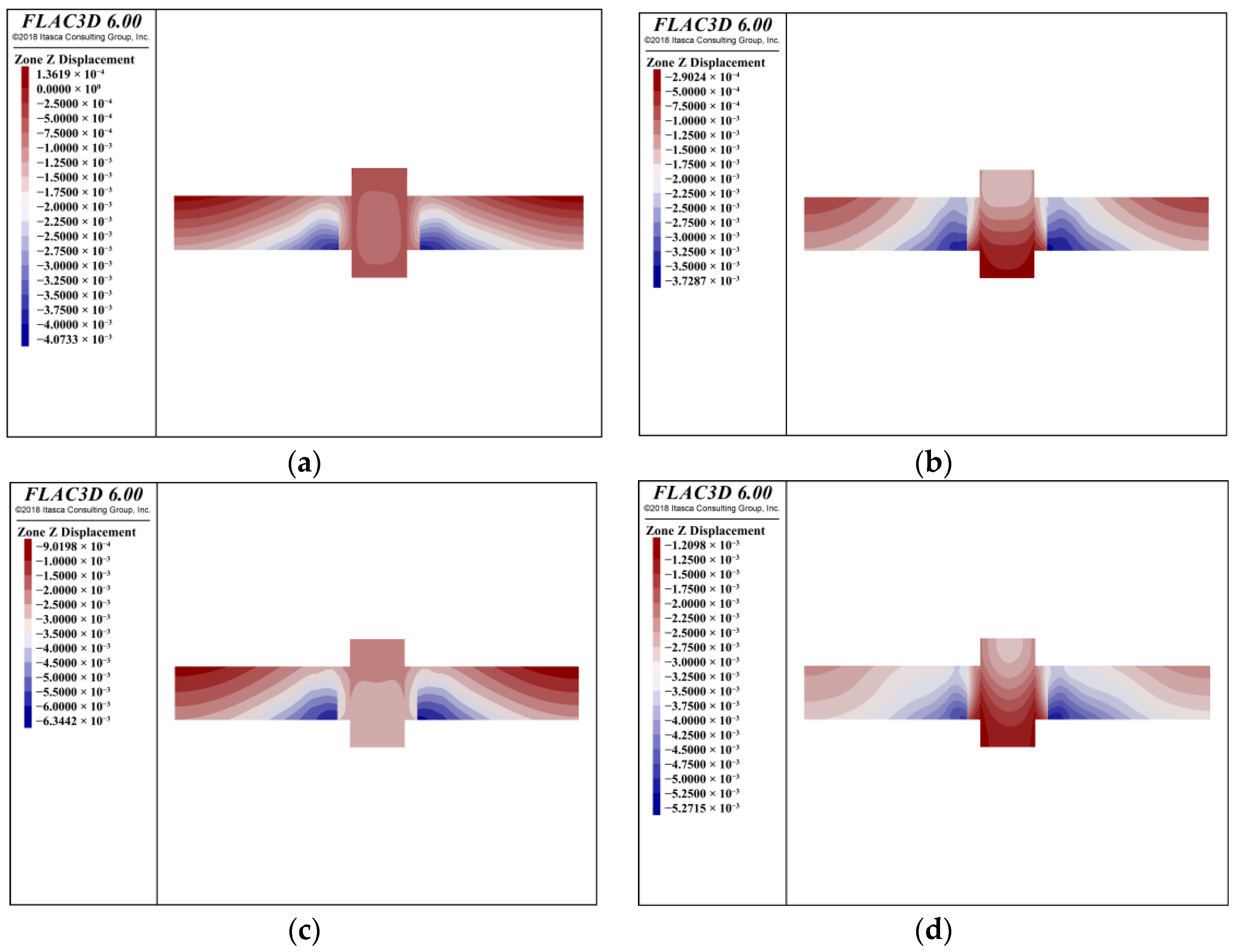
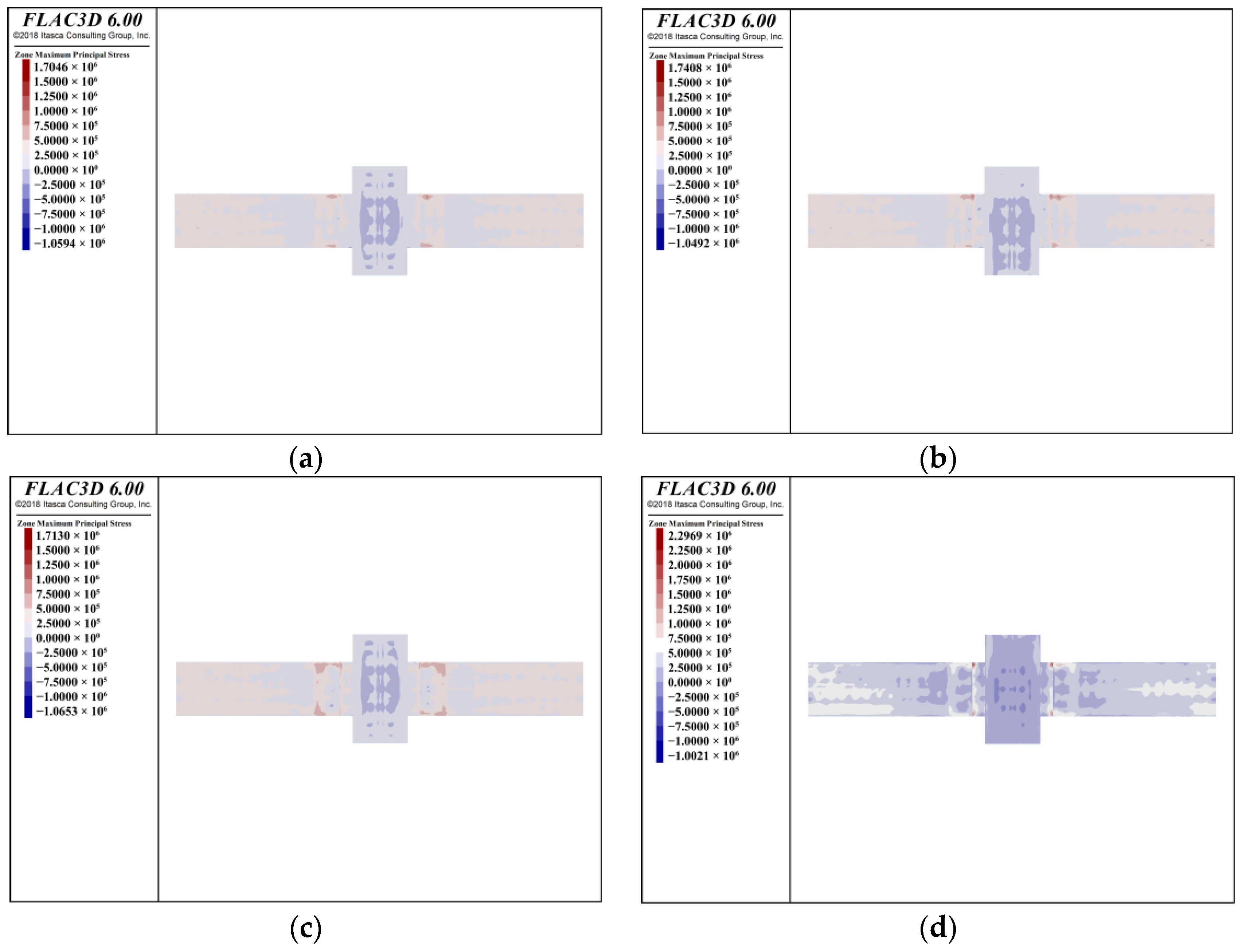
5.1. Settlement and Stress Analysis of the Existing Subway Line 2 Structure

This simulation studies the influence of the construction process on the deformation and stress changes of the floor of the existing subway structure.
Figure 19 shows the displacement of the existing Subway Line 2 structure floor in the z direction during the construction process. It can be seen that after the excavation of the side guide hole and the construction of the jack support in Stage 1, the maximum displacement of the existing structure is 4 mm, which is located at the joint of the deformation joint. The area with large deformation is more concentrated at the deformation joint; the main reason is that the connection strength at the deformation joint is weak and it is easy to form the deformation. After the excavation of the pilot tunnel and the construction of the jack support in Stage 2, the maximum displacement of the existing structure is 3.7 mm, which is located at the deformation joint, and the large deformation area is more uniform than that in Stage 1. After the construction of the new tunnel close to the roof in Stage 3, the maximum displacement of the existing structure is 6 mm, which is also located in the deformation joint, and the larger deformation area is concentrated in the deformation joint. After the completion of the soil structure of the new tunnel in Stage 4, the maximum displacement of the existing structure is 5.2 mm, which is located in the deformation joint, and the deformation area is more uniform than that in Stage 3.
The results show that during the construction process, the maximum displacement position after each stage of construction is the deformation joint. The deformation joint is located in the area under the construction of the new tunnel, which leads to an increase in settlement on both sides of the deformation joint in the early stage of construction. This construction method can effectively control the long-term deformation of the deformation joint and reduce the settlement of the deformation joint caused by later construction. Therefore, attention should be paid to monitoring the displacement near the deformation joint during the construction process.
Figure 20 shows the maximum principal stress of the floor of the existing Subway Line 2 during the construction process. It can be seen that in Stage 1, the maximum stress of the floor of the existing Subway Line 2 is about −0.25 MPa, which is located near the construction area. In Stage 2, the maximum stress of the floor of the existing Subway Line 2 is about −0.25 MPa, which is located near the construction area, and the maximum stress range is larger than that of Stage 1. In Stage 3, the maximum stress of the existing Subway Line 2 floor is about −0.25 MPa, and the maximum stress range is larger than that of Stage 2. The maximum tension range is larger than that of stage 2. In Stage 4, the maximum stress of the existing Subway Line 2 floor is about −0.5 MPa.
The results show that the pre-support technology construction method can effectively control the settlement deformation of the existing Line 2 and reduce the stress damage of the floor due to excessive settlement.
In the later stage of construction, due to the large excavation area, the vertical soil stress changes, which change the bearing capacity of the existing Subway Line 2, causing the deformation of the floor and leading to an increase in the stress change of the floor.
Therefore, in the later stage of construction, the construction speed should not be too fast, and attention should be paid to monitoring the displacement of the floor to prevent the occurrence of accidents.

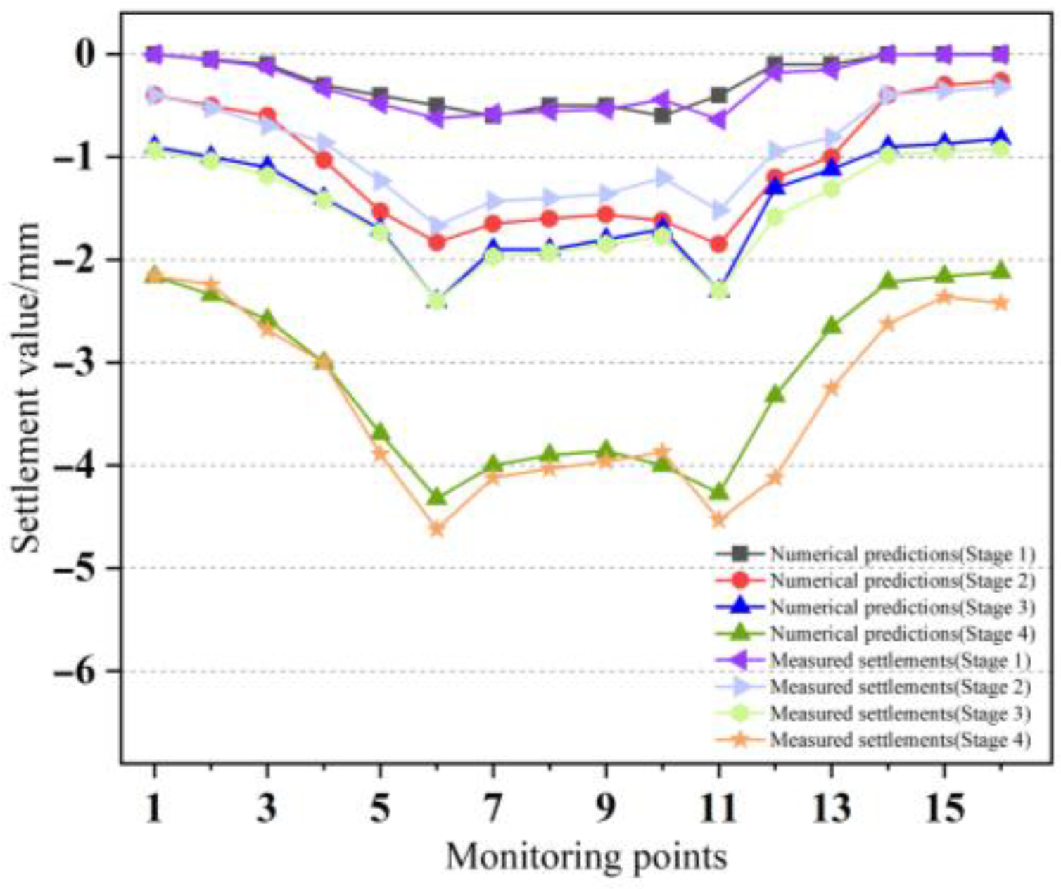
5.2. Comparison Between Field Tests and Simulation

Figure 21 shows the simulation results and field monitoring results of the settlement of the existing Subway Line 2 floor in four stages. The settlement curves of the floor show a single convex groove shape. The location of the maximum settlement deformation is near the deformation joint of the subway station. The settlement of the floor decreases gradually from the middle to both sides. The field monitoring results show that the maximum settlement value of the surface is −4.7 mm. The value of the simulation result is −4.2 mm. The numerical simulation results are close to the field monitoring data. Therefore, the numerical simulation of the subway station construction process is reasonable.
Through the comparative analysis of field monitoring results and numerical simulation results, the feasibility of model parameter selection is confirmed, which indicates that the selection of model parameters is feasible. The parameters selected by the model can be used to simulate the subsequent construction process.

5.3. Comparison of Settlement and Stress of the Existing Line 2 by Different Construction Methods

Figure 22 and Figure 23 show the comparison of the settlement of the existing Subway Line 2 floor under the PBA and CRD construction methods. It can be seen from this that the maximum settlement of the floor of the existing Line 2 under the PBA construction method is −5.27 mm, and the position with the maximum settlement is near the deformation joint. The maximum settlement of the floor of the existing Line 2 under the CRD construction method is −61.28 mm, and the position with the maximum settlement is near the existing Line 3 and the deformation joint. By comparing the results of numerical analysis, it can be known that the PBA closely attached under-passing construction method can effectively control the structural settlement, reducing the structural settlement and deformation compared with the CRD construction method. The CRD construction method disturbs the soil mass too much, affecting the bearing capacity of the soil mass. In the actual operation process, problems such as insufficient grouting are likely to occur, affecting the effectiveness of settlement control.
Figure 22 and Figure 23 show the comparison of the floor settlement deformation of existing Line 2 under the pre-supporting technical method and the CRD method. It can be seen that the maximum settlement of the floor of the existing Subway Line 2 under the pre-supporting technical method is −5.27 mm, and the maximum settlement is near the deformation joint. The maximum settlement of the existing Subway Line 2 floor under the CRD method is −61.28 mm, and the maximum settlement is near the existing Line 3 and the deformation joint.
By comparing the numerical analysis results, it can be seen that the pre-supporting technical method can effectively control the structural settlement and reduce the structural deformation compared with the CRD method. The CRD method cannot directly control the settlement deformation of the existing Subway Line 2, and the actual operation process is easy to cause problems such as insufficient grouting, which affects the settlement control effect.
Figure 24 shows the comparison of the stress influence of the existing Line 2 floor with different construction methods.
It can be seen that the maximum compressive stress of the floor under the pre-support technical method is 1 MPa, the maximum tensile stress is 2.29 MPa, and the maximum compressive stress of the floor under the CRD method is 1.07 MPa, and the maximum tensile stress is 2.47 MPa.
According to the comparison of numerical analysis results, the pre-supporting technical method can better control the stress change, and the stress change is smaller than that of the CRD method, which reduces the damage risk of the structure caused by construction.

6. Discussion

According to the field monitoring data and numerical simulation, the following discussion is put forward for the construction method in this paper.
(1)
The on-site monitoring of tracks and the existing Line 2 station structure during construction demonstrates that the pre-support technology effectively controls the disturbance to the structure caused by under-passing excavation, without inducing significant deformation. The numerical simulation of the construction process shows that the pre-support technology can effectively control the stress variation of structures without generating significant tensile and compressive stresses, thus keeping the structures within the elastic deformation range.
(2)
The differences in construction techniques and conditions lead to the fact that existing studies fail to achieve direct contact control over existing structures, thus causing significant soil disturbance during excavation and resulting in substantial deformation of existing structures. The pre-support technology, through the supporting action of bored piles and jacks, provides direct contact support to existing structures, offering more stable support than other construction methods and better controlling the displacement and stress variations of existing structures. The monitoring data of on-site displacement are affected by underground construction, while the numerical model only discusses the influence of the underpass construction process on the existing subway structure and does not consider the influence of other underground construction on the existing subway structure, which needs further study.
(3)
The comparative study on the impact of different construction methods on the existing Line 2 structure shows that the pre-support technology has obvious advantages over the commonly used CRD method, resulting in less displacement deformation and smaller stress variations in the existing Line 2. During the construction process, in the process of pilot tunnel excavation, pile foundation construction, and jack placement, the interval time between the processes should be minimized to ensure that the pile foundation and the jack are closely connected with the existing subway structure floor and ensure that the pile foundation is used as the support point to control the deformation of the subway structure.

7. Conclusions

This paper introduces the pre-supporting technical method based on the pile–beam–arch (PBA) method for existing subway stations, taking the new Line 3 of the Beijing Subway undercrossing the existing Subway Line 2 as an example. The applicable geological condition of this method is a sandy cobble stratum. This method utilizes the characteristics of the PBA method, reduces the deformation of the existing structure, shortens the construction period, and better controls the settlement of the existing structure.
In this paper, the control effect of this method on the settlement of existing structures is analyzed by field monitoring and numerical analysis. From the research results, we can draw the following conclusions:
(1)
The construction method in this paper controls the settlement of existing tunnels through cast-in-place piles, jacks, and crown beams, which is an effective measure to reduce stratum loss and stabilize the settlement of existing tunnels. The settlement deformation of the existing subway station is controlled within 1~3 cm, and the deformation stress is within the concrete strength range of existing structures, with the maximum tensile stress less than 3 MPa.
(2)
The settlement curve of the existing Line 2 floor jumps at the deformation joint. In addition, the section of the existing Line 2 affected by the new tunnel is mainly tilted as a rigid body because its stiffness is higher than that of the surrounding soil. The construction method proposed in this paper causes minimal impact on the deformation displacement of operational stations and slight changes in the smoothness of the subway rail surface. The fluctuation range basically remains within −1 to 1 mm, ensuring the safety of existing subway operations.
(3)
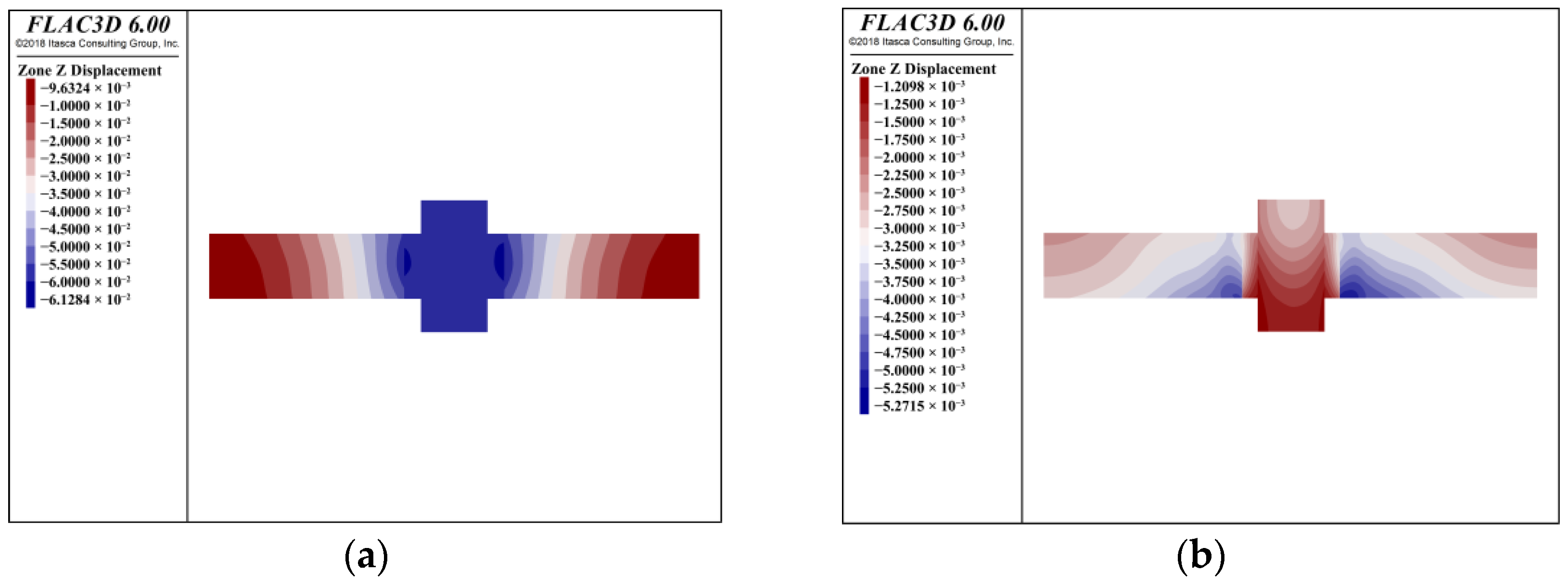
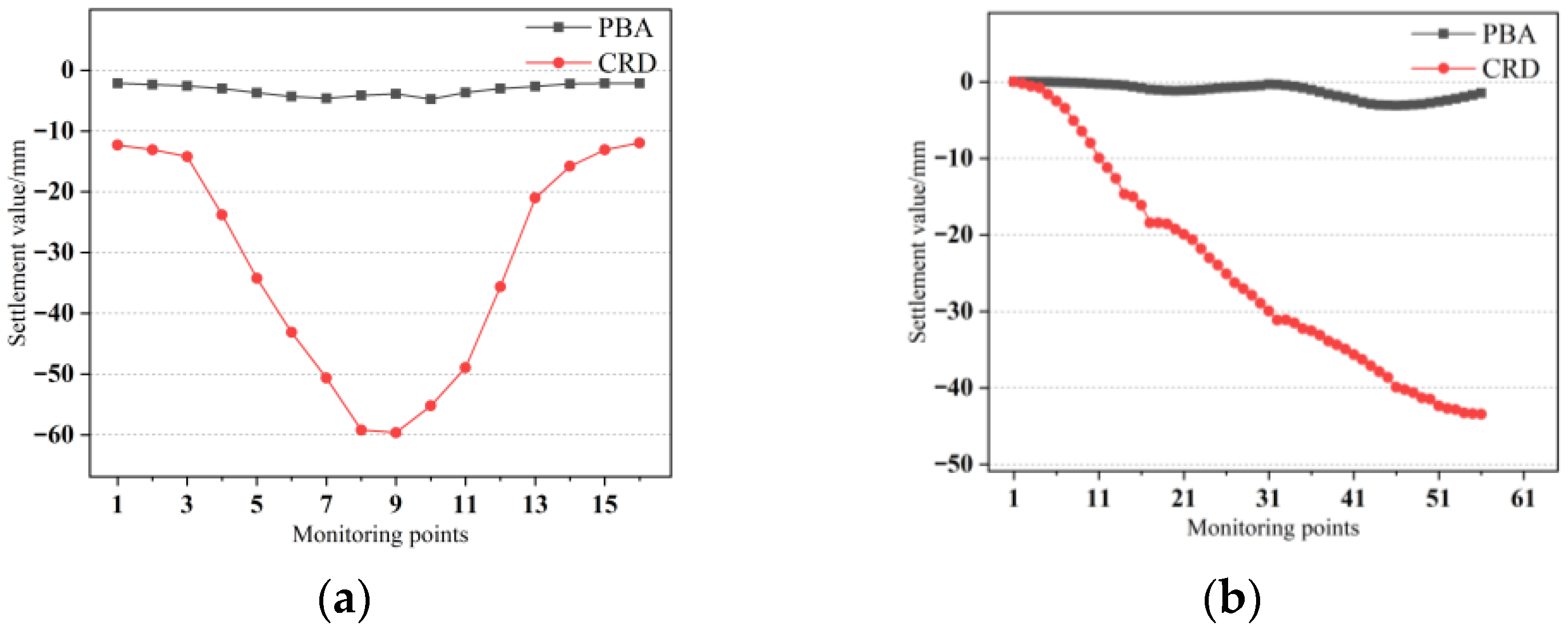
In terms of the deformation control of the existing station structure, the settlement and stress changes of the existing Subway Line 2 under the dross diaphragm (CRD) method are greater than those of the pre-supporting technical method, which has a greater impact on the existing structure during the construction stage. The maximum settlement and maximum tensile stress of the station in the cross diaphragm (CRD) method scheme are −61.28 mm and 2.47 MPa, respectively. The maximum settlement and maximum tensile stress of the station in the pre-support jacking scheme are −5.27 mm and 2.29 MPa, respectively. As a construction scheme, the pre-support technology has less influence on the structural deformation.
(4)
In this paper, by improving the PBA method, the settlement of the existing subway structure is reduced by increasing the support of the existing subway structure during the construction process. The application of this reinforcement measure in tunnel engineering in Beijing is the first time.

Author Contributions

Conceptualization, S.H. and B.Z.; software, B.Z.; validation, S.H., B.Z. and J.Z.; formal analysis, B.Z.; investigation, B.Z., Y.L. and J.M.; resources, J.H. and J.Z.; data curation, B.Z.; writing—original draft preparation, B.Z. All authors have read and agreed to the published version of the manuscript.

Funding

This research received no external funding.

Data Availability Statement

Data is contained within the article.

Acknowledgments

During the preparation of this manuscript, the author used DeepSeek R1 to translate the part of the paper. The authors have reviewed and edited the output and take full responsibility for the content of this publication.

Conflicts of Interest

The authors declare no conflicts of interest.

References

  1. Gao, G.; Zhuang, Y.; Wang, K.; Chen, L. Influence of Benoto Bored Pile Construction on Nearby Existing Tunnel: A Case Study. Soils Found. 2019, 59, 544–555. [Google Scholar] [CrossRef]
  2. Meng, F.; Chen, R.; Xu, Y.; Wu, K.; Wu, H.; Liu, Y. Contributions to Responses of Existing Tunnel Subjected to Nearby Excavation: A Review. Tunn. Undergr. Space Technol. 2022, 119, 104195. [Google Scholar] [CrossRef]
  3. Zhou, F.; Zhou, P.; Li, J.; Lin, J.; Ge, T.; Deng, S.; Ren, R.; Wang, Z. Deformation Characteristics and Failure Evolution Process of the Existing Metro Station under Unilateral Deep Excavation. Eng. Fail. Anal. 2022, 131, 105870. [Google Scholar] [CrossRef]
  4. Zhang, L.; Liu, P.; Yan, X.; Zhao, X. Middle Displacement Monitoring of Medium–Small Span Bridges Based on Laser Technology. Struct. Control Health Monit. 2020, 27, e2509. [Google Scholar] [CrossRef]
  5. Nematollahi, M.; Molladavoodi, H.; Dias, D. Three-Dimensional Numerical Simulation of the Shiraz Subway Second Line—Influence of the Segmental Joints Geometry and of the Lagging Distance between Twin Tunnels’ Faces. Eur. J. Environ. Civ. Eng. 2020, 24, 1606–1622. [Google Scholar] [CrossRef]
  6. Cai, Q.; Hu, Q.; Ma, G. Improved Hybrid Reasoning Approach to Safety Risk Perception under Uncertainty for Mountain Tunnel Construction. J. Constr. Eng. Manag. 2021, 147, 04021105. [Google Scholar] [CrossRef]
  7. Yin, Y.; Wang, J.; Zou, B.; Zhang, J.; Su, Y.; Sun, Q. Evaluation of Controlled Blasting Quality for Rock-Mass Tunneling Based on Multiple Indices. J. Constr. Eng. Manag. 2023, 149, 04022155. [Google Scholar] [CrossRef]
  8. Ding, Z.; Zhang, M.-B.; Zhang, X.; Wei, X.-J. Theoretical Analysis on the Deformation of Existing Tunnel Caused by Under-Crossing of Large-Diameter Slurry Shield Considering Construction Factors. Tunn. Undergr. Space Technol. 2023, 133, 104913. [Google Scholar] [CrossRef]
  9. Guo, X.; Jiang, A. Study on the Stability of a Large-Span Subway Station Constructed by Combining with the Shaft and Arch Cover Method. Tunn. Undergr. Space Technol. 2022, 127, 104582. [Google Scholar] [CrossRef]
  10. Xu, X.; Li, Z.; Fang, Q.; Zheng, H. Challenges and Countermeasures for Using Pile-Beam-Arch Approach to Enlarge Large-Diameter Shield Tunnel to Subway Station. Tunn. Undergr. Space Technol. 2020, 98, 103326. [Google Scholar] [CrossRef]
  11. Fang, Q.; Liu, X.; Zeng, K.; Zhang, X.; Zhou, M.; Du, J. Centrifuge Modelling of Tunnelling below Existing Twin Tunnels with Different Types of Support. Undergr. Space 2022, 7, 1125–1138. [Google Scholar] [CrossRef]
  12. Chang, J.; Huang, H.; Zhang, D.; Wu, H.; Yan, J. Transverse Deformational Behaviors of Segmental Lining during Shield Tunneling: A Case Study. Struct. Control Health Monit. 2022, 29, e3097. [Google Scholar] [CrossRef]
  13. Zhang, C.; Chen, K.; Yang, J.; Fu, J.; Wang, S.; Xie, Y. Reuse of Discharged Soil from Slurry Shield Tunnel Construction as Synchronous Grouting Material. J. Constr. Eng. Manag. 2022, 148, 04021193. [Google Scholar] [CrossRef]
  14. Zhou, M.; Su, X.; Chen, Y.; An, L. New Technologies and Challenges in the Construction of the Immersed Tube Tunnel of the Hong Kong-Zhuhai-Macao Link. Struct. Eng. Int. 2022, 32, 455–464. [Google Scholar] [CrossRef]
  15. Quan, X.J.; Gao, J.H.; Wang, B.; Xu, J.H.; Zhang, Q.Z. Damage Mechanisms of Soft Rock Tunnels in the Western China: A Case Study on the Dujiashan Tunnel. Struct. Eng. Int. 2022, 32, 369–377. [Google Scholar] [CrossRef]
  16. Wang, F.; Shi, J.; Huang, H.; Zhang, D.; Liu, D. A Horizontal Convergence Monitoring Method Based on Wireless Tilt Sensors for Shield Tunnels with Straight Joints. Struct. Infrastruct. Eng. 2021, 17, 1194–1209. [Google Scholar] [CrossRef]
  17. Jin, D.; Yuan, D.; Ng, Y.C.H.; Pan, Y. Effect of an Undercrossing Tunnel Excavation on an Existing Tunnel Considering Nonlinear Soil-Tunnel Interaction. Tunn. Undergr. Space Technol. 2022, 130, 104571. [Google Scholar] [CrossRef]
  18. Weng, X.; Yu, H.; Niu, H.; Hu, J.; Han, W.; Huang, X. Interactive Effects of Crossing Tunnel Construction on Existing Tunnel: Three-Dimensional Centrifugal Test and Numerical Analyses. Transp. Geotech. 2022, 35, 100789. [Google Scholar] [CrossRef]
  19. Yu, J.; Li, H.; Huang, M.; Li, Y.; Tan, J.Q.W.; Guo, Y. Timoshenko-Beam-Based Response of Existing Tunnel to Single Tunneling underneath and Numerical Verification of Opening and Dislocation. Comput. Geotech. 2022, 147, 104757. [Google Scholar] [CrossRef]
  20. Gan, X.; Yu, J.; Gong, X.; Liu, N.; Zheng, D. Behaviours of Existing Shield Tunnels Due to Tunnelling underneath Considering Asymmetric Ground Settlements. Undergr. Space 2022, 7, 882–897. [Google Scholar] [CrossRef]
  21. Chen, J.; Zhang, J.; Chen, B.; Lu, G. The Influence of the Underpassing Frozen Connecting Passage on the Deformation of the Existing Tunnel. Res. Cold Arid Reg. 2022, 14, 258–266. [Google Scholar] [CrossRef]
  22. Fu, C.; Gao, Y. Numerical Analysis on the Behavior of Existing Tunnels Subjected to the Undercrossed Shield Tunneling at a Small Proximity. Adv. Civ. Eng. 2020, 2020, 8823331. [Google Scholar] [CrossRef]
  23. Zhou, Z.; Chen, Y.; Liu, Z.; Miao, L. Theoretical Prediction Model for Deformations Caused by Construction of New Tunnels Undercrossing Existing Tunnels Based on the Equivalent Layered Method. Comput. Geotech. 2020, 123, 103565. [Google Scholar] [CrossRef]
  24. Li, Y.; Zhou, G.; Tang, C.; Wang, S.; Wang, K.; Wang, T. Influence of Undercrossing Tunnel Excavation on the Settlement of a Metro Station in Dalian. Bull. Eng. Geol. Environ. 2021, 80, 4673–4687. [Google Scholar] [CrossRef]
  25. Li, J.; Fang, Q.; Liu, X.; Du, J.; Wang, G.; Wang, J. Mechanical Behaviors of Existing Large-Diameter Tunnel Induced by Horseshoe-Shaped Undercrossing Twin Tunnels in Gravel. Appl. Sci. 2022, 12, 7344. [Google Scholar] [CrossRef]
  26. Wei, X.; Zhang, M.; Ma, S.; Xia, C.; Liu, X.; Ding, Z. Deformation Characteristics of Existing Twin Tunnels Induced by Double Shield Undercrossing with Prereinforcement: A Case Study in Hangzhou. Adv. Civ. Eng. 2021, 2021, 7869899. [Google Scholar] [CrossRef]
  27. Lin, X.-T.; Chen, R.-P.; Wu, H.-N.; Cheng, H.-Z. Deformation Behaviors of Existing Tunnels Caused by Shield Tunneling Undercrossing with Oblique Angle. Tunn. Undergr. Space Technol. 2019, 89, 78–90. [Google Scholar] [CrossRef]
  28. Liu, X.; Fang, Q.; Zhang, D. Mechanical Responses of Existing Tunnel Due to New Tunnelling below without Clearance. Tunn. Undergr. Space Technol. 2018, 80, 44–52. [Google Scholar] [CrossRef]
  29. Guan, L.; Wang, P.; Ding, H.; Qin, J.; Xu, C.; Feng, G. Analysis of Settlement of an Existing Tunnel Subjected to Undercrossing Tunneling Based on the Modified Vlasov Model. Int. J. Geomech. 2024, 24, 04023300. [Google Scholar] [CrossRef]
  30. Zhou, Z.; Zhou, X.; Li, L.; Liu, X.; Wang, L.; Wang, Z. The Construction Methods and Control Mechanisms for Subway Station Undercrossing an Existing Tunnel at Zero Distance. Appl. Sci. 2023, 13, 8826. [Google Scholar] [CrossRef]
  31. Liang, J.; Tang, X.; Wang, T.; Lin, W.; Yan, J.; Fu, C. Analysis for Ground Deformation Induced by Undercrossed Shield Tunnels at a Small Proximity Based on Equivalent Layer Method. Sustainability 2022, 14, 9972. [Google Scholar] [CrossRef]
  32. Zhu, Q.; Ding, Y. Impact of New Undercrossing Tunnel Excavation on the Stability of the Existing Tunnel. Front. Earth Sci. 2022, 10, 915882. [Google Scholar] [CrossRef]
  33. Lai, H.; Zheng, H.; Chen, R.; Kang, Z.; Liu, Y. Settlement Behaviors of Existing Tunnel Caused by Obliquely Under-Crossing Shield Tunneling in Close Proximity with Small Intersection Angle. Tunn. Undergr. Space Technol. 2020, 97, 103258. [Google Scholar] [CrossRef]
  34. Chen, R.-P.; Lin, X.-T.; Kang, X.; Zhong, Z.-Q.; Liu, Y.; Zhang, P.; Wu, H.-N. Deformation and Stress Characteristics of Existing Twin Tunnels Induced by Close-Distance EPBS under-Crossing. Tunn. Undergr. Space Technol. 2018, 82, 468–481. [Google Scholar] [CrossRef]
  35. Jin, D.; Yuan, D.; Li, X.; Zheng, H. Analysis of the Settlement of an Existing Tunnel Induced by Shield Tunneling Underneath. Tunn. Undergr. Space Technol. 2018, 81, 209–220. [Google Scholar] [CrossRef]
  36. Zhang, C.; Zhang, X.; Fang, Q. Behaviors of Existing Twin Subway Tunnels Due to New Subway Station Excavation below in Close Vicinity. Tunn. Undergr. Space Technol. 2018, 81, 121–128. [Google Scholar] [CrossRef]
  37. Jin, D.; Yuan, D.; Li, X.; Zheng, H. An In-Tunnel Grouting Protection Method for Excavating Twin Tunnels beneath an Existing Tunnel. Tunn. Undergr. Space Technol. 2018, 71, 27–35. [Google Scholar] [CrossRef]
  38. Fu, J.; Zhao, N.; Qu, Y.; Yang, J.; Wang, S. Effects of Twin Tunnel Undercrossing Excavation on the Operational High Speed Railway Tunnel with Ballastless Track. Tunn. Undergr. Space Technol. 2022, 124, 104470. [Google Scholar] [CrossRef]
  39. Liu, B.; Yu, Z.; Zhang, R.; Han, Y.; Wang, Z.; Wang, S. Effects of Undercrossing Tunneling on Existing Shield Tunnels. Int. J. Geomech. 2021, 21, 04021131. [Google Scholar] [CrossRef]
  40. Liu, Z.; Xue, J.; Ye, J.; Qian, J. A Simplified Two-Stage Method to Estimate the Settlement and Bending Moment of Upper Tunnel Considering the Interaction of Undercrossing Twin Tunnels. Transp. Geotech. 2021, 29, 100558. [Google Scholar] [CrossRef]
  41. Liu, L.; Xu, G.; Li, R.; Fang, Z.; Chen, H.; Wu, S.; Xu, W.; Han, B.; Ma, C.; Shen, Q. Tunneling Construction Technology of Shafts and Cross-Passages under Strictly Controlling Deformation of the Existing Railway. Front. Earth Sci. 2023, 10, 1064772. [Google Scholar] [CrossRef]
  42. Zhou, Z.; Zheng, Y.; Hu, J.; Yang, H.; Gong, C. Deformation Analysis of Shield Undercrossing and Vertical Paralleling Excavation with Existing Tunnel in Composite Stratum. J. Cent. South Univ. 2023, 30, 3127–3144. [Google Scholar] [CrossRef]
  43. Sun, Z.; Zhang, D.; Liu, D.; Tai, Q.; Hou, Y. Insights into the Ground Response Characteristics of Shallow Tunnels with Large Cross-Section Using Different Pre-Supports. Int. J. Rock Mech. Min. Sci. 2024, 175, 105663. [Google Scholar] [CrossRef]
  44. Eller, B.; Rad Majid, M.; Fischer, S. Laboratory Tests and FE Modeling of the Concrete Canvas, for Infrastructure Applications. Acta Polytech. Hung. 2022, 19, 9–20. [Google Scholar] [CrossRef]
  45. Liu, Y.; Huang, Y. The Surface Settlement Law of Precipitation in Pile-Beam-Arch Station Adjacent to Pile Foundation. KSCE J. Civ. Eng. 2023, 27, 1441–1457. [Google Scholar] [CrossRef]
  46. Han, J.; Wang, J.; Cheng, C.; Zhang, C.; Liang, E.; Wang, Z.; Song, J.-J.; Leem, J. Mechanical Response and Parametric Analysis of a Deep Excavation Structure Overlying an Existing Subway Station: A Case Study of the Beijing Subway Station Expansion. Front. Earth Sci. 2023, 10, 1079837. [Google Scholar] [CrossRef]
  47. Sun, H.; Wu, J.; Zhang, J.; Du, Y.; Teng, L.; Qin, H. Deformation Analysis of a New Subway Transfer Channel Closely Undercrossing an Existing Station. Adv. Civ. Eng. 2023, 2023, 1–18. [Google Scholar] [CrossRef]
  48. Lv, J.; Lu, J.; Wu, H. Study on the Mechanical Characteristics and Ground Surface Settlement Influence of the Rise–Span Ratio of the Pile–Beam–Arch Method. Appl. Sci. 2023, 13, 5678. [Google Scholar] [CrossRef]
  49. Qi, Y.; Jia, F.; Li, W.; Shi, L.; Qin, X.; He, Y.; Li, S. Optimization and Energy Consumption Analyses of the Support System of a Super Large Deep Foundation Pit in the Xi’an Metro. Environ. Earth Sci. 2024, 83, 140. [Google Scholar] [CrossRef]
  50. Jiang, Z.; Zhu, S.; Que, X.; Ge, X. Deformation Effects of Deep Foundation Pit Excavation on Retaining Structures and Adjacent Subway Stations. Buildings 2024, 14, 2521. [Google Scholar] [CrossRef]
  51. Qi, W.; Yang, Z.; Jiang, Y.; Shao, X.; Yang, X.; He, Q. Structural Deformation of Existing Horseshoe-Shaped Tunnels by Shield Overcrossing. KSCE J. Civ. Eng. 2021, 25, 735–749. [Google Scholar] [CrossRef]
  52. Li, T.; Zhang, Z.; Luo, M.; Liu, B.; Wang, Y.; Li, L. Analytical Solution of Loosening Pressure Model for Shallow Tunnel Based on Pile-Beam-Arch Method. KSCE J. Civ. Eng. 2022, 26, 3648–3662. [Google Scholar] [CrossRef]
  53. Shi, C.; Zhao, Y.; Zhao, C.; Lou, Y.; Sun, X.; Zheng, X. Water-Sealed Blasting Control Measures of the Metro Station Undercrossing Existing Structures in Ultra-Close Distances: A Case Study. Front. Earth Sci. 2022, 10, 848913. [Google Scholar] [CrossRef]
  54. Guo, X.; Wang, Z.; Geng, P.; Chen, C.; Zhang, J. Ground Surface Settlement Response to Subway Station Construction Activities Using Pile–Beam–Arch Method. Tunn. Undergr. Space Technol. 2021, 108, 103729. [Google Scholar] [CrossRef]
  55. Ézsiás, L.; Tompa, R.; Fischer, S. Investigation of the Possible Correlations between Specific Characteristics of Crushed Stone Aggregates. Spectr. Mech. Eng. Oper. Res. 2024, 1, 10–26. [Google Scholar] [CrossRef]
  56. Ezsias, L.; Kozma, K.; Tompa, R.; Fischer, S. Crushed Stone Supply Challenges for Infrastructure Development in Hungary. Nauk. Visnyk Natsionalnoho Hirnychoho Universytetu 2024, 6, 28–37. [Google Scholar] [CrossRef]
  57. Libor, I.; Janka, S.; Michal, S. The Railway Superstructure Monitoring in Bratislava Tunnel No. 1—Section of Ballastless Track and Its Transition Areas. MATEC Web Conf. 2017, 117, 00063. [Google Scholar] [CrossRef]
  58. Libor, I.; Michal, Š.; Jana, M. The Quality Evaluation of the Ballastless Track Construction in the Area of Bratislava Tunnel No. 1. MATEC Web Conf. 2016, 86, 05001. [Google Scholar] [CrossRef]
  59. Jover, V.; Fischer, S. Statistical Analysis of Track Geometry Parameters on Tramway Line No. 1 in Budapest. Balt. J. Road Bridge Eng. Stat 2022, 17, 75–106. [Google Scholar] [CrossRef]
  60. Fischer, S. Investigation of the Settlement Behavior of Ballasted Railway Tracks Due to Dynamic Loading. Spectr. Mech. Eng. Oper. Res. 2025, 2, 24–46. [Google Scholar] [CrossRef]
  61. Standard DB11/490-2007; Technical Specification for Monitoring and Measurement of Metro Engineering. Beijing Municipal Bureau of Quality and Technical Supervision: Beijing, China, 2007.
  62. Guo, X.; Jiang, A.; Wang, S. Study on the Applicability of an Improved Pile-Beam-Arch Method of Metro Station Construction in the Upper-Soft and Lower-Hard Stratum. Adv. Civ. Eng. 2021, 2021, 1–13. [Google Scholar] [CrossRef]
  63. Ižvolt, L.; Dobeš, P. Measurements Result Analysis of Deformation Characteristics of Transition Zones on the Modernized Line Púchov—Považská Teplá. Civ. Environ. Eng. 2021, 17, 353–360. [Google Scholar] [CrossRef]
  64. Liu, N.; Tong, X.; Chang, L.; Lv, Y. The Influence of Pile-Beam-Arch Construction on the Stratum and Station Support Structure. Geofluids 2023, 2023, 5022418. [Google Scholar] [CrossRef]
  65. Liu, X.; Liu, Y.; Qu, W.; Tu, Y. Internal Force Calculation and Supporting Parameters Sensitivity Analysis of Side Piles in the Subway Station Excavated by Pile-Beam-Arch Method. Tunn. Undergr. Space Technol. 2016, 56, 186–201. [Google Scholar] [CrossRef]
  66. Zhang, Y.; Zhao, X.; Guo, F.; Tao, L.; Liu, J.; Liao, W.; Tan, L.; Yang, X. Construction Techniques and Support Effect of Large-Diameter Pipe Roof for Ultra-Shallow Buried Subway Station. KSCE J. Civ. Eng. 2025, 29, 100098. [Google Scholar] [CrossRef]
  67. Liu, X.; Liu, Y.; Yang, Z.; He, C. Numerical Analysis on the Mechanical Performance of Supporting Structures and Ground Settlement Characteristics in Construction Process of Subway Station Built by Pile-Beam-Arch Method. KSCE J. Civ. Eng. 2017, 21, 1690–1705. [Google Scholar] [CrossRef]
Figure 1. Location map of Dongsi Shitiao Station of the Beijing Subway.
Infrastructures 10 00183 g001
Figure 2. The plane diagram.
Infrastructures 10 00183 g002
Figure 3. The cross-section diagram (new metro stations undercrossing existing metro stations).
Infrastructures 10 00183 g003
Figure 4. The vertical section diagram (new metro stations undercrossing existing metro stations).
Infrastructures 10 00183 g004
Figure 5. The geological composition of Dongsi Shitiao Station.
Infrastructures 10 00183 g005
Figure 6. Construction process of the pre-support technology: step (a)–(f).
Infrastructures 10 00183 g006
Figure 7. Pre-supporting technology of the prototype tunnel.
Infrastructures 10 00183 g007
Figure 8. A plane location map of monitoring points of the existing Subway Line 2.
Infrastructures 10 00183 g008
Figure 9. Cross-section location map of monitoring points of the existing Subway Line 2.
Infrastructures 10 00183 g009
Figure 10. Track spacing and track level monitoring: (a) Stage 1; (b) Stage 2; (c) Stage 3; (d) Stage 4.
Infrastructures 10 00183 g010
Figure 11. The settlement displacement of the SCJ-1 monitoring point in different stages.
Infrastructures 10 00183 g011
Figure 12. The settlement of the ZZC-1 monitoring point in different stages.
Infrastructures 10 00183 g012
Figure 13. The settlement change of the floor of the two tracks of the existing Subway Line 2 during the construction process.
Infrastructures 10 00183 g013
Figure 14. Numerical model of the pre-supporting technical method.
Infrastructures 10 00183 g014
Figure 15. Numerical model of the pre-supporting technical method (without the soil layer).
Infrastructures 10 00183 g015
Figure 16. Detailed model of the numerical model of the pre-supporting technical method. (a) The model of the existing subway station; (b) the model of the underpass construction section.
Infrastructures 10 00183 g016
Figure 17. Sampling and testing of the concrete of the existing Subway Line 2.
Infrastructures 10 00183 g017
Figure 18. Numerical model of the CRD method.
Infrastructures 10 00183 g018
Figure 19. The z-displacement cloud diagram of the floor of the existing subway structure at different stages (a). Stage 1. (b). Stage 2. (c) Stage 3. (d) Stage 4.
Infrastructures 10 00183 g019
Figure 20. The maximum principal stress cloud diagram of the existing Subway Line 2 at different stages (a). Stage 1. (b). Stage 2. (c) Stage 3. (d) Stage 4.
Infrastructures 10 00183 g020
Figure 21. The comparison between field tests and simulation of the existing Subway Line 2 floor.
Infrastructures 10 00183 g021
Figure 22. Comparison of the settlement of the existing Line 2 floor between the CRD method and the pre-support technology construction method: (a) CRD method; (b) pre-support technology construction method.
Infrastructures 10 00183 g022
Figure 23. Comparison of the settlement of monitoring points of the existing Line 2 floor between the CRD method and the pre-support technology construction method: (a) CRD method; (b) pre-support technology construction method.
Infrastructures 10 00183 g023
Figure 24. Comparison of the maximum principal stress of the existing Line 2 floor between the CRD method and the pre-support technology construction method: (a) CRD method; (b) pre-support technology construction method.
Infrastructures 10 00183 g024
Table 1. Values of stratum parameters.
StratumDensity
(kg/m3)
Elastic Modulus
(GPa)
Poisson RatioAngle of Friction
(°)
Force of Cohesion
(kN)
Filling soil180022.50.33105
Silty clay1950270.31827
Fine medium sand1980450.24300
Silty clay197027.90.331827
Pebbles21501200.22400
Fine medium sand205067.50.24340
Sandy silty soil20301100.252822
Table 2. Values of the material parameters of the supporting structure.
Supporting StructureDensity
(kg/m3)
Elastic Modulus
(GPa)
Guide hole250025.5
New tunnel lining250033
Piles250030
Thousand jack7850200
Table 3. The construction characteristics of the CRD and the pre-support technology method.
Construction CharacteristicCRDPre-Support Technology Method
Technical featuresSeparate tunneling excavationThe pilot tunnel is constructed first, then the pile and the top arch support are constructed, and the tunnel structure is constructed after the top arch is formed.
Design and construction difficultySimpleComplex
Working spaceModerateSmaller
Engineering costLowerHigher
Disclaimer/Publisher’s Note: The statements, opinions and data contained in all publications are solely those of the individual author(s) and contributor(s) and not of MDPI and/or the editor(s). MDPI and/or the editor(s) disclaim responsibility for any injury to people or property resulting from any ideas, methods, instructions or products referred to in the content.

